JP4746750B2 - Method and apparatus for controlling dead zone of fluid system - Google Patents
Method and apparatus for controlling dead zone of fluid system Download PDFInfo
- Publication number
- JP4746750B2 JP4746750B2 JP2000608097A JP2000608097A JP4746750B2 JP 4746750 B2 JP4746750 B2 JP 4746750B2 JP 2000608097 A JP2000608097 A JP 2000608097A JP 2000608097 A JP2000608097 A JP 2000608097A JP 4746750 B2 JP4746750 B2 JP 4746750B2
- Authority
- JP
- Japan
- Prior art keywords
- joystick
- valve
- input
- command
- pump
- Prior art date
- Legal status (The legal status is an assumption and is not a legal conclusion. Google has not performed a legal analysis and makes no representation as to the accuracy of the status listed.)
- Expired - Fee Related
Links
Images


Classifications
-
- E—FIXED CONSTRUCTIONS
- E02—HYDRAULIC ENGINEERING; FOUNDATIONS; SOIL SHIFTING
- E02F—DREDGING; SOIL-SHIFTING
- E02F9/00—Component parts of dredgers or soil-shifting machines, not restricted to one of the kinds covered by groups E02F3/00 - E02F7/00
- E02F9/20—Drives; Control devices
- E02F9/22—Hydraulic or pneumatic drives
- E02F9/2278—Hydraulic circuits
- E02F9/2285—Pilot-operated systems
-
- E—FIXED CONSTRUCTIONS
- E02—HYDRAULIC ENGINEERING; FOUNDATIONS; SOIL SHIFTING
- E02F—DREDGING; SOIL-SHIFTING
- E02F9/00—Component parts of dredgers or soil-shifting machines, not restricted to one of the kinds covered by groups E02F3/00 - E02F7/00
- E02F9/20—Drives; Control devices
- E02F9/22—Hydraulic or pneumatic drives
- E02F9/2221—Control of flow rate; Load sensing arrangements
- E02F9/2225—Control of flow rate; Load sensing arrangements using pressure-compensating valves
- E02F9/2228—Control of flow rate; Load sensing arrangements using pressure-compensating valves including an electronic controller
-
- F—MECHANICAL ENGINEERING; LIGHTING; HEATING; WEAPONS; BLASTING
- F15—FLUID-PRESSURE ACTUATORS; HYDRAULICS OR PNEUMATICS IN GENERAL
- F15B—SYSTEMS ACTING BY MEANS OF FLUIDS IN GENERAL; FLUID-PRESSURE ACTUATORS, e.g. SERVOMOTORS; DETAILS OF FLUID-PRESSURE SYSTEMS, NOT OTHERWISE PROVIDED FOR
- F15B19/00—Testing; Calibrating; Fault detection or monitoring; Simulation or modelling of fluid-pressure systems or apparatus not otherwise provided for
-
- F—MECHANICAL ENGINEERING; LIGHTING; HEATING; WEAPONS; BLASTING
- F15—FLUID-PRESSURE ACTUATORS; HYDRAULICS OR PNEUMATICS IN GENERAL
- F15B—SYSTEMS ACTING BY MEANS OF FLUIDS IN GENERAL; FLUID-PRESSURE ACTUATORS, e.g. SERVOMOTORS; DETAILS OF FLUID-PRESSURE SYSTEMS, NOT OTHERWISE PROVIDED FOR
- F15B21/00—Common features of fluid actuator systems; Fluid-pressure actuator systems or details thereof, not covered by any other group of this subclass
- F15B21/08—Servomotor systems incorporating electrically operated control means
- F15B21/087—Control strategy, e.g. with block diagram
Landscapes
- Engineering & Computer Science (AREA)
- General Engineering & Computer Science (AREA)
- Physics & Mathematics (AREA)
- Fluid Mechanics (AREA)
- Mining & Mineral Resources (AREA)
- Civil Engineering (AREA)
- Structural Engineering (AREA)
- Mechanical Engineering (AREA)
- Chemical & Material Sciences (AREA)
- Analytical Chemistry (AREA)
- Fluid-Pressure Circuits (AREA)
- Operation Control Of Excavators (AREA)
Description
【0001】
(技術分野)
本発明は、概ね、流体系に関し、より詳しくは、流体系の不感帯を制御する方法および装置に関する。
【0002】
(背景技術)
土工機械に搭載される流体制御系は、操作者が流体系を制御することができるようにする操作者インターフェイスと、操作者の入力に応じて機械の作業器具を制御する液圧回路とを含む。操作者インターフェイスは、操作者の入力を受けて、流体系を制御するための適切な入力信号を発生するようにされたジョイスティックを含み得る。制御装置は、入力信号を受け取り、適切な弁コマンドを決定する。弁コマンドは、弁アセンブリ、または、ポンプからアクチュエータへの流体の流れを制御する制御弁に送られる。一実施形態において、弁アセンブリは、パイロット弁と主弁とを含む。土工機械の器具は、1またはそれ以上のアクチュエータに接続されている。さらに、ポンプは、ポンプエンジンによって駆動される。
【0003】
制御装置は、操作者入力信号、および、エンジン速度センサから受け取られる信号のような関連する液圧回路信号に応じて、弁コマンドを決定する。弁コマンド信号は、適切な弁アセンブリへ送られる。一実施形態において、弁コマンド信号は、弁アセンブリ内に配置されたパイロット弁のソレノイドへ送られる。そして、ソレノイドは励磁され、弁コマンド信号に応じた適切な位置を達成するようにパイロット弁内の弁スプールを制御する。パイロット弁は、主弁、すなわち、主弁内のスプールを所望位置に移動させるために主弁にパイロット圧を応答的に送り出す。その後、主弁は、流体がアクチュエータへ送られることを可能にする。
【0004】
流体制御系には、中立位置から、制御されるアクチュエータの初期運動が起こる位置までのジョイスティックの運動と関連する不感帯がある。この不感帯は、第1運動不感帯と称されることもある。不感帯は、アクチュエータを動作させるすべく、適切な量の流体の流れをアクチュエータに提供するために必要な、弁位置の変動に一部関連付けされていることがある。
【0005】
アクチュエータの応答性は、流体圧力、および、アクチュエータに送られる流体流量に一部依存する。流体圧力および流体流量は、順に、主弁位置、エンジン速度、および、ポンプ容量に一部依存する。
【0006】
第1運動不感帯は、主弁が適切な流体をアクチュエータに流すことができるようになる前に、主弁が移動しなければならない量に一部帰因する。ジョイスティックの初期位置とアクチュエータの初期運動が起こるジョイスティックの位置との間におけるこの不感帯は、所定のエンジン速度、ポンプ容量、および、負荷に対応している。しかしながら、ポンプエンジン速度が、例えば、高アイドル速度から低アイドル速度まで減じられた際、高アイドル速度時と同じジョイスティックコマンドは、低アイドル速度時において同一のアクチュエータの応答をもたらさないであろう。従ってに、ジョイスティックコマンドは、例えば、エンジン速度が減じられる際に、高アイドル状態の場合と同一のアクチュエータ応答を達成するのに十分な流体流れをアクチュエータへ提供するために、増大化されなければならないであろう。
【0007】
その結果、第1運動不感帯は、エンジン速度および液圧回路のポンプ容量によって一部変動する。第1運動不感帯の変動は、操作者の効率を低減させる一貫性のない操作者インターフェイスをもたらすとともに、機械の誤動作を招くであろう。
【0008】
本発明は、上述の1またそれ以上の問題を克服することに向けられている。
【0009】
(発明の開示)
本発明の一形態において、流体系を制御する方法が開示される。流体系は、エンジンによって駆動されるポンプを有する液圧回路を含む。ポンプは、弁アセンブリを通してアクチュエータへ流体を送る。この方法は、操作者の入力を受け取り、液圧回路の状態を決定し、回路状態および操作者の入力に応じて弁コマンドを決定し、弁コマンドを弁アセンブリへ送るステップを含む。
【0010】
本発明の他の形態において、流体系を制御する方法が開示される。流体系は、エンジンによって駆動されるポンプを有する液圧回路を含む。ポンプは、弁アセンブリを通してアクチュエータへ流体を送る。この方法は、第1運動不感帯を設定し、操作者の入力を受け取り、エンジン速度を決定し、エンジン速度および操作者の入力に応じて弁コマンドを決定するステップを含む。
【0011】
本発明の他の形態において、流体系を制御するようにされた装置が開示される。流体系は、エンジンによって駆動されるポンプを有する液圧回路を含む。ポンプは、弁アセンブリを通してアクチュエータへ流体を送る。装置は、操作者の入力を受け取って、応答的に入力信号を発生するようにされた入力制御装置と、エンジンの速度を検出して、応答的にエンジン速度信号を発生するようにされたエンジン速度センサと、入力信号と速度信号とを受けて、入力信号および速度信号に応じて弁コマンドを決定し、弁コマンドを弁アセンブリへ送るようにされた制御装置とを具備する。
【0012】
(発明を実施するための最良の形態)
本発明は、流体系を制御する装置および方法を提供する。図1は、液圧回路(油圧回路)104を含む流体系102の一実施形態の説明図である。好適な実施形態において、流体系102は油圧系である。流体系102は、リザーバ、すなわち、タンク12、加圧流体源32、および、流体源32に接続されたポンプエンジン106を含む。対象の実施形態の加圧流体源32は、固定容量型ポンプ32、または、可変容量型ポンプ(図示せず)のいずれであっても良い。流体系102は、流体導管19によってポンプ32に並列に接続された第1および第2のアクチュエータ回路16,18、入力制御装置20、入力制御装置20に接続された、マイクロプロセッサのような電気制御装置22、および、電気液圧流量制御機構24(図示せず)を含み得る。
【0013】
入力制御装置20は、それぞれ電気制御装置22に接続されており、電気制御装置22へ操作者からの入力に比例する電気信号を出力するように機能する、例えばジョイスティックのような、第1および第2の制御レバー機構28、30を含む。
【0014】
第1および第2のアクチュエータ回路16、18のそれぞれは同一であり、それぞれ第1および第2の流体ポート46,48を有するアクチュエータ44,45を含む。従って、第1のアクチュエータ回路16に関する説明は、第2のアクチュエータ回路18の説明にもなり得る。一実施形態において、第1のアクチュエータ16は、弁アセンブリ、すなわち、制御弁122をも含む。好適な実施形態において、弁アセンブリ122,120は、オープンセンタ弁124,126を含む。但し、以下で説明されるように、他の形式の弁が弁アセンブリ120,122に使用されても良い。
【0015】
流体系102は、ポンプエンジン106の速度を決定するようにされた速度センサ112を含む。エンジン速度センサ112は、検出された速度信号を制御装置22に送る。一実施形態において、速度センサ112は、技術上周知であるように、エンジン32に取り付けられた磁気ピックアップによってギア歯の通過に感応する装置である。
【0016】
流体系102は、アクチュエータ44,45の位置を決定するようにされた少なくとも1体の位置センサ(図示せず)を含み得る。この位置センサは、位置信号を制御装置22へ送る。
【0017】
制御装置22は、ジョイスティック28,30、および、速度センサ112からの入力を受け取り、適切な弁位置コマンド、すなわち、コマンド信号を制御弁120,122に与えることによってアクチュエータ44,45の運動を応答的に制御する。
【0018】
図1は、流体系102の一実施形態を示すが、液圧回路、弁アセンブリ、および、圧力リリーフ系を含む流体系の他の実施形態も本発明の本質を逸脱することなく使用され得る。
【0019】
本発明の目的の1つは、流体流量、エンジン速度、または、ポンプ容量にかかわらず、機械の操作者に一貫性のある制御インターフェイスを提供するために、一定の第1運動不感帯を維持することにある。アクチュエータ44,45の最初の運動は、アクチュエータ44,45の駆動力、すなわち、面積の圧力倍の力が、対抗する力よりも大きいときに起こるものとして説明されよう。第1運動不感帯は、中立位置から、制御されているアクチュエータ44,45の最初の運動、すなわち、初期運動が起こる位置までのジョイスティック28,30の運動に関わる不感帯として説明することができる。それは、アクチュエータ44,45が応答し始めるまでに必要とされるジョイスティック28の移動量である。例えば、ジョイスティック28が中立から3度の位置、すなわち、3度の振れにあるときに、アクチュエータ44の最初の運動が起こる場合、第1運動不感帯は、3度であると見なし得る。一方、エンジン速度が、例えば、2,100rpmから1,000rpmまで減じられると、アクチュエータ44の初期運動が起こるまでに10度のジョイスティックの振れが生じることもある。ジョイスティック位置の変動、すなわち、不感帯の増大化は、流体流量がエンジン速度の減少によって減じられるにつれて、アクチュエータへより多くの流量をもたらすために、ポンプからアクチュエータまで、より大きな弁位置が必要となるという一般的特性に一部起因する。より大きな弁位置は、減じられたエンジン速度の影響をオフセットするために必要となる。それゆえに、ジョイスティック28,30は、アクチュエータ44,45の最初の運動を生じさせるべく、十分な弁コマンドおよび関連する流体の流れを達成するためにさらに移動される。従って、この例では、第1運動不感帯が、3度から10度まで増大化される。
【0020】
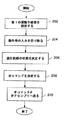
図2は、流体系102を制御する方法の一実施形態を示す。この方法は、第1運動不感帯を設定し、操作者の入力を受け取り、液圧回路の状態を決定し、弁コマンドを決定し、弁コマンドを弁アセンブリへ送るステップを含む。
【0021】
第1の制御ブロック202において、第1運動不感帯が設定または較正される。一実施形態において、流体系102の第1運動不感帯は、経験的に決定されても良い。例えば、エンジン速度が高アイドル(例えば、2,100rpm)に設定され、ポンプ容量が最大容量に維持されても良い。それゆえに、エンジン速度、ポンプ容量、および、流体流量のような液圧回路104の状態は、一定値に維持され得る。そして、アクチュエータ44、45は、移動するように指令される。一実施形態において、ジョイスティック28,30は、中立位置から、例えば、アクチュエータ44の伸長を指令する第1の位置まで移動される。ジョイスティックコマンドは、制御装置22へ送られる。制御装置22は、対応する弁コマンドを決定すると共に弁アセンブリ122へ送り、弁124,126が適切な位置に移動できるようにする。初期ジョイスティック位置と、最初のアクチュエータ運動が起こるジョイスティックの位置との間の範囲、例えば、3度が、較正または設定された第1運動不感帯と称され得る。
【0022】
図3は、ジョイスティックの入力および弁アセンブリ120,122へ送られる弁コマンドの関数として較正または設定された第1運動不感帯308をもたらすコマンド曲線302を示す。結果として得られるコマンド曲線302は、較正コマンド曲線と称されても良い。一実施形態において、較正コマンド曲線302は、所望の第1運動不感帯、例えば、3度、を決定することによって設定されても良い。そして、弁コマンドは、経験的解析を通じて、所定のエンジン速度およびポンプ容量でシリンダ44,45の最初の運動を生じさせるために、3度のジョイスティックの振れで、弁120,122が適切な位置に達することができるように、適切な流れを弁120,122へ送るべく較正されても良い。好適な実施形態において、アクチュエータの最初の運動は、適切な作業器具(図示せず)、または、アクチュエータ44の動きを見ることによって視覚的に検出されても良い。代わりに、アクチュエータの位置を検出するようにされた位置センサが、アクチュエータ44の運動および位置を検出するために使用されても良い。
【0023】
較正曲線302、関連するジョイスティック位置、および、弁コマンドは、メモリ内のテーブルに記憶されるとよく、較正コマンドテーブルと称され得る。較正コマンドテーブルは、適切な弁コマンドを決定すべく、ジョイスティックの入力が較正テーブルと比較されるように使用され得る。液圧回路104の状態が、較正テーブルが決定されたときと同じであるとき、第1運動不感帯も同じになる。
【0024】
第2の制御ブロック204において、機械102の作動中、操作者の入力は制御装置22によって受け取られる。好適な実施形態において、そのコマンドは、ジョイスティック28、30を操作する操作者に応答するように、ジョイスティック28、30から受け取られる。
【0025】
第3の制御ブロックにおいて、流体系102に配置された液圧回路104の状態が決定される。好適な実施形態において、その状態は、エンジン速度およびポンプ容量を含む。ポンプ容量は、ポンプを駆動するエンジン32の速度を決定することによって決定され得る。代替的な実施形態では、その状態は、流体流量、および/または、機械が実行する作業機能を含む。作業機能の例は、ブレード上昇、ブレード下降、ラック、ダンプ機能を含み、以下で詳述されよう。一実施形態において、液圧回路104の状態は、連続的に監視され、操作者の入力が受け取られたときに利用可能となるであろう。
【0026】
第4の制御ブロック208において、弁コマンドは、液圧回路の状態および操作者の入力に応じて決定される。コマンドは、結果として得られる第1運動不感帯が、設定された第1運動不感帯と一致するように決定される。つまり、例えば、エンジン速度、および/または、ポンプ容量が変化していたとしても、第1運動不感帯は、同じになるか、または、設定された第1運動不感帯の小さな閾値の範囲内にあることになる。
【0027】
本発明が用いられなければ、エンジン速度が変化すると、第1運動不感帯も変化する。例えば高アイドルにおけるポンプエンジンおよび最大容量におけるポンプで較正された較正コマンド曲線302を使用すると、減じられたエンジン速度について決定される第1運動不感帯310は、設定または較正された第1運動不感帯308よりも大きくなるであろう。本発明によって決定された弁コマンドは、決定された第1運動不感帯が、設定されている第1運動不感帯と一致するように決定される。
【0028】
一実施形態において、適切な弁コマンドは、操作者の入力、エンジン速度およびポンプ容量、ならびに、設定された第1運動不感帯または較正コマンド曲線302に基づいて決定される。較正コマンド曲線302のようなコマンド曲線は、各曲線が一定の第1運動不感帯308をもたらすように、ポンプエンジン速度およびポンプ容量の範囲に対して経験的に決定される。コマンド曲線は、高アイドル、中間アイドル、および低アイドルのエンジン速度、ならびに、最大および最小ポンプ容量に対してそれぞれ展開されても良い。例えば、最大ポンプ容量および低アイドルエンジン速度においても、コマンド曲線402は、図4に示されるように、一定の不感帯308をもたらすであろう。そして、これら較正曲線は、較正コマンド曲線302と比較される。弁コマンドオフセットは、各曲線の第1運動不感帯が、設定された第1運動不感帯308と一致するように、較正コマンド曲線302と決定されたコマンド曲線との差に基づいて、コマンド曲線毎に決定されても良い。弁コマンドオフセットテーブルは、エンジン速度およびポンプ容量を変動させる範囲に対して設定されるとともに記憶され得る。従って、流体系102の動作中、適切なコマンド曲線を決定するために、高アイドルおよび最大ポンプ容量で展開された較正コマンド曲線302は、較正されたコマンドを決定するためにアクセスされる。そして、較正されたコマンドオフセットは、実際のエンジン速度およびポンプ容量を決定すると共に、較正されたオフセットテーブルから適切なオフセットにアクセスすることによって決定される。較正されたオフセットは、較正されたコマンドに加算され、弁アセンブリ120,122へ送られた際に適切な弁位置をもたらすであろう弁コマンドを生じる。こうして、決定されたコマンド弁コマンドが、設定された第1運動不感帯、例えば、3度のジョイスティック不感帯をもたらすことになる。例えば、図5Aは、最大ポンプ容量に対するエンジン速度の関数としての弁コマンドオフセット曲線502を示す。図5Bは、最小ポンプ容量に対するエンジン速度の関数としての弁コマンドオフセット曲線504の一例を示す。一実施形態では、較正されたオフセットマップが、図6に示されるように、エンジン速度およびポンプ容量を変化させるために展開されても良い。較正オフセットマップ602は、ポンプ速度および容量を変化させるためのオフセットマップの一例である。
【0029】
代替的な実施形態では、各曲線が、設定された第1運動不感帯をもたらすように、補正コマンド曲線を、エンジン速度およびポンプ容量毎に経験的に設定してもよい。機械の作動中、エンジン速度およびポンプ容量に基づいて適切な曲線が選択され得ると共に、適切な弁コマンドが操作者の入力に応じて適切な較正曲線から選択される。
【0030】
更に他の実施形態では、弁コマンドが、較正された応答曲線302および操作者の入力に応じて動的に決定されてもよい。つまり、速度またはポンプ容量の変化に対する予め定められたコマンド曲線を使用する代わりに、弁コマンドは、較正された第1運動不感帯を有するコマンド曲線をもたらすように確立された計算式を利用して動的に決定される。例えば、シリンダに対して決定された流量に基づいて、ジョイスティックの入力または弁コマンドが修正されるように、弁コマンド乗数が決定されてもよく、乗数によって一定のジョイスティック位置で不感帯が起こるであろう。
【0031】
他の実施形態では、コマンド曲線および関連するオフセットが、流量の変化に基づいて設定され得る。つまり、特定のエンジン速度およびポンプ容量に対してコマンド曲線を有する代わりに、その曲線は、流体の流量および/または圧力に直接的に基づいていても良い。流量は、エンジン速度およびポンプ容量に基づいて計算されてもよく、または、流量を直接的に計測するために流量センサ(図示せず)が用いられてもよい。その結果、機械の作動中に、流量が決定され、適切なコマンド曲線またはオフセットテーブルが、流量に基づいて、適切な弁コマンドを決定するように選択される。
【0032】
第5の制御ブロック210において、弁コマンドが決定されると、そのコマンドは、弁アッセンブリ120,122に送られ、それにより、液圧回路104の動作を制御する。
【0033】
他の実施形態では、較正オフセットは、特定の作業機能、変化するエンジン速度、および、ポンプ容量に対して決定され得る。例えば、ホイールローダのような土工機械の作業機能は、ブレード上昇機能、ブレード下降機能、ラック機能、および、ダンプ機能を含むであろう。各作業機能は、異なる回路状態で作動し、異なるジョイスティックの入力を必要とする。例えば、ブレード上昇コマンドは、ジョイスティック28、30の後方位置を必要とするであろう下降ブレードコマンドとは逆に、ジョイスティックの前方位置を必要とするであろう。従って、操作者の入力が受け取られた際に、液圧回路104の状態であるエンジン速度、ポンプ容量、および、現在の作業機能が決定され得る。弁コマンドは、適切に較正されたコマンド曲線、および上述された較正オフセットに応じて決定され得る。作業機能を考慮することは、作業器具および関連するアクチュエータによって経験される予測負荷を考慮することにもなる。従って、一実施形態において、作業機能を考慮することは、結果として得られる第1運動不感帯の精度を増大化させるであろう。
【0034】
他の代替的な実施形態において、クローズドセンタ弁(図示せず)が、弁アセンブリ120,122に使用されても良い。オープンセンタ弁を使用する実施形態に対して、上述された曲線およびテーブルに類似している較正コマンド曲線およびオフセットテーブルは、一定の第1運動不感帯を操作者に提供するのと同様に設定され得ると共に使用され得る。
【0035】
(産業上の利用可能性)
本発明は、流体系102を制御する方法および装置を提供する。流体系102は、エンジン106によって駆動されるポンプ32を有する液圧回路104を含む。ポンプ32は、弁アセンブリ120,122を通してアクチュエータ44,45へ流体を送る。その方法は、操作者の入力を受け取り、液圧回路104の状態を決定し、一定の不感帯をもたらす弁コマンドを流体の状態および操作者の入力に応じて決定し、弁コマンドを弁アセンブリ122へ送るステップを含む。
【0036】
操作時に、操作者が、例えば、適切なジョイスティック28,30を制御することによって、作業器具を動かすように命令すると、そのコマンドは制御装置22によって受け取られる。制御装置22は、操作者の入力に応じて適切な弁コマンドを決定する。弁コマンドは、エンジン速度、ポンプ容量、および、機械の現在の作業機能のような液圧回路104の状態を決定することによって決定される。操作者の入力および現在の回路状態は、較正された弁コマンドを決定するために、較正されたコマンド曲線と共に使用される。また、好適な実施形態において、弁オフセットテーブルは、現在のジョイスティックの入力および回路状態に応じて較正オフセットを決定するために、アクセスされる。そして、較正されたオフセットは、較正された弁コマンドに加算され、その結果得られた弁コマンドは、弁アセンブリ120、122へ送られる。送られた弁コマンドは、設定された第1運動不感帯と一致した第1運動不感帯をもたらす。一貫した第1運動不感帯は、操作者に、効率のよい機械動作をもたらす一貫した装置制御インターフェイスを提供するであろう。
【0037】
本発明の他の形態、目的および利点は、図面、開示、および、添付した特許請求の範囲の検討から得られる。
【図面の簡単な説明】
【図1】 流体系の一実施形態の高レベル線図である。
【図2】 流体系を制御する一方法の説明図である。
【図3】 ジョイスティック入力の関数としてのコマンド曲線、および、弁コマンドのグラフである。
【図4】 異なるエンジン速度についてのジョイスティック入力の関数としてのコマンド曲線、および、弁コマンドのグラフである。
【図5A】 ポンプ容量およびエンジン速度の関数としての弁コマンドオフセットのグラフである。
【図5B】 ポンプ容量およびエンジン速度の関数としての弁コマンドオフセットのグラフである。
【図6】 ポンプ容量およびエンジン速度の関数としての弁コマンドオフセットのグラフである。[0001]
(Technical field)
The present invention relates generally to fluid systems, and more particularly to a method and apparatus for controlling the dead zone of a fluid system.
[0002]
(Background technology)
A fluid control system mounted on an earthwork machine includes an operator interface that enables an operator to control the fluid system, and a hydraulic circuit that controls a work implement of the machine in response to an input from the operator. . The operator interface may include a joystick adapted to receive an operator input and generate an appropriate input signal for controlling the fluid system. The controller receives the input signal and determines an appropriate valve command. The valve command is sent to a valve assembly or a control valve that controls the flow of fluid from the pump to the actuator. In one embodiment, the valve assembly includes a pilot valve and a main valve. The earthwork machine instrument is connected to one or more actuators. Furthermore, the pump is driven by a pump engine.
[0003]
The controller determines valve commands in response to operator input signals and associated hydraulic circuit signals such as signals received from engine speed sensors. The valve command signal is sent to the appropriate valve assembly. In one embodiment, the valve command signal is sent to a pilot valve solenoid located within the valve assembly. The solenoid is then energized to control the valve spool in the pilot valve to achieve the proper position in response to the valve command signal. The pilot valve responsively sends pilot pressure to the main valve to move the main valve, i.e., the spool within the main valve, to a desired position. The main valve then allows fluid to be sent to the actuator.
[0004]
In the fluid control system, there is a dead zone associated with the movement of the joystick from the neutral position to the position where the initial movement of the controlled actuator occurs. This dead zone may be referred to as a first motion dead zone. The dead zone may be related in part to the variation in valve position required to provide the actuator with the proper amount of fluid flow to operate the actuator.
[0005]
Actuator responsiveness depends in part on fluid pressure and fluid flow rate to the actuator. Fluid pressure and fluid flow, in turn, depend in part on main valve position, engine speed, and pump capacity.
[0006]
The first motion dead zone is due in part to the amount that the main valve must move before the main valve can flow the appropriate fluid to the actuator. This dead band between the initial position of the joystick and the position of the joystick where the initial movement of the actuator occurs corresponds to a given engine speed, pump capacity and load. However, when the pump engine speed is reduced, for example from a high idle speed to a low idle speed, the same joystick command as at high idle speed will not result in the same actuator response at low idle speed. Thus, the joystick command must be increased, for example, to provide sufficient fluid flow to the actuator to achieve the same actuator response as in high idle conditions when engine speed is reduced. Will.
[0007]
As a result, the first motion dead zone varies partially depending on the engine speed and the pump capacity of the hydraulic circuit. Variations in the first motion dead zone will result in an inconsistent operator interface that reduces operator efficiency and may result in machine malfunction.
[0008]
The present invention is directed to overcoming one or more of the problems set forth above.
[0009]
(Disclosure of the Invention)
In one aspect of the present invention, a method for controlling a fluid system is disclosed. The fluid system includes a hydraulic circuit having a pump driven by the engine. The pump delivers fluid through the valve assembly to the actuator. The method includes receiving an operator input, determining a state of the hydraulic circuit, determining a valve command in response to the circuit state and the operator input, and sending the valve command to the valve assembly.
[0010]
In another aspect of the invention, a method for controlling a fluid system is disclosed. The fluid system includes a hydraulic circuit having a pump driven by the engine. The pump delivers fluid through the valve assembly to the actuator. The method includes the steps of setting a first motion dead zone, receiving an operator input, determining an engine speed, and determining a valve command in response to the engine speed and the operator input.
[0011]
In another form of the invention, an apparatus adapted to control a fluid system is disclosed. The fluid system includes a hydraulic circuit having a pump driven by the engine. The pump delivers fluid through the valve assembly to the actuator. An apparatus includes an input control device adapted to receive an operator input and responsively generate an input signal; and an engine adapted to detect an engine speed and responsively generate an engine speed signal. A speed sensor and a controller that receives the input signal and the speed signal, determines a valve command in response to the input signal and the speed signal, and sends the valve command to the valve assembly.
[0012]
(Best Mode for Carrying Out the Invention)
The present invention provides an apparatus and method for controlling a fluid system. FIG. 1 is an explanatory diagram of an embodiment of a
[0013]
The
[0014]
Each of the first and
[0015]
The
[0016]
The
[0017]
The
[0018]
Although FIG. 1 illustrates one embodiment of the
[0019]
One of the objects of the present invention is to maintain a constant first motion dead zone to provide a consistent control interface to the machine operator regardless of fluid flow rate, engine speed, or pump capacity. It is in. The initial movement of the
[0020]
FIG. 2 illustrates one embodiment of a method for controlling the
[0021]
In a
[0022]
FIG. 3 shows a
[0023]
The
[0024]
In a
[0025]
In the third control block, the state of the
[0026]
In the
[0027]
If the present invention is not used, the first motion dead zone changes as the engine speed changes. For example, using a
[0028]
In one embodiment, the appropriate valve command is determined based on operator input, engine speed and pump capacity, and the set first motion deadband or
[0029]
In an alternative embodiment, the correction command curve may be set empirically for each engine speed and pump capacity so that each curve provides a set first motion dead zone. During machine operation, an appropriate curve can be selected based on engine speed and pump displacement, and an appropriate valve command can be selected from an appropriate calibration curve in response to operator input.
[0030]
In yet other embodiments, the valve command may be dynamically determined in response to the calibrated
[0031]
In other embodiments, the command curve and associated offset may be set based on changes in flow rate. That is, instead of having a command curve for a particular engine speed and pump capacity, the curve may be based directly on fluid flow and / or pressure. The flow rate may be calculated based on engine speed and pump capacity, or a flow sensor (not shown) may be used to directly measure the flow rate. As a result, during operation of the machine, the flow rate is determined and an appropriate command curve or offset table is selected to determine an appropriate valve command based on the flow rate.
[0032]
In the
[0033]
In other embodiments, the calibration offset may be determined for a particular work function, changing engine speed, and pump capacity. For example, the work functions of an earthwork machine such as a wheel loader may include a blade raising function, a blade lowering function, a rack function, and a dump function. Each work function operates in a different circuit state and requires a different joystick input. For example, a blade up command would require a joystick forward position as opposed to a lower blade command that would require a rear position of the
[0034]
In other alternative embodiments, closed center valves (not shown) may be used for valve assemblies 120,122. For embodiments using an open center valve, a calibration command curve and offset table similar to the curve and table described above can be set up to provide a constant first motion dead zone to the operator. Can be used together.
[0035]
(Industrial applicability)
The present invention provides a method and apparatus for controlling the
[0036]
In operation, if the operator instructs to move the work implement, for example by controlling the
[0037]
Other aspects, objects, and advantages of the invention can be obtained from a study of the drawings, the disclosure, and the appended claims.
[Brief description of the drawings]
FIG. 1 is a high level diagram of one embodiment of a fluid system.
FIG. 2 is an explanatory diagram of a method for controlling a fluid system.
FIG. 3 is a graph of command curves and valve commands as a function of joystick input.
FIG. 4 is a graph of command curves and valve commands as a function of joystick input for different engine speeds.
FIG. 5A is a graph of valve command offset as a function of pump capacity and engine speed.
FIG. 5B is a graph of valve command offset as a function of pump capacity and engine speed.
FIG. 6 is a graph of valve command offset as a function of pump capacity and engine speed.
Claims (8)
操作者によるジョイスティックの入力を受け取るステップと、
エンジン速度及びポンプ容量の双方を含む前記液圧回路の状態を決定するステップと、
前記ジョイスティックの初期位置から前記アクチュエータの初期運動が起こる前記ジョイスティックの位置までの前記ジョイスティックの移動量である第1運動不感帯を一定にするための弁コマンドを前記液圧回路の状態および前記ジョイスティックの入力に応じて検出するステップと、
前記弁コマンドを弁アセンブリへ送るステップと、
を備えることを特徴とする方法。A method of controlling a fluid system including a hydraulic circuit having a pump driven by an engine, the pump delivering fluid through a valve assembly to an actuator comprising:
Receiving a joystick input by an operator;
Determining the state of the hydraulic circuit including both engine speed and pump capacity;
A valve command for making a first motion dead band, which is the amount of movement of the joystick from the initial position of the joystick to the position of the joystick where the initial movement of the actuator occurs, is input to the state of the hydraulic circuit and the input of the joystick Detecting according to
Sending the valve command to a valve assembly;
A method comprising the steps of:
マンドは、前記ジョイスティックの入力、前記液圧回路の状態、および、前記作業機能に応じて決定されることを特徴とする請求項1に記載の方法。Determining the working function of the hydraulic circuit (104), wherein the valve command is determined according to the input of the joystick, the state of the hydraulic circuit, and the working function. The method of claim 1.
操作者によるジョイスティックの入力を受け取るステップと、
前記ジョイスティックの初期位置から前記アクチュエータの初期運動が起こる前記ジョイスティックの位置までの前記ジョイスティックの移動量である第1運動不感帯(308)の目標値を設定するステップと、
エンジン速度およびポンプ容量を検出するステップと、
前記第1運動不感帯(308)が前記目標値に一致するように、前記エンジン速度および前記ポンプ容量と前記操作者によるジョイスティックの入力に応じて弁コマンドを決定するステップと、
を有することを特徴とする方法。A fluid system (102) including a hydraulic circuit (104) having a pump (32) driven by an engine (106), wherein the pump (32) passes fluid through a valve assembly (120, 122) to an actuator (44, 45). ) Control,
Receiving a joystick input by an operator;
Setting a target value of a first motion dead zone (308), which is the amount of movement of the joystick from the initial position of the joystick to the position of the joystick where the initial motion of the actuator occurs;
Detecting engine speed and pump capacity;
Determining a valve command in accordance with the engine speed and the pump displacement and a joystick input by the operator so that the first motion dead zone (308) matches the target value;
A method characterized by comprising:
操作者によるジョイスティックの入力を受け取り、応答的に入力信号を発生するようにされた入力制御装置と、
エンジンの速度を検出し、応答的にエンジン速度信号を発生するようにされたエンジン速度センサと、
ポンプ容量を検出する手段と、
前記ジョイスティックの初期位置から前記アクチュエータの初期運動が起こる前記ジョイスティックの位置までの前記ジョイスティックの移動量である第1運動不感帯を一定にするための弁コマンドを、前記入力信号と、前記エンジン速度信号およびポンプ容量に応じて決定し、前記弁コマンドを弁アセンブリへ送るように構成された制御装置と、
を具備することを特徴とする装置。A device comprising a hydraulic circuit having a pump driven by an engine, wherein the pump is adapted to control a fluid system that delivers fluid through a valve assembly to an actuator,
An input control device configured to receive an input of a joystick by an operator and generate an input signal in response;
An engine speed sensor adapted to detect engine speed and responsively generate an engine speed signal;
Means for detecting the pump capacity;
A valve command for making a first motion dead band, which is a movement amount of the joystick from an initial position of the joystick to a position of the joystick where the initial motion of the actuator occurs, a valve command for the input signal, the engine speed signal, and A controller configured to determine the pump capacity and send the valve command to the valve assembly;
The apparatus characterized by comprising.
Applications Claiming Priority (3)
| Application Number | Priority Date | Filing Date | Title |
|---|---|---|---|
| US09/282,339 | 1999-03-31 | ||
| US09/282,339 US6305162B1 (en) | 1999-03-31 | 1999-03-31 | Method and apparatus for controlling the deadband of a fluid system |
| PCT/US2000/007950 WO2000058633A1 (en) | 1999-03-31 | 2000-03-24 | Method and apparatus for controlling the deadband of a fluid system |
Publications (3)
| Publication Number | Publication Date |
|---|---|
| JP2002540366A JP2002540366A (en) | 2002-11-26 |
| JP2002540366A5 JP2002540366A5 (en) | 2007-05-10 |
| JP4746750B2 true JP4746750B2 (en) | 2011-08-10 |
Family
ID=23081060
Family Applications (1)
| Application Number | Title | Priority Date | Filing Date |
|---|---|---|---|
| JP2000608097A Expired - Fee Related JP4746750B2 (en) | 1999-03-31 | 2000-03-24 | Method and apparatus for controlling dead zone of fluid system |
Country Status (5)
| Country | Link |
|---|---|
| US (1) | US6305162B1 (en) |
| JP (1) | JP4746750B2 (en) |
| AU (1) | AU4029300A (en) |
| DE (1) | DE10084435T1 (en) |
| WO (1) | WO2000058633A1 (en) |
Families Citing this family (26)
| Publication number | Priority date | Publication date | Assignee | Title |
|---|---|---|---|---|
| US20030112219A1 (en) * | 2001-12-14 | 2003-06-19 | Imed Gharsalli | Input/output interface control |
| US7007466B2 (en) * | 2001-12-21 | 2006-03-07 | Caterpillar Inc. | System and method for controlling hydraulic flow |
| US6651544B2 (en) | 2001-12-28 | 2003-11-25 | Caterpillar Inc | Controlling the deadband of a fluid system |
| US7096967B2 (en) * | 2002-07-15 | 2006-08-29 | Steiner Turf Equipment, Inc. | Robotic sod stacker with software control |
| JP2005523040A (en) * | 2002-07-15 | 2005-08-04 | スタイナー・ターフ・イクイップメント・インコーポレイテッド | Winding conveyor for turf harvester |
| US7066277B2 (en) * | 2002-07-15 | 2006-06-27 | Steiner Turf Equipment, Inc. | Robotic sod stacker |
| US7070004B2 (en) | 2002-07-15 | 2006-07-04 | Steiner Turf Equipment, Inc. | Robotic sod stacker |
| US6990807B2 (en) * | 2002-12-09 | 2006-01-31 | Coneqtec Corporation | Auxiliary hydraulic drive system |
| DE102004057878B4 (en) * | 2003-12-08 | 2014-01-23 | Continental Teves Ag & Co. Ohg | Method for calibrating analog controlled hydraulic valves |
| KR100621981B1 (en) * | 2004-04-08 | 2006-09-14 | 볼보 컨스트럭션 이키프먼트 홀딩 스웨덴 에이비 | discharge compensation method of neutral condition of heavy equipment joystick |
| US7139621B2 (en) * | 2004-12-16 | 2006-11-21 | Caterpillar Inc | Floating deadband control |
| WO2007112502A1 (en) * | 2006-04-03 | 2007-10-11 | Murray Andrew Hodges | Valve closure allowing for some deadband travel |
| US7624836B2 (en) * | 2006-10-30 | 2009-12-01 | Caterpillar Inc. | Steering system having multiple strategies and variable deadzone |
| US7665971B1 (en) * | 2008-01-15 | 2010-02-23 | Mi-Jack Products, Inc. | Method of obtaining required power on demand from an engine |
| KR20110127343A (en) * | 2010-05-19 | 2011-11-25 | 두산산업차량 주식회사 | Lift speed control system of a working device for a heavy equipment |
| US9453503B2 (en) * | 2012-01-09 | 2016-09-27 | Eaton Corporation | Method for obtaining a full range of lift speeds using a single input |
| KR102445784B1 (en) | 2014-05-06 | 2022-09-21 | 단포스 파워 솔루션스 Ii 테크놀로지 에이/에스 | Hydraulic hybrid propel circuit with hydrostatic option and method of operation |
| EP3212446B1 (en) | 2014-10-27 | 2022-05-11 | Danfoss Power Solutions II Technology A/S | Hydraulic hybrid propel circuit with hydrostatic option and method of powering an accessory function of a hydraulic system for a mobile work vehicle |
| SE539241C2 (en) | 2015-10-19 | 2017-05-23 | Husqvarna Ab | Adaptive control of hydraulic tool on remote demolition robot |
| SE542526C2 (en) | 2015-10-19 | 2020-06-02 | Husqvarna Ab | Energy buffer arrangement and method for remote controlled demolition robot |
| SE542525C2 (en) | 2015-10-19 | 2020-06-02 | Husqvarna Ab | Automatic tuning of valve for remote controlled demolition robot |
| US10167951B2 (en) | 2016-02-11 | 2019-01-01 | Deere & Company | System and method for calibrating a hydraulic drive system |
| CN106320421A (en) * | 2016-08-31 | 2017-01-11 | 徐州徐工挖掘机械有限公司 | Rotary energy recycling system for excavator |
| WO2020102408A1 (en) * | 2018-11-13 | 2020-05-22 | Husco International, Inc. | Hydraulic control systems and methods using multi-function dynamic control |
| EP3657028B1 (en) * | 2018-11-21 | 2023-08-16 | Danfoss Power Solutions Aps | Method for controlling a hydraulic actuator |
| US11009048B1 (en) * | 2020-09-09 | 2021-05-18 | Robert Bosch Gmbh | Boom lift system |
Citations (2)
| Publication number | Priority date | Publication date | Assignee | Title |
|---|---|---|---|---|
| JPH05215105A (en) * | 1992-02-06 | 1993-08-24 | Toyota Autom Loom Works Ltd | Hydraulic control device for cargo handling in industrial vehicle |
| JPH06146344A (en) * | 1992-11-05 | 1994-05-27 | Yutani Heavy Ind Ltd | Device for operating construction machine |
Family Cites Families (8)
| Publication number | Priority date | Publication date | Assignee | Title |
|---|---|---|---|---|
| US3821625A (en) | 1972-09-18 | 1974-06-28 | Caterpillar Tractor Co | Control circuit with deadband compensation for electrically actuated devices |
| NL8501581A (en) | 1985-06-03 | 1987-01-02 | Nedap Nv | METHOD FOR SELECTIVE FILLING OR EMPTYING STORAGE OR STOCK TANKS. |
| JPS6455446U (en) | 1987-10-02 | 1989-04-05 | ||
| US5630317A (en) | 1993-03-26 | 1997-05-20 | Kabushiki Kaisha Komatsu Seisakusho | Controller for hydraulic drive machine |
| US5737993A (en) | 1996-06-24 | 1998-04-14 | Caterpillar Inc. | Method and apparatus for controlling an implement of a work machine |
| US5848609A (en) | 1996-11-26 | 1998-12-15 | Worcester Control Licenseco Inc. | Digital valve positioner |
| US5784945A (en) * | 1997-05-14 | 1998-07-28 | Caterpillar Inc. | Method and apparatus for determining a valve transform |
| DE19839062C2 (en) | 1997-08-29 | 2002-04-18 | Komatsu Mfg Co Ltd | Hydraulic machine control |
-
1999
- 1999-03-31 US US09/282,339 patent/US6305162B1/en not_active Expired - Lifetime
-
2000
- 2000-03-24 DE DE10084435T patent/DE10084435T1/en not_active Withdrawn
- 2000-03-24 WO PCT/US2000/007950 patent/WO2000058633A1/en active Application Filing
- 2000-03-24 AU AU40293/00A patent/AU4029300A/en not_active Abandoned
- 2000-03-24 JP JP2000608097A patent/JP4746750B2/en not_active Expired - Fee Related
Patent Citations (2)
| Publication number | Priority date | Publication date | Assignee | Title |
|---|---|---|---|---|
| JPH05215105A (en) * | 1992-02-06 | 1993-08-24 | Toyota Autom Loom Works Ltd | Hydraulic control device for cargo handling in industrial vehicle |
| JPH06146344A (en) * | 1992-11-05 | 1994-05-27 | Yutani Heavy Ind Ltd | Device for operating construction machine |
Also Published As
| Publication number | Publication date |
|---|---|
| JP2002540366A (en) | 2002-11-26 |
| US6305162B1 (en) | 2001-10-23 |
| DE10084435T1 (en) | 2002-05-02 |
| AU4029300A (en) | 2000-10-16 |
| WO2000058633A1 (en) | 2000-10-05 |
Similar Documents
| Publication | Publication Date | Title |
|---|---|---|
| JP4746750B2 (en) | Method and apparatus for controlling dead zone of fluid system | |
| JP3510114B2 (en) | Work machine control method and its control device | |
| US5307631A (en) | Hydraulic control apparatus for hydraulic construction machine | |
| KR0175959B1 (en) | Hydraulic device for a working machine | |
| US8522543B2 (en) | Hydraulic control system utilizing feed-forward control | |
| KR950007624B1 (en) | Control system of hydraulic pump | |
| JP2657548B2 (en) | Hydraulic drive device and control method thereof | |
| US20080154466A1 (en) | System and method for controlling a machine | |
| JP6850707B2 (en) | Work machine | |
| US6560962B2 (en) | Control system of a hydraulic construction machine | |
| US6651544B2 (en) | Controlling the deadband of a fluid system | |
| JP2651079B2 (en) | Hydraulic construction machinery | |
| EP0491944B1 (en) | Speed change controller of running hydraulic motor | |
| JP2007298130A (en) | Hydraulic system of construction machine | |
| JPH07127493A (en) | Number of revolutions of prime mover control device for hydraulic construction machine | |
| JP3081988B2 (en) | Control device for hydraulic drive machine | |
| JP3137318B2 (en) | Control device for hydraulic drive machine | |
| JP6619939B2 (en) | Hydraulic drive system | |
| JPH04131510A (en) | Controller for hydraulic drive machine | |
| JP3175992B2 (en) | Control device for hydraulic drive machine | |
| JP3626537B2 (en) | Hydraulic actuator control device | |
| JP3137317B2 (en) | Control device for hydraulic drive machine | |
| JP3721696B2 (en) | Hydraulic control equipment for industrial vehicles | |
| JP3169166B2 (en) | Control device for hydraulic drive machine | |
| JP3330340B2 (en) | Control device for hydraulic drive machine |
Legal Events
| Date | Code | Title | Description |
|---|---|---|---|
| A521 | Written amendment |
Free format text: JAPANESE INTERMEDIATE CODE: A523 Effective date: 20070302 |
|
| A621 | Written request for application examination |
Free format text: JAPANESE INTERMEDIATE CODE: A621 Effective date: 20070302 |
|
| RD04 | Notification of resignation of power of attorney |
Free format text: JAPANESE INTERMEDIATE CODE: A7424 Effective date: 20070302 |
|
| A977 | Report on retrieval |
Free format text: JAPANESE INTERMEDIATE CODE: A971007 Effective date: 20091120 |
|
| A131 | Notification of reasons for refusal |
Free format text: JAPANESE INTERMEDIATE CODE: A131 Effective date: 20100223 |
|
| A601 | Written request for extension of time |
Free format text: JAPANESE INTERMEDIATE CODE: A601 Effective date: 20100524 |
|
| A602 | Written permission of extension of time |
Free format text: JAPANESE INTERMEDIATE CODE: A602 Effective date: 20100531 |
|
| A521 | Written amendment |
Free format text: JAPANESE INTERMEDIATE CODE: A523 Effective date: 20100618 |
|
| A131 | Notification of reasons for refusal |
Free format text: JAPANESE INTERMEDIATE CODE: A131 Effective date: 20101228 |
|
| A521 | Written amendment |
Free format text: JAPANESE INTERMEDIATE CODE: A523 Effective date: 20110314 |
|
| TRDD | Decision of grant or rejection written | ||
| A01 | Written decision to grant a patent or to grant a registration (utility model) |
Free format text: JAPANESE INTERMEDIATE CODE: A01 Effective date: 20110428 |
|
| A01 | Written decision to grant a patent or to grant a registration (utility model) |
Free format text: JAPANESE INTERMEDIATE CODE: A01 |
|
| A61 | First payment of annual fees (during grant procedure) |
Free format text: JAPANESE INTERMEDIATE CODE: A61 Effective date: 20110516 |
|
| FPAY | Renewal fee payment (event date is renewal date of database) |
Free format text: PAYMENT UNTIL: 20140520 Year of fee payment: 3 |
|
| R150 | Certificate of patent or registration of utility model |
Free format text: JAPANESE INTERMEDIATE CODE: R150 |
|
| R250 | Receipt of annual fees |
Free format text: JAPANESE INTERMEDIATE CODE: R250 |
|
| R250 | Receipt of annual fees |
Free format text: JAPANESE INTERMEDIATE CODE: R250 |
|
| LAPS | Cancellation because of no payment of annual fees |