JP4746662B2 - Tractor - Google Patents
Tractor Download PDFInfo
- Publication number
- JP4746662B2 JP4746662B2 JP2008283103A JP2008283103A JP4746662B2 JP 4746662 B2 JP4746662 B2 JP 4746662B2 JP 2008283103 A JP2008283103 A JP 2008283103A JP 2008283103 A JP2008283103 A JP 2008283103A JP 4746662 B2 JP4746662 B2 JP 4746662B2
- Authority
- JP
- Japan
- Prior art keywords
- battery
- support portion
- frame structure
- engine room
- battery support
- Prior art date
- Legal status (The legal status is an assumption and is not a legal conclusion. Google has not performed a legal analysis and makes no representation as to the accuracy of the status listed.)
- Expired - Fee Related
Links
Images


Description
本発明は、エンジンルームを機体の前部に配備したトラクタに関する。 The present invention relates to a tractor in which an engine room is arranged at a front portion of an airframe.
[I]
(構成)
本発明の第1特徴は、トラクタにおいて次のように構成することにある。
機体の前部に配備されたエンジンルームの後部に原動部の後壁となるフレーム構造体を機体フレームから立設して、前記エンジンルームとその後方側の運転部側空間とを前記後壁となるフレーム構造体で隔てるとともに、前記フレーム構造体の上部にステアリングハンドルを備え、
前記フレーム構造体を、側面視で上下方向に沿った前後に扁平な形状に形成された隔壁部と、その隔壁部の後方側で後向きに突設形成されたバッテリ支持部とを備えて構成し、
前記隔壁部を、前記エンジンルームを覆うエンジンボンネットの後端部の左右幅に合わせた横幅に形成して、その隔壁部の外周に沿って前記エンジンボンネットの後端が配備されるように構成し、
前記バッテリ支持部を、バッテリを支持する下壁部と、バッテリの左右横側に位置する左右の横壁部と、バッテリの上側に位置する上壁部とを備えて、その内部空間が前後に貫通するように形成し、このバッテリ支持部の内部空間にバッテリを入り込ませて配置する。
[I]
(Constitution)
The first feature of the present invention is that the tractor is configured as follows.
A frame structure that serves as a rear wall of the prime mover is erected from the fuselage frame at the rear of the engine room disposed in the front of the machine body, and the engine room and the driving unit side space behind the engine room are arranged with the rear wall. with separating a frame structure comprising, Bei example the steering wheel to the top of the frame structure,
The frame structure includes a partition wall formed in a flat shape in the front-rear direction along the vertical direction in a side view, and a battery support portion formed to project rearward on the rear side of the partition wall. ,
The partition portion is formed to have a lateral width that matches a lateral width of a rear end portion of the engine bonnet that covers the engine room, and the rear end of the engine bonnet is arranged along the outer periphery of the partition portion. ,
The battery support portion includes a lower wall portion that supports the battery, left and right lateral wall portions that are located on the left and right sides of the battery, and an upper wall portion that is located on the upper side of the battery, and the internal space penetrates forward and backward. The battery is inserted into the internal space of the battery support portion and arranged.
[II]
(構成)
本発明の第2特徴は、本発明の第1特徴のトラクタにおいて次のように構成することにある。
前記隔壁部の中央部に、前記バッテリ支持部によって形成される前後に貫通する開口よりも左右方向に大きな開口を形成する。
[II]
(Constitution)
The second feature of the present invention is that the tractor according to the first feature of the present invention is configured as follows.
An opening larger in the left-right direction than the opening penetrating in the front-rear direction formed by the battery support portion is formed in the central portion of the partition wall portion .
[III]
(構成)
本発明の第3特徴は、本発明の第1又は第2特徴のトラクタにおいて次のように構成することにある。
前記バッテリ支持部の下壁部の後端をステーで前記機体フレームに支持する。
[III]
(Constitution)
The third feature of the present invention is that the tractor according to the first or second feature of the present invention is configured as follows.
A rear end of the lower wall portion of the battery support portion is supported on the body frame by a stay .
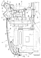
図1に、本発明に係る原動部構造を備えたトラクタが示されている。このトラクタは、前輪1および後輪2が駆動される四輪駆動仕様に構成されており、エンジン3をエンジンボンネット4で囲繞した原動部5が機体前部に備えられるとともに、左右後輪2の間に位置させて運転座席6が配備され、かつ、運転座席6の後部には門形の転倒保護フレーム7が立設されている。
FIG. 1 shows a tractor having a driving part structure according to the present invention. This tractor is configured to have a four-wheel drive specification in which the front wheels 1 and the
前記エンジンボンネット4は、固定された下部ボンネット4aと、前部の支点p周りに上下に揺動開閉可能な上部ボンネット4bとで構成されており、このエンジンボンネット4で形成されたエンジンルームRの内部に、ラジエータ8を後置きにして前記エンジン3およびこれに付随する各種機器が収容配置されている。
The
エンジンルームRの後部には、原動部5の後壁となるフレーム構造体10が立設され、このフレーム構造体10にパネルカバー11とその下方に連なるセンターカバー12が装着されている。
At the rear part of the engine room R, a
パネルカバー11には計器パネル13や各種スイッチ類が装着されるとともに、センターカバー12には防塵構造の通気口14が形成され、この通気口14から導入された外気がラジエータファン9によって吸引されてラジエータ8に導かれた後、エンジンルームR内を前方に流動し、ルーム内の熱気がエンジンボンネット4の前面および左右前部の通気口15から機外に排出されるようになっている。
The
エンジンボンネット4の下部を構成する前記下部ボンネット4aは平面形状が後向きに開放されたコの字形に形成されて機体フレーム16に連結固定されており、この下部ボンネット4aの前面および左右側面の前部に網目構造の前記通気口15が形成されている。
The
前記上部ボンネット4bは、機体フレーム16から立設された固定支持枠17の上端部に前記支点p周りに揺動可能に枢支連結されており、その前端部に左右一対の前照灯18が取り付けられている。上部ボンネット4bにおける前端部内面に取付けられた支点金具19の左右中央部位と前記固定支持枠17の左右中央部位から延出されたステー17aとに亘ってガススプリング20が架設され、図3に示すように、ガススプリング20の伸長付勢力によって上部ボンネット4bがメンテナンス作業が可能な開放位置で安定保持されるように、ガススプリング20の伸長付勢特性が上部ボンネット4bの重量に対応して設定されている。
The
また、上部ボンネット4bは、その遊端側に配備された係止ロック機構21によって閉じ姿勢に保持されるようになっている。つまり、図3に示すように、上部ボンネット4bにおける後方遊端部の中央部位には係止ピン22が支持金具23を介して固設されるとともに、フレーム構造体10の上端部には、前記係止ピン22に係合されるフック状のロック金具24が支点a周りに横回動可能に枢着されている。このロック金具24はバネ25によって係合ロック方向に回動付勢されており、図11(イ)に示すように、ガススプリング20に抗して閉じられた上部ボンネット4bの係止ピン22にロック金具24が係合されることで、上部ボンネット4bが閉じ位置に保持されるようになっている。
The
前記ロック金具24には操作レバー24aが連設されてパネルカバー11の上方に突出されており、図11(ロ)に示すように、操作レバー24aを横方向に揺動操作してロック金具24をバネ25に抗して回動させることで、ロック解除された上部ボンネット4bがガススプリング20の付勢力によって少し持上げられることになり、ここに手指をかけて上部ボンネット4bを大きく揺動開放するだけでガススプリング20によってその開放位置に保持される。
An
なお、図3〜図5に示すように、ガススプリング20が連結された支点金具19と係止ピン22の支持金具23とに亘る前後に長いステー26が上部ボンネット4bの天板部内面に沿って縦向き姿勢で設けられて、樹脂成形された上部ボンネット4bが補強されている。これによって、後端を係止固定された状態で上部ボンネット4bがガススプリング20の上方付勢力を受けて撓むことが抑止されている。
As shown in FIGS. 3 to 5,
原動部5の後壁となる前記フレーム構造体10は、図8に示すように、アルミダイカスト成形された左右に幅広で前後に扁平な隔壁部10Aと、同じくアルミダイカスト成形された左右分割構造の支持枠部10Bとを連結して構成されており、両者10A,10Bが適所で前後方向に位置決め嵌合されて6本のボルト27で連結されている。
As shown in FIG. 8, the
図6に示すように、フレーム構造体10を構成する前記隔壁部10Aは、原動部5の後端部における左右幅に合わせた横幅に形成され、隔壁部10Aの外周に沿って前記エンジンボンネット4の後端、および、センターカバー12の前端が配備されるようになっている。また、隔壁部10Aの中央部に形成された大きい開口28にラジエータ8の吸気部が臨設されており、前記センターカバーの通気口14から取り入れられた外気がフレーム構造体10を通してラジエータ8に導かれるようになっている。また、この隔壁部10Aの左右下端部から横外方に向けてステップ支持部10cが突設され、運転座席6の足元に配備されるステップ29の前部左右がこのステップ支持部10cに載置固定されている。また、隔壁部10Aの左右外周部には下方に向けて鉤形に屈曲された凹部30が形成されており、ここに配線や油圧ホースHが側方から挿通されて凹部30の底側で安定保持されるようになっている。
As shown in FIG. 6, the
図10に示すように、フレーム構造体10を構成する左右分割構造の前記支持枠部10Bは互いにボルト連結され、その下端部には左右一対の脚部10dが備えられている。各脚部10dは後方に向けて大きく延出されており、この脚部10dを機体フレーム16の上に載置してボルト連結することでフレーム構造体10全体を安定良く立設固定することができるようになっている。
As shown in FIG. 10, the
また、支持枠部10Bの上半部には前後に貫通開口された箱形部10eが設けられてバッテリ支持部Bが形成されている。このバッテリ支持部Bは前記脚部10dから所定距離上方に離れて後向きに突設形成されており、箱形に形成されたバッテリ支持部Bの内部空間にバッテリ31を後方から差し入れて取付け固定することができるようになっている。なお、この箱形部10eの後端と機体フレーム16とをステー32で連結して、バッテリ重量を受けるバッテリ支持部Bの補強がなされている。また、箱形部10eの左右の横壁部には開口33が形成されて、バッテリ収容空間の通風を良くするとともにバッテリ支持部Bの軽量化が図られている。
Further, a box-
箱形に形成された前記バッテリ支持部Bの上壁部には、後方上方に向けて取付け座10fが延出され、ここにパワーステアリング用の油圧コントローラ34が連結されることで、左右分割構造の支持枠部10Bが上部でも連結されるようになっている。油圧コントローラ34からは上方に向けて操作軸35が延出されてステアリングハンドル36が装着されている。前記油圧コントローラ34は、ステアリングハンドル36の回転操作量に応じた量の圧油をハンドル操作方向に対応した方向に送り出して前輪操向用の油圧シリンダ37に油圧ホースHを介して供給するよう構成されている。
A mounting
前記脚部10dはバルブ支持部Vとしての機能を備えており、図14に示すように、左右脚部10dの上面に亘って支持板38を取付け、この支持板38の上にバルブ39を取付けることができるようになっている。
The
前記バルブ39は、油圧駆動型の付設作業装置を駆動するためのものであり、図12〜図14に、機体前部に付設作業装置の一例であるフロントローダ40を連結した仕様のトラクタ、および、その操縦部が示されている。
The
前記フロントローダ40は、トラクタ本機1の前部左右に備えられた支持ブラケット41に脱着自在に連結固定される左右一対の支持フレーム42、各支持フレーム42の上端部に上下揺動可能に連結された左右一対のブーム43、および、左右のブーム43の前端に亘って上下回動可能に連結されたバケット44とで構成されており、リフトシリンダ45によってブーム43が駆動昇降されるとともに、チルトシリンダ46によってバケット44が駆動回動されるようになっている。
The
また、フレーム構造体10の上部右横側に、前記バルブ39を操作する操作レバー47が配備されており、バルブ39と操作レバー47との連係構造を以下に説明する。
Further, an
前記バルブ39には左右スライド可能に2本のスプール48,49が装備されて機体右方に突設されており、一方のスプール48を3位置に切換えスライドすることでリフトシリンダ45の伸縮および中立固定状態を選択し、他方のスプール49を3位置に切換えスライドすることでチルトシリンダ46の伸縮および中立固定状態を選択するようになっている。
The
前記操作レバー47と2本の前記スプール48,49はリンク機構50を介して連動連結されており、その詳細な構造が図14,図15に示されている。
The
前記フレーム構造体10の上部右側箇所に支持ブラケット51がボルト連結され、この支持ブラケット51に備えられた横向きボス部52にレバー支軸53が横向き軸心x周りに回動自在に挿通支持されている。そして、レバー支軸53の外端部に前記横向き軸心xと直交する前後向き軸心y周りに左右回動自在にピン連結された回動金具54に前記操作レバー47が連結され、もって、操作レバー47が直交する2つの軸心x,y周りに十字揺動操作可能に支持されている。
A
レバー支軸53の内方端部には操作アーム55が一体連設されており、この操作アーム55とリフトシリンダ用のスプール48の端部に連動連結したベルクランク56が、上下に長い押し引きロッド57を介して連動連結されている。また、操作レバー47を連結した回動金具54と前記支持ブラケット51に前後向き支点z周りに回動可能に枢支連結した中継ベルクランク58とがロッド59を介して連動連結されるとともに、チルトシリンダ用のスプール49に連動連結したベルクランク60と中継ベルクランク58とが、上下に長い押し引きロッド61で連動連結されている。
An
このように十字操作可能な操作レバー47と2本のスプール48,49をリンク機構50を介して連動連結することで、操作レバー47の前後への揺動操作でリフトシリンダ45を操作し、左右への揺動操作でチルトシリンダ46を操作することができるように構成されているのである。
In this way, the
そして、前記中継ベルクランク58、押し引きロッド57,61、および、バルブ39はセンターカバー12で覆い隠されるとともに、センターカバー12の通気口14を通して吸引されてラジエータ8に向けて流動する外気によってバルブ39およびバッテリ32が冷却されるようになっている。
The relay bell crank 58, the push /
また、前記支持ブラケット51にはロックレバー62が備えられている。ロックレバー62は、前後向き軸心d周りに揺動可能に支持された支軸63に連設されており、トッグルバネ64を介して2状態に切換え保持可能となっている。つまり、図15に示すように、ロックレバー62を機体内向きとなる姿勢に切換え揺動しておくと、支軸63から突設したロック用舌片65が前記回動金具54の下方から機体内方に離れた位置となり、回動金具54の前記両軸心x,y周りの回動が許容される。また、図16に示すように、ロックレバー62を機体外向きとなる姿勢に切換えると、ロック用舌片65が回動金具54の直下方に位置され、回動金具54から下向きに突設された係止部54aにロック用舌片65に形成したロック孔66が嵌合し、これによって回動金具54の前記両軸心x,y周りの回動が阻止され、操作レバー47が不用意に操作されることが防止されるようになっている。
The
〔他の実施例〕 [Other Examples]
(1)上記実施例では、前記支持枠部10Bに機体フレーム16への連結用の脚部10dを形成しているが、隔壁部10Aにステップ支持部10cとバルブ支持部Vとしての脚部10dを一体形成することもできる。また、フレーム構造体10の全体をアルミダイカスト成形することも可能である。
(1) In the above embodiment, the
3 エンジン
4 エンジンボンネット
5 原動部
10 フレーム構造体
10A 隔壁部
16 機体フレーム
28 隔壁部の中央部の開口
31 バッテリ
32 ステー
36 ステアリングハンドル
B バッテリ支持部
R エンジンルーム
3 Engine
4 Engine bonnet
5 Driving
10A Bulkhead
16
32
B Battery support
R engine room
Claims (3)
前記フレーム構造体を、側面視で上下方向に沿った前後に扁平な形状に形成された隔壁部と、その隔壁部の後方側で後向きに突設形成されたバッテリ支持部とを備えて構成し、
前記隔壁部を、前記エンジンルームを覆うエンジンボンネットの後端部の左右幅に合わせた横幅に形成して、その隔壁部の外周に沿って前記エンジンボンネットの後端が配備されるように構成し、
前記バッテリ支持部を、バッテリを支持する下壁部と、バッテリの左右横側に位置する左右の横壁部と、バッテリの上側に位置する上壁部とを備えて、その内部空間が前後に貫通するように形成し、このバッテリ支持部の内部空間にバッテリを入り込ませて配置してあるトラクタ。 A frame structure that serves as a rear wall of the prime mover is erected from the fuselage frame at the rear of the engine room disposed in the front of the machine body, and the engine room and the driving unit side space behind the engine room are arranged with the rear wall. And a steering handle on the upper part of the frame structure,
The frame structure includes a partition wall formed in a flat shape in the front-rear direction along the vertical direction in a side view, and a battery support portion formed to project rearward on the rear side of the partition wall. ,
The partition portion is formed to have a lateral width that matches a lateral width of a rear end portion of the engine bonnet that covers the engine room, and the rear end of the engine bonnet is arranged along the outer periphery of the partition portion. ,
The battery support portion includes a lower wall portion that supports the battery, left and right lateral wall portions that are located on the left and right sides of the battery, and an upper wall portion that is located on the upper side of the battery, and the internal space penetrates forward and backward. A tractor that is formed so as to be inserted into the internal space of the battery support portion .
Priority Applications (1)
| Application Number | Priority Date | Filing Date | Title |
|---|---|---|---|
| JP2008283103A JP4746662B2 (en) | 2008-11-04 | 2008-11-04 | Tractor |
Applications Claiming Priority (1)
| Application Number | Priority Date | Filing Date | Title |
|---|---|---|---|
| JP2008283103A JP4746662B2 (en) | 2008-11-04 | 2008-11-04 | Tractor |
Related Parent Applications (1)
| Application Number | Title | Priority Date | Filing Date |
|---|---|---|---|
| JP2005191604A Division JP4546886B2 (en) | 2005-04-28 | 2005-06-30 | Tractor power structure |
Related Child Applications (1)
| Application Number | Title | Priority Date | Filing Date |
|---|---|---|---|
| JP2011003410A Division JP5054827B2 (en) | 2011-01-11 | 2011-01-11 | Tractor |
Publications (3)
| Publication Number | Publication Date |
|---|---|
| JP2009023658A JP2009023658A (en) | 2009-02-05 |
| JP2009023658A5 JP2009023658A5 (en) | 2009-03-19 |
| JP4746662B2 true JP4746662B2 (en) | 2011-08-10 |
Family
ID=40395851
Family Applications (1)
| Application Number | Title | Priority Date | Filing Date |
|---|---|---|---|
| JP2008283103A Expired - Fee Related JP4746662B2 (en) | 2008-11-04 | 2008-11-04 | Tractor |
Country Status (1)
| Country | Link |
|---|---|
| JP (1) | JP4746662B2 (en) |
Families Citing this family (1)
| Publication number | Priority date | Publication date | Assignee | Title |
|---|---|---|---|---|
| JP5776540B2 (en) * | 2011-12-27 | 2015-09-09 | 井関農機株式会社 | Work vehicle |
Family Cites Families (1)
| Publication number | Priority date | Publication date | Assignee | Title |
|---|---|---|---|---|
| JP2003237642A (en) * | 2002-02-13 | 2003-08-27 | Iseki & Co Ltd | Power vehicle |
-
2008
- 2008-11-04 JP JP2008283103A patent/JP4746662B2/en not_active Expired - Fee Related
Also Published As
| Publication number | Publication date |
|---|---|
| JP2009023658A (en) | 2009-02-05 |
Similar Documents
| Publication | Publication Date | Title |
|---|---|---|
| US8205701B2 (en) | Operating system for tractor | |
| JP5054827B2 (en) | Tractor | |
| JP4546886B2 (en) | Tractor power structure | |
| EP1767706B1 (en) | Backhoe | |
| JP4303708B2 (en) | Swivel work vehicle | |
| JP4667141B2 (en) | Swivel work vehicle | |
| JP4667142B2 (en) | Swivel work vehicle | |
| JP4167675B2 (en) | Swivel work vehicle | |
| JP4287844B2 (en) | Swivel work vehicle | |
| JP4773496B2 (en) | Tractor | |
| JP4746662B2 (en) | Tractor | |
| JP4705144B2 (en) | Tractor | |
| JP4658672B2 (en) | Attached work device operation structure in tractor | |
| JP5681584B2 (en) | Working vehicle hood opening and closing structure | |
| JP4381364B2 (en) | Backhoe | |
| JP2000073401A (en) | Hood for wheel loader | |
| JP2007092327A (en) | Backhoe | |
| JP4614894B2 (en) | Work vehicle canopy | |
| JP4246028B2 (en) | Engine room cover device | |
| JP4515367B2 (en) | Backhoe | |
| JP4703334B2 (en) | Backhoe | |
| JP4540562B2 (en) | Swivel work vehicle | |
| KR20080030478A (en) | Loader work machine and valve mounting structure thereto | |
| JP4585395B2 (en) | Swivel work vehicle | |
| JP2005222330A (en) | Pedal device for work machine |
Legal Events
| Date | Code | Title | Description |
|---|---|---|---|
| A621 | Written request for application examination |
Free format text: JAPANESE INTERMEDIATE CODE: A621 Effective date: 20081114 |
|
| A521 | Written amendment |
Free format text: JAPANESE INTERMEDIATE CODE: A523 Effective date: 20081217 |
|
| A977 | Report on retrieval |
Free format text: JAPANESE INTERMEDIATE CODE: A971007 Effective date: 20101012 |
|
| A131 | Notification of reasons for refusal |
Free format text: JAPANESE INTERMEDIATE CODE: A131 Effective date: 20101111 |
|
| A521 | Written amendment |
Free format text: JAPANESE INTERMEDIATE CODE: A523 Effective date: 20110111 |
|
| TRDD | Decision of grant or rejection written | ||
| A01 | Written decision to grant a patent or to grant a registration (utility model) |
Free format text: JAPANESE INTERMEDIATE CODE: A01 Effective date: 20110414 |
|
| A01 | Written decision to grant a patent or to grant a registration (utility model) |
Free format text: JAPANESE INTERMEDIATE CODE: A01 |
|
| A61 | First payment of annual fees (during grant procedure) |
Free format text: JAPANESE INTERMEDIATE CODE: A61 Effective date: 20110513 |
|
| FPAY | Renewal fee payment (event date is renewal date of database) |
Free format text: PAYMENT UNTIL: 20140520 Year of fee payment: 3 |
|
| R150 | Certificate of patent or registration of utility model |
Ref document number: 4746662 Country of ref document: JP Free format text: JAPANESE INTERMEDIATE CODE: R150 Free format text: JAPANESE INTERMEDIATE CODE: R150 |
|
| LAPS | Cancellation because of no payment of annual fees |