JP4745908B2 - Recording apparatus and control method thereof - Google Patents
Recording apparatus and control method thereof Download PDFInfo
- Publication number
- JP4745908B2 JP4745908B2 JP2006205323A JP2006205323A JP4745908B2 JP 4745908 B2 JP4745908 B2 JP 4745908B2 JP 2006205323 A JP2006205323 A JP 2006205323A JP 2006205323 A JP2006205323 A JP 2006205323A JP 4745908 B2 JP4745908 B2 JP 4745908B2
- Authority
- JP
- Japan
- Prior art keywords
- recording
- area
- data
- memory card
- hard disk
- Prior art date
- Legal status (The legal status is an assumption and is not a legal conclusion. Google has not performed a legal analysis and makes no representation as to the accuracy of the status listed.)
- Active
Links
Images


Classifications
-
- G—PHYSICS
- G11—INFORMATION STORAGE
- G11B—INFORMATION STORAGE BASED ON RELATIVE MOVEMENT BETWEEN RECORD CARRIER AND TRANSDUCER
- G11B19/00—Driving, starting, stopping record carriers not specifically of filamentary or web form, or of supports therefor; Control thereof; Control of operating function ; Driving both disc and head
- G11B19/02—Control of operating function, e.g. switching from recording to reproducing
- G11B19/04—Arrangements for preventing, inhibiting, or warning against double recording on the same blank or against other recording or reproducing malfunctions
- G11B19/041—Detection or prevention of read or write errors
- G11B19/044—Detection or prevention of read or write errors by using a data buffer
Description
本発明は、撮影等によって得られるデータを所定の記録領域に対して記録可能な記録装置及びその制御方法に関するものである。 The present invention relates to a recording apparatus capable of recording data obtained by photographing or the like in a predetermined recording area, and a control method therefor.
近年、広く一般に普及しつつあるデジタルカメラにおいては、CCDの開発に伴って画質、すなわち画像データの構成画素数が飛躍的に向上しており、これに従って画像データ1枚あたりのデータ量が増大している。 In recent years, in digital cameras that have become widespread in general, the image quality, that is, the number of constituent pixels of image data has been dramatically improved with the development of CCD, and the amount of data per image data has increased accordingly. ing.
そのため、不揮発性のフラッシュROMを有するメモリカードが記録媒体の主流となっている現在のデジタルカメラでは、記録容量に制限があるので、より容量の大きなメモリカードが相次いで開発、販売されるようになっている。また、メモリカードに代えて、より大容量の画像データが記録できるハードディスク装置や光磁気ディスク装置を搭載した電子カメラも考えられている(例えば、特許文献1参照)。 Therefore, the current digital camera, which has a memory card with a non-volatile flash ROM as the mainstream of recording media, has a limited recording capacity, so that memory cards with larger capacities will be developed and sold one after another. It has become. In addition, instead of a memory card, an electronic camera equipped with a hard disk device or a magneto-optical disk device capable of recording larger-capacity image data has been considered (for example, see Patent Document 1).
また、近年ではUSBやIEEE1394等といった一般的なデジタルインタフェースに対応したハードディスク製品も相次いで開発、販売されている。このようなハードディスク製品とデジタルカメラ本体が増設ユニットとしてケーブルで接続されるような構成も考えられてきている。 In recent years, hard disk products compatible with general digital interfaces such as USB and IEEE1394 have been developed and sold one after another. A configuration in which such a hard disk product and a digital camera main body are connected as an extension unit with a cable has been considered.
しかしながら、例えばデジタルカメラと、近年製品化されているようなUSB対応ハードディスクをUSBケーブルによって接続するような構成においては、ユーザの撮影中の動作や振動等により不意にケーブルが抜けてしまう可能性が考えられる。ケーブルが抜けてしまった場合、撮影により得られる画像データを記録することができず、重要なシャッタチャンスを逃してしまうといった問題点がある。 However, in a configuration in which, for example, a digital camera and a USB-compatible hard disk that has been commercialized in recent years are connected by a USB cable, there is a possibility that the cable may be unintentionally disconnected due to an operation or vibration during user shooting. Conceivable. When the cable is disconnected, there is a problem that image data obtained by photographing cannot be recorded and an important photo opportunity is missed.
そこで、本発明の目的は、USBケーブルを介するハードディスクとの接続が切断される等してデータの記録が不可となった場合においても、データの記録動作を継続して行うことを可能とすることにある。 Accordingly, an object of the present invention is to enable data recording operation to be continuously performed even when data recording becomes impossible due to disconnection from the hard disk via the USB cable. It is in.
本発明の記録装置は、2以上の記録領域に対するデータの記録が可能な記録装置であって、第1の記録領域内に所定のサイズの空き領域を予め確保する領域確保手段と、少なくとも第2の記憶領域にデータを記録するモードにおいて、前記第2の記録領域に対するデータの記録が不可となったことを検知する検知手段と、前記検知手段により前記第2の記録領域に対するデータの記録が不可であることが検知された場合、前記第2の記録領域から前記第1の記録領域内の空き領域にデータを記録できるよう制御するデータ記録制御手段とを有することを特徴とする。 The recording apparatus of the present invention is a recording apparatus capable of recording data in two or more recording areas, and includes an area securing unit that reserves a free area of a predetermined size in the first recording area in advance, and at least a second In the mode for recording data in the storage area, detection means for detecting that recording of data in the second recording area is impossible, and recording of data in the second recording area is impossible by the detecting means Data recording control means for controlling so that data can be recorded from the second recording area to an empty area in the first recording area when it is detected.
本発明によれば、例えば、USBケーブルを介するハードディスクとの接続が切断される等してデータの記録が不可となった場合においても、データの記録動作を継続して行うことが可能となる。 According to the present invention, for example, even when data recording becomes impossible due to disconnection from the hard disk via the USB cable, it is possible to continue the data recording operation.
以下、本発明を適用した好適な実施形態を、添付図面を参照しながら詳細に説明する。 DESCRIPTION OF EXEMPLARY EMBODIMENTS Hereinafter, preferred embodiments to which the invention is applied will be described in detail with reference to the accompanying drawings.
−第1の実施形態−
先ず、本発明の第1の実施形態について説明する。図1は、本発明の第1の実施形態に係るデジタルカメラ100の内部構成を示すブロック図である。デジタルカメラ100は、CPU101、ROM102、RAM103、撮像部106、メモリカード記録部104、USBインタフェース部105、操作部107及び表示部108から構成されている。これらは図示するように内部バス109によって相互に接続されている。
-First embodiment-
First, a first embodiment of the present invention will be described. FIG. 1 is a block diagram showing an internal configuration of a
CPU101は、ROM102に格納されているプログラムによって動作し、デジタルカメラ100の各種動作を制御する。ROM102はデジタルカメラ100の制御手順等を予め格納した不揮発性メモリである。
The
RAM103は、撮像部106から出力されるデジタル画像データを一時的にバッファリングする。また、RAM103は、メモリカード記録部104を通じて装着されたメモリカード110、及び、USBインタフェース部105を通じて装着されたハードディスク112へ書き込むデータを一時的に記憶する。また、RAM103は、メモリカード記録部104を通じて装着されたメモリカード110、及び、USBインタフェース部105を通じて装着されたハードディスク112から読み出したデータを一時的に記憶する。さらに、RAM103は、CPU101の演算等に使用するワークエリア、各種設定等を一時的に格納するエリアとして使用される。
The
メモリカード記録部104はメモリカード110と物理的かつ電気的に接続され、撮影したデジタル画像データ等をメモリカード110に書き込み、格納された画像データを読み出す。
The memory
USBインタフェース部105は、USBケーブル111を介してハードディスク112と物理的かつ電気的に接続され、撮影したデジタル画像データ等をハードディスク112に書き込み、格納された画像データを読み出す。また、USBインタフェース部105は、USBケーブル111の接続の検出も行う。
The
撮像部106は入射する光を結像するレンズ、結像した光を電気信号へ変換する光電変換器(CCDやCMOSセンサ等)、光電変換器から出力されるアナログ電気信号をデジタル信号へ変換するADコンバータ(アナログ−デジタル変換器)等から成る。
The
操作部107は、撮影を指示する撮影ボタン、デジタルカメラ100の動作モードを選択するモード選択ボタン、メニュー項目を呼び出すメニューボタン、メニュー項目を選択、指示するボタン等のボタン、ダイアル、スイッチ等で構成される。操作部107は、これらボタン、ダイアル、スイッチ等の状態及び状態変化を電気信号として出力する。
The
表示部108は液晶表示装置で構成される。デジタルカメラ100には、上記の他にも電源回路等といったブロックが存在するが、本発明に係わる処理ブロック以外の部分は割愛する。
The
続いて、デジタルカメラ100の撮影記録モードについて説明する。デジタルカメラ100は撮影データの記録先に応じて三つの撮影記録モードを有する。
Next, the shooting / recording mode of the
一つ目はメモリカード記録モード、二つ目はハードディスク記録モード、最後は同時記録モードである。メモリカード記憶モードは、撮像部106によって出力され、RAM103に展開されたデジタル画像データを、メモリカード記録部104がメモリカード110に記録を行うモードである。ハードディスク記録モードは、同じくRAM103に展開されたデジタル画像データを、USBインタフェース部105がハードディスク112にUSBプロトコルを使用して送信して記録を行うモードである。同時記録モードは、上記メモリカード110への記録とハードディスク112への記録を同時に行う。これら三つのモードは通常ユーザによって指定可能であり、操作部107からの入力によってモードの変更が行われる。
The first is a memory card recording mode, the second is a hard disk recording mode, and the last is a simultaneous recording mode. The memory card storage mode is a mode in which the memory
図2は、本実施形態における、撮影したデジタル画像データを記録する処理に関わるソフトウェアのモジュール構成を示したものである。撮影記録アプリケーション201は、撮像部106によって撮像処理が行われた場合に、CPU101によって呼び出されるアプリケーションプログラムであり、RAM103に展開されたデジタル画像データの書き込み処理をファイルシステムに対して行う。また、操作部107によって入力された撮影記録モードの変更は、この撮影記録アプリケーション201に対して設定され、撮影記録アプリケーション201はこの設定に基づき記録を行う。
FIG. 2 shows a module configuration of software related to processing for recording photographed digital image data in the present embodiment. The shooting /
メモリカードファイルシステム202は、メモリカード110に記録されているデジタル画像データのファイル及びディレクトリ情報を管理する。そして、メモリカードファイルシステム202は、撮影記録アプリケーション201からの指令に基づき、メモリカードドライバ203に対してファイル、ディレクトリ単位でのデータの読み書き等を行う。
The memory
メモリカードドライバ203は、メモリカード110の接続の検出、及び、メモリカードファイルシステム202の指令に基づき、データの読み書きを行うモジュールである。
The
ハードディスクファイルシステム204は、ハードディスク112に記録されているデジタル画像データのファイル及びディレクトリ情報を管理する。そして、ハードディスクファイルシステム204は、撮影記録アプリケーション201からの指令に基づき、ハードディスクドライバ205に対してファイル、ディレクトリ単位でのデータの読み書き等を行う。
The hard
ハードディスクドライバ205は、USBケーブル111、即ちハードディスク112の接続の検出、及び、ハードディスクファイルシステム204の指令に基づき、データの読み書き処理を行うモジュールである。
The
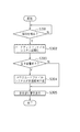
続いて、メモリカード110が装着されており、メモリカード記録モードであるデジタルカメラ100に、USBケーブル111、即ちハードディスク112が接続された場合の処理について図3に従って説明する。
Next, processing when the
ステップS301では、ハードディスク112の装着検出処理が行われる。実際には、USBケーブル111と物理的かつ電気的に接続された場合、USBインタフェース回路(図示せず)によって割り込み処理が発生し、ハードディスクドライバ205がハードディスク112が接続されたことを検知する。
In step S301, a mounting detection process for the
ステップS302では、ハードディスクドライバ205からの通知によって、ハードディスクファイルシステム204が初期化処理を行う。即ち、ハードディスクファイルシステム204は、ハードディスク111に対して情報の取得を行い、全体の容量や、記録されているファイル、ディレクトリ情報等を読出し、ファイルシステムの初期化を行う。
In step S302, the hard
ステップS303では、メモリカードファイルシステム202は、ハードディスクファイルシステム204からの指示に基づき、メモリカード110の中に保護領域に設定するだけの空き容量が存在するかどうかの判断を行う。
In step S <b> 303, the memory
メモリカード110内に開き領域が存在する場合、ステップS304では、ハードディスクファイルシステム204が、メモリカードファイルシステム202に対して、メモリカード110の空き容量のうち64メガバイトを記録禁止に設定する。後述するが、この領域は撮影中にハードディスク112が不意に抜けてしまった場合の直後の撮影データを記録するための保護領域である。
If there is an open area in the
メモリカードファイルシステム202は、メモリカード110がデジタルカメラ100に装着された時あるいは上位アプリケーションによって指令を受けた時に初期化を行う。このとき、メモリカードファイルシステム202はメモリカード110に対してファイル情報の取得を行う(例えば、ファイルアロケーションテーブル)。またこのとき、メモリカードファイルシステム202はメモリカード110の全体容量、空き容量についての情報も取得する。
The memory
ステップS304では、メモリカードファイルシステム202は、自身が管理しているメモリカード110の空き容量情報に対して64メガバイトを減算するだけであり、メモリカードドライバ203及びメモリカード110に対しての処理は全く行わない。これにより、上位の撮影記録アプリケーション201に対しては、実際のメモリカード110の空き容量が少なくなったように見える。本実施形態においては、この保護領域に設定する容量を64メガバイトとするが、勿論これに限らない。
In step S304, the memory
また、ステップS304では、表示部108はハードディスク112が接続されたことをユーザに通知してもよい。
In step S304, the
一方、空き容量が存在せず、保護領域を確保できない場合は、ステップS305にて、表示部108が警告表示を行い、ユーザに対してメモリカード110内に保護領域が作成されなかったことを通知する。以上がハードディスク112が接続された場合の一連の処理である。これにより、ステップS303にて記録禁止領域が設定された場合は、撮影記録アプリケーション201からはメモリカード110に対して撮影したデジタル画像データの記録可能容量が少なくなる。
On the other hand, if there is no free space and the protected area cannot be secured, the
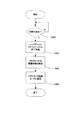
続いて、図3に従ってメモリカード110内に保護領域をもつデジタルカメラ100がハードディスク記録モード又は同時記録モードにある場合に、USBケーブル111が抜けてしまった場合の処理について図4に従って説明する。
Next, the processing when the
ステップS401では、ハードディスク112との接続の切断検出が行われる。処理はステップS301と同じであり、USBケーブル111が物理的かつ電気的に接続された場合、USBインタフェース回路によって割り込み処理が発生し、ハードディスクドライバ205がハードディスク112との接続が切断されたことを検知する。
In step S401, disconnection detection with the
ステップS402では、ハードディスクドライバ205からの通知によって、ハードディスクファイルシステム204がファイル、ディレクトリ等のアロケーション情報を解放し、ファイルシステムの終了処理を行う。
In step S402, the hard
ステップS403では、さらにハードディスクファイルシステム204が、メモリカードファイルシステム202の保護領域を解放する。メモリカードファイルシステム202は、自身が管理しているメモリカード110の空き容量情報に対して64メガバイトを加算するだけであり、メモリカードドライバ203及びメモリカード110に対しての処理は全く行わない。これにより、上位の撮影記録アプリケーション201に対しては、実際のメモリカード110の空き容量が多くなったように見える。
In step S403, the hard
続いてステップS404では、ハードディスク112接続の切断通知を受けた撮影記録アプリケーション201が撮影記録モードをメモリカード記録モードに変更する。以上が、USBケーブル111が抜かれた場合の一連の処理である。これにより、撮影記録アプリケーション201は、ハードディスク記録モードにおいてUSBケーブル111が抜かれた場合でも、その後撮影したデジタル画像データをメモリカード110内の保護領域に対して確実に記録する。
Subsequently, in step S404, the photographing /
−第2の実施形態−
次に、本発明の第2の実施形態について説明する。以上、第1の実施形態において、単一のメモリカード110を装着したデジタルカメラ100において説明を行ったが、本発明においてはデジタルカメラ100がハードディスク112の他に複数の記録媒体を有する場合においても適用可能である。以下、第2の実施形態において、デジタルカメラ100がメモリカードA503、およびメモリカードB504を装着可能な例を第2の実施形態として説明する。
-Second Embodiment-
Next, a second embodiment of the present invention will be described. In the first embodiment, the
図5は、本発明の第2の実施形態に係るデジタルカメラ100の内部構成を示すブロック図である。メモリカードA記録部501はメモリカードA503と物理的かつ電気的に接続され、撮影したデジタル画像データ等をメモリカードA503に書き込み、格納された画像データを読み出す。同様にメモリカードB記録部502はメモリカードB504と物理的かつ電気的に接続され、撮影したデジタル画像データ等をメモリカードB504に書き込み、格納された画像データを読み出す。その他のブロックについては、第1の実施形態との差異は無い。
FIG. 5 is a block diagram showing an internal configuration of the
続いてデジタルカメラ100の撮影記録モードについて説明する。デジタルカメラ100は撮影データの記録先に応じて五つの撮影記録モードをもつ。一つ目はメモリカードA記録モード、二つ目はメモリカードB記録モード、三つ目はハードディスク記録モード、四つ目はメモリカードAハードディスク同時記録モード、五つ目はメモリカードBハードディスク同時記録モードである。
Next, the shooting / recording mode of the
メモリカードA記録モードは、撮像部106によって出力され、RAM103に展開されたデジタル画像データを、メモリカードA記録部501がメモリカードA503に記録を行うモードである。メモリカードB記録モードは、メモリカードB記録部502がメモリカードB504にデジタル画像データの記録を行うモードである。ハードディスク記録モードは、USBインタフェース部105がハードディスク112にUSBプロトコルを使用してデジタル画像データを送信して記録を行うモードである。メモリカードAハードディスク同時記録モードは、上記メモリカードA503とハードディスク112とに対するデジタル画像データの記録を同時に行うモードである。メモリカードBハードディスク同時記録モードは、上記メモリカードB504とハードディスク112とに対するデジタル画像データの記録を同時に行うモードである。これら五つのモードは通常ユーザによって指定可能であり、操作部107からの入力によってモードの変更が行われる。
The memory card A recording mode is a mode in which the memory card
図6は、本発明の第2の実施形態における、撮影したデジタル画像データを記録する処理に関わるソフトウェアのモジュール構成を示したものである。メモリカードAファイルシステム601及びメモリカードBファイルシステム603は、それぞれメモリカードA503及びメモリカードB504に記録されているデジタル画像データのファイル及びディレクトリ情報を管理する。そして、メモリカードAファイルシステム601は、撮影記録アプリケーション201からの指令に基づき、メモリカードAドライバ602に対してファイル、ディレクトリ単位でのデータの読み書き等を行う。メモリカードBファイルシステム602は、撮影記録アプリケーション201からの指令に基づく、メモリカードBドライバ604に対してファイル、ディレクトリ単位でのデータの読み書き等を行う。
FIG. 6 shows a module configuration of software related to processing for recording photographed digital image data in the second embodiment of the present invention. The memory card
メモリカードAドライバ602及びメモリカードBドライバ604は、それぞれメモリカードA503及びメモリカードB504の接続の検出、並びに上位ファイルシステムの指令に基づき、データの読み書きを行うモジュールである。その他のモジュールについては第1の実施形態との差異は無い。
The memory
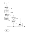
続いて、メモリカードA記録モード又はメモリカードB記録モードであるデジタルカメラ100に、USBケーブル111、すなわちハードディスク112が接続された場合の処理について図7に従って説明する。
Next, processing when the
ステップS301、ステップS302については第1の実施形態との差異はない。ステップS701において、メモリカードAファイルシステム601は、メモリカードA503内に所定サイズの保護領域が生成可能かどうかの判断を行う。本実施形態においても所定サイズを64メガバイトとする。生成可能である場合は、ステップS702にてメモリカードAファイルシステム601が保護領域を生成する。メモリカードAファイルシステム601は、自身が管理しているメモリカードA503の空き容量情報に対して64メガバイトを減算するだけであり、メモリカードAドライバ602及びメモリカードA503に対しての処理は全く行わない。以上で処理は終了する。
Steps S301 and S302 are not different from those of the first embodiment. In step S701, the memory card
一方、ステップS701において、生成不可能と判断された場合は、ステップS703にて、メモリカードBファイルシステム603は、メモリカードB内に64メガバイトの保護領域が生成可能かどうかの判断を行う。生成可能である場合は、ステップS704にてメモリカードBファイルシステム603が保護領域を生成する。メモリカードBファイルシステム603は、自身が管理しているメモリカードB504の空き容量情報に対して64メガバイトを減算するだけであり、メモリカードBドライバ604及びメモリカードB504に対しての処理は全く行わない。以上で処理は終了する。
On the other hand, if it is determined in step S701 that it cannot be generated, the memory card
一方、ステップS703において、生成不可能と判断された場合は、処理はステップS305に進む。ステップS305については第1の実施形態との差異はない。以上で処理を終了する。 On the other hand, if it is determined in step S703 that generation is not possible, the process proceeds to step S305. Step S305 is not different from the first embodiment. The process ends here.
続いて、USBケーブル111が抜けてしまった場合の処理について図8に従って説明する。ここでは、メモリカードA503又はメモリカードB504内に保護領域をもつデジタルカメラ100が、ハードディスク記録モード、メモリカードAハードディスク同時記録モード及びメモリカードBハードディスク同時記録モードのいずれかにある。
Next, processing when the
ステップS401、ステップS402については第1の実施形態との差異はない。ステップS801では、ステップS702又はステップS704で生成していた保護領域が解放される。該当するメモリカードファイルシステムは、自身が管理しているメモリカードの空き容量情報に対して64メガバイトを加算するだけであり、メモリカードドライバ及びメモリカードに対しての処理は全く行わない。 Steps S401 and S402 are not different from those of the first embodiment. In step S801, the protected area generated in step S702 or step S704 is released. The corresponding memory card file system only adds 64 megabytes to the free space information of the memory card managed by itself, and does not perform any processing on the memory card driver and the memory card.
ステップS801により、上位の撮影記録アプリケーション201に対しては、実際のメモリカードの空き容量が多くなったように見える。続いてステップS802では、ハードディスク112接続の切断通知を受けた撮影記録アプリケーション201が撮影デジタル画像データの記録先を、保護領域を生成したメモリカードに設定する。即ち、記録モードをメモリカードA記録モード又はメモリカードB記録モードに変更する。以上が、USBケーブル111が抜かれた場合の一連の処理である。これにより、撮影記録アプリケーション201は、ハードディスク記録モードにおいてUSBケーブル111が抜かれた場合でも、その後撮影したデジタル画像データをメモリカード内の保護領域に対して確実に記録する。
As a result of step S801, it appears to the upper recording /
以上、第1又は第2の実施形態で示した処理により、ハードディスクに撮影記録を行っている状況において、USBケーブル111が抜けてしまった場合でも画像データを、予めメモリカード内に用意しておいた保護領域に対して確実に記録することが可能である。従って、USBケーブル111が抜けた直後でも撮影動作を継続することが可能であり重要なシャッタチャンスを逃すことを防止できる。また、ハードディスクとともにメモリカードでも同時に撮影記録を行い、且つメモリカードに記録可能な空き容量が無くなり、USBケーブル111が抜けてしまった場合でも、同様に画像データを保護領域に対して確実に記録することが可能である。また、撮影動作を継続することもできる。
As described above, the image data is prepared in the memory card in advance even when the
また、保護領域として確保する領域のサイズは、USBケーブル111が抜かれた場合に保険として確保しておくべきサイズであり、現実的にはデジタル画像データ数枚分であれば十分と考えられる。具体的には、撮影動画像データのとり得る最大値のn倍、8×nバイトの固定サイズ等が挙げられる。これはメモリカードの全体サイズに比べて少ないサイズであるため、ハードディスク112装着により自動的にメモリカードの容量が少なくなったとしても、ユーザにとってはあまり気にならない量と考えられる。なお、メモリカードの一部に限られず、メモリカード全体を空き領域として確保してもよい。また、上述した実施形態では、ステップS305等において、ハードディスク接続時にユーザに対して警告を表示し、保護領域の作成を促している。これにより、重要なシャッタチャンスではないときにメモリカード内のデータを別の記録媒体にコピーしたり、不要なデータを消去するなどして、事前に余裕を持って保護領域の準備をすることが自然と可能になる。
In addition, the size of the area to be secured as the protection area is a size that should be secured as insurance when the
また、第1又は第2の実施形態では、デジタルカメラが接続する記録媒体としてメモリカード、およびハードディスクとしたが、もちろんこの限りではない。本発明に原則としてどの記録媒体に対しても適用可能であり、光ディスクや内蔵の揮発メモリなどでもよい。 In the first or second embodiment, a memory card and a hard disk are used as recording media to which the digital camera is connected. In principle, the present invention can be applied to any recording medium, and may be an optical disk or a built-in volatile memory.
また、第1又は第2の実施形態では、保護領域を生成する記録媒体としてメモリカードのみとしたが、これについてもこの限りではない。例えば複数のメモリカードが装着可能な場合は、複数のメモリカードから保護領域を生成可能なメモリカードをサーチ選択し、選択したメモリカード内に保護領域を生成することもできる。また、一つの保護領域を複数のメモリカードに亘って生成したりすることも可能である。 In the first or second embodiment, only the memory card is used as the recording medium for generating the protection area, but this is not limited thereto. For example, when a plurality of memory cards can be mounted, it is possible to search and select a memory card that can generate a protection area from the plurality of memory cards, and to generate a protection area in the selected memory card. It is also possible to generate one protected area across a plurality of memory cards.
また、第1又は第2の実施形態では、ファイルシステムについてメモリカードファイルシステム、ハードディスクファイルシステムのように明示的に分類している。この他に、一つのファイルシステムが複数のメモリカードとハードディスクの全てのファイル情報を管理し、撮影記録アプリケーション201に対して共通のインタフェースを提供する構成においても本発明が適用可能であることは言うまでも無い。
In the first or second embodiment, the file system is explicitly classified as a memory card file system or a hard disk file system. In addition, it can be said that the present invention can also be applied to a configuration in which one file system manages all file information of a plurality of memory cards and hard disks and provides a common interface to the
さらに、ハードディスク111とデジタルカメラ100とを接続するための回線のインタフェースは、USBインタフェースに限らず、IEEE1394インタフェース、Ethernet(登録商標)インタフェース、IEEE802.11インタフェース等であってもよい。
Further, the line interface for connecting the
また、本発明の目的は、前述した実施形態の機能を実現するソフトウェアのプログラムコードを記録した記憶媒体をシステム或いは装置に供給し、そのシステム等のコンピュータが記憶媒体からプログラムコードを読み出し実行することによっても達成される。 Another object of the present invention is to supply a storage medium storing software program codes for realizing the functions of the above-described embodiments to a system or apparatus, and a computer such as the system reads and executes the program codes from the storage medium. Is also achieved.
この場合、記憶媒体から読み出されたプログラムコード自体が前述した実施形態の機能を実現することになり、プログラムコード自体及びそのプログラムコードを記憶した記憶媒体は本発明を構成することになる。 In this case, the program code itself read from the storage medium realizes the functions of the above-described embodiments, and the program code itself and the storage medium storing the program code constitute the present invention.
プログラムコードを供給するための記憶媒体としては、例えば、フレキシブルディスク、ハードディスク、光ディスク、光磁気ディスク、CD−ROM、CD−R、磁気テープ、不揮発性のメモリカード、ROM等を用いることができる。 As a storage medium for supplying the program code, for example, a flexible disk, a hard disk, an optical disk, a magneto-optical disk, a CD-ROM, a CD-R, a magnetic tape, a nonvolatile memory card, a ROM, or the like can be used.
また、コンピュータが読み出したプログラムコードの指示に基づき、コンピュータ上で稼動しているOS等が実際の処理の一部又は全部を行い、その処理によって前述した実施形態の機能が実現される場合も含まれる。 In addition, the case where the functions of the above-described embodiment are realized by performing part or all of the actual processing by an OS or the like running on the computer based on the instruction of the program code read by the computer. It is.
さらに、記憶媒体から読み出されたプログラムコードが、コンピュータに接続された機能拡張ユニット等に備わるメモリに書込まれた後、そのプログラムコードの指示に基づきCPU等が実際の処理を行い、前述した実施形態の機能が実現される場合も含まれる。 Further, after the program code read from the storage medium is written in a memory provided in a function expansion unit connected to the computer, the CPU or the like performs actual processing based on the instruction of the program code, and the above-described processing is performed. The case where the functions of the embodiment are realized is also included.
100 デジタルカメラ
101 CPU
102 ROM
103 RAM
104 メモリカード記録部
105 USBインタフェース部
106 撮像部
107 操作部
108 表示部
109 内部バス
110 メモリカード
111 USBケーブル
112 ハードディスク
201 撮影記録アプリケーション
202 メモリカードファイルシステム
203 メモリカードドライバ
204 ハードディスクファイルシステム
205 ハードディスクドライバ
501 メモリカードA記録部
502 メモリカードB記録部
503 メモリカードA
504 メモリカードB
601 メモリカードAファイルシステム
602 メモリカードAドライバ
603 メモリカードBファイルシステム
604 メモリカードBドライバ
100
102 ROM
103 RAM
DESCRIPTION OF
504 Memory card B
601 Memory card
Claims (13)
第1の記録領域内に所定のサイズの空き領域を予め確保する領域確保手段と、
少なくとも第2の記憶領域にデータを記録するモードにおいて、前記第2の記録領域に対するデータの記録が不可となったことを検知する検知手段と、
前記検知手段により前記第2の記録領域に対するデータの記録が不可であることが検知された場合、前記第2の記録領域から前記第1の記録領域内の空き領域にデータを記録できるよう制御するデータ記録制御手段とを有することを特徴とする記録装置。 A recording apparatus capable of recording data in two or more recording areas,
Area securing means for securing a free area of a predetermined size in the first recording area in advance;
Detecting means for detecting that recording of data in the second recording area is disabled in a mode for recording data in at least the second storage area;
Control is performed so that data can be recorded from the second recording area to an empty area in the first recording area when it is detected by the detecting means that data cannot be recorded in the second recording area. And a data recording control means.
第1の記録領域内に所定のサイズの空き領域を予め確保する領域確保ステップと、
少なくとも第2の記憶領域にデータを記録するモードにおいて、前記第2の記録領域に対するデータの記録が不可となったことを検知する検知ステップと、
前記検知ステップにより前記第2の記録領域に対するデータの記録が不可であることが検知された場合、前記第2の記録領域から前記第1の記録領域内の空き領域にデータを記録できるよう制御するデータ記録制御ステップとを含むことを特徴とする記録装置の制御方法。 A control method of a recording apparatus capable of recording data in two or more recording areas,
An area securing step for securing a free area of a predetermined size in the first recording area in advance;
A detection step of detecting that recording of data in the second recording area is disabled in a mode for recording data in at least the second storage area;
When it is detected by the detection step that data cannot be recorded in the second recording area, control is performed so that data can be recorded from the second recording area to an empty area in the first recording area. A recording apparatus control method comprising: a data recording control step.
第1の記録領域内に所定のサイズの空き領域を予め確保する領域確保ステップと、
少なくとも第2の記憶領域にデータを記録するモードにおいて、前記第2の記録領域に対するデータの記録が不可となったことを検知する検知ステップと、
前記検知ステップにより前記第2の記録領域に対するデータの記録が不可であることが検知された場合、前記第2の記録領域から前記第1の記録領域内の空き領域にデータを記録できるよう制御するデータ記録制御ステップとをコンピュータに実行させるためのプログラム。 A program for causing a computer to execute a control method of a recording apparatus capable of recording data in two or more recording areas,
An area securing step for securing a free area of a predetermined size in the first recording area in advance;
A detection step of detecting that recording of data in the second recording area is disabled in a mode for recording data in at least the second storage area;
When it is detected by the detection step that data cannot be recorded in the second recording area, control is performed so that data can be recorded from the second recording area to an empty area in the first recording area. A program for causing a computer to execute the data recording control step.
第1の記録領域内に所定のサイズの空き領域を予め確保する領域確保ステップと、
少なくとも第2の記憶領域にデータを記録するモードにおいて、前記第2の記録領域に対するデータの記録が不可となったことを検知する検知ステップと、
前記検知ステップにより前記第2の記録領域に対するデータの記録が不可であることが検知された場合、前記第2の記録領域から前記第1の記録領域内の空き領域にデータを記録できるよう制御するデータ記録制御ステップとをコンピュータに実行させるためのプログラムを記録したコンピュータ読み取り可能な記録媒体。 A computer-readable recording medium recording a program for causing a computer to execute a control method of a recording apparatus capable of recording data in two or more recording areas,
An area securing step for securing a free area of a predetermined size in the first recording area in advance;
A detection step of detecting that recording of data in the second recording area is disabled in a mode for recording data in at least the second storage area;
When it is detected by the detection step that data cannot be recorded in the second recording area, control is performed so that data can be recorded from the second recording area to an empty area in the first recording area. A computer-readable recording medium recording a program for causing a computer to execute a data recording control step.
Priority Applications (2)
| Application Number | Priority Date | Filing Date | Title |
|---|---|---|---|
| JP2006205323A JP4745908B2 (en) | 2006-07-27 | 2006-07-27 | Recording apparatus and control method thereof |
| US11/780,986 US7868931B2 (en) | 2006-07-27 | 2007-07-20 | Data recording apparatus and control method |
Applications Claiming Priority (1)
| Application Number | Priority Date | Filing Date | Title |
|---|---|---|---|
| JP2006205323A JP4745908B2 (en) | 2006-07-27 | 2006-07-27 | Recording apparatus and control method thereof |
Publications (3)
| Publication Number | Publication Date |
|---|---|
| JP2008035131A JP2008035131A (en) | 2008-02-14 |
| JP2008035131A5 JP2008035131A5 (en) | 2009-09-10 |
| JP4745908B2 true JP4745908B2 (en) | 2011-08-10 |
Family
ID=38986118
Family Applications (1)
| Application Number | Title | Priority Date | Filing Date |
|---|---|---|---|
| JP2006205323A Active JP4745908B2 (en) | 2006-07-27 | 2006-07-27 | Recording apparatus and control method thereof |
Country Status (2)
| Country | Link |
|---|---|
| US (1) | US7868931B2 (en) |
| JP (1) | JP4745908B2 (en) |
Families Citing this family (1)
| Publication number | Priority date | Publication date | Assignee | Title |
|---|---|---|---|---|
| JP6057701B2 (en) * | 2012-12-26 | 2017-01-11 | キヤノン株式会社 | Recording apparatus and control method thereof |
Family Cites Families (10)
| Publication number | Priority date | Publication date | Assignee | Title |
|---|---|---|---|---|
| JP3663956B2 (en) * | 1999-03-01 | 2005-06-22 | トヨタ自動車株式会社 | In-vehicle information processing equipment |
| JP2001008147A (en) * | 1999-06-22 | 2001-01-12 | Olympus Optical Co Ltd | Electronic camera |
| JP3610263B2 (en) | 1999-07-22 | 2005-01-12 | オリンパス株式会社 | Electronic camera |
| US20020041330A1 (en) * | 2000-10-10 | 2002-04-11 | Konica Corporation | Electronic camera |
| JP3984909B2 (en) * | 2002-12-13 | 2007-10-03 | キヤノン株式会社 | Imaging device |
| JP2004241104A (en) * | 2003-01-15 | 2004-08-26 | Matsushita Electric Ind Co Ltd | Digital video recorder, its driving method, and program |
| JP2005080008A (en) * | 2003-09-01 | 2005-03-24 | Fuji Photo Film Co Ltd | Imaging apparatus and data management method thereof |
| US20050174443A1 (en) * | 2004-02-09 | 2005-08-11 | Ikuo Niimura | Image sensing apparatus and method of controlling same |
| JP2006094230A (en) * | 2004-09-24 | 2006-04-06 | Toshiba Corp | Imaging apparatus, setting method, and information processing method |
| US20060152602A1 (en) * | 2005-01-13 | 2006-07-13 | Canon Kabushiki Kaisha | Recording and reproducing apparatus |
-
2006
- 2006-07-27 JP JP2006205323A patent/JP4745908B2/en active Active
-
2007
- 2007-07-20 US US11/780,986 patent/US7868931B2/en not_active Expired - Fee Related
Also Published As
| Publication number | Publication date |
|---|---|
| JP2008035131A (en) | 2008-02-14 |
| US20080025160A1 (en) | 2008-01-31 |
| US7868931B2 (en) | 2011-01-11 |
Similar Documents
| Publication | Publication Date | Title |
|---|---|---|
| JP4154431B2 (en) | Imaging apparatus and display control method | |
| US7545413B2 (en) | Method and apparatus for displaying images using duplex thumbnail mode | |
| WO1999060786A1 (en) | Method and apparatus to control the behavior of a digital camera by detecting connectivity to a universal serial bus | |
| US20050174446A1 (en) | Image sensing apparatus | |
| JP6271917B2 (en) | Image recording apparatus and imaging apparatus | |
| JP4939203B2 (en) | Display control device, imaging device, and control method | |
| JP4745908B2 (en) | Recording apparatus and control method thereof | |
| US7657700B2 (en) | Recording device, recording-medium-management method, program of recording-medium-management method, and recording medium recording program of recording-medium-management method | |
| KR101836093B1 (en) | Black Box For Vehicle Capable of transferring of internal data to External Device | |
| US6825950B1 (en) | Image reproduction apparatus, control method thereof, printing information generation method, and storage medium | |
| JP2008141725A (en) | Camera, and file management method used for the camera | |
| JP4261815B2 (en) | Imaging device | |
| JP4981478B2 (en) | Imaging device | |
| JP4878456B2 (en) | Recording medium and imaging apparatus | |
| JP2007221722A (en) | Image processing apparatus and control method thereof | |
| JP4407748B2 (en) | Imaging apparatus, communication control method, and program | |
| JP2004289307A (en) | Image recording and reproducing apparatus | |
| JP5950798B2 (en) | Recording apparatus and control method thereof | |
| JP2006039203A (en) | Imaging apparatus, and its control method | |
| US20230396731A1 (en) | Image reproduction apparatus, control method thereof, and storage medium | |
| JP2003224809A (en) | Data recording apparatus | |
| JP2007049283A (en) | Camera and information processor | |
| JP2011234291A (en) | Imaging device, imaging method, and program | |
| JP2006109137A (en) | Image processing device | |
| JP2023179219A (en) | Image reproduction device, control method of the same, program and storage medium |
Legal Events
| Date | Code | Title | Description |
|---|---|---|---|
| A521 | Request for written amendment filed |
Free format text: JAPANESE INTERMEDIATE CODE: A523 Effective date: 20090727 |
|
| A621 | Written request for application examination |
Free format text: JAPANESE INTERMEDIATE CODE: A621 Effective date: 20090727 |
|
| A977 | Report on retrieval |
Free format text: JAPANESE INTERMEDIATE CODE: A971007 Effective date: 20110406 |
|
| TRDD | Decision of grant or rejection written | ||
| A01 | Written decision to grant a patent or to grant a registration (utility model) |
Free format text: JAPANESE INTERMEDIATE CODE: A01 Effective date: 20110510 |
|
| A01 | Written decision to grant a patent or to grant a registration (utility model) |
Free format text: JAPANESE INTERMEDIATE CODE: A01 |
|
| A61 | First payment of annual fees (during grant procedure) |
Free format text: JAPANESE INTERMEDIATE CODE: A61 Effective date: 20110512 |
|
| FPAY | Renewal fee payment (event date is renewal date of database) |
Free format text: PAYMENT UNTIL: 20140520 Year of fee payment: 3 |
|
| R150 | Certificate of patent or registration of utility model |
Ref document number: 4745908 Country of ref document: JP Free format text: JAPANESE INTERMEDIATE CODE: R150 Free format text: JAPANESE INTERMEDIATE CODE: R150 |