JP2004241104A - Digital video recorder, its driving method, and program - Google Patents
Digital video recorder, its driving method, and program Download PDFInfo
- Publication number
- JP2004241104A JP2004241104A JP2004002618A JP2004002618A JP2004241104A JP 2004241104 A JP2004241104 A JP 2004241104A JP 2004002618 A JP2004002618 A JP 2004002618A JP 2004002618 A JP2004002618 A JP 2004002618A JP 2004241104 A JP2004241104 A JP 2004241104A
- Authority
- JP
- Japan
- Prior art keywords
- data
- recording medium
- recording
- recorded
- digital video
- Prior art date
- Legal status (The legal status is an assumption and is not a legal conclusion. Google has not performed a legal analysis and makes no representation as to the accuracy of the status listed.)
- Pending
Links
Images


Landscapes
- Television Signal Processing For Recording (AREA)
- Signal Processing For Digital Recording And Reproducing (AREA)
Abstract
Description
本発明は、放送されているTV番組(動画/音声などのデータ)をリアルタイムで記録媒体に記録することができるデジタルビデオレコーダに関している。 The present invention relates to a digital video recorder capable of recording a broadcasted TV program (data such as moving image / audio) on a recording medium in real time.
なお、本明細書における「デジタルビデオレコーダ」の用語は、放送データの記録に用いられる据え置き型のデジタルビデオレコーダに限定されず、カムコーダや小型携帯端末などの持ち運び可能な電子機器をも広く含むものとする。 Note that the term “digital video recorder” in this specification is not limited to a stationary digital video recorder used for recording broadcast data, but also includes portable electronic devices such as camcorders and small portable terminals. .
光ディスクおよび/またはハードディスクなどの記録媒体にデジタルデータを記録するデジタルビデオレコーダが急速に普及しつつある。それらの中でも、光ディスクドライブおよびハードディスクドライブ(HDD)の両方を備えたハイブリッド型のデジタルビデオレコーダが注目されている。ハイブリッド型デジタルビデオレコーダでは、ユーザが保存したいデータを最初に例えばハードディスクに記録し、その後にハードディスク上のデータを光ディスクに転送することができる。このようなデジタルビデオレコーダのハードディスクは、デジタルビデオレコーダ内のHDDに固定されているため、取り外しが容易には行なえないが、光ディスクは取り外し可能である。このため、複数の光ディスクから任意に選択された1つをデジタルビデオレコーダにロードすれば、いつでも、ハードディスクに記録されているデータを光ディスクに転送し、デジタルビデオレコーダの外で保存することができる。このようなハイブリッド型のデジタルビデオレコーダを用いると、種々のデータ(動画、静止画、音声などのデータ)をハードディスクおよび/または光ディスクに記録することができる。 Digital video recorders for recording digital data on recording media such as optical disks and / or hard disks are rapidly becoming widespread. Among them, a hybrid digital video recorder provided with both an optical disk drive and a hard disk drive (HDD) has attracted attention. In a hybrid digital video recorder, data that a user wants to store can be first recorded on, for example, a hard disk, and then the data on the hard disk can be transferred to the optical disk. Since the hard disk of such a digital video recorder is fixed to the HDD in the digital video recorder, it cannot be easily removed, but the optical disk is removable. Therefore, by loading one of a plurality of optical discs arbitrarily selected into the digital video recorder, the data recorded on the hard disc can be transferred to the optical disc at any time and stored outside the digital video recorder. With such a hybrid digital video recorder, various data (data such as moving images, still images, and audio) can be recorded on a hard disk and / or an optical disk.
このようなデジタルビデオレコーダまたはデジタルビデオカメラに内蔵されている光ディスクドライブの多くは、録画されるデータの保護のための欠陥処理機能を備えている。例えば特許文献1や特許文献2に開示されているデジタルビデオレコーダでは、光ディスク上に予め交代領域を設けておき、光ディスク上にディフェクトがあった場合、ディフェクトが存在する位置の周辺領域へのデータ記録は行なわず、その代わりに交代領域へのデータを記録する。光ディスク上のディフェトの典型例は、ディスク表面のゴミまたはひっかき傷などである。
Many of the optical disk drives built in such digital video recorders or digital video cameras have a defect processing function for protecting recorded data. For example, in the digital video recorders disclosed in
このような欠陥処理を行なうことにより、ディフェクトなどによる記録情報の欠損が抑制され、信頼性の高い情報の記録・蓄積が可能となる。 By performing such a defect process, loss of recorded information due to a defect or the like is suppressed, and highly reliable information can be recorded and stored.
また、ハイブリッド型のデジタルビデオレコーダを用いて放送データを光ディスクに記録する場合、そのデータを光ディスクに直接的に記録する前に、デジタルビデオレコーダに内蔵されたハードディスクに一時的に記録することが行なわれる。ハードディスクに記録された放送データは、その後に読み出され、光ディスクに書き込まれる。このような記録方式では、ハードディスクが光ディスクへの記録に対するキャッシュメモリとして利用されている。特許文献3および特許文献4は、レコーダに固定された記録媒体をキャッシュメモリとして用いる従来技術を開示している。
上記の交代処理は、光ディスク上にディフェクトが存在することが予め予測されるときや、光ディスクへの書き込みビジー状態の解除待ちに対しては有効に機能する。しかしながら、突発的に発生する書き込み異常に対しては、充分に機能しない。 The above-described replacement process functions effectively when it is predicted in advance that a defect exists on the optical disk, or when the optical disk is waiting to release a busy state of writing on the optical disk. However, it does not function sufficiently against sudden write errors.
突発的に発生する書き込み異常の典型的な例は、トラッキング外れである。トラッキング外れの要因としては、(1)光ディスク表面のディフェクト、(2)外的なショック、および、(3)光ディスクそのものの品質(例えば、偏心、面反りが大きい)などの要因が挙げられる。 A typical example of a sudden write error is tracking loss. Factors of tracking loss include (1) defects on the optical disk surface, (2) external shocks, and (3) quality of the optical disk itself (for example, large eccentricity and warpage).
最近、コストが安価であるという理由から、DVD−Rなどの1回記録のみ可能な光ディスクの需要が急増している。このような安価な追記型光ディスクの場合、書き込み異常が高い頻度で発生する傾向にある。 Recently, demand for optical discs such as DVD-Rs that can be recorded only once is rapidly increasing because of their low cost. In the case of such an inexpensive write-once optical disc, a writing error tends to occur at a high frequency.
放送データなどのデータを記録している最中に書き込み異常が発生した場合、単なるディフェクト処理などとは異なり、データの欠損量は予め光ディスク上に確保されている交代領域の容量を大きく上回ることが多い。また、交代領域の容量が十分であったとしても、当該領域にアクセスする時間的余裕が無いことが問題である。 If a write error occurs while recording data such as broadcast data, the amount of data loss can greatly exceed the capacity of the spare area previously secured on the optical disc, unlike mere defect processing. Many. Further, even if the capacity of the replacement area is sufficient, there is a problem that there is not enough time to access the area.
光ディスクを単にバックアップとして用いる場合、例えばハードディスク内の情報をアーカイバルにセーブする目的で光ディスクを使用する場合には、こういった問題はあまり発生しない。交代領域へのアクセスが増えても、単にバックアップ完了までの時間が長くなるだけである。また交代領域が不足するほどの書き込み異常が発生しても、元のデータはハードディスク上に残っているので、光ディスクを交換した後、再度バックアップをやり直せばよいからである。 When the optical disk is simply used as a backup, for example, when the optical disk is used for the purpose of archivally saving information in the hard disk, such a problem does not occur much. Even if the number of accesses to the replacement area increases, the time until the completion of the backup simply increases. Also, even if a write error occurs such that the replacement area becomes insufficient, the original data remains on the hard disk, so that after the optical disk is replaced, the backup may be performed again.
書き込み異常が問題になるのは、TV番組のような放送データをリアルタイムで蓄積する場合や、撮影中のビデオカメラにおける動画・音声データを光ディスクに記録する場合である。これらの信号は非インタラクティブ的であり、データを蓄積(記録)する側(スレーブ)の事情に応じて、データ供給源(マスター)の動作を制限することが認められない。このような場合、記録動作中に一旦書き損じが生じると、これを処理している間にも放送データなどのリアルタイムデータは途絶えること無く送られてくる。このため、交代処理が滞ると、それがそのまま情報欠損を引き起こすことになる。 The problem of abnormal writing occurs when broadcast data such as a TV program is stored in real time, or when moving image / audio data from a video camera during shooting is recorded on an optical disk. These signals are non-interactive, and it is not allowed to limit the operation of the data source (master) depending on the situation of the data storage (recording) side (slave). In such a case, once a writing error occurs during the recording operation, real-time data such as broadcast data is continuously transmitted even while the writing is being processed. For this reason, if the replacement process is delayed, it causes information loss as it is.
なお、放送番組を直接光ディスクに保存せずに、一旦ハードディスクやDRAMにキャッシュしてから光ディスクに保存すれば、こういった課題の大半は回避されるであろう。しかし、このようにすると、放送番組などを最初から光ディスクのみに保存しておきたい場合ですら、光ディスクとハードディスクの両方への記録を常に行う必要がある。このためには、2種類のドライブを常に動作させる必要があり、省電力という観点から好ましくない。省電力は、電池などの電源で動作するカムコーダなどのビデオカメラにおいて特に重要な課題である。 It should be noted that if the broadcast program is not directly stored on the optical disk but is cached on a hard disk or DRAM and then stored on the optical disk, most of these problems will be avoided. However, in this case, even when it is desired to store a broadcast program or the like only on the optical disk from the beginning, it is necessary to always record the program on both the optical disk and the hard disk. For this purpose, it is necessary to always operate two types of drives, which is not preferable from the viewpoint of power saving. Power saving is a particularly important issue for video cameras such as camcorders that operate on a power supply such as a battery.
一方、ハードディスクの代わりにDRAMをキャッシュメモリとして用いると、その価格に比べて個々のDRAMの容量が小さいため、放送番組のように容量の大きなデータのキャッシュとして使用することは実用的ではない。 On the other hand, if a DRAM is used as a cache memory instead of a hard disk, the capacity of each DRAM is smaller than its price, so that it is not practical to use it as a cache for large-capacity data such as a broadcast program.
本発明は、上記事情に鑑みてなされたものであり、その目的は、放送番組や撮像中の映像・音声データを光ディスクに記録している最中に記録異常が発生しても、番組内容や撮像内容を欠損させることなく収録することができるデジタルビデオレコーダを提供することにある。 SUMMARY OF THE INVENTION The present invention has been made in view of the above circumstances, and has as its object the purpose of providing a program content and a broadcast program even when recording abnormalities occur during recording of video / audio data being captured on an optical disc. It is an object of the present invention to provide a digital video recorder capable of recording without losing the imaged content.
本発明のデジタルビデオレコーダは、第1記録媒体および第2記録媒体のうちの選択された記録媒体にデータを記録することができるデジタルビデオレコーダであって、前記第1記録媒体にデータを記録している途中で異常が発生したとき、前記異常を検知する異常状態検出手段とを備え、前記第1記録媒体に前記データを記録している途中において、前記異常状態検出手段が前記異常を検知したとき、前記第1記録媒体への前記データの記録を停止し、前記第1記録媒体に記録すべきデータを前記第2記憶媒体に記録する。 A digital video recorder according to the present invention is a digital video recorder capable of recording data on a recording medium selected from a first recording medium and a second recording medium, wherein the data is recorded on the first recording medium. An abnormal state detecting means for detecting the abnormality when an abnormality occurs during the recording, and the abnormal state detecting means detects the abnormality during the recording of the data on the first recording medium. At this time, recording of the data on the first recording medium is stopped, and data to be recorded on the first recording medium is recorded on the second storage medium.
好ましい実施形態において、前記異常状態検出手段が前記異常を検知した後、前記異常が解消したことを更に検知して、前記第1記録媒体へのデータの記録を再開する。 In a preferred embodiment, after the abnormal state detecting means detects the abnormality, it further detects that the abnormality has been resolved, and resumes recording data on the first recording medium.
好ましい実施形態において、前記第1記録媒体に記録すべきデータを前記第1および第2記録媒体に分散して記録し終わった後、前記第2記録媒体に記録されているデータを前記第2記録媒体から読み出し、前記第1記録媒体の空き領域に記録する。 In a preferred embodiment, after the data to be recorded on the first recording medium is distributed and recorded on the first and second recording media, the data recorded on the second recording medium is transferred to the second recording medium. The data is read from the medium and recorded in a free area of the first recording medium.
好ましい実施形態において、前記第1記録媒体に記録すべきデータを前記第1および第2記録媒体に分散して記録し終わった後、前記データを前記第1および第2記録媒体から読み出し、他の記録媒体に記録する。 In a preferred embodiment, after the data to be recorded on the first recording medium is distributed and recorded on the first and second recording media, the data is read from the first and second recording media, and the other data is read. Record on a recording medium.
好ましい実施形態において、前記第2記録媒体に記録される管理情報および再生信号から得られるアドレス情報に基づいて、前記第1記録媒体から読み出されるデータと、前記第2記録媒体から読み出されるデータとを適時切り替える手段を備えている。 In a preferred embodiment, based on management information recorded on the second recording medium and address information obtained from a reproduction signal, data read from the first recording medium and data read from the second recording medium are read out. Means for switching at appropriate times are provided.
前好ましい実施形態において、記第1記録媒体は光ディスクであり、前記第2記録媒体はハードディスクまたは半導体メモリである。 In a preferred embodiment, the first recording medium is an optical disk, and the second recording medium is a hard disk or a semiconductor memory.
好ましい実施形態において、前記第1記録媒体および前記他の記録媒体は光ディスクであり、前記第2記録媒体はハードディスクまたは半導体メモリである。 In a preferred embodiment, the first recording medium and the other recording medium are optical disks, and the second recording medium is a hard disk or a semiconductor memory.
好ましい実施形態において、前記異常状態検出手段は、前記光ディスクのトラッキング動作時に得られるトラッキングエラー信号に基づいて前記異常を検知する。 In a preferred embodiment, the abnormal state detecting means detects the abnormality based on a tracking error signal obtained during a tracking operation of the optical disc.
好ましい実施形態において、前記異常状態検出手段は、前記光ディスクからの再生信号に基づいて前記異常を検知する。 In a preferred embodiment, the abnormal state detecting means detects the abnormality based on a reproduction signal from the optical disc.
好ましい実施形態において、前記第1記録媒体は、可交換型であり、前記第2記録媒体は、固定型である。 In a preferred embodiment, the first recording medium is exchangeable, and the second recording medium is fixed.
好ましい実施形態において、前記第1記憶媒体に記録されるデータは放送データである。 In a preferred embodiment, the data recorded on the first storage medium is broadcast data.
好ましい実施形態において、前記放送データを受信するチューナを備えている。 In a preferred embodiment, a tuner for receiving the broadcast data is provided.
好ましい実施形態において、撮像素子を備えており、前記第1記憶媒体に記録されるデータが、前記撮像素子から出力されたデータである。 In a preferred embodiment, an image sensor is provided, and the data recorded on the first storage medium is data output from the image sensor.
好ましい実施形態において、前記第1記録媒体に記録されるデータを所定時間遅延させ、前記第2記録媒体に記録する。 In a preferred embodiment, data recorded on the first recording medium is delayed by a predetermined time and recorded on the second recording medium.
好ましい実施形態において、前記第2記録媒体に前記データが記録されている期間、前記第1記録媒体にダミーデータを記録するダミーデータ生成回路を備える。 In a preferred embodiment, a dummy data generation circuit is provided for recording dummy data on the first recording medium during a period when the data is recorded on the second recording medium.
好ましい実施形態において、前記第1記録媒体に記録されているデータの少なくとも一部に対して一義的に関連付けられる識別情報を、前記第2記録媒体に記録するデータに付加する。 In a preferred embodiment, identification information uniquely associated with at least a part of the data recorded on the first recording medium is added to the data recorded on the second recording medium.
好ましい実施形態において、前記第2記録媒体に記録されるデータの論理アドレスは、前記第1記録媒体に記録されたデータの論理アドレスと連続性を有している。 In a preferred embodiment, a logical address of data recorded on the second recording medium has continuity with a logical address of data recorded on the first recording medium.
本発明によるデジタルビデオレコーダの駆動方法は、第1記録媒体および第2記録媒体のうちの選択された記録媒体にデータを記録することができるデジタルビデオレコーダの駆動方法であって、前記第1記録媒体に前記データを記録している途中において、異常を検知するステップと、前記異常を検知したとき、前記第1記録媒体への前記データの記録を停止し、前記第1記録媒体に記録すべきデータを前記第2記憶媒体に記録するステップとを含む。 A method of driving a digital video recorder according to the present invention is a method of driving a digital video recorder capable of recording data on a recording medium selected from a first recording medium and a second recording medium, wherein Detecting the abnormality during the recording of the data on the medium; and stopping the recording of the data on the first recording medium when detecting the abnormality, and recording the data on the first recording medium. Recording data on the second storage medium.
本発明のプログラムは、第1記録媒体および第2記録媒体のうちの選択された記録媒体にデータを記録することができるデジタルビデオレコーダにおけるマイクロプロセッサに組み込まれるプログラムであって、前記マイクロプロセッサに対して、前記第1記録媒体に前記データを記録している途中において、異常を検知するステップと、前記異常を検知したとき、前記第1記録媒体への前記データの記録を停止し、前記第1記録媒体に記録すべきデータを前記第2記憶媒体に記録するステップとを実行させる。 The program of the present invention is a program incorporated in a microprocessor of a digital video recorder capable of recording data on a recording medium selected from the first recording medium and the second recording medium. Detecting an abnormality while the data is being recorded on the first recording medium; and stopping the recording of the data on the first recording medium when the abnormality is detected. Recording the data to be recorded on the recording medium on the second storage medium.
本発明によれば、放送番組や撮像中の映像・音声データを光ディスクなどの記録媒体に記録している最中に記録異常が発生しても、番組内容や撮像内容を欠損させることなく収録することができる。 According to the present invention, even if a recording abnormality occurs while recording a broadcast program or video / audio data being captured on a recording medium such as an optical disk, the program content and the captured content are recorded without being lost. be able to.
以下、本発明の実施形態について説明する。 Hereinafter, embodiments of the present invention will be described.
(実施形態1)
まず、図面を参照しながら、本発明によるデジタルビデオレコーダの第1の実施形態を説明する。
(Embodiment 1)
First, a first embodiment of a digital video recorder according to the present invention will be described with reference to the drawings.
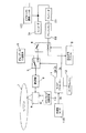
本実施形態のデジタルビデオレコーダは、光ディスク1および固定記憶デバイス5に対してデジタルデータを記録することができるデジタルビデオレコーダである。光ディスク1は、可交換型であり、このデジタルビデオレコーダから取り外され、他の光ディスク1に交換され得る。一方、固定記憶デバイス5は、このデジタルビデオレコーダに固定されている。
The digital video recorder of the present embodiment is a digital video recorder that can record digital data on the
図1においては、光ディスク1への記録動作に用いられる構成要素が複数のブロックに分けて記載されているが、固定記憶デバイス5への記録動作に用いられる構成要素は、「固定記憶デバイス5」のラベルが付された1つのブロックとして簡略的に記載されている。したがって、このブロックは、「記録媒体」だけではなく、書き込み/読み出しの必要な機構や回路を備えた駆動部を示している。固定記憶デバイス5の構成および動作は、公知の構成および動作であるため、その詳細な説明は割愛する。
In FIG. 1, the components used for the recording operation on the
本実施形態のデジタルビデオレコーダは、デジタルビデオレコーダの光ディスク用駆動部(光ディスクドライブ)にロードされた光ディスク1に対してレーザ光を照射する光ヘッド9を備えている。光ヘッド9を含む光ディスク用駆動部の構成自体は、公知の構成と同様である。
The digital video recorder according to the present embodiment includes an optical head 9 that irradiates a laser beam to the
光ヘッド9は、レーザ光を出力する光源として機能する半導体レーザと、このレーザ光を光ディスク上に集光し、光ディスク上にビームスポットを形成する対物レンズと、対物レンズを駆動するアクチュエータと、光ディスク1で反射されたレーザ光を受け取り電気信号に変換する受光部などを構成要素として備えている。
The optical head 9 includes a semiconductor laser that functions as a light source that outputs laser light, an objective lens that focuses the laser light on the optical disk to form a beam spot on the optical disk, an actuator that drives the objective lens, and an optical disk. A light receiving unit that receives the laser light reflected by the
図1に示す例では、光ヘッド9から出力される再生信号RFおよびトラッキングエラー信号TEが、それぞれ、異常状態検出回路10およびトラッキング制御回路13に送られる。トラッキング制御回路13は、レーザ光の結像点を精度良く所望のトラック上に位置させるように光ヘッド9の動作を制御する。異常状態検出回路10は、光ディスク1へのデータ記録中に異常が発生したことを検知することができる。
In the example shown in FIG. 1, the reproduction signal RF and the tracking error signal TE output from the optical head 9 are sent to the abnormal
光ヘッド9から出力された電気信号を受け取り、その電気信号を処理する信号処理回路は、DSPなどのLSIによって機能的に実現され得る。このようなLSIを使用する場合、異常検出回路10やトラッキング制御回路13は、個別のアナログ回路として構成されるのではなく、デジタル信号処理のソフトウェアの機能ブロックとして実現されることになる。
A signal processing circuit that receives the electric signal output from the optical head 9 and processes the electric signal can be functionally realized by an LSI such as a DSP. When such an LSI is used, the
本実施形態のデジタルビデオレコーダは、TVチューナ2が受信した放送データを受け取り、この放送データを例えばMPEG2ストリームへ符号化するエンコーダ31を備えている。エンコーダ31によって符号化されたデータ(データストリーム)は、光ディスク1または固定記憶デバイス5に選択的に蓄積される。
The digital video recorder of the present embodiment includes an
本実施形態では、TVチューナによってアナログ放送電波を受信するが、本発明に使用可能なTVチューナは、これに限定されず、デジタル放送電波を受信するものであってもよい。TVチューナ2がデジタル放送を受信し、MPEG2ストリームなどの符号化されたデータ(データストリーム)を出力できる場合は、図1に示すエンコーダ31を省略しても良い。なお、TVチューナ2は、デジタルビデオレコーダの外部に存在しても良いし、デジタルビデオレコーダに内蔵されていても良い。
In the present embodiment, the analog broadcast wave is received by the TV tuner. However, the TV tuner that can be used in the present invention is not limited to this, and the TV tuner that receives the digital broadcast wave may be used. If the
このデジタルビデオレコーダにより、放送番組を直接的に光ディスク1へ記録する場合、上記のデータストリームは、セレクタ4、7を通って変調器8に送られる。変調器8は、受け取ったデータストリームを記録メディアに適した記録信号(例えば(1,7)PWM信号)に変換する。
When a broadcast program is directly recorded on the
セレクタ4、7の動作は、マイクロプロセッサ11によって制御される。マイクロプロセッサ11が実行するプログラムは、プログラムメモリ12に格納されている。変調器8から出力されたデータは、光ヘッド9を介して光ディスク1に書き込まれる。
The operations of the selectors 4 and 7 are controlled by the
光ディスク1に対するデータの記録中に異常が検知されたとき、マイクロプロセッサ11は、光ディスク1へのデータの転送を中止し、前記固定記憶デバイス5へデータを転送するように動作する。
When an abnormality is detected while data is being recorded on the
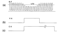
以下、図2(a)から(c)を参照して、データ記録中の異常検出方法の一例を説明する。 Hereinafter, an example of an abnormality detection method during data recording will be described with reference to FIGS.
図2(a)は、光ヘッド9から出力されるトラッキングエラー信号TEの波形を示している。トラッキングエラー信号TEは、光ディスクにおける情報トラックの中心とレーザ光のビームスポットとの間に生じた位置ずれを示す信号である。このような位置ずれが生じていないとき、トラッキングエラー信号TEは電位VREFに略等しくなる。 FIG. 2A shows a waveform of the tracking error signal TE output from the optical head 9. The tracking error signal TE is a signal indicating a positional shift generated between the center of the information track on the optical disc and the beam spot of the laser light. When such a displacement does not occur, the tracking error signal TE becomes substantially equal to the potential VREF.
トラッキング制御回路13は、トラッキングエラー信号TEに基づいてビームスポットの位置決め制御を実行する。より具体的には、トラッキングエラー信号TEのレベルが電位VREFに常に等しくなるように光ヘッド9内のアクチュエータを駆動する。その結果、光ディスク上におけるビームスポットは、光ディスク1が高速で回転している間、所望の情報トラックの中心を追従することができる。
The
光ディスクへのデータを書き込んでいるとき、または光ディスクからデータを読み出しているとき、何らかの原因によって「トラッキング外れ」が発生すると、トラッキング制御が不能の状態に陥る。トラッキング外れが発生すると、トラッキング信号TEのレベルが、図2(a)に示される上限値VTH+を超えるか、または下限値VTH−を下回ることになる。異常状態検出回路10は、トラッキングエラー信号TEのレベルと、上限値VTH+および下限値VTH−とを比較し、トラッキングエラー信号TEのレベルが上限値VTH+および下限値VTH−で規定される範囲から外れたとき、図2(b)に示す異常検出信号VAをマイクロプロセッサ11に送出する。異常検出信号VAは、トラッキングはずれが生じていないとき、「Low」のレベルにあり、トラッキングエラー信号TEのレベルが上限値VTH+および下限値VTH−で規定される範囲から外れると、「Low」から「High」へ状態を遷移させる。
When data is written to the optical disk or data is read from the optical disk, if "out of tracking" occurs for some reason, tracking control is disabled. When the tracking error occurs, the level of the tracking signal TE exceeds the upper limit value VTH + shown in FIG. 2A or falls below the lower limit value VTH−. The abnormal
マイクロプロセッサ11は、異常検出信号VAに応答して、図2(c)に示す転送切り替え信号CAを生成する。転送切り替え信号CAの始期(「Low」から「High」への立ち上がりのタイミング)は、異常検出信号VAの立ち上がりで決定されるが、終期はマイクロプロセッサ11が決定する。転送切り替え信号CAの送出は、例えば、ある単位時間内に一度も異常検出信号VAが発生しなくなったことが確認された時に停止するようにしてもよいし、異常検出信号VAの立ち上がりから予め設定された時間(例えば10秒)経過後に一律に停止するようにしてもよい。あるいは、固定記憶デバイス5の空き容量が充分にある場合は、放送番組が終了するまで、転送切り替え信号CAを送出し続けても良い。
The
次に、図3(a)から(c)を参照して、データ記録中の異常検出方法の他の例を説明する。 Next, another example of a method for detecting an abnormality during data recording will be described with reference to FIGS.
図3(a)は、光ディスク1からの反射光から得られる再生信号(RF)の波形を示している。フォーカス方向の外乱などによってフォーカス位置の制御が不能になった場合、図3(a)に示すように再生信号(RF)の上側のエンベロープが小さくなる。光ディスク1に対する書き込みの異常は、この再生信号(RF)の上側エンベロープの落ち込みから検出することも可能である。予め設定されたレベルよりも再生信号(RF)の上側エンベロープが低くなったとき、異常状態検出回路10が図3(b)に示す異常検出信号VAをマイクロプロセッサ11に送出する。この異常検出信号VAに応答して、図3(c)に示す転送切り替え信号CAが送出される。具体的には、転送切り替え信号CAのレベルが「Low」から「High」に遷移すると、セレクタ4によって伝送経路が切り替えられる。すなわち、エンコーダ31から光ディスク1へ情報転送する経路は閉じられ、代わって固定記憶デバイス5への経路が開かれる。
FIG. 3A shows a waveform of a reproduction signal (RF) obtained from light reflected from the
本実施形態では、図1に示すエンコーダ31から出力されるデータを所定時間遅延させるためのバッファメモリ32が設けられている。このため、転送切り替え信号CAのレベルが「High」のとき、このバッファメモリ32から出力されたデータがセレクタ4を通して固定記憶デバイス5に送られる。
In the present embodiment, a
異常状態検出回路10が作動したときには、既にデータの書き込みに失敗している可能性が高い。言い換えれば、バッファメモリ32が無いと、転送切り替え信号CAに応答してエンコーダ31の出力を固定記憶デバイス5への書き込みを開始したのでは、既に記録すべき情報の一部が欠損している場合がある。そこで、本実施形態では、固定記憶デバイス5には、バッファメモリ32に一時蓄積されている上記欠損データと同一データを転送し、情報の欠損防止を図っている。
When the abnormal
本実施形態のデジタルビデオレコーダでは、プログラムメモリ12に格納されたマイクロプロセッサ11のプログラムによって上記の各処理が実行される。これらの処理の結果、TVチューナ2によって受信されたデータは、転送切り替え信号CAに応じて、光ディスク1および固定記憶デバイス5のうちの選択された記録媒体に送られ、記録される。
In the digital video recorder of the present embodiment, each of the above processes is executed by the program of the
図4は、異常検出信号VAおよび転送切り替え信号CAの波形と、記憶媒体の切り替えとの関係を示す模式図である。 FIG. 4 is a schematic diagram showing the relationship between the waveforms of the abnormality detection signal VA and the transfer switching signal CA and the switching of the storage medium.
光ディスク1に対する放送番組の記録開始により、論理アドレス#1に対応するデータが光ディスク1上に記録され始める。論理アドレス#1から論理アドレス#Nまでが割り当てられたデータが光ディスク1上に記録された後、論理アドレス#N+1のデータを記録している途中で書き込み異常が検出されたとする。この場合、論理アドレス#N+1以降のデータが固定記憶デバイス5に記録される。
When recording of a broadcast program on the
固定記憶デバイス5に送られるデータ(論理アドレス#N+1以降のデータ)には、光ディスク1に蓄積されている情報の少なくとも一部に対して一義的に関連付けられる識別情報が付加される。この識別情報によれば、固定記憶デバイス5に記録されているデータが、本来、光ディスク1のどの位置に記録されるべきものであったかが特定される。このような識別情報が付加されていると、複数回の異常が検知され、その都度、固定記憶デバイス5にデータが退避・記録された場合でも、固定記憶デバイス5からデータを適切に再生することができるようになる。
To the data (data after logical address # N + 1) sent to the fixed
識別情報は、例えば、光ディスク1へ記録される情報に附されている論理アドレス(#1〜#N)と連続性のある論理アドレス(#N+1〜)を含むことができる。固定記憶デバイス5が、他の用途(例えば、通常の番組記録)にも用いられている場合には、光ディスクへの書き込み異常時に固定記憶デバイス5に書き込まれたデータ(待避データファイル)であることを識別できるようにすることが好ましい。このため、ファイルの種別表示のための管理情報を含んだヘッダを付加しておくことが好ましい。上記アドレスおよびヘッダは、エンコーダ31によって附される。
The identification information can include, for example, logical addresses (# N + 1 to # N + 1) that are continuous with the logical addresses (# 1 to #N) attached to the information recorded on the
本実施形態では、転送切り替え信号CAのレベルがHighのとき、すなわち記録異常時においては、図4に示すようにダミーデータが光ディスク1上に記録される。ダミーデータは、例えば乱数データであり、図1に示すダミーデータ生成回路6から出力される。ダミーデータ生成回路6から出力されるダミーデータは、図1のセレクタ7により、光ディスク1に供給され、そこに記録される。
In this embodiment, when the level of the transfer switching signal CA is High, that is, when recording is abnormal, dummy data is recorded on the
本発明の主たる目的は、前述のように、光ディスクの傷や振動外乱によって発生するトラック飛びなどによって放送番組の途中で記録データが欠損することを防止することにある。このため、光ディスクそのものには問題が無いか、問題があったとしても軽微である場合が多い。そのような場合、固定記憶デバイス5にデータを記録している途中において光ディスク1にまったくデータを記録しないと、未記録トラックが形成されるため、いわゆる虫食い状態が発生する。
A main object of the present invention is to prevent loss of recorded data in the middle of a broadcast program due to a scratch on an optical disc or a skipped track caused by vibration disturbance as described above. For this reason, there are many cases where the optical disc itself has no problem, or even if there is a problem, the problem is slight. In such a case, if no data is recorded on the
相変化材料から記録層が形成されている光ディスクの場合は、記録トラックと未記録トラックとの間で反射率差が小さいが、色素系の材料から記録層が形成された追記型ディスクの場合は、反射率差が大きい。また、一方の層を透過させて他方の層に対してデータの記録・再生を行う、いわゆる2層型光ディスクでは、未記録領域が虫食い状態で存在すると、サーボの不安定動作が生じやすく、他層へ記録する際のレーザーパワー変動を招来することがある。このような問題を解決するため、本実施形態では、転送切り替え信号CAのレベルがHighのときであっても、光ディスクにデータを記録することが可能な状態(異常検出信号VAがLow状態)であれば、ダミーデータを光ディスクに記録する(図4参照)。 In the case of an optical disc having a recording layer formed from a phase change material, the difference in reflectance between a recorded track and an unrecorded track is small, but in the case of a write-once disc having a recording layer formed from a dye-based material, And the reflectance difference is large. Also, in a so-called two-layer type optical disc that transmits and records data to and from one layer while transmitting the other layer, if an unrecorded area exists in a worm-like state, servo unstable operation is likely to occur. This may cause laser power fluctuation when recording on the layer. In order to solve such a problem, in the present embodiment, even when the level of the transfer switching signal CA is High, the data can be recorded on the optical disk (the abnormality detection signal VA is in the Low state). If so, the dummy data is recorded on the optical disk (see FIG. 4).
このように本実施形態によれば、光ディスクの傷や外乱振動などによるトラック飛びが発生して、放送番組の光ディスク1への記録に重大な支障を来す場合であっても、固定記憶デバイス5を補助的に用いることにより、データを欠損させることなく、番組内容の全部を収録することができる。
As described above, according to the present embodiment, even if a track jump occurs due to a scratch on the optical disk, disturbance vibration, or the like, which seriously hinders the recording of the broadcast program on the
本実施形態では、光ディスク1に対する記録時に異常が生じたとき、データ記録の対象となる記録媒体を光ディスク(第1記録媒体)から固定記憶デバイス(第2記録媒体)に切り替えることにより、「第2記録媒体」にデータを退避・記録しているが、本発明における第2記録媒体は、固定型に限定されず、可交換型であってもよい。例えば、PCMCIAスロットルに挿入されたカード型のハードディスク装置や半導体メモリ(メモリカード)であってもよい。
In the present embodiment, when an abnormality occurs during recording on the
(実施形態2)
次に、図5を参照しながら、本発明によるデジタルビデオレコーダの第2の実施形態について説明する。
(Embodiment 2)
Next, a second embodiment of the digital video recorder according to the present invention will be described with reference to FIG.
本実施形態のデジタルビデオレコーダが、実施形態1のデジタルビデオレコーダと異なる点は、TVチューナ2とバッファメモリ32との間にエンコーダ33を備えていることと、固定記憶デバイス5として半導体メモリを備えている点にある。
The digital video recorder according to the present embodiment differs from the digital video recorder according to the first embodiment in that an
半導体メモリのビット単価は、ハードディスクに比べて高いため、ハードディスクの容量と同程度の大きな容量を持つ半導体メモリを搭載することは、デジタルビデオレコーダの価格を高め、好ましくない。記録容量が相対的に小さな半導体メモリ、例えば64MBのSRAMを固定記憶デバイス5として用いる場合、MPEG2の標準的な(SD)画像であれば1分30秒程度しか固定記憶デバイス5に記録できない。このような場合、光ディスクへのデータ記録中に異常が生じ、この異常からの回復が1分30秒以上続いたならば、固定記憶デバイス5に記録すべきデータが固定記憶デバイス5の容量を超えてしまうことになり、情報の欠損が生じてしまう。
Since the cost per bit of a semiconductor memory is higher than that of a hard disk, it is not preferable to mount a semiconductor memory having a capacity as large as the capacity of a hard disk because the price of a digital video recorder increases. When a semiconductor memory having a relatively small recording capacity, for example, a 64 MB SRAM is used as the fixed
上記の問題を解決するため、本実施形態では、図5に示すように固定記憶デバイス5に書き込むデータをエンコーダ33によって符号化し、情報量を低減している。このため、固定記憶デバイス5として、比較的容量の小さな半導体メモリを用いることができる。
In order to solve the above problem, in the present embodiment, as shown in FIG. 5, data to be written to the fixed
より具体的には、TVチューナによって受信される情報が動画像・音声データである場合、エンコーダ33が転送レートの相対的に低い画像・音声ストリームを生成する。エンコーダ33の働きによりも、画像・音声の質は或る程度犠牲になるが、より長い時間の動画像。音声データを固定記憶デバイス5に記録することが可能になり、上述した情報の欠損を回避しやすくなる。転送レートを低下するには、例えば画素数または1秒あたりの動画枚数を減らすことによって達成することができる。
More specifically, when the information received by the TV tuner is video / audio data, the
(実施形態3)
次に、図6を参照しながら、本発明によるデジタルビデオレコーダの第3の実施形態を説明する。
(Embodiment 3)
Next, a third embodiment of the digital video recorder according to the present invention will be described with reference to FIG.
本実施形態のデジタルビデオレコーダは、光ディスク1に記録されているデータを再生するために必要な復調器108およびデコーダ131を備えている。復調器108は、光ディスク1で反射されたレーザ光を受けた光ヘッド9内の受光部は、レーザ光の強度に従った再生信号RFを生成するとともに、光ディスク1上におけるレーザ光のビームスポット位置を示すアドレス情報も生成される。
The digital video recorder of the present embodiment includes a
図6には記載されていないが、本実施形態のデジタルビデオレコーダも、実施形態1、2のデジタルビデオレコーダと同様に、エンコーダ31や変調器8を備えている。
Although not shown in FIG. 6, the digital video recorder of the present embodiment also includes an
本実施形態のデジタルビデオレコーダは、再生動作の開始時に固定記憶デバイス5にアクセスし、固定記憶デバイス5に記録されているファイルのヘッダを読み出す。デジタルビデオレコーダは、このファイルのヘッダの内容に基づき、光ディスク1に書き込み異常が発生していたことを知ることができる。
The digital video recorder of the present embodiment accesses the fixed
本実施形態のデジタルビデオレコーダは、固定記憶デバイス5に格納されているファイルの先頭の論理アドレス(#N+1)から、光ディスク1における情報欠損位置を特定することができる。したがって、光ディスク1に記録されている情報を読み出すとき、論理アドレス#N+1からは後は固定記憶デバイス5にアクセスし、固定記憶デバイス5に記録されているデータを再生する。
The digital video recorder according to the present embodiment can identify the information loss position on the
以下、光ディスク1および固定記憶デバイス5に分散記録されたデータを本実施形態のデジタルビデオレコーダによって再生する動作を、より詳細に説明する。
Hereinafter, the operation of reproducing the data distributedly recorded on the
本実施形態のデジタルビデオレコーダにおけるマイクロプロセッサ11は、復調器108によって得られたアドレス情報を常にモニターしている。固定記憶デバイス5から上記のヘッダ情報を受け取ったマイクロプロセッサ11は、復調器108によって得られるアドレスが#Nになったとき、光ディスク1からのデータ再生を一旦停止する。データ再生の停止は、例えば、マイクロプロセッサ11からトラッキング制御回路13に対してトラッキングホールド指令信号(THD)を送信し、アドレス#N以降のデータ領域のトラッキングを禁止することによって行なうことができる。
The
光ディスク1からのデータ再生を停止するとともに、マイクロプロセッサ11は切り替え信号CAを発してセレクタ104を切り替える。これにより、光ディスク1から再生・復調された信号(DOD)の経路を切断し、固定記憶デバイス5からの信号(DHD)をデコーダ131に供給する。
While stopping the data reproduction from the
信号DHDは、アドレス#N+1から始まるファイル情報を含んでいる。従って、デコーダ131は情報の供給源の如何に係わらず、順次、アドレスの連続した情報を得ることができ、その結果、シームレスにビデオ情報の再生を実行することができる。
The signal DHD includes file information starting from the address # N + 1. Therefore, the
固定記憶デバイス5に格納されるファイルの上記ヘッダには、書き込み異常が発生した光ディスク1のボリュームラベルなどを書き込んでおくことが好ましい。ホリームラベルから、書き込み異常の生じた光ディスクを特定することができる。このため、ユーザが複数の光ディスクから任意に選択した光ディスクをデジタルビデオレコーダにロードし、データ再生を行なう場合においても、固定記憶デバイス5に記録されているデータを必要に応じて適切に読み出すことが可能になる。
It is preferable that a volume label or the like of the
固定記憶デバイス5からデータを読み出した後、再度、光ディスク1からのデータを再生する場合を説明する。この場合、マイクロプロセッサ11は、図4に示すダミーデータが記録されている領域の直後の領域に、ヘッドのトラッキング位置を移動させるようにトラックジャンプ指令TJMPをトラッキング制御回路13に送出する。
A case in which data is read from the fixed
なお、再合成された情報は、完全修復ファイルとして光ディスク1または固定記憶デバイス5に再度記録されてもよい。完全修復ファイルが記録される光ディスクは、記録異常が発生した光ディスクではなく、他の光ディスクであってもよい。図6の波線で示されているように、セレクタ104から出力されるシームレスな修復データを一旦バッファメモリ132に記録し、その後、固定記憶デバイス5に記録するようにすれば、固定記録デバイス5には、完全な形でファイルが残ることになる。光ディスク1に空き容量があれば、図6において不図示の変調器(図1における変調器8)を通してバッファメモリ132の出力を光ディスク1に書き込んでもよい。
The re-synthesized information may be recorded again on the
(実施形態4)
次に、図7を参照しながら、本発明によるデジタルビデオレコーダの第4の実施形態を説明する。本明細書においては、「デジタルビデオレコーダ」の用語は、動画・音声のデジタルデータを記録することができる装置を広くカバーしており、ビデオカメラを含むものとする。
(Embodiment 4)
Next, a fourth embodiment of a digital video recorder according to the present invention will be described with reference to FIG. In this specification, the term “digital video recorder” widely covers a device capable of recording moving image and audio digital data, and includes a video camera.
本実施形態の構成が、図5に示すデジタルビデオレコーダの構成と異なる点は、ビデオ信号の供給源がビデオカメラ撮像ユニット120と、光ディスク1への書き込みの異常を検知するために使用される加速度センサ100とを備えている点である。
The configuration of the present embodiment is different from the configuration of the digital video recorder shown in FIG. 5 in that the video signal source is a video
ビデオカメラ撮像ユニット120は、公知の構成を備えていればよく、例えばカメラ光学系およびCCD撮像素子を内部に有している。撮影中に、ビデオカメラ撮像ユニット120から供給される信号は、TV放送の場合と同様、非インタラクティブ的である。したがって、蓄積(スレーブ)側の事情による中断が認められない性質を有している。
The video
本実施形態によれば、撮像データを光ディスク1への記録している最中に発生した異常を検出することができる。異常が検知されたときは、固定記憶デバイス5にデータを待避することにより、情報を欠損させることなく、ビデオ撮影データを記録することが可能となる。
According to the present embodiment, it is possible to detect an abnormality that has occurred while recording image data on the
持ち運ばれることの多いビデオカメラの場合、光ヘッドのトラッキングが外れる主原因は、カメラそのものに作用する振動および衝撃であると考えられる。このため、本実施形態では、加速度センサ100を用いて書き込み時の異常を検知するようにしている。
In the case of a video camera that is often carried, it is considered that the main cause of the tracking loss of the optical head is vibration and impact acting on the camera itself. For this reason, in this embodiment, an abnormality at the time of writing is detected using the
加速度センサ100は、微小振り子の運動を計測する方式、またはピエゾ素子が振動する際に発生する起電力を検出する方式で動作する一般的なセンサであってもよい。あるいは、光ヘッド9によって検出されるフォーカスエラー信号またはトラッキングエラー信号の変化を検出して、異常な加速度を検出する構成を有していても良い。
The
加速度センサ100によって検出された加速度に基づく異常検出信号VAが所定のしきい値を超えたことがマイクロプロセッサ11によって判断されたとき、マイクロプロセッサ11は、ビデオカメラ撮像ユニット120を情報源とする信号の経路を光ディスク1側から固定記憶デバイス5側へ切り替える。これにより、データの待避処理を実行するため、振動・衝撃下においても、撮像データを欠損させることなく、記録媒体に記録することができる。
When the
本発明は、放送番組を光ディスクなどに記録するデジタルビデオレコーダや、動画や音声を光ディスクなどに記録するカムコーダなどを含むデジタルビデオレコーダに適用される。 INDUSTRIAL APPLICABILITY The present invention is applied to a digital video recorder including a digital video recorder for recording a broadcast program on an optical disk or the like, and a camcorder for recording moving images or audio on an optical disk or the like.
1 光ディスク
2 TVチューナ
4、7 セレクタ
5 固定記憶デバイス
6 ダミーデータ生成回路
8 変調器
9 光ヘッド
10 異常状態検出回路
11 マイクロプロセッサ
12 プログラムメモリ
13 トラッキング制御回路
31 エンコーダ
32 バッファメモリ
108 復調器
120 ビデオカメラ撮像ユニット
131 デコーダ
132 バッファメモリ
DESCRIPTION OF
Claims (19)
前記第1記録媒体にデータを記録している途中で異常が発生したとき、前記異常を検知する異常状態検出手段と、
を備え、
前記第1記録媒体に前記データを記録している途中において、前記異常状態検出手段が前記異常を検知したとき、前記第1記録媒体への前記データの記録を停止し、前記第1記録媒体に記録すべきデータを前記第2記憶媒体に記録する、デジタルビデオレコーダ。 A digital video recorder capable of recording data on a recording medium selected from a first recording medium and a second recording medium,
An abnormal state detecting means for detecting the abnormality when an abnormality occurs while data is being recorded on the first recording medium;
With
While the data is being recorded on the first recording medium, when the abnormal state detecting means detects the abnormality, the recording of the data on the first recording medium is stopped, and the recording is performed on the first recording medium. A digital video recorder for recording data to be recorded on the second storage medium.
前記第2記録媒体はハードディスクまたは半導体メモリである請求項1から5のいずれかに記載のデジタルビデオレコーダ。 The first recording medium is an optical disc;
6. The digital video recorder according to claim 1, wherein said second recording medium is a hard disk or a semiconductor memory.
前記第2記録媒体はハードディスクまたは半導体メモリである請求項4または5に記載のデジタルビデオレコーダ。 The first recording medium and the other recording medium are optical disks;
The digital video recorder according to claim 4, wherein the second recording medium is a hard disk or a semiconductor memory.
前記第2記録媒体は、固定型である請求項1から9のいずれかに記載のデジタルビデオレコーダ。 The first recording medium is exchangeable,
The digital video recorder according to claim 1, wherein the second recording medium is a fixed type.
前記第1記憶媒体に記録されるデータが、前記撮像素子から出力されたデータである請求項1から10のいずれかに記載のデジタルビデオレコーダ。 It has an image sensor,
The digital video recorder according to claim 1, wherein the data recorded on the first storage medium is data output from the image sensor.
前記第1記録媒体に前記データを記録している途中において、異常を検知するステップと、
前記異常を検知したとき、前記第1記録媒体への前記データの記録を停止し、前記第1記録媒体に記録すべきデータを前記第2記憶媒体に記録するステップと、
を含む方法。 A method of driving a digital video recorder capable of recording data on a recording medium selected from a first recording medium and a second recording medium,
Detecting an abnormality during the recording of the data on the first recording medium;
Stopping the recording of the data on the first recording medium when the abnormality is detected, and recording data to be recorded on the first recording medium on the second storage medium;
A method that includes
前記マイクロプロセッサに対して、
前記第1記録媒体に前記データを記録している途中において、異常を検知するステップと、
前記異常を検知したとき、前記第1記録媒体への前記データの記録を停止し、前記第1記録媒体に記録すべきデータを前記第2記憶媒体に記録するステップと、
を実行させるプログラム。 A program incorporated in a microprocessor of a digital video recorder capable of recording data on a recording medium selected from a first recording medium and a second recording medium,
For the microprocessor,
Detecting an abnormality during the recording of the data on the first recording medium;
Stopping the recording of the data on the first recording medium when the abnormality is detected, and recording data to be recorded on the first recording medium on the second storage medium;
A program that executes
Priority Applications (1)
| Application Number | Priority Date | Filing Date | Title |
|---|---|---|---|
| JP2004002618A JP2004241104A (en) | 2003-01-15 | 2004-01-08 | Digital video recorder, its driving method, and program |
Applications Claiming Priority (2)
| Application Number | Priority Date | Filing Date | Title |
|---|---|---|---|
| JP2003007181 | 2003-01-15 | ||
| JP2004002618A JP2004241104A (en) | 2003-01-15 | 2004-01-08 | Digital video recorder, its driving method, and program |
Publications (2)
| Publication Number | Publication Date |
|---|---|
| JP2004241104A true JP2004241104A (en) | 2004-08-26 |
| JP2004241104A5 JP2004241104A5 (en) | 2007-02-15 |
Family
ID=32964757
Family Applications (1)
| Application Number | Title | Priority Date | Filing Date |
|---|---|---|---|
| JP2004002618A Pending JP2004241104A (en) | 2003-01-15 | 2004-01-08 | Digital video recorder, its driving method, and program |
Country Status (1)
| Country | Link |
|---|---|
| JP (1) | JP2004241104A (en) |
Cited By (5)
| Publication number | Priority date | Publication date | Assignee | Title |
|---|---|---|---|---|
| JP2006338825A (en) * | 2005-06-03 | 2006-12-14 | Plannet Associate Co Ltd | Apparatus for recording digital audio and video information |
| JP2008035131A (en) * | 2006-07-27 | 2008-02-14 | Canon Inc | Recording apparatus and its control method |
| JP2009134829A (en) * | 2007-11-30 | 2009-06-18 | Toshiba Corp | Device and method for recording information |
| JP2012226487A (en) * | 2011-04-18 | 2012-11-15 | Mitsubishi Electric Corp | Video monitoring recorder and video monitoring system |
| US8520478B2 (en) | 2005-06-29 | 2013-08-27 | Sony Corporation | Readout device, readout method, program, and program recording medium |
-
2004
- 2004-01-08 JP JP2004002618A patent/JP2004241104A/en active Pending
Cited By (6)
| Publication number | Priority date | Publication date | Assignee | Title |
|---|---|---|---|---|
| JP2006338825A (en) * | 2005-06-03 | 2006-12-14 | Plannet Associate Co Ltd | Apparatus for recording digital audio and video information |
| JP4533249B2 (en) * | 2005-06-03 | 2010-09-01 | 株式会社プランネット・アソシエイツ | Digital audio / video information recording device |
| US8520478B2 (en) | 2005-06-29 | 2013-08-27 | Sony Corporation | Readout device, readout method, program, and program recording medium |
| JP2008035131A (en) * | 2006-07-27 | 2008-02-14 | Canon Inc | Recording apparatus and its control method |
| JP2009134829A (en) * | 2007-11-30 | 2009-06-18 | Toshiba Corp | Device and method for recording information |
| JP2012226487A (en) * | 2011-04-18 | 2012-11-15 | Mitsubishi Electric Corp | Video monitoring recorder and video monitoring system |
Similar Documents
| Publication | Publication Date | Title |
|---|---|---|
| US7437053B2 (en) | Digital video recorder, method of driving the video recorder and program | |
| RU2006122356A (en) | INFORMATION PLAYBACK SYSTEM USING THE INFORMATION MEMORY MEDIA | |
| US7620299B2 (en) | Data recording device for recording data in basic recording units | |
| JP3915503B2 (en) | Information recording apparatus and information recording method | |
| JP2004241104A (en) | Digital video recorder, its driving method, and program | |
| US7336888B2 (en) | Method and apparatus for performing continuous capture during recording real-time data | |
| JP3173634B2 (en) | Disk recording method and apparatus | |
| JP2006196071A (en) | Information recording device | |
| JP4434006B2 (en) | Information recording / reproducing device | |
| JP2004241104A5 (en) | ||
| WO2007123275A1 (en) | Optical disk recording apparatus and method for controlling optical disk recording | |
| JP4280702B2 (en) | Recording apparatus and control method thereof | |
| US20090162034A1 (en) | Information recording/reproducing apparatus and method for recording/reproducing information | |
| US20070268802A1 (en) | Optical disc recording and reproducing apparatus | |
| JP2005302225A (en) | Optical disk recorder | |
| JP3629138B2 (en) | Disk unit | |
| US7573796B2 (en) | Information recording apparatus | |
| CN1851816B (en) | Information processing apparatus and method | |
| JP2008159163A (en) | Disk recording/reproducing system | |
| JP2005302226A (en) | Optical disk recorder | |
| KR20090051815A (en) | Method for safely recording data on storage in hdd-dvd system | |
| JP2006079755A (en) | Recorder | |
| JP2005332469A (en) | Disk unit | |
| JP2002093067A (en) | Disk device | |
| JP2003157624A (en) | Disk unit |
Legal Events
| Date | Code | Title | Description |
|---|---|---|---|
| A521 | Written amendment |
Free format text: JAPANESE INTERMEDIATE CODE: A523 Effective date: 20061221 |
|
| A621 | Written request for application examination |
Free format text: JAPANESE INTERMEDIATE CODE: A621 Effective date: 20061221 |
|
| A977 | Report on retrieval |
Free format text: JAPANESE INTERMEDIATE CODE: A971007 Effective date: 20080514 |
|
| A131 | Notification of reasons for refusal |
Free format text: JAPANESE INTERMEDIATE CODE: A131 Effective date: 20080527 |
|
| A02 | Decision of refusal |
Free format text: JAPANESE INTERMEDIATE CODE: A02 Effective date: 20080930 |