JP4743855B2 - Data storage device and control method thereof - Google Patents
Data storage device and control method thereof Download PDFInfo
- Publication number
- JP4743855B2 JP4743855B2 JP2005254817A JP2005254817A JP4743855B2 JP 4743855 B2 JP4743855 B2 JP 4743855B2 JP 2005254817 A JP2005254817 A JP 2005254817A JP 2005254817 A JP2005254817 A JP 2005254817A JP 4743855 B2 JP4743855 B2 JP 4743855B2
- Authority
- JP
- Japan
- Prior art keywords
- heater
- data
- seek
- head
- mode
- Prior art date
- Legal status (The legal status is an assumption and is not a legal conclusion. Google has not performed a legal analysis and makes no representation as to the accuracy of the status listed.)
- Expired - Fee Related
Links
Images


Classifications
-
- G—PHYSICS
- G11—INFORMATION STORAGE
- G11B—INFORMATION STORAGE BASED ON RELATIVE MOVEMENT BETWEEN RECORD CARRIER AND TRANSDUCER
- G11B5/00—Recording by magnetisation or demagnetisation of a record carrier; Reproducing by magnetic means; Record carriers therefor
- G11B5/127—Structure or manufacture of heads, e.g. inductive
- G11B5/31—Structure or manufacture of heads, e.g. inductive using thin films
- G11B5/3109—Details
- G11B5/313—Disposition of layers
- G11B5/3133—Disposition of layers including layers not usually being a part of the electromagnetic transducer structure and providing additional features, e.g. for improving heat radiation, reduction of power dissipation, adaptations for measurement or indication of gap depth or other properties of the structure
- G11B5/3136—Disposition of layers including layers not usually being a part of the electromagnetic transducer structure and providing additional features, e.g. for improving heat radiation, reduction of power dissipation, adaptations for measurement or indication of gap depth or other properties of the structure for reducing the pole-tip-protrusion at the head transducing surface, e.g. caused by thermal expansion of dissimilar materials
-
- G—PHYSICS
- G11—INFORMATION STORAGE
- G11B—INFORMATION STORAGE BASED ON RELATIVE MOVEMENT BETWEEN RECORD CARRIER AND TRANSDUCER
- G11B5/00—Recording by magnetisation or demagnetisation of a record carrier; Reproducing by magnetic means; Record carriers therefor
- G11B5/48—Disposition or mounting of heads or head supports relative to record carriers ; arrangements of heads, e.g. for scanning the record carrier to increase the relative speed
- G11B5/58—Disposition or mounting of heads or head supports relative to record carriers ; arrangements of heads, e.g. for scanning the record carrier to increase the relative speed with provision for moving the head for the purpose of maintaining alignment of the head relative to the record carrier during transducing operation, e.g. to compensate for surface irregularities of the latter or for track following
- G11B5/60—Fluid-dynamic spacing of heads from record-carriers
- G11B5/6005—Specially adapted for spacing from a rotating disc using a fluid cushion
- G11B5/6011—Control of flying height
- G11B5/6029—Measurement using values derived from the data signal read from the disk
-
- G—PHYSICS
- G11—INFORMATION STORAGE
- G11B—INFORMATION STORAGE BASED ON RELATIVE MOVEMENT BETWEEN RECORD CARRIER AND TRANSDUCER
- G11B5/00—Recording by magnetisation or demagnetisation of a record carrier; Reproducing by magnetic means; Record carriers therefor
- G11B5/48—Disposition or mounting of heads or head supports relative to record carriers ; arrangements of heads, e.g. for scanning the record carrier to increase the relative speed
- G11B5/58—Disposition or mounting of heads or head supports relative to record carriers ; arrangements of heads, e.g. for scanning the record carrier to increase the relative speed with provision for moving the head for the purpose of maintaining alignment of the head relative to the record carrier during transducing operation, e.g. to compensate for surface irregularities of the latter or for track following
- G11B5/60—Fluid-dynamic spacing of heads from record-carriers
- G11B5/6005—Specially adapted for spacing from a rotating disc using a fluid cushion
- G11B5/6011—Control of flying height
- G11B5/6064—Control of flying height using air pressure
Description
本発明はデータ記憶装置及びその制御方法に関し、特に、ヘッドとメディアとの間のクリアランスを調整するヒータをヘッドに備えるデータ記憶装置及びそのヒータの制御方法に関する。 The present invention relates to a data storage device and a control method therefor, and more particularly to a data storage device including a heater for adjusting a clearance between a head and a medium in the head and a control method for the heater.
データ記憶装置として、光ディスク、磁気テープあるいは半導体メモリなどの様々な態様のメディアを使用する装置が知られているが、その中で、ハードディスク・ドライブ(HDD)は、コンピュータの記憶装置として広く普及し、現在のコンピュータ・システムにおいて欠かすことができない記憶装置の一つとなっている。さらに、コンピュータにとどまらず、動画像記録再生装置、カーナビゲーション・システム、携帯電話、あるいはデジタル・カメラなどで使用されるリムーバブルメモリなど、HDDの用途は、その優れた特性により益々拡大している。 As data storage devices, devices using various forms of media such as optical disks, magnetic tapes, and semiconductor memories are known. Among them, hard disk drives (HDDs) are widely used as computer storage devices. It is one of the storage devices indispensable in the current computer system. Furthermore, the use of HDDs such as a removable memory used in a moving image recording / reproducing apparatus, a car navigation system, a mobile phone, a digital camera, etc. is expanding more and more due to its excellent characteristics.
HDDで使用される磁気ディスクは、同心円状に形成された複数のデータ・トラックを有しており、各データ・トラックはアドレス情報を有する複数のサーボ・データとユーザ・データを含む複数のデータ・セクタが記録されている。各サーボ・データの間には、複数のデータ・セクタが記録されている。揺動するアクチュエータに支持されたヘッド・スライダのヘッド素子部が、サーボ・データのアドレス情報に従って所望のデータ・セクタにアクセスすることによって、データ・セクタへのデータ書き込み及びデータ・セクタからのデータ読み出しを行うことができる。 The magnetic disk used in the HDD has a plurality of data tracks formed concentrically, and each data track has a plurality of data including a plurality of servo data having address information and user data. A sector is recorded. A plurality of data sectors are recorded between each servo data. The head element part of the head slider supported by the oscillating actuator accesses the desired data sector according to the servo data address information, thereby writing data to the data sector and reading data from the data sector. It can be performed.
磁気ディスクの記録密度を向上には、磁気ディスク上を浮上するヘッド素子部と磁気ディスクとの間のクリアランスを小さくすることが重要である。このため、このクリアランスを調整するいくつかの機構が提案されている。そのうちの一つは、ヘッド・スライダにヒータを備え、そのヒータでヘッド素子部を加熱することよってクリアランスを調整する(例えば、特許文献1を参照)。本明細書において、これをTFC(Thermal Flyheight Control)と呼ぶ。TFCは、ヒータに電流を供給して発熱させ、熱膨張によってヘッド素子部12を突出させる。これによって、磁気ディスクとヘッド素子部との間のクリアランスを小さくすることができる。
ヘッド素子部は、通常動作においても熱膨張によって突出しうる。通常動作におけるヘッド素子部の突出には2つのタイプがあり、一つは環境温度の上昇に伴うヘッド素子部の突出であり、他の一つはデータ書き込み時におけるライト素子の発熱によるヘッド素子部の突出である。ライト素子はコイルに電流を流すことによって磁界を生成し、磁気ディスクにデータを書き込むため、そのライト電流によってライト素子が発熱する。 The head element portion can protrude due to thermal expansion even in normal operation. There are two types of protrusions of the head element part in normal operation, one is the protrusion of the head element part as the environmental temperature rises, and the other is the head element part due to heat generation of the write element during data writing Is a protrusion. Since the write element generates a magnetic field by passing a current through the coil and writes data to the magnetic disk, the write element generates heat due to the write current.
HDDの設計においては、ヘッド素子部と磁気ディスクとの間の衝突を避けるため、上述の環境温度による突出や、ライト電流による突出を考慮してクリアランスを決定する。このため、例えば、高温環境において十分な読み出し特性を達成することができるが、低温環境において十分な読み出し特性を得ることができないことが起こりうる。また、ライト素子への電流供給からヘッド素子部の突出までに相応の時間がかかるため、最初のいくつかのデータ・セクタへの書き込みが十分に行われない場合がある。 In designing the HDD, in order to avoid a collision between the head element portion and the magnetic disk, the clearance is determined in consideration of the protrusion due to the environmental temperature and the protrusion due to the write current. For this reason, for example, sufficient read characteristics can be achieved in a high temperature environment, but sufficient read characteristics cannot be obtained in a low temperature environment. In addition, since it takes a considerable time from the current supply to the write element to the protrusion of the head element portion, the first several data sectors may not be sufficiently written.
TFCは、ヘッド素子部と磁気ディスクとの間のクリアランスを低減するほか、これら読み出し特性の低下や、データ書き込み初期のプア・オーバーライトの問題を解決する手段を与える。一方、TFCは通常状態よりもヘッド素子部を突出するため、磁気ディスクとヘッド素子部との衝突を引き起こしやすい。そのため、TFCにおいてはヒータに通電することによってヘッド素子部を突出させるタイミングの制御が非常に重要である。 TFC not only reduces the clearance between the head element portion and the magnetic disk, but also provides a means for solving these deteriorations in reading characteristics and poor / overwrite problems at the initial stage of data writing. On the other hand, since the TFC protrudes from the head element portion as compared with the normal state, it easily causes a collision between the magnetic disk and the head element portion. Therefore, in TFC, it is very important to control the timing at which the head element portion protrudes by energizing the heater.
データのリードもしくはライトにおいて、シーク前からヒータに通電する場合、ヘッド素子部がシーク前に突出し、シークにおいて大きく移動するヘッド素子部と磁気ディスクとの衝突の蓋然性が大きく増加する。さらに、ヒータ近辺が突出した場合、ABS (Air Bearing Surface)の特性が変化しシークしている間、設計どおりのFlyheightを保てない可能性がある。一方、磁気ディスクからのデータの読み出しもしくはデータの書き込み開始時もしくはその開始後にヒータをONとすると、初期のデータ・セクタにおいて十分なアクセス特性を得ることができない。そのため、最初のデータ・セクタにアクセスする前に、ヘッド素子部を突出させておくことが重要である。 In the data read or write, when the heater is energized before seeking, the head element portion protrudes before seeking, and the probability of collision between the head element portion and the magnetic disk that moves greatly during seeking greatly increases. In addition, if the vicinity of the heater protrudes, it may not be possible to maintain the Flyheight as designed while the characteristics of the ABS (Air Bearing Surface) change and seek. On the other hand, if the heater is turned on at the time of reading or writing data from the magnetic disk or after the start of writing, sufficient access characteristics cannot be obtained in the initial data sector. Therefore, it is important to protrude the head element portion before accessing the first data sector.
本発明は上述のような事情を背景としてなされたものであって、ヒータを使用してヘッドを突出させてメディアとのクリアランスを調整する技術において、ヘッドのデータ領域へのアクセス(読み出しもしくは書き込み)をより確実なものとすると共に、メディアとヘッドとの衝突の可能性を低減することを目的とするものである。 The present invention has been made in the background as described above. In a technique for adjusting a clearance with a medium by projecting a head using a heater, access (reading or writing) to a data area of the head is performed. It is an object of the present invention to make the image more reliable and reduce the possibility of collision between the media and the head.
本発明の第1の態様に係るデータ記憶装置は、回転するメディア上を浮上するスライダと、前記スライダに配置されたヘッド素子部と、前記ヘッド素子部をターゲット・トラックに向けてシークし、そのシークを異なる複数の制御モードにおいて実行するコントローラと、前記スライダに配置され、前記シークの最終モードに入ってから前記ヘッド素子部がデータ領域へアクセスする前にON状態となり、そのヘッド素子部のデータ領域アクセスまで連続ON状態であり、そのヘッド素子部を熱膨張によって突出させて前記メディアとの間のクリアランスを調整するヒータを備えるものである。ヒータをシークの最終モードに入ってからヘッド素子部がデータ領域へアクセスする前にON状態にすることによって、ヘッド素子部とメディアとの衝突の可能性と低減するとともに、ヘッド素子部がデータ領域にアクセスするタイミングで十分にヘッド素子部を突出させることができる。 A data storage device according to a first aspect of the present invention includes a slider that floats on a rotating medium, a head element unit disposed on the slider, and seeks the head element unit toward a target track. A controller that executes seek in a plurality of different control modes and the slider, and is turned on before the head element unit accesses the data area after entering the seek final mode. The heater is continuously ON until the area is accessed, and includes a heater that projects the head element portion by thermal expansion to adjust the clearance with the medium. By turning on the heater before the head element section accesses the data area after entering the seek final mode, the possibility of collision between the head element section and the media is reduced, and the head element section is placed in the data area. The head element portion can be sufficiently projected at the timing of accessing the head.
前記ヒータは、前記シークが前記最終モードに入ったことに応答してON状態となり、そのヘッド素子部のデータ領域アクセスまで連続ON状態であることが好ましい。これによって、ヘッド素子部を突出させる時間を確実に確保することができる。あるいは、前記ヒータは、前記ヘッド素子部がターゲット・トラックに到着したことに応答してON状態となり、そのヘッド素子部のデータ領域アクセスまで連続ON状態であることが好ましい。これによって、ヘッド素子部の衝突危険性の低減と熱膨張のための時間の確保を効果的にバランスすることができる。もしくは、前記ヒータは、前記シークの完了に応答してON状態となり、そのヘッド素子部のデータ領域アクセスまで連続ON状態であることが好ましい。これによって、ヘッド素子部とメディアとの衝突の可能性をより低くすることができる。 It is preferable that the heater is turned on in response to the seek entering the final mode, and is continuously turned on until the data area access of the head element unit. As a result, it is possible to ensure the time for the head element portion to protrude. Alternatively, it is preferable that the heater is turned on in response to the head element unit arriving at the target track, and is continuously on until the data area of the head element unit is accessed. As a result, it is possible to effectively balance the reduction of the risk of collision of the head element portion and the securing of time for thermal expansion. Alternatively, it is preferable that the heater is turned on in response to the completion of the seek and is continuously turned on until the data area access of the head element unit. Thereby, the possibility of collision between the head element portion and the medium can be further reduced.
前記コントローラは、前記シークにおいて、速度情報を使用した速度制御モードと、位置情報を使用した位置制御モードと、位置及び速度情報を使用した位置・速度制御モードとを備え、前記最終モードは前記位置・速度制御モードであることが好ましい。これによって効果的にヘッド素子部の位置制御を行うことができると共に、位置・速度制御モードによってヘッド素子部はより正確にトラックに位置制御されて上述の効果的ヒータ制御を実現することができる。
前記連続ON状態におけるヒータ電流値は、前記ヘッド素子部が前記データ領域からデータを読み出す間のヒータ電流値と同一であることが好ましい。これによって、ヒータ制御をより容易なものとすることができる。
The controller includes, in the seek, a speed control mode using speed information, a position control mode using position information, and a position / speed control mode using position and speed information, and the final mode is the position control mode. -It is preferable that it is a speed control mode. As a result, the position of the head element portion can be effectively controlled, and the head element portion can be more accurately controlled on the track by the position / velocity control mode, thereby realizing the above-described effective heater control.
The heater current value in the continuous ON state is preferably the same as the heater current value while the head element unit reads data from the data area. Thereby, heater control can be made easier.
本発明の他の態様はデータ記憶装置における制御方法であって、回転するメディア上を浮上するスライダを移動し、そのスライダに配置されたヘッド素子部をターゲット・トラックにシークし、そのシークを異なる複数の制御モードを順次切換えて実行し、前記シークの最終モードに入ってから前記ヘッド素子部がデータ領域へアクセスする前にヒータをON状態に切換えそのヘッド素子部のデータ領域アクセスまでON状態を維持し、そのヘッド素子部を熱膨張によって突出させて前記メディアとの間のクリアランスを調整するものである。ヒータをシークの最終モードに入ってからヘッド素子部がデータ領域へアクセスする前にON状態に切換えることによって、ヘッド素子部とメディアとの衝突の可能性と低減するとともに、ヘッド素子部がデータ領域にアクセスするタイミングで十分にヘッド素子部を突出させることができる。 Another aspect of the present invention is a control method in a data storage device, in which a slider that floats on a rotating medium is moved, a head element unit arranged on the slider is sought to a target track, and the seek is different. A plurality of control modes are sequentially switched and executed. After entering the seek final mode, the heater is turned on before the head element section accesses the data area, and the head element section is turned on until the data area is accessed. And the head element portion is protruded by thermal expansion to adjust the clearance with the medium. By switching to the ON state before the head element section accesses the data area after entering the seek final mode, the possibility of collision between the head element section and the media is reduced, and the head element section is placed in the data area. The head element portion can be sufficiently projected at the timing of accessing the head.
前記ヘッド素子部が前記最終モードに入ったことに応答して前記ヒータをON状態に切換えることが好ましい。あるいは、前記ヘッド素子部がターゲット・トラックに到着したことに応答して前記ヒータをON状態に切換えることが好ましい。もしくは、前記ヘッド素子部がターゲット・トラックに到着し、データ領域へのアクセスが許可されたことに応答して前記ヒータをON状態に切換えることが好ましい。 It is preferable that the heater is switched to an ON state in response to the head element unit entering the final mode. Alternatively, it is preferable that the heater is switched to the ON state in response to the head element unit arriving at the target track. Alternatively, it is preferable that the heater is turned on in response to the head element unit arriving at the target track and permitting access to the data area.
前記シークの制御モードとして、ターゲット・トラックからの距離に対応したシーク・モード、セトリング・モードとフォローイング・モードとを備え、前記最終モードはそのフォローイング・モードであることが好ましい。
前記ヘッド素子部が前記データ領域からデータを読み出す間のヒータ電流値は、データを書き込む間のヒータ電流値よりも大きく、前記連続ON状態におけるヒータ電流値は、前記ヘッド素子部が前記データ領域からデータを読み出す間のヒータ電流値と同一であることが好ましい。
Preferably, the seek control mode includes a seek mode corresponding to the distance from the target track, a settling mode, and a following mode, and the final mode is the following mode.
The heater current value during reading of data from the data area by the head element unit is larger than the heater current value during writing of data, and the heater current value in the continuous ON state is determined by the head element unit from the data area. It is preferable that the heater current value is the same during reading of data.
本発明のさらに他の態様に係るデータ記憶装置は、回転する磁気ディスク上を浮上するヘッドと、前記ヘッドをターゲット・トラックに向けてシークするコントローラと、前記シークを開始した後に前記ヘッドに配置され、前記ヘッドが前記ターゲット・トラックから予め定められたトラック数離れたトラックに到着したことに応答してON状態となりそのヘッドがデータ領域にアクセスするまでON状態を維持し、そのヘッドを熱膨張によって突出させて前記磁気ディスクとの間のクリアランスを調整するヒータを備えるものである。シークを開始した後に、ヘッドがターゲット・トラックから予め定められたトラック数離れたトラックに到着したことに応答してヒータをON状態することによって、ヘッド素子部とメディアとの衝突の可能性と低減するとともに、ヘッド素子部がデータ領域にアクセスするタイミングで十分にヘッド素子部を突出させることができる。 A data storage device according to yet another aspect of the present invention includes a head that floats on a rotating magnetic disk, a controller that seeks the head toward a target track, and a head that is disposed after the seek is started. In response to the head arriving at a track that is a predetermined number of tracks away from the target track, the head is turned on and maintained on until the head accesses the data area. A heater that protrudes and adjusts the clearance between the magnetic disk and the magnetic disk is provided. After starting the seek, by turning on the heater in response to the head arriving at a track that is a predetermined number of tracks away from the target track, the possibility of collision between the head element unit and the media is reduced. In addition, the head element unit can be sufficiently projected at the timing when the head element unit accesses the data area.
ここで、前記コントローラは、前記ターゲット・トラックから予め定められたトラック数離れたトラックに到着したことに応答して前記シークの制御モードを切換えることが好ましい。制御モードの切換えとヒータ設定を同期させることによって、制御を容易なものとすることができる。あるいは、前記ヒータへの電流量を調節する調節回路をさらに備え、前記コントローラは、前記シークを制御しながら前記調節回路にヒータ電流の供給についての指示を行うことが好ましい。シークを制御するコントローラをヒータの制御を行うことで制御を容易かつ正確なものとすることができる。 Here, it is preferable that the controller switches the seek control mode in response to arrival at a track that is a predetermined number of tracks away from the target track. Control can be facilitated by synchronizing control mode switching and heater setting. Alternatively, it is preferable that an adjustment circuit for adjusting a current amount to the heater is further provided, and the controller instructs the adjustment circuit to supply a heater current while controlling the seek. The controller that controls the seek can control the heater easily and accurately.
本発明によれば、ヒータを使用してヘッドを突出させてメディアとのクリアランスを調整する技術において、ヘッドのデータ領域へのアクセスをより確実なものとすると共に、メディアとヘッドとの衝突の可能性を低減することができる。 According to the present invention, in the technique of adjusting the clearance with the medium by projecting the head using the heater, the access to the data area of the head is made more reliable and the collision between the medium and the head is possible. Can be reduced.
以下に、本発明を適用可能な実施の形態を説明する。説明の明確化のため、以下の記載及び図面は、適宜、省略及び簡略化がなされている。又、各図面において、同一要素には同一の符号が付されており、説明の明確化のため、必要に応じて重複説明は省略されている。 Hereinafter, embodiments to which the present invention can be applied will be described. For clarity of explanation, the following description and drawings are omitted and simplified as appropriate. Moreover, in each drawing, the same code | symbol is attached | subjected to the same element and the duplication description is abbreviate | omitted as needed for clarification of description.
本形態の特徴的な点の一つは、ヒータを使用してヘッドとメディアとのクリアランスを調整するデータ記憶装置における、ヒータのタイミング制御に関する。以下においては、データ記憶装置の一例であるハードディスク・ドライブ(HDD)を例として、本発明の実施形態を説明する。本実施形態の特徴点の理解を容易とするため、最初に、HDDの全体構成の概略を説明する。図1は、本実施の形態に係るHDD1の全体構成を模式的に示すブロック図である。図1に示すように、HDD1は、密閉されたエンクロージャ10内に、メディア(記録媒体)の一例である磁気ディスク11、ヘッドの一例であるヘッド・スライダ12、アーム電子回路(AE:Arm Electronics)13、スピンドル・モータ(SPM)14、ボイス・コイル・モータ(VCM)15、そしてアクチュエータ16を備えている。
One of the characteristic features of this embodiment relates to heater timing control in a data storage device that uses a heater to adjust the clearance between the head and the medium. In the following, embodiments of the present invention will be described using a hard disk drive (HDD) as an example of a data storage device as an example. In order to facilitate understanding of the feature points of this embodiment, first, an outline of the entire configuration of the HDD will be described. FIG. 1 is a block diagram schematically showing the overall configuration of the
HDD1は、さらに、エンクロージャ10の外側に固定された回路基板20を備えている。回路基板20上には、リード・ライト・チャネル(R/Wチャネル)21、モータ・ドライバ・ユニット22、ハードディスク・コントローラ(HDC)とMPUの集積回路(以下、HDC/MPU)23及びRAM24などの各ICを備えている。尚、各回路構成は一つのICに集積すること、あるいは、複数のICに分けて実装することができる。外部ホスト51からのユーザ・データは、HDC/MPU23によって受信され、R/Wチャネル21、AE13を介して、ヘッド・スライダ12によって磁気ディスク11に書き込まれる。また、磁気ディスク11に記憶されているユーザ・データはヘッド・スライダ12によって読み出され、そのユーザ・データは、AE13、R/Wチャネル21を介して、HDC/MPU23から外部ホスト51に出力される。
The
磁気ディスク11は、SPM14に固定されている。SPM14は所定の速度で磁気ディスク11を回転する。HDC/MPU23からの制御データに従って、モータ・ドライバ・ユニット22がSPM14を駆動する。本例の磁気ディスク11は、データを記録する記録面を両面に備え、各記録面に対応するヘッド・スライダ12が設けられている。各ヘッド・スライダ12は、磁気ディスク上を浮上するスライダと、スライダに固定され磁気信号と電気信号との間の変換を行うヘッド素子部とを備えている。本形態のヘッド・スライダ12は、加熱によってヘッド素子部を突出させ、その磁気ディスク11との間のクリアランス(浮上高)を調整するTFC(Thermal Fly height Control)のためのヒータを備えている。ヘッド・スライダ12の構造については、後に図2を参照して詳述する。
The
各ヘッド・スライダ12はアクチュエータ16の先端部に固定されている。アクチュエータ16はVCM15に連結され、回動軸を中心に回動することによって、ヘッドヘッド・スライダ12を回転する磁気ディスク11上においてその半径方向に移動する。モータ・ドライバ・ユニット22は、HDC/MPU23からの制御データ(DACOUTと呼ぶ)に従ってVCM15を駆動する。なお、磁気ディスク11は、1枚以上あればよく、記録面は磁気ディスク11の片面あるいは両面に形成することができる。
Each
AE13は、複数のヘッド素子部12の中から磁気ディスク11へのアクセスを行う1つのヘッド素子部12を選択し、選択されたヘッド素子部12により再生される再生信号を一定のゲインで増幅(プリアンプ)し、R/Wチャネル21に送る。また、R/Wチャネル21からの記録信号を選択されたヘッド素子部12に送る。AE13は、さらに、ヒータへ電流を供給し、その電流量を調節する調節回路として機能する。本形態は、この加熱のための電流供給タイミング制御にその特徴を有する。この点については、後に詳述する。
The
R/Wチャネル21は、ホスト51にユーザ・データ転送する際には、リード処理を行う。リード処理において、R/Wチャネル21はAE13から供給されたリード信号を一定の振幅となるように増幅し、取得したリード信号からデータを抽出し、デコード処理を行う。読み出されるデータは、ユーザ・データとサーボ・データを含む。デコード処理されたリード・ユーザ・データは、HDC/MPU23に供給される。
The R /
また、R/Wチャネル21は、ホスト51から転送されたユーザ・データについてライト処理を実行する。R/Wチャネル21は、ライト処理を、HDC/MPU23からの制御信号に従って実行する。ライト処理において、R/Wチャネル21はHDC/MPU23から供給されたライト・データをコード変調し、更にコード変調されたライト・データをライト信号に変換してAE13に供給する。
Further, the R /
HDC/MPU23において、MPUはRAM24にロードされたマイクロ・コードに従って動作する。HDD1の起動に伴い、RAM24には、MPU上で動作するマイクロ・コードの他、制御及びデータ処理に必要とされるデータが磁気ディスク11あるいはROM(不図示)からロードされる。HDC/MPU23は、リード/ライト処理制御、コマンド実行順序の管理、サーボ信号を使用したヘッド素子部12のポジショニング制御(サーボ制御)、インターフェース制御、ディフェクト管理などのデータ処理に関する必要な処理の他、HDD1の全体制御を実行する。特に、本形態のHDC/MPU23は、リード/ライト処理制御におけるTFCを実行する。
In the HDC /
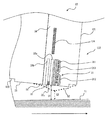
次に、本形態におけるTFCヘッド・スライダ12構成について説明を行う。図2は、ヘッド・スライダ12の空気流出端面(トレーリング側端面)121近傍におけるその一部構成を示す断面図である。磁気ディスク11は、図2の左から右に向かって回転する。ヘッド・スライダ12は、ヘッド素子部122とヘッド素子部122を支持するスライダ123とを備えている。なお、本形態のTFCは垂直磁気記録、水平磁気記録の双方のHDDに適用することができる。
Next, the configuration of the
ヘッド素子部122は、磁気ディスク11との間で磁気データを読み書きする。ヘッド素子部122は、リード素子32とそのトレーリング側のライト素子31とを備えている。ライト素子31は、ライト・コイル311を流れる電流で磁極312間に磁界を発生し、磁気データを磁気ディスク11に記録するインダクティブ素子である。リード素子32は磁気抵抗型の素子であって、磁気異方性を有する磁気抵抗素子32aを備え、磁気ディスク11からの磁界によって変化するその抵抗値によって磁気ディスク11に記録されている磁気データを読み出す。
The
ヘッド素子部122は、スライダ123を構成するアルチック基板に、メッキ、スパッタ、研磨などの薄膜形成プロセスを用いて形成される。磁気抵抗素子32aは、磁気シールド33a、bによって挟まれており、ライト・コイル311は絶縁膜313で囲まれている。また、ヘッド素子部122はライト素子31とリード素子32の周囲にアルミナなどの保護膜34を備え、ヘッド素子部122全体はその保護膜34で保護されている。なお、磁気ディスク11と対向する浮上面(ABS面:Air Bearing Surface)35上には、磁気ディスク11との短時間かつ軽微な接触が起こっても摩耗しないよう、またライト素子31およびリード素子32の腐食を防ぐため、厚さ数nmの炭素保護膜が形成されている。
The
ライト素子31およびリード素子32の近傍には、薄膜で形成された抵抗体によるヒータ124が薄膜プロセスを用いて形成されている。本例において、ヒータ124は、ヘッド素子部122の反磁気ディスク11側に位置している。例えば、薄膜抵抗体として、パーマロイ、厚さ0.5mm、幅3μmの細線を、奥行き60μm、幅60μmの領域に蛇行させ、間隙はアルミナで埋めてヒータ124を形成することができる。ヒータ124の抵抗値は、例えば、50Ωである。
In the vicinity of the
AE13がヒータ124に電流を流すと、ヒータ124の熱によってヘッド素子部122の近傍が突出変形する。非加熱時において、ヘッド・スライダ12のABS面は、S1で示される形状であり、ヘッド素子部122と磁気ディスクとの間の距離であるクリアランスは、C1で示されている。ヒータ124加熱時における突出形状S2を、図2に破線で示す。ヘッド素子部122が磁気ディスク11に近づき、このときのクリアランスC2は、クリアランスC1よりも小さい。
When the
ヘッド素子部122の熱損傷を避けるためにヒータ124はヘッド素子部122から浮上方向に離間して形成されているが、ヒータ124の周囲材料の熱膨張がヘッド素子部122の位置まで伝わり、ヘッド素子部122が磁気ディスク11に近づくように、その周囲材料が膨張する。なお、図2は概念図であり、寸法関係は正確ではない。例えば、突出面形状S2はナノメートル・オーダ(数ナノメートル)の突出量である。
In order to avoid thermal damage to the
本形態のHDD1は、ヘッド・スライダ12のターゲット・セクタへのアクセス時において、TFCのためのヒータ電流の供給タイミング制御にその特徴点を有している。図4に示すように、HDD1は、リードもしくはライトのために、現在トラック113aもしくは退避位置から、ターゲット・トラック113bにヘッド・スライダ12を移動(シーク)する。なお、現在トラックとターゲット・トラックが同一のときは、ヘッド・スライダ12はそのトラックにそのまま位置決めされる。
The
磁気ディスク11の記録面には、半径方向に所定幅を有し、同心円状に形成された複数本のトラック113が形成される。サーボ・データおよびユーザ・データは、トラックに沿って記録される。一つのトラックは、サーボ・データ間に複数のデータ・セクタを備えている。各サーボ・データは、トラック・アドレス及びトラック内のセクタ・アドレスの他、ヘッド・スライダ12を各トラックに位置決めするためのバースト・パターンを備えている。ヘッド・スライダ12はシーク中に各サーボ・データを読み出しながら移動し、HDD1は、この読み出されたサーボ・データを使用してシークを制御する。
A plurality of tracks 113 having a predetermined width in the radial direction and concentrically formed are formed on the recording surface of the
本形態のHDD1は、ターゲット・トラック113bに向けてシークを開始した後において、ヘッド・スライダ12(ヘッド素子部122)が、ターゲット・セクタに到着してそのターゲット・セクタにアクセス(データ読み出しもしくはデータ書き込み)を開始する前の特定のタイミングで、ヒータ124をONとする(通電を開始する)。その後、ヒータ124への通電を維持し、データ読み出しもしくはデータ書き込みを開始するタイミングにおいて、ヘッド素子部122が十分に突出しているようにする。これによって、最初のアクセス・セクタにおいても、データの読み出しもしくは書き込みを確実に行うことができる。
In the
一方、ヘッド・スライダ122がトラック間を高速に移動している間は、磁気ディスク11との衝突の可能性が高まるため、できるだけヘッド素子部122を突出させないことが好ましい。本形態のHDD1は、シークを開始した後、ヘッド・スライダ122がターゲット・トラックから特定のトラック数離れたトラックからターゲット・セクタにアクセスを行う間において、ヒータ124をONとする。これによって、ヘッド素子部122と磁気ディスク11との衝突の可能性を低減しつつ、TFCによる最初のアクセス・セクタからの確実なデータ読み出し/書き込みを行うことができる。
On the other hand, while the
特に好ましい態様として、本形態のHDD1は、シークにおけるフォローイング・モードに入った後に、ヒータ124をONとする。ターゲット・セクタへのアクセスにおいて、典型的には、HDC/MPU23は、ヘッド・スライダ12(ヘッド素子部122)を、現在トラックからターゲット・トラックに移動し(シーク)、さらに、ターゲット・トラック上においてヘッド・スライダを位置決めする。ターゲット・セクタがヘッド・スライダ12の下に来ると、ヘッド・スライダ12は、ターゲット・セクタにデータを書き込む(ライト)、あるいはターゲット・セクタからデータを読み出す(リード)。
As a particularly preferred aspect, the
シークにおいて、HDC/MPU23は、複数の異なる制御モードを備えている。具体的には、シーク・モード、セトリング・モードそしてフォローイング・モードの3モードである。シーク・モードは速度制御であって、ターゲット・セクタまでの残り距離に対してシーク速度を制御する。セトリング・モードは位置制御であって、ターゲット・セクタの位置と現在ヘッド・スライダ位置の差に基づいて、ヘッド・スライダ12を移動制御する。さらに、フォローイング・モードは位置制御と速度制御とを共に使用し、ヘッド・スライダ12の速度の誤差を蓄積し、それに係数をかけた値で現在の位置を補正しながら、ヘッド・スライダ12を位置制御する。
In seeking, the HDC /
HDC/MPU23は、シーク・モード制御によって現在トラック113aからヘッド・スライダ12の移動を開始する。ヘッド・スライダ124が、ターゲット・トラック113bから予め定められた距離だけ離れたトラックに到着すると、HDC/MPU23は、制御モードをシーク・モードからセトリング・モードに切換える。
The HDC /
ヘッド・スライダ12が、ターゲット・トラック113bにさらに近づき、ターゲット・トラック113bから予め定められた距離(トラック数)のトラックに到着したことに応答して、HDC/MPU23は、制御モードをセトリング・モードからフォローイング・モードに切換える。その後、ヘッド・スライダ12は、フォローイング・モード制御において、ターゲット・トラック113bに到着し、さらに、そのターゲット・トラック113bに位置決めされる。ヘッド・スライダ12がターゲット・トラック113bに到着してから、データを読み書きできる位置、つまり、データのリード/ライトが許可される状態に制御されるまでには、さらに、数サーボ・セクタが必要とされる。このデータを読み書きできる位置(状態)に制御されたタイミングで、シーク完了(シーク・コンプ)となる。
In response to the
このように、本形態のHDD1は、シーク・モードが、シークにおける最終モードであるフォローイング・モードに移行した後の所定のタイミングにおいて、ヒータ124に電流供給を開始する、つまり、ヒータ124をOFFからONに切換える。ヘッド・シークにおいて、シーク開始前、もしくは、シーク開始後の早すぎるタイミングでヒータ124をONとし、さらに、データの書き込みまでヒータ124を通電し続けると、ヘッド・スライダ12の突出部(ヘッド素子部122)と磁気ディスク11との衝突の可能性が高まる。特に、フォローイング・モードの前(シーク・モードとセトリング・モード)までは、ヘッド・スライダ12が大きく移動している。このため、ヘッド・スライダ12の膨張突出部が磁気ディスク11に衝突する可能性が高い。
As described above, the
これに対し、シーク・モードがフォローイング・モードに移行した後にヒータ124をOFFからONに切換え、ヒータ124への通電を続けてヘッド素子部122を突出させることによって、ヘッド・シークにおいて、破損しやすいヘッド素子部122と磁気ディスク11との衝突を効果的に抑制することができる。
On the other hand, after the seek mode shifts to the following mode, the
ここで、上述のように、ヒータ124をONとするタイミングの設定においては、ヘッド・スライダ12が最初のターゲット・セクタに到着したタイミングにおいて、ヘッド・素子部122が十分に熱膨張により突出していることが重要である。これによって、最初の数ターゲット・セクタにおける不十分なオーバーライトを防止することができる。従って、最初のターゲット・セクタにアクセスする直前にヒータ124をONとしても、十分な突出量を得ることができない可能性がある。
Here, as described above, in setting the timing when the
そこで、フォローイング・モードにおいてヒータ124をONとする、好ましいタイミングについて詳細に説明する。図4を参照して、データ・ライト・シーケンスにおける制御を説明する。HDC/MPU23は、ホスト5からライト・コマンドを受信すると、現在トラックもしくは退避位置から、ターゲット・トラックに向けてヘッド・スライダ12のシークを開始する(S11)。なお、以下においてはデータ・ライトについて説明するが、データ・リードにおいてもターゲット・セクタに到着するまでの処理は同様である。
Therefore, a preferable timing for turning on the
シークの最初において、HDC/MPU23は、シーク・モードにおいて、ヘッド・スライダ12を移動する(S12)。ヘッド・スライダ12がターゲット・トラックに近づき、予め定め設定されたトラック数だけ離れたトラックに到着すると、シーク・モードからセトリング・モードに移行する(S13)。例えば、ターゲット・トラックから100トラック離れたトラックに到着したタイミングで、HDC/MPU23はシーク・モードからセトリング・モードに移行する。
At the beginning of the seek, the HDC /
セトリング・モードにおいてヘッド・スライダを移動した後、予め定め設定されたトラック数だけ離れたトラックに到着したタイミングで、HDC/MPU23はセトリング・モードからフォローイング・モードに移行する(S14)。例えば、ターゲット・トラックから5トラック離れたトラックに到着すると、HDC/MPU23はフォローイング・モードを開始する。
After moving the head slider in the settling mode, the HDC /
フォローイング・モード制御下において、ヘッド・スライダ12がターゲット・トラックに到着すると(S15)、ライトをすることができる状態にあるかを、HDC/MPU23はサーボ・データの確認を行う(S16−S19)。具体的には、HDC/MPU23は、ヘッド素子部122が読み出した位置信号の値(位置誤差信号、PES:Position Error Signal)を使用して、ヘッド・スライダ12の速さ(ヘッド速さ)と、ターゲット・トラックから距離(ヘッド位置)のそれぞれが、基準範囲(ライト許可範囲)内にあることを確認する。位置信号は、サーボ・データのアドレス・データとバーストから決定することができる。ヘッド速さは、位置信号の差分から決定することができる。
Under the following mode control, when the
HDC/MPU23は、ヘッド速さとヘッド位置のそれぞれが、N回連続(N連続サーボ・データ)で基準範囲内である場合、HDC/MPU23はライトできる状態であると判定し、シークが完了する(S20)。サーボ・データがヘッド速さもしくはヘッド位置のいずれかの条件範囲から外れている場合、HDC/MPU23は、1回目のサーボ・データ確認から処理を繰り返す。回数Nは、設計によって適切な値が設定される。
The HDC /
シークが完了すると(S20)、HDC/MPU23は書き込みのための準備処理を行い(S21)、サーボ・データのアドレス・データ(グレイ・コード)を読み出してヘッド位置がターゲット・トラックから外れていないことを確認(S22)した後、最初のターゲット・セクタが到着するのを待つ。典型的には、書き込みのための準備処理(S21)のための、3サーボ・データ分の時間、そして、ヘッド位置がトラックから外れていないことを確認(S22)するために、3サーボ・データの時間を必要とする。ヘッド・スライダ12が最初のターゲット・セクタに到着すると、磁気ディスク11へのデータ書き込みのために、R/Wチャネル21をライト・モードにセットするライト・ゲート信号をアサートにセットする。
When the seek is completed (S20), the HDC /
ヘッド位置を確認(S22)してから、最も早いタイミングでの書き込みのために、典型的には、3サーボ・データ分の時間が設定されている。従って、ターゲット・トラックが256サーボ・データを備えている場合、ヘッド位置を確認(S22)してから、3から254サーボ・データ後にターゲット・セクタにヘッド・スライダ12が到着する。
Typically, a time corresponding to 3 servo data is set for writing at the earliest timing after confirming the head position (S22). Therefore, when the target track has 256 servo data, the
以上のライト・シーケンスにおいて、本形態のHDC/MPU23は、フォローイング・モードに入ってから(S14)、いずれかのタイミングでヒータ124をONとする。また、書き込み処理(S21)が開始された後では、ヒータ124による加熱時間が十分にとれず、ヘッド素子部122が十分に突出しない可能性がある。従って、フォローイング・モード開始(S14)から、シーク完了(S20)の間のいずれかのタイミングでヒータ124への通電を開始する。
In the above write sequence, the HDC /
好ましいタイミングの一つは、シーク完了時(S20)である(Timing_4)。シーク完了後にも数サーボ・セクタ分の時間(S21−23)が確保されているため、この時間内でヒータ124によって十分な加熱を行うことができる場合には、ヘッド素子部122と磁気ディスク11との間の衝突の危険性を大きく低減することができる。そこで、HDC/MPU23は、シークの完了に応答して、ヒータ124をONとする。シークが完了しているので、ヘッド・スライダ12が位置決めされ、ヘッド素子部122と磁気ディスク11との衝突の可能性をより低くすることができる。
One of the preferable timings is when the seek is completed (S20) (Timing_4). Since the time (S21-23) for several servo sectors is secured even after the seek is completed, if sufficient heating can be performed by the
あるいは、他の好ましい態様として、ターゲット・トラックに到着(Timing_3)したことに応答して、HDC/MPU23は、ヒータ124をONとする。シーク完了前であり、ヘッド素子部122を突出させる時間をより多く確保することができる一方、既にターゲット・トラックに到着しているため磁気ディスク11との衝突の可能性も低減でき、2つの異なる要求をバランスする。さらに好ましくは、HDC/MPU23がフォローイング・モードに入った(Timing_1)ことに応答して、HDC/MPU23はヒータ124の通電を開始する。フォローイング・モードにあるため、ヘッド・スライダ12が磁気ディスク11上を大きく動くことがなく、ヘッド素子部122と磁気ディスク11との衝突の危険性が小さい。また、特に、データの書き込みまでにヘッド素子部122を膨張、突出させるための十分な時間を確実に確保することができる。
Alternatively, as another preferred mode, the HDC /
これらの他、ヘッド位置とヘッド速さの確認ステップ(S16−19)の間のタイミング(Timing_2)において、ヒータ124をONとしてもよい。このように、制御変化のタイミングにおいてヒータ124をONとすることによって、タイマによって時間を計測することによってヒータ124を制御する手法などと比較してより容易にヒータ124の通電タイミングを制御することができる。
In addition to these, the
ここで、シーク・モードにかかわらず、ヘッド・スライダ12が、ターゲット・トラックから予め定められたトラック数(0を含む)離れたトラックに到着したことに応答して、ヒータ124をONとしてもよい。また、シークを開始してから、上述のタイミングでヒータ124をONとする前には、ヘッド素子部122の衝突をさけるためヒータ124を常にOFFとしておくことが好ましいが、サーボ・データを読む間の期間など、間欠的にヒータ124をONとしてもよい。
Here, regardless of the seek mode, the
ここで、ヒータ124に供給する電流量について説明する。ヘッド素子部122は、ヒータ124による熱以外にも、ライト素子のジュール熱によって突出する。そのため、HDC/MPU23は、好ましくは、磁気ディスク11からのデータ読み出し時とデータ書き込み時との間において、ヒータ124に流す電流量を変化させる。具体的には、HDC/MPU23は、磁気ディスク11にデータを書き込むためにライト素子にライト電流を流す間、データを読み出すときよりも小さい電流をヒータ124に供給し、その発熱量を小さくする。あるいは、HDC/MPU23は、データ書き込みの間は、ヒータ124の通電を停止する。これによって、ライト素子31とヒータ124とによるヘッド素子部122の突出を適切な量とすることができる。
Here, the amount of current supplied to the
これに対して、図5を参照して説明したターゲット・セクタへのアクセス前(実際の読み出しもしくは書き込み前)にヘッド素子部122と突出させるためにヒータ124へ供給する電流の値は、リード及びライトの双方の処理において同一の値を使用することができる。また、その電流量(電力量)は、データを読み出している間の電流量以上であることが好ましい。これによって、アクセス前にヘッド素子部122を迅速に突出させることができる。また、ターゲット・セクタへのアクセス前のヒータ電流量とデータを実際に読み出している間の電流量を同一とすることで、制御を容易なものとすることができる。
On the other hand, the value of the current supplied to the
つまり、リード・シーケンスにおいては、リード素子32はライト素子31のように発熱しないため、ヒータ電流の値を同一値に維持した状態で、磁気ディスク11からデータを読み出す。このように、磁気ディスク11からデータを読み出している期間におけるヒータ電流と、アクセス・セクタへの到着前のタイミングにおけるヒータ電流とを同じ値とすることで、ヘッド素子部122の突出量を適切なものとすることができると共に、ヒータ124制御(TFC)をより効率的に行う。
That is, in the read sequence, the
ライト・シーケンスにおいて、ライト素子31にライト電流を供給する前に、ヘッド素子部122を十分に突出させるため、上述にように大きいヒータ電流を供給する。また、データ書き込みのためのライト電流供給を開始すると、ヒータ124への供給電流量を小さくする、あるいは供給を停止してヒータ124をOFFする。これによって、ヘッド素子部122の過度の突出を防止する。
In the write sequence, before the write current is supplied to the
ここで、上述のように、熱膨張によるヘッド素子部122の突出量は、周囲温度によっても変化する。そのため、周囲温度に従ってヒータ電流を変化させることが好ましい。つまり、高温領域においては低温領域よりもヒータ電流を小さくする(ヒータ電流を0とすることを含む)。これによって、高温時にヘッド素子部122の突出量が多すぎることによって、ヘッド素子部122と磁気ディスク11とが衝突することを防止することができる。
Here, as described above, the protruding amount of the
あるいは、周囲温度に応じて、ヒータ124をONとするタイミングを変化させることができる。具体的には、HDD1はサーミスタなどの温度検出器を備え、検出された温度に応じて、ヒータ電流を制御する。例えば、温度領域を、低温、中温、高温の3つのセグメントに分割し、各セグメントとヒータ電流をONとするタイミングを対応づける。
Alternatively, the timing for turning on the
HDC/MPU23は、低温においてはフォローイング・モードに入いるタイミングでヒータ124をONとし、中温においてはターゲット・トラックに到着したタイミングでヒータ124をONとし、高温においてはシーク・コンプのタイミングでヒータ124をONとする。あるいは、高温においてはヒータ電流を供給しない設定としてもよい。なお、上述において、シーク動作においてTFCについて説明したが、現在トラックがターゲット・トラックと一致する場合、例えば、ヘッド素子部122が十分に突出するのを待つため、データ領域へのアクセス(読み出しもしくは書き込み)を1周分待つようにすることが好ましい。
The HDC /
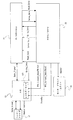
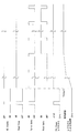
次に、本形態のTFCにおける、HDD1内の信号処理について具体的に説明する。上述のように、HDC/MPU23がTFC(ヒータ124制御)実行する。図5は、HDC/MPU23、R/Wチャネル21、AE13及びヘッド・スライダ12間の各伝送信号を示している。図6は、ライト・シーケンスにおけるそれら信号のタイミング・チャート、図7はリード・シーケンスにおけるそれら信号のタイミング・チャートである。なお、これらタイミング・チャートは各信号の変化を模式的に示すものであって、実際のHDDにおけるタイミングを正確に反映するものではない。
Next, signal processing in the
図5に示すように、HDC/MPU23は、R/Wチャネル21に対してライト・ゲート信号(Write_Gate)、リード・ゲート信号(Read_Gate)及びサーボ・ゲート信号(Servo_Gate)の各制御信号を出力する。ライト・ゲート信号(Write_Gate)は磁気ディスク11へのユーザ・データの書き込みを制御(書き込み指示)する信号であり、ライト・ゲート信号がON(ライト・ゲート開)となるとR/Wチャネル21がライト・モードにセットされ、磁気ディスク11へデータが書き込まれる。
As shown in FIG. 5, the HDC /
リード・ゲート信号(Read_Gate)は磁気ディスク11からのユーザ・データの読み出しを制御(読み出し指示)する信号であり、リード・ゲート信号がON(リード・ゲート開)となるとR/Wチャネル21がリード・モードにセットされ、磁気ディスク11からユーザ・データが読み出される。同様に、サーボ・ゲート信号(Servo_Gate)は磁気ディスク11からのサーボ・データの読み出しを制御する信号であって、その指示に従って磁気ディスク11からサーボ・データが読み出される。
The read gate signal (Read_Gate) is a signal for controlling (reading instruction) reading of user data from the
ヘッド・スライダ12はサーボ・データもしくはユーザ・データを読み出し、出力されたデータ信号(Data_Signal)は、AE13が増幅してR/Wチャネル21に転送する。R/Wチャネル21は、所定の信号処理を行い、サーボ・データ(Servo_Data)もしくはリード・ユーザ・データ(Read_Data)を生成し、HDC/MPU23に転送する。また、HDC/MPU23からのユーザ・ライト・データ(Write_Data)は、R/Wチャネル21が信号処理し、データ信号(Data_Signal)としてAE13に出力する。AE13はそれを増幅して、ヘッド・スライダ12に出力する。
The
HDC/MPU23は、取得したサーボ・データから、VCMに供給する電流値を決定し、それを示すデータであるDACOUTをモータ・ドライバ・ユニット24に出力する。モータ・ドライバ・ユニット24は、取得したDACOUTに応じたVCM電流をVCM15に供給する。
The HDC /
また、HDC/MPU23は、AE13のレジスタ・セット131にアクセスして、そのモード設定及びTFCの電流設定を行う。AE13は、電力低減のためのパワー・セーブ・モード(これをスタンバイ・モードと呼ぶ)を備えており、HDC/MPU23がレジスタAにデータをセットすることによって、スタンバイ・モードと通常動作モードとを切換える。AE13はスタンバイ・モードにおいてリード素子32へのバイアス電流を停止し、通常動作モードにおいてバイアス電流をリード素子32に供給する。
Further, the HDC /
また、本例のAE13は、HDC/MPU23がヒータ124の電流値(電力量:TFC Power)を設定するための2つのレジスタを備えている。レジスタBは、磁気ディスク11にデータを書き込んでいる期間におけるヒータ電流値を表すデータ(TFC_Current_Data (Write))を格納し、レジスタCは、磁気ディスク11からデータを読み出している期間におけるヒータ電流値を表すデータ(TFC_Current_Data (Read))を格納する。アクセス・セクタへの到着前におけるヒータ電流は、データを読み出している期間のヒータ電流値(レジスタCの値)と同様である。また、HDC/MPU23は、AE13に対してライト・ゲート信号(Write_Gate)を出力する。
In addition, the
AE13は、スタンバイがOFFつまり通常動作モードにおいて、ライト・ゲート信号(Write_Gate)がOFF(閉じている)とき、レジスタCに設定されているヒータ電流を供給する。具体的には、ユーザ・データもしくはサーボ・データの読み出し時において、このように、スタンバイがOFFでライト・ゲート信号がOFFである。さらに、ヘッド素子部122を十分に突出させるために、ターゲット・セクタへのアクセス前の上述のタイミングで、HDC/MPU23はAE13をこの状態にセットする。ヒータ124のON/OFF自体は、スタンバイ設定・データで制御することになる。
The
一方、AE13は、スタンバイがOFFつまり通常動作モードにおいて、ライト・ゲート信号(Write_Gate)がON(開いている)とき、レジスタBに設定されているヒータ電流を供給する。ライト・ゲート信号(Write_Gate)がONであるので、磁気ディスク11にデータを書き込んでいる期間であり、ライト・コイル331をライト電流が流れている
On the other hand, the
図6に示すライト・シーケンスのタイミング・チャートに示すように、シーク時を含め、サーボ・ゲート(Servo_Gate)がON(スタンバイがOFF)である磁気ディスク11からサーボ・データを読み出す期間において、レジスタCに設定されたヒータ電流をAE13はヘッド・スライダ12に供給する。シークにおいて、サーボ読み出し期間における通電によって、ヘッド素子部122は、実質的な突出は見せない。
As shown in the timing chart of the write sequence shown in FIG. 6, in the period of reading servo data from the
タイミングAにおいて、AE13はレジスタCに設定されているヒータ電流(Large)の供給を開始する。それに応じて、ヘッド素子部122の突出量が徐々に増加する。その後、最初のターゲット・セクタに到着してライト・ゲート(Write_Gate)がONとなってデータの書き込みを開始するまで、そのレジスタCの電流値を維持する。これによって、突出量が飽和値に維持される。データ書き込みの開始(ライト・ゲートON)に応答して、AE13はレジスタBに設定されたヒータ電流を供給する。図6に示すように、ライト電流によるヘッド素子部122の突出を考慮し、レジスタBの値による電流値(Small)はレジスCの電流値(Large)よりも小さい。その後、ライト・ゲートがON、つまりライト素子31にライト電流が供給されている間、AE13はレジスタBの電流値を供給する。その他の期間、つまりサーボ・データを読み出している間は、レジスCの電流値を供給する。
At timing A, the
HDC/MPU23は、レジスタB及びレジスタCの値を0もしくは周囲温度に応じた値にセットする。各レジスタへの設定タイミングは、シーク開始直前とすることが好ましい。本例のように、AE13が二つのレジスタを備えることによって、HDC/MPU23は、リードとライト応じたヒータ電流を制御することができる。
The HDC /
他の態様として、AE13が別のレジスタ(レジスタDとする)を備えることができる。このレジスタDは、ヒータ124のON/OFF制御のためのレジスタである。具体的には、レジスタDは、ヒータ124OFFを指示するデータ、ヒータ124ONであってレジスタBを示すデータ及びヒータ124ONであってレジスタCを示すデータのいずれかを格納する。AE13は、このレジスタDのデータに従って、ヒータ124電流の供給停止、もしくはレジスタB、レジスタCのヒータ電流を供給する。
As another aspect, the
つまり、HDC/MPU23が、これらのうちのいずれかのデータをヒータ124の各切換えタイミングでレジスタDにセットすることによって、AE13のヒータ電流供給を制御する。HDC/MPU23は、シークを開始する前にレジスタB及びレジスタCの値をセットし、これらの値はライト/リード・シーケンスが終了するまで維持される。なお、このAE13のレジスタ構成については、以下のリード・シーケンスにおいても同様に適用することができる。
That is, the HDC /
続いて、図7を参照して、リード・シーケンスにおけるTFCを説明する。各信号の関係はライト・シーケンスと同様である。リード・バイアス電流(Read Bias)は、AE13のスタンバイ/通常動作モードの変化に応じて変化する。また、シーク中において、サーボ・ゲートがONの期間において、AE13はレジスタCの電流値(Large)をヒータ124に供給する。これによって、ヘッド素子部122は、実質的に大きな突出は見せない。タイミングAにおいて、AE13はレジスタCの電流値(Large)の供給を開始し、リード・ゲート(Read Gate)がONとなるまでの間、その電流値を供給し続ける。それに応じて、ヘッド素子部122の突出量が徐々に増加し、飽和値に達する。リード・ゲートがONとなり磁気ディスク11からのデータ読み出しが開始された後も、AE13はレジスタCの電流値を供給し、ヘッド素子部122の突出量は飽和値に維持される。
Next, TFC in the read sequence will be described with reference to FIG. The relationship of each signal is the same as that of the write sequence. The read bias current (Read Bias) changes according to a change in the standby / normal operation mode of the
以上、本発明を好ましい実施形態を例として説明したが、本発明が上記の実施形態に限定されるものではない。当業者であれば、上記の実施形態の各要素を、本発明の範囲において容易に変更、追加、変換することが可能である。例えば、リード素子あるいはライト素子のみを備えるヘッド・スライダを実装するHDDに、本形態のTFCを適用することも可能である。 As mentioned above, although this invention was demonstrated taking preferable embodiment as an example, this invention is not limited to said embodiment. A person skilled in the art can easily change, add, and convert each element of the above-described embodiment within the scope of the present invention. For example, it is possible to apply the TFC of this embodiment to an HDD on which a head slider including only a read element or a write element is mounted.
1 ハードディスク・ドライブ、10 エンクロージャ、11 磁気ディスク
12 ヘッド・スライダ、14 スピンドル・モータ、15 ボイス・コイル・モータ
16 アクチュエータ、20 回路基板、21 リード・ライト・チャネル
22 モータ・ドライバ・ユニット、23 ハードディスク・コントローラ/MPU
31 ライト素子、32 リード素子、32a 磁気抵抗素子、33a、b シールド
34 保護膜、51 ホスト、113a 現在トラック
113b ターゲット・トラック、121 トレーリング側端面
122 ヘッド素子部、123 スライダ、124 ヒータ、311 ライト・コイル
312 磁極、313 絶縁膜
DESCRIPTION OF
31 Write element, 32 Read element, 32a Magnetoresistive element, 33a,
Claims (11)
前記スライダに配置されたヘッド素子部と、
前記ヘッド素子部をターゲット・トラックに向けてシークし、そのシークを異なる複数の制御モードにおいて実行するコントローラと、
前記スライダに配置され、前記シークの最終モードに入ってから前記ヘッド素子部がデータ領域へアクセスする前にON状態となり、そのヘッド素子部のデータ領域アクセスまで連続ON状態であり、そのヘッド素子部を熱膨張によって突出させて前記メディアとの間のクリアランスを調整するヒータと、を備えるデータ記憶装置、であって、
前記連続ON状態におけるヒータ電流値は、前記ヘッド素子部が前記データ領域からデータを読み出す間のヒータ電流値以上であり、
前記ヒータは、前記シークの完了に応答してON状態となり、そのヘッド素子部のデータ領域アクセスまで連続ON状態である、データ記憶装置。 A slider that floats on the rotating media,
A head element portion disposed on the slider;
A controller that seeks the head element portion toward a target track and executes the seek in different control modes;
The head element unit is arranged on the slider and is turned on before the head element unit accesses the data area after entering the seek final mode. A data storage device comprising: a heater that protrudes by thermal expansion and adjusts a clearance between the medium and
Heater current value in the continuous ON state, Ri heater current value or der while the head element reads data from said data area,
The data storage device , wherein the heater is turned on in response to completion of the seek and is continuously turned on until the data area access of the head element unit .
前記最終モードは前記位置・速度制御モードである、請求項1に記載のデータ記憶装置。 The controller includes a speed control mode using speed information, a position control mode using position information, and a position / speed control mode using position and speed information in the seek,
The data storage device according to claim 1, wherein the final mode is the position / speed control mode.
回転するメディア上を浮上するスライダを移動し、そのスライダに配置されたヘッド素子部をターゲット・トラックにシークし、そのシークを異なる複数の制御モードを順次切換えて実行し、
前記シークの最終モードに入ってから前記ヘッド素子部がデータ領域へアクセスする前にヒータをON状態に切換えそのヘッド素子部のデータ領域アクセスまでON状態を維持し、そのヘッド素子部を熱膨張によって突出させて前記メディアとの間のクリアランスを調整する方法、であって、
前記ヘッド素子部が前記データ領域からデータを読み出す間のヒータ電流値は、データを書き込む間のヒータ電流値よりも大きく、
前記連続ON状態におけるヒータ電流値は、前記ヘッド素子部が前記データ領域からデータを読み出す間のヒータ電流値以上であり、
ヒータは、前記シークの完了に応答してON状態となり、そのヘッド素子部のデータ領域アクセスまで連続ON状態である、方法 A control method in a data storage device, comprising:
Move the slider that floats on the rotating media, seek the head element section located on the slider to the target track, and execute the seek by sequentially switching between different control modes,
After entering the seek final mode, before the head element unit accesses the data area, the heater is turned on to maintain the ON state until the data area access of the head element unit, and the head element unit is thermally expanded. A method of adjusting the clearance between the medium by projecting,
The heater current value while the head element unit reads data from the data area is larger than the heater current value during data writing,
Heater current value in the continuous ON state, Ri heater current value or der while the head element reads data from said data area,
The heater is turned on in response to the completion of the seek, and is continuously turned on until the data area access of the head element unit.
前記ヘッドをターゲット・トラックに向けてシークするコントローラと、
前記シークを開始した後に前記ヘッドに配置され、前記ヘッドが前記ターゲット・トラックから予め定められたトラック数離れたトラックに到着したことに応答してON状態となりそのヘッドがデータ領域にアクセスするまでON状態を維持し、そのヘッドを熱膨張によって突出させて前記磁気ディスクとの間のクリアランスを調整するヒータと、
前記ヒータに供給する電流量を調整する調整回路と、を備えるデータ記憶装置であって、
前記コントローラは、前記シークを制御しながら前記調節回路にヒータ電流の供給についての指示を行い、
前記連続ON状態におけるヒータ電流値は、前記ヘッド素子部が前記データ領域からデータを読み出す間のヒータ電流値以上であり、
前記ヒータは、前記シークの完了に応答してON状態となり、そのヘッド素子部のデータ領域アクセスまで連続ON状態である、データ記憶装置。 A head that floats on a rotating magnetic disk;
A controller that seeks the head toward the target track;
Placed on the head after the seek is started and turned on in response to the head arriving on a track that is a predetermined number of tracks away from the target track and remains on until the head accesses the data area. A heater for maintaining the state and adjusting the clearance between the magnetic disk by projecting the head by thermal expansion;
A data storage device comprising: an adjustment circuit for adjusting an amount of current supplied to the heater;
The controller instructs the adjustment circuit to supply a heater current while controlling the seek,
Heater current value in the continuous ON state, Ri heater current value or der while the head element reads data from said data area,
The data storage device , wherein the heater is turned on in response to completion of the seek and is continuously turned on until the data area access of the head element unit .
Priority Applications (3)
| Application Number | Priority Date | Filing Date | Title |
|---|---|---|---|
| JP2005254817A JP4743855B2 (en) | 2005-09-02 | 2005-09-02 | Data storage device and control method thereof |
| US11/514,813 US7369349B2 (en) | 2005-09-02 | 2006-09-01 | Data storage device with heater, and control method therefor involving different control modes |
| CNB2006101290308A CN100409317C (en) | 2005-09-02 | 2006-09-04 | Data storage device and control method therefor |
Applications Claiming Priority (1)
| Application Number | Priority Date | Filing Date | Title |
|---|---|---|---|
| JP2005254817A JP4743855B2 (en) | 2005-09-02 | 2005-09-02 | Data storage device and control method thereof |
Publications (3)
| Publication Number | Publication Date |
|---|---|
| JP2007066487A JP2007066487A (en) | 2007-03-15 |
| JP2007066487A5 JP2007066487A5 (en) | 2008-10-09 |
| JP4743855B2 true JP4743855B2 (en) | 2011-08-10 |
Family
ID=37817609
Family Applications (1)
| Application Number | Title | Priority Date | Filing Date |
|---|---|---|---|
| JP2005254817A Expired - Fee Related JP4743855B2 (en) | 2005-09-02 | 2005-09-02 | Data storage device and control method thereof |
Country Status (3)
| Country | Link |
|---|---|
| US (1) | US7369349B2 (en) |
| JP (1) | JP4743855B2 (en) |
| CN (1) | CN100409317C (en) |
Families Citing this family (5)
| Publication number | Priority date | Publication date | Assignee | Title |
|---|---|---|---|---|
| JP2008243249A (en) * | 2007-03-26 | 2008-10-09 | Fujitsu Ltd | Storage device and control apparatus of storage device |
| JP2009004056A (en) * | 2007-06-25 | 2009-01-08 | Toshiba Corp | Magnetic disk device |
| US20090296270A1 (en) * | 2008-05-27 | 2009-12-03 | Jin Zhen | Thermal flyheight control heater preconditioning |
| CN103680521B (en) * | 2012-07-27 | 2017-04-12 | 希捷科技有限公司 | Heat assisted magnetic recording device with pre-heated write element |
| JP2022109629A (en) * | 2021-01-15 | 2022-07-28 | 株式会社東芝 | Magnetic head and disk apparatus equipped with the same |
Citations (4)
| Publication number | Priority date | Publication date | Assignee | Title |
|---|---|---|---|---|
| JPH1069747A (en) * | 1996-08-28 | 1998-03-10 | Nec Corp | Magnetic disk device |
| JP2004079126A (en) * | 2002-08-22 | 2004-03-11 | Toshiba Corp | Magnetic disk device |
| JP2004342151A (en) * | 2003-05-13 | 2004-12-02 | Hitachi Global Storage Technologies Inc | Floating control method of magnetic head slider, and magnetic disk device |
| JP2005135501A (en) * | 2003-10-30 | 2005-05-26 | Hitachi Global Storage Technologies Netherlands Bv | Thin film magnetic head slider, magnetic head support mechanism, magnetic disk device, and method for manufacturing magnetic head |
Family Cites Families (6)
| Publication number | Priority date | Publication date | Assignee | Title |
|---|---|---|---|---|
| JPH0520635A (en) * | 1991-07-11 | 1993-01-29 | Fujitsu Ltd | Magnetic head and magnetic disk device |
| JPH05250643A (en) | 1992-03-06 | 1993-09-28 | Nec Corp | Magnetic head, inspecting device for magnetic disk medium, and magnetic disk device |
| JP2002343049A (en) | 2001-05-17 | 2002-11-29 | Hitachi Ltd | Negative pressure slider having floating height regulating mechanism |
| JP3632025B2 (en) * | 2003-02-26 | 2005-03-23 | Tdk株式会社 | Thin film magnetic head, head gimbal assembly, and hard disk drive |
| US7088545B1 (en) * | 2005-06-28 | 2006-08-08 | Western Digital Technologies, Inc. | Disk drive decreasing head temperature to increase fly-height during seek operation |
| JP4413168B2 (en) * | 2005-07-19 | 2010-02-10 | 東芝ストレージデバイス株式会社 | Heater control method and storage device |
-
2005
- 2005-09-02 JP JP2005254817A patent/JP4743855B2/en not_active Expired - Fee Related
-
2006
- 2006-09-01 US US11/514,813 patent/US7369349B2/en not_active Expired - Fee Related
- 2006-09-04 CN CNB2006101290308A patent/CN100409317C/en not_active Expired - Fee Related
Patent Citations (4)
| Publication number | Priority date | Publication date | Assignee | Title |
|---|---|---|---|---|
| JPH1069747A (en) * | 1996-08-28 | 1998-03-10 | Nec Corp | Magnetic disk device |
| JP2004079126A (en) * | 2002-08-22 | 2004-03-11 | Toshiba Corp | Magnetic disk device |
| JP2004342151A (en) * | 2003-05-13 | 2004-12-02 | Hitachi Global Storage Technologies Inc | Floating control method of magnetic head slider, and magnetic disk device |
| JP2005135501A (en) * | 2003-10-30 | 2005-05-26 | Hitachi Global Storage Technologies Netherlands Bv | Thin film magnetic head slider, magnetic head support mechanism, magnetic disk device, and method for manufacturing magnetic head |
Also Published As
| Publication number | Publication date |
|---|---|
| JP2007066487A (en) | 2007-03-15 |
| US7369349B2 (en) | 2008-05-06 |
| US20070053103A1 (en) | 2007-03-08 |
| CN1925006A (en) | 2007-03-07 |
| CN100409317C (en) | 2008-08-06 |
Similar Documents
| Publication | Publication Date | Title |
|---|---|---|
| JP2007066488A (en) | Data storage device, and method of controlling same | |
| US7426089B2 (en) | Disk drive with heater for slider and control method thereof | |
| JP5032768B2 (en) | Magnetic head control device, magnetic head control method, and recording medium | |
| US8441909B1 (en) | Disk drive increasing laser power at beginning of write in heat assisted magnetic recording | |
| US7969681B2 (en) | Disk drive and control method thereof | |
| US8125728B2 (en) | Disk drive, head-slider and method for controlling clearance of a read element and a write element in the disk drive | |
| JP2007184023A (en) | Disk drive and its control method | |
| JP2008071417A (en) | Storage device, control method, and control circuit | |
| JP2009157987A (en) | Method for adjusting recess depth of head slider and disk drive device | |
| JP4743855B2 (en) | Data storage device and control method thereof | |
| JP4895560B2 (en) | Data storage | |
| JP2006085832A (en) | Control method of recording current and magnetic disk apparatus | |
| JP2007250162A (en) | Media drive device and its control method | |
| JP2006134377A (en) | Magnetic recording device and loading method | |
| KR100855973B1 (en) | Hard disk drive for controlling flying height of head and the method using the hard disk drive | |
| JP5833061B2 (en) | Apparatus, method and write head | |
| US7570446B2 (en) | Disk drive with improved format efficiency and control method thereof | |
| JP2006331634A (en) | Method, recording medium, and apparatus controlling domain characteristics of magneto-resistive sensor | |
| JP2004110918A (en) | Magnetic recording device and recording control method | |
| US9460745B1 (en) | Preheating a hard disk drive head slider for head switch seek | |
| JP2009134834A (en) | Disk drive device and clearance adjustment method thereof | |
| US20100328811A1 (en) | Method of controlling reading or writing operation of disk drive | |
| JP2004095010A (en) | Disk drive and control method based on its environment temperature | |
| JP2008171495A (en) | Disk drive unit and control method | |
| JP2007294034A (en) | Disk drive device and test method in its design |
Legal Events
| Date | Code | Title | Description |
|---|---|---|---|
| A521 | Written amendment |
Free format text: JAPANESE INTERMEDIATE CODE: A523 Effective date: 20080825 |
|
| A621 | Written request for application examination |
Free format text: JAPANESE INTERMEDIATE CODE: A621 Effective date: 20080825 |
|
| RD04 | Notification of resignation of power of attorney |
Free format text: JAPANESE INTERMEDIATE CODE: A7424 Effective date: 20100510 |
|
| A977 | Report on retrieval |
Free format text: JAPANESE INTERMEDIATE CODE: A971007 Effective date: 20110124 |
|
| A131 | Notification of reasons for refusal |
Free format text: JAPANESE INTERMEDIATE CODE: A131 Effective date: 20110201 |
|
| A521 | Written amendment |
Free format text: JAPANESE INTERMEDIATE CODE: A523 Effective date: 20110411 |
|
| TRDD | Decision of grant or rejection written | ||
| A01 | Written decision to grant a patent or to grant a registration (utility model) |
Free format text: JAPANESE INTERMEDIATE CODE: A01 Effective date: 20110506 |
|
| A01 | Written decision to grant a patent or to grant a registration (utility model) |
Free format text: JAPANESE INTERMEDIATE CODE: A01 |
|
| A61 | First payment of annual fees (during grant procedure) |
Free format text: JAPANESE INTERMEDIATE CODE: A61 Effective date: 20110509 |
|
| FPAY | Renewal fee payment (event date is renewal date of database) |
Free format text: PAYMENT UNTIL: 20140520 Year of fee payment: 3 |
|
| R150 | Certificate of patent or registration of utility model |
Free format text: JAPANESE INTERMEDIATE CODE: R150 |
|
| FPAY | Renewal fee payment (event date is renewal date of database) |
Free format text: PAYMENT UNTIL: 20140520 Year of fee payment: 3 |
|
| S533 | Written request for registration of change of name |
Free format text: JAPANESE INTERMEDIATE CODE: R313533 |
|
| FPAY | Renewal fee payment (event date is renewal date of database) |
Free format text: PAYMENT UNTIL: 20140520 Year of fee payment: 3 |
|
| R350 | Written notification of registration of transfer |
Free format text: JAPANESE INTERMEDIATE CODE: R350 |
|
| R250 | Receipt of annual fees |
Free format text: JAPANESE INTERMEDIATE CODE: R250 |
|
| R250 | Receipt of annual fees |
Free format text: JAPANESE INTERMEDIATE CODE: R250 |
|
| LAPS | Cancellation because of no payment of annual fees |