JP4743515B2 - Air conditioning system - Google Patents
Air conditioning system Download PDFInfo
- Publication number
- JP4743515B2 JP4743515B2 JP2006016588A JP2006016588A JP4743515B2 JP 4743515 B2 JP4743515 B2 JP 4743515B2 JP 2006016588 A JP2006016588 A JP 2006016588A JP 2006016588 A JP2006016588 A JP 2006016588A JP 4743515 B2 JP4743515 B2 JP 4743515B2
- Authority
- JP
- Japan
- Prior art keywords
- air
- duct
- conditioning
- ducts
- air conditioning
- Prior art date
- Legal status (The legal status is an assumption and is not a legal conclusion. Google has not performed a legal analysis and makes no representation as to the accuracy of the status listed.)
- Expired - Fee Related
Links
Images


Description
本発明は、工場やビル、展示場などの屋内の冷暖房を行う空調システムに関し、特に、未利用エネルギーの利用、省エネルギー、運転コストの低減、運転分析・評価及び地球環境に対する配慮等の各側面において最適な運転を可能とする空調システムに関する。 The present invention relates to an air-conditioning system that cools and heats indoors in factories, buildings, exhibition halls, etc., in particular, in each aspect such as use of unused energy, energy saving, reduction of operation cost, operation analysis / evaluation, and consideration for the global environment. The present invention relates to an air conditioning system that enables optimum operation.
従来、例えば工場に配備される空調システムにおいては、外気または還気を空調用ダクトに吸い込み、更に工場内に配備された複数の空調機により空調処理されたのち工場内の天井などに張り巡らされたダクトに送り込まれ、最終的にダクトの吹出し口から作業空間等に排出されるようになっている。
この種の従来の空調システムとして、例えば特許文献1及び2に記載のものがある。
Examples of this type of conventional air conditioning system include those described in Patent Documents 1 and 2.
このような空気搬送による空調システムにおいては、供給元である空調機、搬送ルートのダクト、吹出し口が建設時に固定されているので、吹出し場所が変更された場合、これに適合するように吹出し口を含むダクト系統を変更しなければならない。このため、吹出し場所の変更の都度、設備費や修繕費等のコストが掛かるという問題がある。これは、吹出し場所の変更が大規模で有れば有る程、高額のコストが掛かることになる。 In such an air-conditioning system using air conveyance, the air conditioner that is the supplier, the duct of the conveyance route, and the air outlet are fixed at the time of construction. Therefore, if the air outlet location is changed, the air outlet should be adapted to this. The duct system containing the must be changed. For this reason, there is a problem that costs such as equipment costs and repair costs are incurred every time the blowing location is changed. This means that the larger the change in the location, the higher the cost.
また、空調システムにおける制御として、吹出し場所の温度、湿度、風量、風速等の必要条件によって空調機の回転数を制御する省エネルギー方法がとられている。この他、複数の空調機が連携して並列運転を行う制御方法も考えられるが、搬送ダクト内の静圧のバランスや気流の乱れ等の要因からその並列運転の制御方法については確立されていない。
このため、上記のような吹出し場所の変更を行った場合、吹出し場所の要求量に応じた空調機個別の運転制御、例えばインバータによるファンの回転数制御等は行えるものの、吹出し場所の変化に応じて複数の空調機を選択運転したり、複数の空調機に連携して空調負荷を分担させたりする柔軟な省エネルギー制御を行うことができない。このため、空調対象となる全領域の最適な省エネルギー化を図ることができないという問題がある。
In addition, as control in the air conditioning system, an energy saving method is adopted in which the number of rotations of the air conditioner is controlled according to necessary conditions such as temperature, humidity, air volume, and wind speed at the blowing location. In addition to this, a control method in which a plurality of air conditioners cooperate to perform parallel operation is also conceivable, but the control method for parallel operation has not been established due to factors such as static pressure balance and airflow turbulence in the transfer duct. .
For this reason, when the air outlet location is changed as described above, although individual operation control of the air conditioner according to the required amount of the air outlet location, for example, the rotation speed control of the fan by the inverter can be performed, Thus, it is not possible to perform flexible energy saving control in which a plurality of air conditioners are selectively operated or the air conditioning load is shared in cooperation with the plurality of air conditioners. For this reason, there exists a problem that the optimal energy saving of the whole area | region used as air-conditioning object cannot be achieved.
本発明は、このような課題に鑑みてなされたものであり、吹出し場所変更に伴うダクト系統変更に掛かるコストを低減することができ、空調対象となる全領域の最適な省エネルギー化を図ることができる空調システムを提供することを目的としている。 The present invention, all SANYO been made in view of such problems, it is possible to reduce the cost of the ducting change due to blow out location changes, achieving optimum energy saving of the entire area to be air conditioned It aims to provide an air conditioning system that can.
上記目的を達成するために、本発明の請求項1による空調システムは、1乃至は複数の空調機の送風口から分岐されて延長されるダクトの空気の吹出し口を空調対象領域に設置してその領域の空調を行う空調システムにおいて、前記ダクトは、前記空調機の送風口に接続される複数の上層ダクトと、該上層ダクトと上下で交差させて格子状になるように、前記上層ダクトの下に所定間隔を設けて配置された複数の中層ダクトと、風量調整用のダンパが内蔵され、前記交差部分の上層ダクトおよび中層ダクトを接続する複数の接続ダクトと、1乃至は複数の前記吹出し口を有し、前記中層ダクトに設けられた複数の開閉自在な開口部に着脱自在に取付けられる最下層ダクトと、からなるマトリクス空調ダクトであることを特徴とする。 To achieve the above object, an air conditioning system according to claim 1 of the present invention, 1 to the installation the outlet of the air duct is extended is blower opening or al min Toki multiple air conditioners for air conditioning target area In the air conditioning system that performs air conditioning in the area, the duct includes a plurality of upper layer ducts connected to the air outlets of the air conditioner, and the upper layer so as to intersect with the upper layer ducts in a vertical pattern. A plurality of middle-layer ducts arranged at predetermined intervals below the duct, a plurality of dampers for airflow adjustment, a plurality of connection ducts connecting the upper-layer duct and the middle-layer duct of the intersection, and one or more It is a matrix air-conditioning duct having the outlet and comprising a lowermost layer duct detachably attached to a plurality of openable and closable openings provided in the middle layer duct .
この構成によれば、空調対象領域が例えば広い場所である場合に空調の需要箇所が移動又は変更になった場合、それに応じて吹出し口を有する最下層ダクトを移動、取外し、取付けすればよいので、容易に対応可能となる。従って、従来構成のように吹出し口が建設時に固定されているため、吹出し場所の変更の都度、吹出し口を含むダクト系統を変更することによって多額の設備費や修繕費等のコストが掛かるといったことが無くなり、吹出し場所変更に伴うダクト系統変更に掛かるコストを大幅に低減することができる。 According to this configuration, if the air-conditioning demand area is moved or changed when the air-conditioning target area is a wide area, for example, the lowermost duct having the outlet may be moved, removed, and attached accordingly. Can be easily accommodated. Therefore, because the outlet is fixed at the time of construction as in the conventional configuration, each time the outlet location is changed, changing the duct system including the outlet will require a large amount of equipment costs, repair costs, etc. Therefore, the cost for changing the duct system accompanying the change of the blowing location can be greatly reduced.
また、本発明の請求項2による空調システムは、請求項1において、前記マトリクス空調ダクトのうち格子状に固定された上層および中層ダクトの交差部分の交点を前記ダンパの位置座標と見做すと共に、その交点に前記空調機が位置すれば該当交点を、位置しなければ空調機に最寄りの交点を空調機の位置座標と見做し、空調が必要な空調対象領域に位置する各ダンパと、当該ダンパが内蔵されたダクトに繋がる空調機との距離を双方の位置座標からそれぞれ求めると共に各ダンパの各要求風量を求め、この求められた各距離に反比例すると共に各要求風量に比例する係数を空調機毎に求め、この求められた係数が大きいほど順位が高くなるように空調機に優先順位を付け、前記空調が必要な空調対象領域の全要求風量を、互いの静圧を均衡させた際の合計風量で供給可能な複数の空調機を前記優先順位に従って選択し、この選択された複数の空調機を運転する空調制御手段を備えていることを特徴とする。
この構成によれば、空調が必要な領域の全要求風量が供給できるように複数の空調機を所定の静圧を保ちながら連携運転することができるので、各空調機の動力を下げることができ、合計風量で賄うことにより効率の良い送風を行うことができる。これによって省エネルギー化を図ることができる。
An air conditioning system according to claim 2 of the present invention is the air conditioning system according to claim 1, wherein the intersection of the upper layer and middle layer ducts fixed in a lattice pattern in the matrix air conditioning duct is regarded as the position coordinate of the damper. If the air conditioner is located at the intersection, the corresponding intersection is regarded as the position coordinate of the air conditioner if the nearest intersection is not located, and each damper located in the air conditioning target area requiring air conditioning, obtains each request air volume of the dampers together determine the respective distances between the air conditioner connected to the duct where the damper is built from both coordinates, the coefficients proportional to each request air volume as well as inversely proportional to the distance which is the calculated The air conditioners are prioritized so that the higher the calculated coefficient is, the higher the order is, and the total required air volume in the air-conditioning target area where the air conditioning is required is equalized. Selected according to the priority plurality of air conditioners capable of supplying a total air volume when allowed to, characterized in that it comprises an air conditioning control means for operating a plurality of air conditioners that this is selected.
According to this configuration, since a plurality of air conditioners can be operated in a linked manner while maintaining a predetermined static pressure so that all required airflows in an area requiring air conditioning can be supplied, the power of each air conditioner can be reduced. Efficient ventilation can be performed by covering with the total air volume. This can save energy.
また、本発明の請求項3による空調システムは、請求項2において、前記空調制御手段は、前記空調が必要な空調対象領域の全要求風量を、互いの静圧を均衡させた際の合計風量で供給可能な複数の空調機の運転制御条件に応じたシミュレーションにより予測した予測エネルギー消費量と、同運転制御条件での運転時の実エネルギー消費量との差を、前記係数に反映させる制御を行うことを特徴とする。 The air conditioning system according to claim 3 of the present invention is the air conditioning system according to claim 2 , wherein the air conditioning control means uses the total required air volume of the air-conditioning target area that requires air conditioning as the total air volume when the static pressures are balanced with each other. Control that reflects the difference between the predicted energy consumption predicted by simulation according to the operation control conditions of a plurality of air conditioners that can be supplied in the above and the actual energy consumption during operation under the same operation control conditions in the coefficient. It is characterized by performing.
この構成によれば、より適正な係数を得ることが可能となるので、より省エネルギー化を図ることができる。 According to this configuration, it is possible to obtain a more appropriate coefficient, and thus energy saving can be further achieved.
以上説明したように本発明によれば、吹出し場所変更に伴うダクト系統変更に掛かるコストを低減することができ、空調対象となる全領域の最適な省エネルギー化を図ることができるという効果がある。 According to the present invention described above, it is possible to reduce the cost of the ducting change due to blow out location changes, there is an effect that it is possible to achieve an optimum energy saving of the entire area to be air conditioned .
以下、本発明の実施の形態を、図面を参照して説明する。
図1は、本発明の実施の形態に係る空調システムの構成を示す図である。
図1に示す空調システム10は、工場11の屋内に設けられた第1〜第3の空調機13−1〜13−3と、これら空調機13−1〜13−3の送風口に接続され、工場11の天井にマトリクス状に張り巡らされた空調ダクト15−1〜15−6、16−1〜16−n及び17と、各空調機13−1〜13−3の運転制御を行う空調制御部18とを備える。
Hereinafter, embodiments of the present invention will be described with reference to the drawings.
FIG. 1 is a diagram showing a configuration of an air conditioning system according to an embodiment of the present invention.
An
更に、空調システム10は、工場11の外に、第1〜第3の蒸発器21−1,21−2,21−3と、これら蒸発器21−1〜21−3の近傍に配置されたフード22−1,22−2,22−3に取り付けられると共に工場11の外壁を貫通して各空調機13−1〜13−3の吸気口に取り付けられたダクト23−1,23−2,23−3と、これらダクト23−1〜23−3の通気路中に配置された吸込ファン24−1,24−2,24−3と、各蒸発器21−1〜21−3を挟んだ各フード22−1〜22−3の対向位置に配置されたノズル装置25−1,25−2,25−3と、これらノズル装置25−1〜25−3の内部に配置された押込ファン26−1,26−2,26−3と、各蒸発器21−1〜21−3の温度を検出する温度センサ27−1,27−2,27−3と、ファン制御部28とを備えて構成されている。
Further, the
このような構成要素を備える空調システム10の特徴を、以下の(1)〜(6)にて説明する。
(1)冷気の回収。
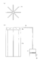
各蒸発器21−1〜21−3は、図2(a)のフィン部の平面図、(b)のフィン部の側面図に示すように、複数枚の板状のフィン21aが真上から見て星型に組合されて構成されている。更に、各フィン21aの内部は空洞となり互いの空洞が連接されており、図3に第1の蒸発器21−1を代表して示すように、コンクリート製の台座21bの上に固定された各フィン21aに液体窒素(又は液体酸素)を通す配管21cが組み合わされることによって、図示せぬ液体窒素タンクから矢印Y1aで示すように液体窒素が流入され、これが全てのフィン21aの内部を通り矢印Y1bで示すように排出される。
なお、その排出された液体窒素は、例えば図示せぬ貯蔵タンクに回収される等の構成で再利用されるようになっている。
Features of the
(1) Recovery of cold air.
Each of the evaporators 21-1 to 21-3 includes a plurality of plate-
The discharged liquid nitrogen is reused in a configuration such as being collected in a storage tank (not shown), for example.
各フィン21aの内部を液体窒素が通過する際に、フィン21aの周囲の空気が熱交換によって冷却され、気化熱である冷気が大量に発生する。この冷気は矢印Y2で示すように下方へ流れる。
この冷気をダクト23−1へ取り込むために、押込ファン26−1でノズル装置25−1の3つのノズルから矢印Y3で示すように空気を送風し、吸込ファン24−1によってフード22−1から吸込むようになっている。この冷気が吸込まれるまでの流れを矢印Y4で示した。
更に説明すると、その送風は、フィン21aにおいて霜が一番付着し易い液体窒素流入側の反対側で且つフィン21aの下半分位の高さから地面までの範囲に対して行っている。
When liquid nitrogen passes through the inside of each
In order to take this cold air into the duct 23-1, air is blown from the three nozzles of the nozzle device 25-1 by the pushing fan 26-1 as indicated by the arrow Y3, and from the hood 22-1 by the suction fan 24-1. Inhale. The flow until the cold air is sucked is indicated by an arrow Y4.
If it demonstrates further, the ventilation will be performed with respect to the range from the height of the lower half rank of the fin 21a to the ground on the opposite side to the liquid nitrogen inflow side where frost adheres most easily in the fin 21a.
これを実現するために、フード22−1を、蒸発器21−1の矢印Y1aで示す液体窒素の流入側で且つ下方の近傍位置に配置し、ノズル装置25−1を、蒸発器21−1の矢印Y1bで示す液体窒素の排出側で且つ下半分の近傍位置に配置している。
このように配置された押込ファン26−1と吸込ファン24−1とを、ファン制御部28により運転することによって、ノズル装置25−1から矢印Y3で示すフード22−1方向に送風が行われ、冷気が矢印Y4で示すように送風方向へ移動する。更に、フード22−1の開口付近は吸込ファン24−1で吸込み状態にあるので、その移動した冷気が効率良くフード22−1内に吸込まれ、矢印Y5で示すようにダクト23−1を通って空調機13−1へ送り込まれる。
In order to realize this, the hood 22-1 is arranged on the liquid nitrogen inflow side indicated by the arrow Y1a of the evaporator 21-1 and in the vicinity of the lower side, and the nozzle device 25-1 is connected to the evaporator 21-1. It is arranged on the liquid nitrogen discharge side indicated by the arrow Y1b in the vicinity of the lower half.
By operating the pushing fan 26-1 and the suction fan 24-1 arranged in this way by the
このように、蒸発器21−1の下部からファン26−1,24−1により押込み又は吸引することにより効率的に冷気を回収することが可能となる。ここでは、蒸発器21−1及びこの系統を代表して説明したが、他の蒸発器21−2,21−3系統においても同様である。
このように、各蒸発器21−1〜21−3の気化過程での気化熱の有効活用を図ることができる。
また、蒸発器21−1〜21−3から冷気が周囲に霧状の靄として発生しないので、従来のように道路上の視界が遮られ、歩行者や運転者の安全性が損なわれることも無くなる。換言すれば、蒸発器21−1〜21−3の気化過程で発生する靄による視界悪化が及ぼす人への危険性を防止することができる。
As described above, it is possible to efficiently collect the cold air by pushing or sucking the air from the lower portion of the evaporator 21-1 by the fans 26-1 and 24-1. Here, the evaporator 21-1 and this system have been described as representatives, but the same applies to the other evaporators 21-2 and 21-3.
Thus, effective utilization of the heat of vaporization in the vaporization process of each of the evaporators 21-1 to 21-3 can be achieved.
Moreover, since cold air does not generate | occur | produce from the evaporators 21-1 to 21-3 as a mist-like soot around, the view on a road is interrupted conventionally and the safety | security of a pedestrian or a driver | operator may be impaired. Disappear. In other words, it is possible to prevent the danger to the human being caused by the visual field deterioration caused by the soot generated in the vaporization process of the evaporators 21-1 to 21-3.
(2)押込及び吸込ファンの運転/停止制御。
蒸発器21−1〜21−3が複数台ある場合は、常時全てが運転されるとは限らず停止中のものも存在する。蒸発器21−1〜21−3が停止中の場合はフィン21aに液体窒素が流入されていないので、そのフィン表面温度を検出すれば運転/停止状態が分かる。
そこで、図1に示すように、温度センサ27−1〜27−3を各蒸発器21−1〜21−3の温度変化が最も顕著に現れる位置、例えば下面側に設置して蒸発器21−1〜21−3の温度を検出し、ファン制御部28へ伝送する。
(2) Pushing and suction fan operation / stop control.
When there are a plurality of evaporators 21-1 to 21-3, all of them are not always operated, and some are stopped. When the evaporators 21-1 to 21-3 are stopped, liquid nitrogen is not flowing into the
Therefore, as shown in FIG. 1, the temperature sensors 27-1 to 27-3 are installed at positions where the temperature changes of the evaporators 21-1 to 21-3 are most conspicuous, for example, the lower surface side. The temperature of 1-21-3 is detected and transmitted to the
ファン制御部28は、その検出温度が運転状態を示す温度(運転温度と称す)である場合に、押込及び吸込ファン26−1〜26−3,24−1〜24−3を運転する。一方、ファン運転中に検出温度が運転温度よりも高くなった場合、押込及び吸込ファン26−1〜26−3,24−1〜24−3を停止する。
このように、蒸発器21−1〜21−3が複数台ある場合に、それらの運転/停止を検出温度に応じて制御することによって、無駄な電力消費を費やすこと無く気化熱の有効活用を図ることができる。
また、押込及び吸込ファン26−1〜26−3,24−1〜24−3を、常時又は所定時間間隔で運転させるようにすれば、各フィン21aに霜が慢性的に付着して氷状に固化するのを初期の段階で防止することが可能となる。
The
As described above, when there are a plurality of evaporators 21-1 to 21-3, by effectively controlling the operation / stop of the evaporators according to the detected temperature, it is possible to effectively use the heat of vaporization without consuming wasteful power consumption. You can plan.
Further, if the pushing and suction fans 26-1 to 26-3, 24-1 to 24-3 are operated at all times or at predetermined time intervals, frost is chronically attached to the
上記構成の他、図4に示すように、各蒸発器21−1〜21−3に図示せぬタンクからの液体窒素が、バルブ切替制御部35により制御される選択バルブ34によって何れか又は全ての蒸発器21−1〜21−3へ選択的に流入される構成の場合は、次のようにファン運転/停止制御を行う。即ち、ファン制御部28によって、バルブ切替制御部35の切替制御信号をもとに押込及び吸込ファン26−1〜26−3,24−1〜24−3の運転/停止制御を行うようにする。
In addition to the above configuration, as shown in FIG. 4, any or all of the liquid nitrogen from the tank (not shown) is supplied to each of the evaporators 21-1 to 21-3 by the
例えば、液体窒素が第1の蒸発器21−1のみへ液体窒素を流入するための選択バルブ34の制御を行っている場合は、この制御信号を受けたファン制御部28が押込及び吸込ファン26−1,24−1のみを運転するように制御する。
このような制御によっても、上記同様に、無駄な電力消費を費やすこと無く気化熱の有効活用を図ることができる。
For example, when the control of the
Even with such control, as described above, it is possible to effectively use the vaporized heat without consuming unnecessary power consumption.
(3)蒸発器の霜取り。
図2(b)に示すように、温水を流入する配管36と、その流入された温水を複数のノズル38aから流出させる配管38とが接続された流水制御装置37を用いて、各フィン21aに霜が付着した場合、又は霜が付着して氷状に固化した場合、それを融かして除去するようにしてもよい。
このため、各フィン21aの上方に複数のノズル38aを配置し、これらノズル38aから各フィン21aに温水が落下するようにした。
これによって、フィン21aに霜が付着しないので、熱交換率が良くなり、前述のような靄の発生を防止することができる。また、温水を工場設備である炉の廃熱を利用して作れば無駄なエネルギーを費やすことがない。更に、外気温によっては、温水でなくとも常温の水で霜や氷を溶解することが可能となる。
(3) Defrosting the evaporator.
As shown in FIG. 2B, each
For this reason, a plurality of
Thereby, since frost does not adhere to the
(4)回収冷気と外気との混合制御。
上述のように、冷気を回収して空調機13−1〜13−3へ導入するが、この際、回収冷気の量が足りない場合、所定温度以上とならないように外気又は工場内の循環気を混ぜて必要量とする。このため、外気取り入れアルゴリズムに基づいた演算により外気の取り入れの可否及び取り入れ量を決定し、回収冷気と取り入れた外気を適切に混合する。
(4) Mixing control of recovered cold air and outside air.
As described above, the cold air is collected and introduced into the air conditioners 13-1 to 13-3. At this time, if the amount of the collected cold air is insufficient, the outside air or the circulating air in the factory is prevented so as not to exceed a predetermined temperature. To make the required amount. For this reason, whether or not the outside air can be taken in and the amount of the outside air are determined by calculation based on the outside air taking algorithm, and the recovered cold air and the outside air taken in are appropriately mixed.
このように、空調制御部18で混合制御を行う。この場合、回収冷気及び外気(又は循環気)における各々のエンタルピから各々を混合した場合のエンタルピをシミュレーション計算し、予め設定した値と比較することにより回収冷気と外気との混合比率を決定する。そして、その混合比率で回収冷気及び外気(又は循環気)が導入されて混合されるように空調機13−1〜13−3のダンパの開閉率を制御する。
これによって、回収冷気を有効に利用して工場11の空調を行うことができるので、空調における省エネルギー化を図ることができる。
In this way, the
As a result, the recovered cold air can be effectively used to air-condition the
(5)マトリクス空調ダクト構造。
図1に示すように、マトリクス空調ダクトは、工場11の作業スペースの天井に各々が水平且つ平行状態に配置された6本の上層ダクト15−1〜15−6と、これら上層ダクト15−1〜15−6の下に当該上層ダクトと平行で且つ直交状態、即ち上下で格子状になるように配置されたn本の中層ダクト16−1〜16−nと、これら中層ダクト16−1〜16−nの下に所定間隔で作業スペース全体に行き渡るように配置された多数の下層ダクト17とを備えて構成されている。
(5) Matrix air conditioning duct structure.
As shown in FIG. 1, the matrix air-conditioning duct includes six upper-layer ducts 15-1 to 15-6 arranged in a horizontal and parallel state on the ceiling of the work space of the
更に説明すると、各空調機13−1〜13−3に上層ダクト15−1〜15−6、中層ダクト16−1〜16−n、下層ダクト17を、格子状に多段階層別に配管し、例えば、各空調機13−1〜13−3に直結される最上層である上層ダクト15−1〜15−6を空気供給層、次の階層である中層ダクト16−1〜16−nを空気搬送階層、下層ダクト17を吹出し層として機能を分けた。つまり、下層ダクト17には1乃至は複数の吹出し口が設けられている。
More specifically, the upper layer ducts 15-1 to 15-6, the middle layer ducts 16-1 to 16-n, and the
また、上層ダクト15−1〜15−6と中層ダクト16−1〜16−nは、図5に示すように、上層及び中層ダクトの直交位置に垂直に配置された接続ダクト31によって通気状態に接続されている。接続ダクト31の内部には、VD(風量調節ダンパ)、MD(モータダンパ)等の開閉ダンパや、CAV(Constant Air Valve)、VAV(Variable Air Valve)等のエアバルブ、その他類する開閉装置(以降これらを総称してダンパ32と称す)が組み込まれており、このダンパ32で上層ダクト15−1〜15−6から中層ダクト16−1〜16−nへの風量を調整可能なようになっている。
Further, as shown in FIG. 5, the upper ducts 15-1 to 15-6 and the middle ducts 16-1 to 16-n are brought into a ventilation state by a
中層ダクト16−1〜16−nには、下層ダクト17を抜き差しして取り付けるための多数の開口部が設けられており、この開口部に下層ダクト17が取り付けられている。開口部は、下層ダクト17を取り付けない場合はバネ構造で自動的に開口を閉状態とする蓋で塞がれるようになっている。
このようにマトリクス空調ダクト構造とすることによって、例えば、工場11の製造ラインの変更等で空調の需要箇所が移動又は変更になった場合、それに応じて吹出し口を有する下層ダクト17を移動、取外し、取付けすればよいので、容易に対応可能となる。
The middle ducts 16-1 to 16-n are provided with a large number of openings for inserting and removing the
By adopting the matrix air-conditioning duct structure in this way, for example, when the air-conditioning demand location is moved or changed due to a change in the production line of the
従って、従来構成のように吹出し口が建設時に固定されているため、吹出し場所の変更の都度、吹出し口を含むダクト系統を変更することによって多額の設備費や修繕費等のコストが掛かるといったことを解消することができる。換言すれば、吹出し場所変更に伴うダクト系統変更に掛かるコストを大幅に低減することができる。特に、従来では、吹出し場所の変更が大規模で有れば有る程、高額のコストが掛かっていたが、本実施の形態では、その変更が大規模であってもそれほどコストを掛けないで対応することができる。 Therefore, because the outlet is fixed at the time of construction as in the conventional configuration, each time the outlet location is changed, changing the duct system including the outlet will require a large amount of equipment costs, repair costs, etc. Can be eliminated. In other words, it is possible to significantly reduce the cost for changing the duct system accompanying the change of the blowing location. In particular, in the past, the larger the change of the blowout place, the higher the cost. However, in this embodiment, even if the change is large, it can be handled without much cost. can do.
(6)空調機の連携運転制御。
この空調機の連携運転制御は空調制御部18に行い、上記のような吹出し場所の変更を行った場合、吹出し場所の変化に応じて複数の空調機13−1〜13−3を選択運転したり、各空調機13−1〜13−3に連携して空調負荷を分担させたりする柔軟な省エネルギー制御を行うものである。
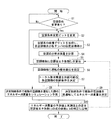
この空調制御部18による連携運転制御について、次のステップS1〜S10で説明する。
ステップS1において、空調条件が変更されたか否かを判断する。空調条件は、上記のような製造ラインの変更のような空調場所の物理的な変更で変わるが、この他、製造ラインの運転停止や作業時間帯など、空調対象場所において空調が必要か否かの状態(空調要否状態)に応じても変わる。
(6) Coordinated operation control of air conditioners.
This cooperative operation control of the air conditioner is performed by the air
The cooperative operation control by the air
In step S1, it is determined whether the air conditioning conditions have been changed. The air conditioning conditions change due to physical changes in the air-conditioning place such as changes in the production line as described above. In addition to this, whether air-conditioning is required at the air-conditioning target place, such as production line shutdown and work hours. It also changes depending on the state (air conditioning necessity state).
そこで、空調条件が変更されたか否かを判断する手段として、本実施の形態では、製造ラインの照明のオン/オフとした。即ち、照明電源19からの照明オン/オフ信号を受けて判断を行う。なお、その他、製造ラインの動力電源のオン/オフ、空調要否状態を人が手動で行う際の手動信号、空調要否状態をタイマで管理する際のタイマ信号、温湿度計からの信号などを受けて判断を行っても良い。
Therefore, in the present embodiment, the illumination of the production line is turned on / off as means for determining whether or not the air conditioning conditions have been changed. That is, a determination is made in response to an illumination on / off signal from the
また、空調条件が変更となったか否かの判断結果は、空調条件変更ビットを用いて示すようにした。
即ち、空調条件が変更された場合は、ステップS2において、空調条件変更ビットを「1」に変更する。また、後述で説明するステップS5で空調省エネ係数Ejを計算した後はステップS2で空調条件変更ビットを「0」とする。
In addition, the determination result as to whether or not the air conditioning condition has been changed is indicated using an air conditioning condition change bit.
That is, if the air conditioning condition is changed, the air conditioning condition change bit is changed to “1” in step S2. Further, after calculating the air conditioning energy saving coefficient Ej in step S5 described later, the air conditioning condition change bit is set to “0” in step S2.
空調条件変更ビットが「1」の場合は、ステップS3において、空調条件変更後に吹出しが必要なエリアの空調系、例えば図6に示すような空調系の座標グリッドを形成して各空調機13−1〜13−3及び各ダンパ32の位置を示す座標を求める。
即ち、マトリクス空調ダクト構造の上層ダクト15−1〜15−6及び中層ダクト16−1〜16−nを座標グリッドと見做し、これら交点から空調機13−1〜13−3の位置を示す座標と、接続ダクト31に設けられたダンパ32の位置を示す座標とを求める。
When the air conditioning condition change bit is “1”, in step S3, an air conditioning system in an area that needs to be blown out after the air conditioning condition is changed, for example, a coordinate grid of the air conditioning system as shown in FIG. The coordinates indicating the positions of 1-13-3 and the
That is, the upper layer ducts 15-1 to 15-6 and the middle layer ducts 16-1 to 16-n of the matrix air-conditioning duct structure are regarded as coordinate grids, and the positions of the air conditioners 13-1 to 13-3 are shown from the intersections. The coordinates and coordinates indicating the position of the
但し、空調条件変更後に吹出しが必要な空調系は、例えば照明オン/オフ信号と、この信号のオン/オフで分かるエリアとを対応付けておき、オンのエリアのみの空調系の座標グリッドを形成する。
上層ダクト15−1〜15−6と中層ダクト16−1〜16−nとの交点には、ダンパ32が存在するので、図6に示すように、上層ダクト15−1〜15−6を行方向の直線、中層ダクト16−1〜16−7を列方向の直線で表し、各々の交点をダンパ32の位置を示す座標とする。
However, for air conditioning systems that need to be blown out after changing the air conditioning conditions, for example, an illumination on / off signal is associated with an area that can be identified by the on / off of this signal to form a coordinate grid for the air conditioning system only in the on area. To do.
Since the
この例の場合、1行目の上層ダクト15−1と1列目の中層ダクト16−1との交点を座標(1,1)、1行目の上層ダクト15−1と2列目の中層ダクト16−2との交点を座標(1,2)、1行目の上層ダクト15−1と3列目の中層ダクト16−3との交点を座標(1,3)、1行目の上層ダクト15−1と4列目の中層ダクト16−4との交点を座標(1,4)、…、1行目の上層ダクト15−1とn列目の中層ダクト16−nとの交点を座標(1,n)とした。 In the case of this example, the intersection of the upper-layer duct 15-1 in the first row and the middle-layer duct 16-1 in the first row is represented by coordinates (1, 1), and the upper-layer duct 15-1 in the first row and the middle layer in the second column. The intersection point with the duct 16-2 is coordinate (1,2), and the intersection point between the upper-layer duct 15-1 in the first row and the middle-layer duct 16-3 in the third row is the coordinate (1,3), the upper layer in the first row. The intersection of the duct 15-1 and the middle-tier duct 16-4 in the fourth row is represented by coordinates (1, 4),... The intersection of the upper-tier duct 15-1 in the first row and the middle-tier duct 16-n in the n-th row It was set as a coordinate (1, n).
また、2行目の上層ダクト15−2と1列目の中層ダクト16−1との交点を座標(2,1)、2行目の上層ダクト15−2と2列目の中層ダクト16−2との交点を座標(2,2)、2行目の上層ダクト15−2と3列目の中層ダクト16−3との交点を座標(2,3)、2行目の上層ダクト15−2と4列目の中層ダクト16−4との交点を座標(2,4)、…、2行目の上層ダクト15−2とn列目の中層ダクト16−nとの交点を座標(2,n)とした。この他、3行目〜6行目の上層ダクト15−3〜15−6においても同様に中層ダクト16−1〜16−nとの交点をダンパ32の位置座標とする。各ダンパ32(記号DAで表す)に1行目のものから順に番号を付けると、i番目のダンパDA(i)の座標は(xi,yi)となる。
In addition, the intersection of the second-row upper-layer duct 15-2 and the first-row middle-layer duct 16-1 is represented by coordinates (2, 1), the second-row upper-layer duct 15-2 and the second-row middle-layer duct 16- 2 is the coordinate (2, 2), and the intersection of the second row of the upper duct 15-2 and the third row of the middle duct 16-3 is the coordinate (2, 3) of the second row of the upper duct 15- The intersection of the second and fourth rows of the middle-layer duct 16-4 is coordinate (2, 4),... The intersection of the second-row upper-layer duct 15-2 and the n-th row of middle-layer duct 16-n is coordinate (2 , N). In addition, in the upper-layer ducts 15-3 to 15-6 in the third to sixth rows, the intersections with the middle-layer ducts 16-1 to 16-n are set as the position coordinates of the
また、各空調機13−1〜13−3の位置座標は、空調機13−1〜13−3が上記の交点に位置すればその交点に定めるが、交点に位置しない場合は、空調機13−1〜13−3に最も近い上層ダクト15−1〜15−6と中層ダクト16−1〜16−nとの交点を座標とする。本例では空調機13−1〜13−3は3つであるが、これ以上存在する場合に空調機(記号AHで表す)に順に番号を付けると、j番目の空調機AH(j)の座標は(Xj,Yj)となる。 The position coordinates of the air conditioners 13-1 to 13-3 are determined at the intersections if the air conditioners 13-1 to 13-3 are located at the above intersections. The intersections of the upper ducts 15-1 to 15-6 and the middle ducts 16-1 to 16-n that are closest to -1 to 13-3 are coordinates. In this example, there are three air conditioners 13-1 to 13-3, but when there are more than this, if the air conditioners (represented by the symbol AH) are numbered sequentially, the j-th air conditioner AH (j) The coordinates are (Xj, Yj).
次に、ステップS4において、空調系の要求風量の計算を行う。この計算は、まず、各ダンパ32における要求風量を計算し、これらを加算して空調系でのトータル要求風量を計算する。
例えば製造ラインにおける吹出し口の数は10個などと決まっており、この個数分の風量が各ダンパ32の要求風量となる。1つのダンパDA(i)の要求風量Qiは次式(1)で表される。
Qi=ki×Qi_max …(1)
但し、ki:ダンパ開度係数、Qi_max:最大風量である。
Next, in step S4, the required air volume of the air conditioning system is calculated. In this calculation, first, the required air volume in each
For example, the number of outlets in the production line is determined to be 10 or the like, and the air volume for this number is the required air volume for each
Qi = ki × Qi_max (1)
However, ki: damper opening coefficient, Qi_max: maximum air volume.
ダンパ開度係数kiと最大風量Qi_maxとの関係は、例えば10個の吹出し口の風量を賄うためにはダンパ開度を70%とする等の関係に繋がるものである。また、空調機から送風する場合、最も近い吹出し口に最大風量Qi_maxで送風するのが最も効率が良く、遠くの吹出し口へ送風するのは効率が悪いことが分かっている。
1つのダンパDA(i)の要求風量Qiを計算した後は、Q_total=ΣQiにより空調系でのトータル要求風量Q_totalを計算する。
The relationship between the damper opening coefficient ki and the maximum air volume Qi_max leads to a relationship in which, for example, the damper opening is set to 70% in order to cover the air volume of 10 outlets. In addition, it has been found that when the air is blown from the air conditioner, it is most efficient to blow to the nearest outlet with the maximum air volume Qi_max, and it is inefficient to blow to the far outlet.
After calculating the required air volume Qi of one damper DA (i), the total required air volume Q_total in the air conditioning system is calculated by Q_total = ΣQi.
次に、ステップS5において、各空調機AH(j)における空調省エネ係数Ejを下式(2)より算出する。
空調省エネ係数Ejとは、複数の空調機を連携運転する際に極力省エネルギーにて運転するための指標となる係数であり、下式(3)で算出される空調機からダンパまでの距離(空調機ダンパ間距離)Pi,jが小さいほど大きくなり、また、要求風量Qiが大きいほど大きくなるものである。
Next, in step S5, an air conditioning energy saving coefficient Ej in each air conditioner AH (j) is calculated from the following equation (2).
The air-conditioning energy-saving coefficient Ej is a coefficient that serves as an index for operating a plurality of air-conditioners in an energy-saving manner as much as possible. The distance from the air-conditioner to the damper (air-conditioning) calculated by the following equation (3) The distance between the machine dampers (Pi, j) increases as the required air volume Qi increases.
Ej=Σ(m×a×Pmin/Pi,j+n×b×Qi/Qmax) …(2)
m:距離重み係数、n:風量重み係数。
Pminは空調系の最小距離であり、Pmin=MIN(Pi,j)。
Qmaxは空調系の最大風量であり、Qmax=MAX(Qi_max)。
a,b:補正係数(通常はa,b共に1に設定されている)。
Pi,jは、空調機ダンパ間距離であり、AH(j)とDA(i)の空調機ダンパ間距離Pi,jは、次式(3)から求められる。
Pi,j=ABS(Xj−xi)+ABS(Yj−yi) …(3)
但し、ABS:絶対値を求める関数である。
Ej = Σ (m × a × Pmin / Pi, j + n × b × Qi / Qmax) (2)
m: distance weight coefficient, n: air volume weight coefficient.
Pmin is the minimum distance of the air conditioning system, and Pmin = MIN (Pi, j).
Qmax is the maximum air volume of the air conditioning system, and Qmax = MAX (Qi_max).
a, b: correction coefficients (normally, both a and b are set to 1).
Pi, j is the distance between the air conditioner dampers, and the distance Pi, j between the air conditioner dampers of AH (j) and DA (i) is obtained from the following equation (3).
Pi, j = ABS (Xj-xi) + ABS (Yj-yi) (3)
However, ABS: a function for obtaining an absolute value.
また、m、nは、m+n=1となるように設定され、それら係数の決め方はバランスを考慮して決定される。この理由を説明する。要求風量Qiと空調機ダンパ間距離Pi,jとの関係は1:1だが、実際はダクトの空気漏れなどのロス等が原因となり必ずしもそうでない。そこで、その誤差を調整するための風量Qiと距離Pi,jとにおける係数m、nが必要となる。 Further, m and n are set so that m + n = 1, and how to determine these coefficients is determined in consideration of balance. The reason for this will be explained. The relationship between the required air volume Qi and the distance between the air conditioner dampers Pi, j is 1: 1, but this is not necessarily the case because of a loss such as air leakage from the duct. Therefore, coefficients m and n in the air volume Qi and the distance Pi, j for adjusting the error are required.
次に、ステップS6において、各空調機を運転する際の優先順位を空調機毎に付ける。これは、上述のように算出された空調省エネ係数Ejが大きいほど優先順位が高くなるように優先順位を付ける。空調省エネ係数Ejが同じものは空調能力の小さいものを高優先順位とする。
次に、ステップS7において、空調エリア決定済みのトータル要求風量Q_totalを供給可能な複数の空調機13−1〜13−3の制御条件を決定する。これは、トータル要求風量Q_totalが供給できるように複数の空調機13−1〜13−3を同時に運転する場合、所定の静圧を保ちながら連携運転するための制御条件である。
Next, in step S6, priority is given to each air conditioner when operating each air conditioner. This assigns priorities such that the higher the air conditioning energy saving coefficient Ej calculated as described above, the higher the priority. Those having the same air-conditioning energy saving coefficient Ej are given high priority when the air-conditioning capacity is small.
Next, in step S7, control conditions for the plurality of air conditioners 13-1 to 13-3 capable of supplying the total required air volume Q_total for which the air conditioning area has been determined are determined. This is a control condition for cooperative operation while maintaining a predetermined static pressure when the plurality of air conditioners 13-1 to 13-3 are simultaneously operated so that the total required air volume Q_total can be supplied.
更に説明すると、インバータ制御で何パーセント運転した時に必要な静圧−風量となるかは空調機毎に予め分かっているので、必要な静圧−風量となるパラメータに応じて(必要な静圧−風量となるように)各空調機をインバータ制御する。
風量と動力との関係は3乗の関係にある。動力を下げるためには風量を落した方が良く、風量を落として複数台で送風した方が効率が良い。つまり、ある風量を1台で賄うよりも複数台で賄った方が効率が良い。従来は例えば5台全てを運転してインバータ制御しているが、これを3台運転するようにして効率アップを図るようにするには、どのような制御条件で何台運転すればよいか決定する。
More specifically, since it is known in advance for each air conditioner that the required static pressure-air volume when the inverter is operated in accordance with the inverter control depends on the parameter for the required static pressure-air volume (necessary static pressure- Each air conditioner is inverter-controlled so that the air volume is the same.
The relationship between the air volume and power is a cube relationship. In order to lower the power, it is better to reduce the air volume, and it is more efficient to reduce the air volume and blow air with a plurality of units. In other words, it is more efficient to cover a certain air volume with a plurality of units than to cover with a single unit. Conventionally, for example, all five units are operated and inverter controlled, but in order to increase efficiency by operating these three units, determine how many units should be operated under what control conditions To do.
その制御条件を決定する場合、まず、各空調機13−1〜13−3のファンの静圧−風量の関数を決定する。この決定に際しては、空調機ファンの仕様上の静圧−風量の関数を参考にし、空調機の経年劣化及びその他条件を加味しながら関数及び各種パラメータを決定し、これを空調機ファンの静圧−風量関数と定義する。この静圧−風量関数の設定に際しては、実機における静圧−風量の実験によるデータも加味したものとする。 When determining the control conditions, first, the function of the static pressure-air volume of the fans of the air conditioners 13-1 to 13-3 is determined. When making this decision, refer to the function of static pressure-air volume in the specifications of the air conditioner fan, determine the function and various parameters while taking into account the aging of the air conditioner and other conditions, and use this as the static pressure of the air conditioner fan. -It is defined as an airflow function. In setting the static pressure-air volume function, it is assumed that data from an experiment of static pressure-air volume in an actual machine is taken into consideration.
次に、上記の優先順位1及び2の例えば空調機13−1,13−2について静圧を均衡させながら供給できる風量をQ_supplyとし、静圧の高い値から順にQ_total<Q_supplyとなる条件を導き出す。但し、空調機の最低周波数まで計算しても風量が満たされない場合には、次の優先度3、4、…の空調機を1台ずつ順々に条件にいれなから解が得られるまで計算を繰り返す。最終的に得られた解を制御条件とする。
Next, let Q_supply be the amount of air that can be supplied while balancing the static pressure for the air conditioners 13-1 and 13-2 having the priorities 1 and 2 described above, and derive the condition of Q_total <Q_supply in order from the highest static pressure. . However, if the air volume is not satisfied even after calculating to the lowest frequency of the air conditioner, calculate until the solution is obtained because the air conditioners of the
換言すると、空調省エネ係数Ejが大きい上位2台の空調機13−1,13−2の静圧を均衡させた際のトータル供給風量Q_supplyが、要求ダクト系統全体の必要風量であるトータル要求風量Q_totalを賄えれば、それら空調機13−1,13−2を使用する。また、トータル要求風量Q_totalを賄えなければ、3台目、4台目、…を使用してゆく。
なお、トータル要求風量Q_totalを賄えない場合に、各空調機の静圧を賄えるまで下げてもよい。これでも賄えなければ、上記の通り3台目、4台目、…を使用する。
In other words, the total required air volume Q_supply when the static pressures of the top two air conditioners 13-1 and 13-2 having a large air conditioning energy saving coefficient Ej are balanced is the total required air volume Q_total that is the required air volume of the entire required duct system. If these can be covered, the air conditioners 13-1 and 13-2 are used. If the total required air volume Q_total cannot be met, the third, fourth,... Are used.
If the total required air volume Q_total cannot be covered, it may be lowered until the static pressure of each air conditioner can be covered. If this is not possible, use the third, fourth, ... as described above.
次に、ステップS8において、上記決定された制御条件によって複数の空調機13−1,13−2を運転した場合のエネルギー消費量を、シミュレーションにより予測する。
また、ステップS9において、上記決定された制御条件によって複数の空調機13−1,13−2を実際に運転する。この時のエネルギー消費量を測定する。
Next, in step S8, the energy consumption amount when the plurality of air conditioners 13-1 and 13-2 are operated under the determined control conditions is predicted by simulation.
In step S9, the plurality of air conditioners 13-1 and 13-2 are actually operated according to the determined control conditions. The energy consumption at this time is measured.
そして、ステップS10において、上記の予測エネルギー消費量と実エネルギー消費量とを比較し、ニューラルネットワーク等の演算処理装置を用いてエネルギーの予測値と実測値との差を、空調省エネ係数Ejの式(2)における係数a,bの補正に反映させる。これによって、より適正な空調省エネ係数Ejを得ることが可能となる。
また、実際の複数の空調機13−1,13−2の連携運転制御は、上記ステップS1〜S10の処理ループにおいて空調省エネ係数Ejが収束した時点で、このEjを用いてステップS9の実運転を行うようにする。
In step S10, the predicted energy consumption is compared with the actual energy consumption, and the difference between the predicted energy value and the actual measured value is calculated using an arithmetic processing unit such as a neural network, and the air conditioning energy saving coefficient Ej is calculated. This is reflected in the correction of the coefficients a and b in (2). This makes it possible to obtain a more appropriate air conditioning energy saving coefficient Ej.
Further, in the actual cooperative operation control of the plurality of air conditioners 13-1 and 13-2, when the air conditioning energy saving coefficient Ej converges in the processing loop of steps S1 to S10, the actual operation of step S9 is performed using this Ej. To do.
以上説明したように本実施の形態の空調システム10によれば、工場11の吹出し場所変更に伴うダクト系統変更に掛かるコストを低減することができ、また、空調対象となる全領域の最適な省エネルギー化を図ることができる。
According to this embodiment the air-
10 空調システム
11 工場
13−1〜13−3 空調機
15−1〜15−6 上層ダクト
16−1〜16−n 中層ダクト
17 下層ダクト
18 空調制御部
19 照明電源
21−1〜21−3 蒸発器
21a フィン
21b 台座
21c,36,38 配管
22−1〜22−3 フード
23−1〜23−3 ダクト
24−1〜24−3 吸込ファン
25−1〜25−3 ノズル装置
26−1〜26−3 押込ファン
27−1〜27−3 温度センサ
28 ファン制御部
31 接続ダクト
32 ダンパ
34 選択バルブ
35 バルブ切替制御部
37 流水制御装置
38a ノズル
DESCRIPTION OF
Claims (3)
前記ダクトは、前記空調機の送風口に接続される複数の上層ダクトと、該上層ダクトと上下で交差させて格子状になるように、前記上層ダクトの下に所定間隔を設けて配置された複数の中層ダクトと、風量調整用のダンパが内蔵され、前記交差部分の上層ダクトおよび中層ダクトを接続する複数の接続ダクトと、1乃至は複数の前記吹出し口を有し、前記中層ダクトに設けられた複数の開閉自在な開口部に着脱自在に取付けられる最下層ダクトと、からなるマトリクス空調ダクトであることを特徴とする空調システム。 1 in an air conditioning system for the air conditioning of the area by installing the outlet of the air duct is extended is blower opening or al min Toki multiple air conditioners in the air-conditioned area,
The ducts are arranged with a plurality of upper layer ducts connected to the air outlet of the air conditioner, and at a predetermined interval below the upper layer ducts so as to intersect with the upper layer ducts in a lattice shape. A plurality of middle-layer ducts, a damper for adjusting airflow, and a plurality of connection ducts for connecting the upper-layer duct and the middle-layer duct at the intersecting portion, and one or a plurality of outlets, are provided in the middle-layer duct. air conditioning system characterized by being a plurality of bottom layer duct removably attached to closable opening has a matrix conditioning duct made of.
Priority Applications (1)
| Application Number | Priority Date | Filing Date | Title |
|---|---|---|---|
| JP2006016588A JP4743515B2 (en) | 2006-01-25 | 2006-01-25 | Air conditioning system |
Applications Claiming Priority (1)
| Application Number | Priority Date | Filing Date | Title |
|---|---|---|---|
| JP2006016588A JP4743515B2 (en) | 2006-01-25 | 2006-01-25 | Air conditioning system |
Publications (2)
| Publication Number | Publication Date |
|---|---|
| JP2007198655A JP2007198655A (en) | 2007-08-09 |
| JP4743515B2 true JP4743515B2 (en) | 2011-08-10 |
Family
ID=38453424
Family Applications (1)
| Application Number | Title | Priority Date | Filing Date |
|---|---|---|---|
| JP2006016588A Expired - Fee Related JP4743515B2 (en) | 2006-01-25 | 2006-01-25 | Air conditioning system |
Country Status (1)
| Country | Link |
|---|---|
| JP (1) | JP4743515B2 (en) |
Families Citing this family (2)
| Publication number | Priority date | Publication date | Assignee | Title |
|---|---|---|---|---|
| JP2013181716A (en) * | 2012-03-02 | 2013-09-12 | Ohbayashi Corp | Air conditioning system and air conditioning method for server room |
| JP7379552B2 (en) * | 2022-01-31 | 2023-11-14 | トリニティ工業株式会社 | Air conditioning system for painting equipment |
Citations (10)
| Publication number | Priority date | Publication date | Assignee | Title |
|---|---|---|---|---|
| JPS5066349U (en) * | 1973-10-22 | 1975-06-14 | ||
| JPS51145157A (en) * | 1975-06-10 | 1976-12-13 | Kanto Sanso Kogyosho:Kk | Factory cooler system |
| JPS54142854A (en) * | 1978-04-28 | 1979-11-07 | Hitachi Plant Eng & Constr Co Ltd | Air conditioning system |
| JPS5742390U (en) * | 1980-08-25 | 1982-03-08 | ||
| JPS60128240U (en) * | 1984-02-06 | 1985-08-28 | 高砂熱学工業株式会社 | air conditioning equipment |
| JPH03177744A (en) * | 1989-12-06 | 1991-08-01 | Hitachi Ltd | Air conditioner |
| JPH08285323A (en) * | 1995-04-11 | 1996-11-01 | Iwatani Internatl Corp | Low-temperature exercise room |
| JPH09159327A (en) * | 1995-12-06 | 1997-06-20 | Hitachi Ltd | Refrigerating machine |
| JP2000227246A (en) * | 1999-02-03 | 2000-08-15 | Sanyo Electric Co Ltd | Air-conditioner |
| JP2003501610A (en) * | 1999-06-08 | 2003-01-14 | プラジット インターナショナル エヌ.ヴイ. | Method and apparatus for forming individually controlled air conditioning in indoor separation section having primary air conditioning apparatus |
Family Cites Families (3)
| Publication number | Priority date | Publication date | Assignee | Title |
|---|---|---|---|---|
| US3848599A (en) * | 1973-10-12 | 1974-11-19 | Kendall & Co | Contourable diaper |
| JPS5742390A (en) * | 1980-12-03 | 1982-03-09 | Yasukichi Okazaki | Continuous water producing apparatus |
| JPS60128240A (en) * | 1983-12-15 | 1985-07-09 | Kubota Ltd | Ceramic-high chromium cast iron composite body |
-
2006
- 2006-01-25 JP JP2006016588A patent/JP4743515B2/en not_active Expired - Fee Related
Patent Citations (10)
| Publication number | Priority date | Publication date | Assignee | Title |
|---|---|---|---|---|
| JPS5066349U (en) * | 1973-10-22 | 1975-06-14 | ||
| JPS51145157A (en) * | 1975-06-10 | 1976-12-13 | Kanto Sanso Kogyosho:Kk | Factory cooler system |
| JPS54142854A (en) * | 1978-04-28 | 1979-11-07 | Hitachi Plant Eng & Constr Co Ltd | Air conditioning system |
| JPS5742390U (en) * | 1980-08-25 | 1982-03-08 | ||
| JPS60128240U (en) * | 1984-02-06 | 1985-08-28 | 高砂熱学工業株式会社 | air conditioning equipment |
| JPH03177744A (en) * | 1989-12-06 | 1991-08-01 | Hitachi Ltd | Air conditioner |
| JPH08285323A (en) * | 1995-04-11 | 1996-11-01 | Iwatani Internatl Corp | Low-temperature exercise room |
| JPH09159327A (en) * | 1995-12-06 | 1997-06-20 | Hitachi Ltd | Refrigerating machine |
| JP2000227246A (en) * | 1999-02-03 | 2000-08-15 | Sanyo Electric Co Ltd | Air-conditioner |
| JP2003501610A (en) * | 1999-06-08 | 2003-01-14 | プラジット インターナショナル エヌ.ヴイ. | Method and apparatus for forming individually controlled air conditioning in indoor separation section having primary air conditioning apparatus |
Also Published As
| Publication number | Publication date |
|---|---|
| JP2007198655A (en) | 2007-08-09 |
Similar Documents
| Publication | Publication Date | Title |
|---|---|---|
| JP4735690B2 (en) | Data center | |
| CN103075783B (en) | Air-side free cooling system and data center | |
| JP5185319B2 (en) | Air conditioning system and air conditioning control method for server room management | |
| JP5204702B2 (en) | Air conditioning system in a building with many heat generating devices | |
| JP5855895B2 (en) | Air conditioning systems for communication / information processing equipment rooms, etc. | |
| KR20110048099A (en) | Ventilation apparatus of heat exchanging type and controlling method thereof | |
| JP5524756B2 (en) | ICT equipment room | |
| JP5490485B2 (en) | Replacement ventilation equipment for large space rooms | |
| JP2010108359A (en) | Air conditioning system for server room | |
| JP4743515B2 (en) | Air conditioning system | |
| Schmidt et al. | Best practices for data center thermal and energy management-review of literature/discussion | |
| KR101783739B1 (en) | Data center constant temperature and humidity system with a dual floor structure and its control method | |
| AU2019440929B2 (en) | Air conditioning system | |
| JP2007255763A (en) | Blasting unit | |
| JP5916346B2 (en) | Air conditioning equipment | |
| JP5463227B2 (en) | Cold district outdoor air-conditioning building | |
| JP2018123999A (en) | Wind passage selector damper, fan coil unit and air conditioning system | |
| KR101504261B1 (en) | Cooling tower and heat exchanging system using ventilator for basement | |
| JP2011129149A (en) | Data center | |
| JP2004003866A (en) | Ventilation air conditioning system | |
| JP2014098550A (en) | Air supplier | |
| JP2012002476A (en) | Air conditioning system | |
| JP5705015B2 (en) | Air conditioning system and building | |
| KR20020025128A (en) | The compound air control system of convection type and its air control method | |
| JP2020159654A (en) | Air-conditioning system |
Legal Events
| Date | Code | Title | Description |
|---|---|---|---|
| A621 | Written request for application examination |
Free format text: JAPANESE INTERMEDIATE CODE: A621 Effective date: 20071010 |
|
| A521 | Written amendment |
Free format text: JAPANESE INTERMEDIATE CODE: A523 Effective date: 20071012 |
|
| RD04 | Notification of resignation of power of attorney |
Free format text: JAPANESE INTERMEDIATE CODE: A7424 Effective date: 20080201 |
|
| A977 | Report on retrieval |
Free format text: JAPANESE INTERMEDIATE CODE: A971007 Effective date: 20100401 |
|
| A131 | Notification of reasons for refusal |
Free format text: JAPANESE INTERMEDIATE CODE: A131 Effective date: 20100914 |
|
| A521 | Written amendment |
Free format text: JAPANESE INTERMEDIATE CODE: A523 Effective date: 20101029 |
|
| A131 | Notification of reasons for refusal |
Free format text: JAPANESE INTERMEDIATE CODE: A131 Effective date: 20110111 |
|
| A521 | Written amendment |
Free format text: JAPANESE INTERMEDIATE CODE: A523 Effective date: 20110310 |
|
| TRDD | Decision of grant or rejection written | ||
| A01 | Written decision to grant a patent or to grant a registration (utility model) |
Free format text: JAPANESE INTERMEDIATE CODE: A01 Effective date: 20110412 |
|
| A711 | Notification of change in applicant |
Free format text: JAPANESE INTERMEDIATE CODE: A712 Effective date: 20110422 |
|
| A61 | First payment of annual fees (during grant procedure) |
Free format text: JAPANESE INTERMEDIATE CODE: A61 Effective date: 20110427 |
|
| FPAY | Renewal fee payment (event date is renewal date of database) |
Free format text: PAYMENT UNTIL: 20140520 Year of fee payment: 3 |
|
| R150 | Certificate of patent or registration of utility model |
Ref document number: 4743515 Country of ref document: JP Free format text: JAPANESE INTERMEDIATE CODE: R150 Free format text: JAPANESE INTERMEDIATE CODE: R150 |
|
| R250 | Receipt of annual fees |
Free format text: JAPANESE INTERMEDIATE CODE: R250 |
|
| R250 | Receipt of annual fees |
Free format text: JAPANESE INTERMEDIATE CODE: R250 |
|
| R250 | Receipt of annual fees |
Free format text: JAPANESE INTERMEDIATE CODE: R250 |
|
| R250 | Receipt of annual fees |
Free format text: JAPANESE INTERMEDIATE CODE: R250 |
|
| R250 | Receipt of annual fees |
Free format text: JAPANESE INTERMEDIATE CODE: R250 |
|
| LAPS | Cancellation because of no payment of annual fees |