JP7379552B2 - Air conditioning system for painting equipment - Google Patents
Air conditioning system for painting equipment Download PDFInfo
- Publication number
- JP7379552B2 JP7379552B2 JP2022013776A JP2022013776A JP7379552B2 JP 7379552 B2 JP7379552 B2 JP 7379552B2 JP 2022013776 A JP2022013776 A JP 2022013776A JP 2022013776 A JP2022013776 A JP 2022013776A JP 7379552 B2 JP7379552 B2 JP 7379552B2
- Authority
- JP
- Japan
- Prior art keywords
- air
- humidity
- enthalpy
- cold
- outside air
- Prior art date
- Legal status (The legal status is an assumption and is not a legal conclusion. Google has not performed a legal analysis and makes no representation as to the accuracy of the status listed.)
- Active
Links
- 238000010422 painting Methods 0.000 title claims description 56
- 238000004378 air conditioning Methods 0.000 title claims description 37
- 238000001035 drying Methods 0.000 claims description 49
- 230000001143 conditioned effect Effects 0.000 claims description 48
- 239000011248 coating agent Substances 0.000 claims description 21
- 238000000576 coating method Methods 0.000 claims description 21
- 239000003973 paint Substances 0.000 claims description 20
- 238000000926 separation method Methods 0.000 claims description 16
- 238000003303 reheating Methods 0.000 claims description 9
- 238000007599 discharging Methods 0.000 claims 1
- XLYOFNOQVPJJNP-UHFFFAOYSA-N water Substances O XLYOFNOQVPJJNP-UHFFFAOYSA-N 0.000 description 49
- 239000007789 gas Substances 0.000 description 42
- 239000003507 refrigerant Substances 0.000 description 20
- 238000010586 diagram Methods 0.000 description 13
- 238000005265 energy consumption Methods 0.000 description 9
- 238000001816 cooling Methods 0.000 description 8
- 238000010521 absorption reaction Methods 0.000 description 7
- 238000010438 heat treatment Methods 0.000 description 6
- 230000005855 radiation Effects 0.000 description 4
- 238000000034 method Methods 0.000 description 3
- 239000003595 mist Substances 0.000 description 3
- CURLTUGMZLYLDI-UHFFFAOYSA-N Carbon dioxide Chemical compound O=C=O CURLTUGMZLYLDI-UHFFFAOYSA-N 0.000 description 2
- 230000003247 decreasing effect Effects 0.000 description 2
- 230000000694 effects Effects 0.000 description 2
- 238000002156 mixing Methods 0.000 description 2
- 238000011144 upstream manufacturing Methods 0.000 description 2
- 229910002092 carbon dioxide Inorganic materials 0.000 description 1
- 239000001569 carbon dioxide Substances 0.000 description 1
- 230000007423 decrease Effects 0.000 description 1
- 238000005259 measurement Methods 0.000 description 1
- 238000004064 recycling Methods 0.000 description 1
- 238000005507 spraying Methods 0.000 description 1
- 239000002918 waste heat Substances 0.000 description 1
Images


Classifications
-
- B—PERFORMING OPERATIONS; TRANSPORTING
- B05—SPRAYING OR ATOMISING IN GENERAL; APPLYING FLUENT MATERIALS TO SURFACES, IN GENERAL
- B05B—SPRAYING APPARATUS; ATOMISING APPARATUS; NOZZLES
- B05B16/00—Spray booths
- B05B16/20—Arrangements for spraying in combination with other operations, e.g. drying; Arrangements enabling a combination of spraying operations
-
- B—PERFORMING OPERATIONS; TRANSPORTING
- B05—SPRAYING OR ATOMISING IN GENERAL; APPLYING FLUENT MATERIALS TO SURFACES, IN GENERAL
- B05B—SPRAYING APPARATUS; ATOMISING APPARATUS; NOZZLES
- B05B16/00—Spray booths
- B05B16/60—Ventilation arrangements specially adapted therefor
-
- F—MECHANICAL ENGINEERING; LIGHTING; HEATING; WEAPONS; BLASTING
- F24—HEATING; RANGES; VENTILATING
- F24F—AIR-CONDITIONING; AIR-HUMIDIFICATION; VENTILATION; USE OF AIR CURRENTS FOR SCREENING
- F24F1/00—Room units for air-conditioning, e.g. separate or self-contained units or units receiving primary air from a central station
- F24F1/0007—Indoor units, e.g. fan coil units
- F24F1/0035—Indoor units, e.g. fan coil units characterised by introduction of outside air to the room
-
- F—MECHANICAL ENGINEERING; LIGHTING; HEATING; WEAPONS; BLASTING
- F24—HEATING; RANGES; VENTILATING
- F24F—AIR-CONDITIONING; AIR-HUMIDIFICATION; VENTILATION; USE OF AIR CURRENTS FOR SCREENING
- F24F11/00—Control or safety arrangements
- F24F11/62—Control or safety arrangements characterised by the type of control or by internal processing, e.g. using fuzzy logic, adaptive control or estimation of values
-
- F—MECHANICAL ENGINEERING; LIGHTING; HEATING; WEAPONS; BLASTING
- F24—HEATING; RANGES; VENTILATING
- F24F—AIR-CONDITIONING; AIR-HUMIDIFICATION; VENTILATION; USE OF AIR CURRENTS FOR SCREENING
- F24F3/00—Air-conditioning systems in which conditioned primary air is supplied from one or more central stations to distributing units in the rooms or spaces where it may receive secondary treatment; Apparatus specially designed for such systems
-
- F—MECHANICAL ENGINEERING; LIGHTING; HEATING; WEAPONS; BLASTING
- F24—HEATING; RANGES; VENTILATING
- F24F—AIR-CONDITIONING; AIR-HUMIDIFICATION; VENTILATION; USE OF AIR CURRENTS FOR SCREENING
- F24F7/00—Ventilation
- F24F7/04—Ventilation with ducting systems, e.g. by double walls; with natural circulation
- F24F7/06—Ventilation with ducting systems, e.g. by double walls; with natural circulation with forced air circulation, e.g. by fan positioning of a ventilator in or against a conduit
-
- Y—GENERAL TAGGING OF NEW TECHNOLOGICAL DEVELOPMENTS; GENERAL TAGGING OF CROSS-SECTIONAL TECHNOLOGIES SPANNING OVER SEVERAL SECTIONS OF THE IPC; TECHNICAL SUBJECTS COVERED BY FORMER USPC CROSS-REFERENCE ART COLLECTIONS [XRACs] AND DIGESTS
- Y02—TECHNOLOGIES OR APPLICATIONS FOR MITIGATION OR ADAPTATION AGAINST CLIMATE CHANGE
- Y02P—CLIMATE CHANGE MITIGATION TECHNOLOGIES IN THE PRODUCTION OR PROCESSING OF GOODS
- Y02P70/00—Climate change mitigation technologies in the production process for final industrial or consumer products
- Y02P70/10—Greenhouse gas [GHG] capture, material saving, heat recovery or other energy efficient measures, e.g. motor control, characterised by manufacturing processes, e.g. for rolling metal or metal working
Landscapes
- Engineering & Computer Science (AREA)
- Chemical & Material Sciences (AREA)
- Combustion & Propulsion (AREA)
- Mechanical Engineering (AREA)
- General Engineering & Computer Science (AREA)
- Physics & Mathematics (AREA)
- Fuzzy Systems (AREA)
- Mathematical Physics (AREA)
- Signal Processing (AREA)
- Ventilation (AREA)
- Details Or Accessories Of Spraying Plant Or Apparatus (AREA)
- Drying Of Solid Materials (AREA)
Description
本発明は、塗装設備用空調システムに関するものである。 The present invention relates to an air conditioning system for painting equipment.
一般的に塗装設備は、自動車ボディ等の被塗物に塗料を塗布する塗装ブースや、塗装ブースを通過した被塗物上の塗料を乾燥させる乾燥炉などの装置を備えている。このような塗装設備では、塗装ブース用空調機によって温湿度を調整した空気を塗装ブース内に送気し、塗装を行っている。また、塗装ブース用空調機は、加熱装置、冷却装置、加湿装置(ワッシャ)、送風ファンなどの機器で構成されており、これらの機器を組み合わせて動作させることで、空調空気が目標とする温湿度となるように制御を行っている(例えば、特許文献1を参照)。ところで、塗装設備に用いられる各装置はエネルギー消費量が多い。しかし、近年では二酸化炭素排出量低減の要求が高まっており、それゆえエネルギー消費量をできるだけ小さくすることが望まれている。このような事情のもと、例えば、塗装ブースにおいてリサイクルした高湿度のエアをヒートポンプで除湿再熱して塗装ブース用空調機で温湿度調整し、再び塗装ブースで利用する排気リサイクル空調システムが従来提案されている(例えば、特許文献2を参照)。また、このシステムの塗装ブース用空調機では、湿り空気線図上の所定位置を空調空気の温湿度の目標点として設定し、取り入れた外気の加熱、冷却、加湿を適宜行って、空調空気の温湿度を目標点に到達するように制御している。 Painting equipment generally includes equipment such as a paint booth that applies paint to objects to be painted, such as automobile bodies, and a drying oven that dries the paint on the objects that have passed through the coating booth. In such painting equipment, a painting booth air conditioner supplies air whose temperature and humidity have been adjusted into the painting booth to perform painting. Paint booth air conditioners are made up of equipment such as a heating device, a cooling device, a humidifier (washer), and a blower fan. By operating these devices in combination, the conditioned air reaches the target temperature. Control is performed so that the humidity is maintained (for example, see Patent Document 1). By the way, each device used in painting equipment consumes a large amount of energy. However, in recent years there has been an increasing demand for reducing carbon dioxide emissions, and therefore it is desired to reduce energy consumption as much as possible. Under these circumstances, for example, an exhaust gas recycling air conditioning system has been previously proposed in which high-humidity air recycled in a paint booth is dehumidified and reheated using a heat pump, temperature and humidity are adjusted using a paint booth air conditioner, and the air is reused in the paint booth. (For example, see Patent Document 2). In addition, in the paint booth air conditioner of this system, a predetermined position on the psychrometric diagram is set as the target point for the temperature and humidity of the conditioned air, and the outside air taken in is heated, cooled, and humidified as appropriate. The temperature and humidity are controlled to reach the target point.
しかしながら、上記従来の塗装設備では、同じ装置内で排熱を再利用することにより空調に要するエネルギーの省力化のための対策を講じていたので、エネルギー消費量を低減できる程度に自ずと限界があった。その一方で、塗装設備における装置ごとに見ると、まだ不要な熱または冷熱が生じており、それが有効に利用されずに廃棄されているという事情もあった。 However, in the conventional painting equipment mentioned above, measures were taken to save energy required for air conditioning by reusing waste heat within the same equipment, so there is a natural limit to the extent to which energy consumption can be reduced. Ta. On the other hand, when looking at each device in a painting facility, unnecessary heat or cold is still generated, and this is not being used effectively and is being discarded.
本発明は上記の課題に鑑みてなされたものであり、その目的は、塗装設備における各装置の排熱を有効利用して、空調に要するエネルギー消費量を低減することができる塗装設備用空調システムを提供することにある。 The present invention has been made in view of the above-mentioned problems, and its purpose is to provide an air conditioning system for painting equipment that can reduce the energy consumption required for air conditioning by effectively utilizing the exhaust heat of each device in the painting equipment. Our goal is to provide the following.
上記課題を解決するために、手段1に記載の発明は、被塗物に塗料を塗布する塗装ブースと、前記塗装ブースを通過した前記被塗物上の前記塗料を乾燥させる乾燥炉とを備えた塗装設備における空調システムであって、外気を給気しその温湿度を調節して前記塗装ブースへ送気するブース用空調機と、取り込んだ外気から熱を分離して冷熱を排出する熱分離手段を含んで構成され、前記熱分離手段により分離した熱で前記乾燥炉からの排気を加熱して前記乾燥炉に戻す排気再加熱手段と、前記熱分離手段で発生する冷熱排気の温湿度と、前記外気の温湿度との比較結果に基づき、前記冷熱排気及び前記外気の少なくとも一方を空調空気として前記ブース用空調機に給気することにより、前記ブース用空調機への給気温湿度を設定温湿度に近づける制御を行う空調機制御手段とを備え、前記空調機制御手段は、設定温湿度情報、前記外気の温湿度情報及び前記冷熱排気の温湿度情報に基づいて、前記設定温湿度のエンタルピー、前記外気のエンタルピー及び前記冷熱排気のエンタルピーを算出する算出手段と、前記設定温湿度のエンタルピーと、前記算出手段が算出した前記外気のエンタルピー及び前記冷熱排気のエンタルピーとに基づいて、前記設定温湿度と前記外気とのエンタルピー差及び前記設定温湿度と前記冷熱排気とのエンタルピー差を算出しかつ比較する第1比較手段と、前記設定温湿度のエンタルピーを中心値としてあらかじめ設定された所定範囲の上限値及び下限値と、前記外気のエンタルピー及び前記冷熱排気のエンタルピーとを比較し、前記外気のエンタルピー及び前記冷熱排気のエンタルピーの両方が前記所定範囲内に属しているか否かを判定する第2比較手段と、前記外気及び前記冷熱排気の少なくとも一方を前記空調空気として選択する空調空気選択手段と、を含み、記空調空気選択手段は、前記外気のエンタルピー及び前記冷熱排気のエンタルピーの両方が前記所定範囲内に属しているという条件を満たしている場合には、前記外気及び前記冷熱排気の両方を前記空調空気として選択し、前記条件を満たしておらず、かつ、前記設定温湿度と前記外気とのエンタルピー差のほうが小さい場合には、前記外気を前記空調空気として選択し、前記条件を満たしておらず、かつ、前記設定温湿度と前記冷熱排気とのエンタルピー差のほうが小さい場合には、前記冷熱排気を前記空調空気として選択することを特徴とする塗装設備用空調システムをその要旨とする。
手段2に記載の発明は、手段1において、前記熱分離手段で発生する前記冷熱排気を移送するために、前記ブース用空調機の給気側に流路的に接続された冷熱移送経路と、前記冷熱移送経路の終端に設けられ、開度調整により前記ブース用空調機への前記冷熱排気の取込量を調整可能とする冷熱排気取込用ダンパーと、前記ブース用空調機の給気側に設けられ、開度調整により外気の取込量を調整可能とする外気取込用ダンパーとを備えたことをその要旨とする。
手段3に記載の発明は、手段2において、前記空調機制御手段は、前記条件を満たしている場合には、前記冷熱排気取込用ダンパー及び前記外気取込用ダンパーの両方を開く制御を行い、前記条件を満たしておらず、かつ、前記設定温湿度と前記外気とのエンタルピー差のほうが小さい場合には、前記冷熱排気取込用ダンパーを閉じて前記外気取込用ダンパーを開く制御を行い、前記条件を満たしておらず、かつ、前記設定温湿度と前記冷熱排気とのエンタルピー差のほうが小さい場合には、前記冷熱排気取込用ダンパーを開けて前記外気取込用ダンパーを閉じる制御を行うことをその要旨とする。
In order to solve the above problems, the invention described in
The invention described in
In the invention described in
従って、手段1に記載の発明によると、排気再加熱手段の熱分離手段により分離した熱及び冷熱のうち、熱は乾燥炉からの排気の加熱を通じて乾燥炉の再加熱に利用される。その一方で、吸熱後に熱分離手段で発生する冷熱は、乾燥炉では利用されずに排出される。この冷熱排気の温湿度は外気の温湿度と比較され、所定の条件を満たす場合には、その冷熱排気の少なくとも一部が空調空気としてブース用空調機に給気される。つまり、乾燥炉で利用されずに廃棄されていた冷熱排気が、ブース用空調機を経て塗装ブースの空調空気として有効利用される。このため、空調に要するエネルギー消費量を低減することが可能となる。
Therefore, according to the invention described in
また、上記発明によると、算出手段が算出した設定温湿度のエンタルピー、外気のエンタルピー及び冷熱排気のエンタルピーに基づき、第1比較手段が設定温湿度と外気とのエンタルピー差及び設定温湿度と冷熱排気とのエンタルピー差を算出しかつ比較する。この比較結果に基づいて空調空気選択手段は、外気及び冷熱排気のうち設定温湿度とのエンタルピー差が小さいほう、つまり設定温湿度に近づけるのに要するエネルギーが少ないほうを空調空気として選択する。その結果、空調に要するエネルギー消費量を低減することが可能となる。 Further, according to the above invention, the first comparison means calculates the enthalpy difference between the set temperature and humidity and the outside air, the set temperature and humidity and the cold exhaust, based on the enthalpy of the set temperature and humidity, the enthalpy of the outside air, and the enthalpy of the cold exhaust air calculated by the calculation means. Calculate and compare the enthalpy difference between Based on the comparison result, the conditioned air selection means selects as the conditioned air the one having a smaller enthalpy difference from the set temperature and humidity, that is, the one that requires less energy to approach the set temperature and humidity, from outside air and cold exhaust air. As a result, it becomes possible to reduce energy consumption required for air conditioning.
また、上記発明によると、第2比較手段によって、外気のエンタルピー及び冷熱排気のエンタルピーと設定温湿度のエンタルピーとの差が比較的小さい場合には、外気及び冷熱排気の両方が空調空気として選択される。この場合、安定した設定温湿度調整を行うことができる。 Further, according to the above invention, when the second comparison means determines that the difference between the enthalpy of the outside air, the enthalpy of the cold exhaust air, and the enthalpy of the set temperature and humidity is relatively small, both the outside air and the cold exhaust air are selected as the conditioned air. Ru. In this case, stable setting temperature and humidity adjustment can be performed.
以上詳述したように、請求項1~3に記載の発明によると、塗装設備における各装置の排熱を有効利用して、空調に要するエネルギー消費量を低減することができる塗装設備用空調システムを提供することができる。
As described in detail above, according to the invention according to
以下、本発明を具体化した一実施形態の塗装設備用空調システム31を図1~図5に基づき詳細に説明する。
Hereinafter, an
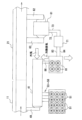
図1は塗装設備用空調システム31を説明するための概略図であり、図2は塗装設備のレイアウトを示す概略平面図である。本実施形態の塗装設備は、塗装ブース11、乾燥炉21、塗装設備用空調システム31(ブース用空調機41、空調機用ヒートポンプ51、熱交換器61、貯湯タンク71、乾燥炉用ヒートポンプ81)を備えている。
FIG. 1 is a schematic diagram for explaining an
図2に示されるように、本実施形態の塗装設備を構成する塗装ブース11及び乾燥炉21は、被塗物(例えば自動車ボディなど)を搬送する1つの搬送ライン上に配置されている。この搬送ラインにおいて、塗装ブース11が上流側に配置され、乾燥炉21が下流側に配置されている。
As shown in FIG. 2, the
塗装ブース11が設けられているエリアは、搬送ラインにおいて被塗物に塗料を塗布するためエリアとなっている。塗装ブース11は、塗装室と、塗装室の上側に設けられ塗装室にダウンフロー(上方から下方に向かう一定方向)の空気を供給するための給気室と、塗装室の下側に設けられその塗装室内の空気を排気するための排気室とを備えている。本実施形態の塗装ブース11では、ブース用空調機41から排出される空調空気が給気室からダウンフローで塗装室内に供給される。
The area where the
塗装ブース11の塗装室では、図示しない塗装機から塗料ミストを噴射することで被塗物の塗装が行われる。このとき、塗装機からオーバースプレーされて飛散した塗料ミストは、塗装室内に作用するダウンフローの空調空気によって塗装室から排気室に排出される。排気室では、乾式フィルターを使用して空気中に含まれる塗料ミストが捕捉され塗料が回収される。また、排気室から排出される空気は、送風ファンによって大気に放出される。
In the coating room of the
乾燥炉21が設けられているエリアは、塗装ブース11を通過した被塗物上の塗料を乾燥するためのエリアとなっている。この乾燥炉21は、通常、被塗物をコンベアで搬送しながらその塗膜を乾燥硬化させるために、炉本体の両端に出入口を設けたトンネル状に形成されている(図1参照)。乾燥炉21の内部には、例えば炉の長手方向に沿って複数の乾燥ゾーンが連続して設けられている。そして、各乾燥ゾーンには、炉内に熱風を吹き出す熱風給気口と、炉内から熱風を排出する排気口とがそれぞれ設けられている。従って、被塗物が乾燥炉21を通過する際に、熱風給気口から吹き出される熱風に晒されることで、被塗物上の塗料が乾燥されるようになっている。
The area where the drying
図1に示されるように、ブース用空調機41は、装置外部から取り入れた空気を所定温度(例えば23℃前後)及び所定湿度(例えば70%RH前後)に調節して塗装ブース11へ送気するための装置である。本実施形態のブース用空調機41は、搬送ラインにおける塗装ブース11のすぐ脇に隣接した状態で、塗装ブース11に平行に配置されている。このブース用空調機41は、プレヒータ42、ワッシャ43、クーリングコイル44、レヒータ45及び送風ファン46を備えている。なお、ブース用空調機41の出口側と塗装ブース11との間は、空調空気移送経路49を介して流路的に接続されている。
As shown in FIG. 1, the
プレヒータ42は、取り込んだ空気の温度を調整する調温手段の一種であって、空気を加熱して温度を上げる加熱手段である。ワッシャ43は、取り込んだ空気の湿度を調整する調湿手段の一種であって、プレヒータ42を経た空気に対する水の噴射により空気の湿度を上げる加湿手段である。クーリングコイル44は、取り込んだ空気の温度を調整する調温手段の一種であって、ワッシャ43を経た空気を冷却して温度を下げる冷却手段である。レヒータ45は、取り込んだ空気の温度を調整する調温手段の一種であって、クーリングコイル44を経た空気を加熱して温度を上げる加熱手段である。送風ファン46は、調温及び調湿された空気(即ち空調空気)を塗装ブース11に圧送するための手段である。
The
図2に示されるように、空調機用ヒートポンプ51はいわゆる間接温調式のヒートポンプであって、ブース用空調機41の近くに隣接して複数配置されている。なお、ブース用空調機41は、複数の空調機用ヒートポンプ51からなるヒートポンプ群と塗装ブース11との間に位置している。
As shown in FIG. 2, the air
図1に示されるように、空調機用ヒートポンプ51は、熱媒体としての冷媒が流れる冷媒流路52を有している。冷媒流路52は環状をなす閉じられた流路であり、冷媒流路52上には、凝縮器(放熱部)、蒸発器(吸熱部)、コンプレッサ及び膨張弁が設置されている。凝縮器は、冷媒流路52と温風供給経路53との間で熱を交換する機器である。冷媒流路52内を流れる冷媒の熱は、温風供給経路53内を流れる循環水に伝達され、温水を生成するようになっている。この温水は、温水供給経路53を介してプレヒータ42及びレヒータ45に供給される。なお、プレヒータ42及びレヒータ45を経て温度が下がった循環水は、温水戻り経路54を介して空調機用ヒートポンプ51に戻され、再び加熱される。一方、冷媒流路52内を流れる冷媒の冷熱は、冷風供給経路55内を流れる循環水に伝達され、冷水を生成するようになっている。この冷水は、冷水供給経路55を介してクーリングコイル44に供給される。なお、クーリングコイル44を経て温度が上がった冷水は、冷水戻り経路56を介して空調機用ヒートポンプ51に戻され、再び冷却される。なお、空調機用ヒートポンプ51は、温水及び冷水の切替によって、どちらかを供給することができる。循環水を温水供給経路及び冷水供給経路のどちらに流すかの切替は、図示しないバルブによって行われる。
As shown in FIG. 1, the air
図1に示されるように、本実施形態では、熱交換器61、貯湯タンク71及び乾燥炉用ヒートポンプ81によって排気再加熱手段が構成されている。排気再加熱手段を構成する乾燥炉用ヒートポンプ81(熱分離手段)は、取り込んだ外気から熱を分離して冷熱を排出する。この乾燥炉用ヒートポンプ81も間接温調式のヒートポンプであって、ブース用空調機41の給気側端の近くに隣接して複数配置されている。
As shown in FIG. 1, in this embodiment, a
乾燥炉用ヒートポンプ81は、熱媒体としての冷媒が流れる冷媒流路82を有している。冷媒流路82は環状をなす閉じられた流路であり、冷媒流路82上には、凝縮器(放熱部)、蒸発器(吸熱部)、コンプレッサ及び膨張弁が設置されている。凝縮器は、冷媒流路82と高温水供給経路83との間で熱を交換する機器である。冷媒流路82内を流れる冷媒の熱は、高温水供給経路83内を流れる循環水に伝達され、高温水を生成するようになっている。この高温水は、高温水供給経路83を介して貯湯タンク71に供給され、貯湯タンク71内の水を加熱して湯にする。つまり、この貯湯タンク71は、加熱された水温の変化を緩和するためのウォーターダンパーとして機能する。なお、貯湯タンク71を経て温度が下がった高温水は、高温水戻り経路84を介して乾燥炉用ヒートポンプ81に戻され、再び加熱される。
The drying
一方、冷媒流路82内を流れる冷媒の冷熱は、冷熱排気となって、冷熱移送経路86を介して乾燥炉用ヒートポンプ81の外部に排出される(図2参照)。この冷熱移送経路86は、ブース用空調機41の給気側に流路的に接続されている。冷熱移送経路86の終端には、図示しない冷熱排気取込用ダンパーが設けられている。この冷熱排気取込用ダンパーの開度を調整することにより、ブース用空調機41への冷熱排気の取込量が調整可能となっている。また、ブース用空調機41の給気側には、図示しない外気取込用ダンパーが設けられている。この外気取込用ダンパーの開度を調整することにより、外気の取込量が調整可能となっている。
On the other hand, the cold heat of the refrigerant flowing in the
熱交換器61は、搬送ラインにおける乾燥炉21のすぐ脇に隣接し、かつブース用空調機41の給気側端の近くに隣接して配置されている。熱交換器61の一次側と乾燥炉21との間は、排気経路62を介して流路的に接続されている。熱交換器61の二次側と乾燥炉21との間は、戻し経路63を介して流路的に接続されている。戻し経路63上には送風ファン64が設けられている。また、熱交換器61と貯湯タンク71の高温側との間は、湯供給経路72を介して流路的に接続されている。熱交換器61と貯湯タンク71の低温側との間は、湯戻し経路73を介して流路的に接続されている。従って、乾燥炉21から熱交換器61に供給された排気は、加熱された後に乾燥炉21に戻されて再利用されるようになっている。つまり、本実施形態の排気再加熱手段は、熱分離手段により分離した熱で乾燥炉21からの排気を加熱して乾燥炉21に戻す役割を果たしている。なお、貯湯タンク71は、ブース用空調機41の給気側端の近くにおいて、乾燥炉用ヒートポンプ81と熱交換器61との間に配置されている。
The
この塗装設備用空調システム31では、いくつかの箇所にセンシング手段が設けられている。具体的にいうと、ブース用空調機41は、空調機入口側温湿度センサS1、空調機出口側温湿度センサS2、空調機内温度センサS3も備えている。空調機入口側温湿度センサS1は、ブース用空調機41における外気の取り込み口付近に配置されている。空調機出口側温湿度センサS2は、空調空気が送り出される送風ファン46の出口側に配置されている。空調機内温度センサS3は、ワッシャ43の上流側に配置されている。また、ブース用空調機41の外部には、外気温湿度センサS4が設けられている。各々の空調機用ヒートポンプ51の近傍における温水供給経路53上には温水供給経路用温度センサS5が配置され、冷水供給経路55上には冷水供給経路用温度センサS6が配置されている。また、乾燥炉用ヒートポンプ81における高温水供給経路83上には、高温水供給経路用温度センサS7が配置され、高温水戻り経路84上には高温水戻り経路用温度センサS8が配置されている。また、熱交換器61の二次側には熱交換器二次側温度センサS9が配置されている。また、冷熱移送経路86上には、冷熱排気温湿度センサS10が設けられている。
This painting equipment
この塗装設備用空調システム31は、CPUや記憶手段91e(ROM、RAM)等からなる周知のコンピュータにより構成された制御装置91(空調機制御手段)を備えている。図3のブロック図に示されるように、この制御装置91は、算出手段91a、第1比較手段91b、第2比較手段91c、空調空気選択手段91dをさらに備えている。この制御装置91には、図示しない各々のドライバ回路を介して制御対象(即ち、プレヒータ42、ワッシャ43、クーリングコイル44、レヒータ45及び送風ファン46)が電気的に接続されている。また、この制御装置91には、上記各センサS1~S10が電気的に接続されている。このように構成された制御装置91では、各センサS1~S10から出力される温度や湿度の測定結果に基づいて、ブース用空調機41における前記制御対象が可変制御される。その結果、所定の温度や湿度に調整された空調空気が生成されるようになっている。
This
次に、制御装置91が行う温湿度制御について説明する。制御装置91を構成する記憶手段91e内には、温湿度制御のためのプログラムが格納されており、CPUは当該プログラムを記憶手段91eから読み出して順次実行するようになっている。記憶手段91e内には、このプログラムのほかに、空気の状態値を座標に表した湿り空気線図101に関するデータ(湿り空気線図テーブル)が格納されている。ちなみに、エンタルピーは湿り空気線図101の右上に行くほど高くなり、逆に左下にいくほど低くなる。
Next, temperature and humidity control performed by the
空調機制御手段である制御装置91は、熱分離手段である乾燥炉用ヒートポンプ81が発生する冷熱排気の温湿度と、外気の温湿度との比較を行う。そして制御装置は、その結果に基づき、冷熱排気及び外気の少なくとも一方を空調空気としてブース用空調機41に給気することにより、ブース用空調機41への給気温湿度を設定温湿度に近づける制御を行う。以下、この制御について詳細に説明する。
The
ここで、図4、図5の湿り空気線図101上の点P1は、空調空気の温湿度のその時点においての理想状態点(即ち制御目標点)を示しており、この点P1における温湿度が設定温湿度として定義される。図4の湿り空気線図101において、点P2は乾燥炉用ヒートポンプ81が排出する冷熱排気の状態点P2を示し、P3は外気の状態点P3を示している。なお、冷熱排気のエンタルピーはE2、外気のエンタルピーはE3で表されている。湿り空気線図101上においては、設定温湿度のエンタルピーE1を中心値とする所定幅の範囲があらかじめ設定されている。この範囲の上限値はE1max、下限値はE1minで表されている。当該所定幅の範囲は特に限定されないが、本実施形態では±5(kJ/kg(DA))に設定されている。従って、例えば設定温湿度のエンタルピーE1が60であれば、当該所定幅が10となり、上限値E1maxが55、下限値E1minが65となる。
Here, point P1 on the hygrodynamic diagram 101 in FIGS. 4 and 5 indicates the ideal state point (i.e., control target point) of the temperature and humidity of the conditioned air at that point, and the temperature and humidity at this point P1 is defined as the set temperature and humidity. In the humid air diagram 101 of FIG. 4, point P2 indicates the state point P2 of the cold and hot exhaust discharged by the drying
制御装置91における算出手段91a(即ちCPU)は、上記各センサS1~S10で得た設定温湿度情報、外気の温湿度情報及び冷熱排気の温湿度情報に基づいて、設定温湿度のエンタルピーE1、外気のエンタルピーE3及び冷熱排気のエンタルピーE2を算出する。
The calculation means 91a (i.e., CPU) in the
次に制御装置91における第1比較手段91b(即ちCPU)は、算出した上記3つのエンタルピーE1、E2、E3に基づいて、設定温湿度と外気とのエンタルピー差ΔE13及び設定温湿度と冷熱排気とのエンタルピー差ΔE12を算出しかつ、それら同士を比較する。併せて、制御装置91における第2比較手段91c(即ちCPU)は、設定温湿度のエンタルピーE1を中心値としてあらかじめ設定された所定範囲の上限値E1max及び下限値E1minと、外気のエンタルピーE3及び冷熱排気のエンタルピーE2とを比較する。そして、外気のエンタルピーE3及び冷熱排気のエンタルピーE2の両方が所定範囲内に属しているか否かが判定される。
Next, the first comparison means 91b (i.e., CPU) in the
例えば図4に示す状態では、外気のエンタルピーE3及び冷熱排気のエンタルピーE2がどちらも所定範囲内に属しておらず、かつ、外気のエンタルピーE3のほうが冷熱排気のエンタルピーE2よりも大きい値となっている。つまり、設定温湿度と冷熱排気とのエンタルピー差ΔE12のほうが、設定温湿度と外気とのエンタルピー差ΔE13よりも小さくなっている。この場合、制御装置91における空調空気選択手段91d(即ちCPU)は、設定温湿度に近づけるのに要するエネルギーが少ないほうの熱媒体、即ち乾燥炉用ヒートポンプ81が排出する冷熱排気を空調空気として選択する。このとき制御装置91のCPUは、冷熱排気取込用ダンパーを開けて外気取込用ダンパーを閉じる制御を行い、冷熱排気をブース用空調機41に取り込んで、空調空気とする。ちなみに、設備内の外気が高温多湿になる夏季には、このような状態になりやすい。
For example, in the state shown in FIG. 4, the enthalpy E3 of outside air and the enthalpy E2 of cold exhaust air are both outside the predetermined range, and the enthalpy E3 of outside air is larger than the enthalpy E2 of cold exhaust air. There is. In other words, the enthalpy difference ΔE12 between the set temperature and humidity and the cold exhaust gas is smaller than the enthalpy difference ΔE13 between the set temperature and humidity and the outside air. In this case, the conditioned air selection means 91d (i.e., CPU) in the
また、特に図示はしないが、外気のエンタルピーE3及び冷熱排気のエンタルピーE2がどちらも所定範囲内に属しておらず、かつ、冷熱排気のエンタルピーE2のほうが外気のエンタルピーE3よりも大きい値となった状態について考える。この場合、設定温湿度と外気とのエンタルピー差ΔE13のほうが、設定温湿度と冷熱排気とのエンタルピー差ΔE12よりも小さくなる。この場合、空調空気選択手段91dは、設定温湿度に近づけるのに要するエネルギーが少ないほうの熱媒体、即ち外気を空調空気として選択する。このとき制御装置91のCPUは、冷熱排気取込用ダンパーを閉じて外気取込用ダンパーを開く制御を行い、外気をブース用空調機41に取り込んで、空調空気とする。
Further, although not shown in the figure, neither the enthalpy E3 of the outside air nor the enthalpy E2 of the cold exhaust air falls within the predetermined range, and the enthalpy E2 of the cold exhaust air has a larger value than the enthalpy E3 of the outside air. Think about the state. In this case, the enthalpy difference ΔE13 between the set temperature and humidity and the outside air is smaller than the enthalpy difference ΔE12 between the set temperature and humidity and the cold exhaust gas. In this case, the conditioned air selection means 91d selects the heat medium that requires less energy to bring the temperature and humidity close to the set temperature and humidity, that is, the outside air, as the conditioned air. At this time, the CPU of the
また、図5に示す状態では、外気のエンタルピーE3及び冷熱排気のエンタルピーE2が両方とも所定範囲内に属しており、しかも設定温湿度のエンタルピーE1との差が比較的小さい。この場合、空調空気選択手段91dは、外気及び冷熱排気の両方を空調空気として選択する。このとき制御装置91のCPUは、冷熱排気取込用ダンパー及び外気取込用ダンパーの両方を開く制御を行い、外気及び冷熱排気の混合気体をブース用空調機41に取り込んで、空調空気とする。なお、冷熱排気取込用ダンパー及び外気取込用ダンパーの開度は特に限定されず任意に設定されるが、ここでは開度を等しく設定している。
Further, in the state shown in FIG. 5, the enthalpy E3 of the outside air and the enthalpy E2 of the cold exhaust gas both belong to the predetermined range, and the difference from the enthalpy E1 of the set temperature and humidity is relatively small. In this case, the conditioned air selection means 91d selects both the outside air and the cold exhaust air as the conditioned air. At this time, the CPU of the
空調空気として用いる熱媒体の選択を行った後、制御装置91のCPUは、温湿度を設定温湿度(即ち湿り空気線図101上の制御目標点P1)に到達させるために、例えば従来公知のPID制御により各制御対象を制御する。以上の制御の結果、塗装ブース11に供給するのに適した空調空気が生成されるようになっている。
After selecting the heat medium to be used as the conditioned air, the CPU of the
従って、本実施の形態によれば以下の効果を得ることができる。 Therefore, according to this embodiment, the following effects can be obtained.
(1)本実施形態の塗装設備用空調システム31では、排気再加熱手段の熱分離手段(乾燥炉用ヒートポンプ81)により分離した熱及び冷熱のうち、熱は乾燥炉21からの排気の加熱を通じて乾燥炉21の再加熱に利用される。その一方で、吸熱後に熱分離手段で発生する冷熱は、乾燥炉21では利用されずに排出される。この冷熱排気の温湿度は外気の温湿度と比較され、所定の条件を満たす場合には、その冷熱排気の少なくとも一部が空調空気としてブース用空調機41に給気される。つまり、乾燥炉21で利用されずに廃棄されていた冷熱排気が、ブース用空調機41を経て塗装ブース11の空調空気として有効利用される。このため、空調に要するエネルギー消費量を低減することが可能となる。
(1) In the
(2)本実施形態の塗装設備用空調システム31では、算出手段91aが、設定温湿度のエンタルピーE1、外気のエンタルピーE3及び冷熱排気のエンタルピーE2を算出する。この算出結果に基づき、第1比較手段91bが、設定温湿度と外気とのエンタルピー差ΔE13及び設定温湿度と冷熱排気とのエンタルピー差ΔE12を算出しかつ比較する。この比較結果に基づいて、空調空気選択手段91dが、外気及び冷熱排気のうち設定温湿度とのエンタルピー差が小さいほう、つまり設定温湿度に近づけるのに要するエネルギーが少ないほうを空調空気として選択する。その結果、空調に要するエネルギー消費量を低減することが可能となる。
(2) In the
(3)本実施形態の塗装設備用空調システム31では、第2比較手段91cによって、外気のエンタルピーE3及び冷熱排気のエンタルピーE2の両方が所定範囲内に属しているか否かが判定される。そして、外気のエンタルピーE2及び冷熱排気のエンタルピーE3と設定温湿度のエンタルピーE1との差が比較的小さい場合には、外気及び冷熱排気の両方が空調空気として選択される。この場合、外気及び冷熱排気の小さな変動に対するダンパーの頻繁な切替が抑制されるため、安定した設定温湿度調整を行うことができる。
(3) In the
(4)本実施形態の塗装設備用空調システム31では、図2に示されるように、排気再加熱手段を構成する各機器(乾燥炉用ヒートポンプ81等)が、いずれもブース用空調機41の給気側端の近くに隣接して配置されている。そのため、乾燥炉用ヒートポンプ81から排出される冷熱排気を短い距離で効率よくブース用空調機41に供給することができる。このことは、空調に要するエネルギー消費量の低減に有利に作用する。
(4) In the painting equipment
なお、本発明の各実施の形態は以下のように変更してもよい。 Note that each embodiment of the present invention may be modified as follows.
・上記実施形態では、空調機用ヒートポンプ51として間接温調式のヒートポンプを用いて塗装設備用空調システム31を構成したが、これに限定されない。例えば、図6に示す別の実施形態の塗装設備用空調システム31Aでは、直膨式のヒートポンプH1を用いてシステムを構成している。この直膨式のヒートポンプH1は、熱媒体としての冷媒が流れる環状の冷媒流路111上に、放熱部112、吸熱部113、コンプレッサ114及び膨張弁115を備えている。熱交換器の役割を果たす放熱部112と乾燥炉21との間は、排気経路117を介して流路的に接続されている。熱交換器116の二次側と乾燥炉21との間は、戻し経路118を介して流路的に接続されている。戻し経路118上には送風ファン119が設けられている。また、熱交換器の役割を果たす吸熱部113で発生した冷熱は、冷熱排気となって排出されるとともに、ブース用空調機41の給気側に供給されるようになっている。なお、直膨式のヒートポンプH1を用いたシステムでは、放熱部112及び吸熱部113が熱交換器の役割を果たすため、熱移動するのに別途熱交換器を設置する必要がない。ゆえに、効率の良い熱移動を実現することができる。
- In the above embodiment, the painting equipment
・上記実施形態では、外気のエンタルピーE3及び冷熱排気のエンタルピーE2の両方が所定範囲内に属している場合に外気及び冷熱排気の両方を空調空気として選択する際に、両者の混合比率を等しくしたが、これに限定されない。例えば、いずれか一方を他方よりも多くしてもよい。また、この混合比率を可変としてもよい。 - In the above embodiment, when both the outside air and the cold exhaust air are selected as conditioned air when the enthalpy E3 of the outside air and the enthalpy E2 of the cold exhaust air are both within a predetermined range, the mixing ratio of the two is made equal. However, it is not limited to this. For example, one may be greater than the other. Further, this mixing ratio may be made variable.
11…塗装ブース
21…乾燥炉
31…塗装設備用空調システム
41…ブース用空調機
81、H1…熱分離手段としてのヒートポンプ
91…空調機制御手段としての制御装置
91a…算出手段
91b…第1比較手段
91c…第2比較手段
91d…空調空気選択手段
E1…設定温湿度のエンタルピー
E2…冷熱排気のエンタルピー
E3…外気のエンタルピー
ΔE12、ΔE13…エンタルピー差
E1max…上限値
E1min…下限値
11...
Claims (3)
外気を給気しその温湿度を調節して前記塗装ブースへ送気するブース用空調機と、
取り込んだ外気から熱を分離して冷熱を排出する熱分離手段を含んで構成され、前記熱分離手段により分離した熱で前記乾燥炉からの排気を加熱して前記乾燥炉に戻す排気再加熱手段と、
前記熱分離手段で発生する冷熱排気の温湿度と、前記外気の温湿度との比較結果に基づき、前記冷熱排気及び前記外気の少なくとも一方を空調空気として前記ブース用空調機に給気することにより、前記ブース用空調機への給気温湿度を設定温湿度に近づける制御を行う空調機制御手段と
を備え、
前記空調機制御手段は、
設定温湿度情報、前記外気の温湿度情報及び前記冷熱排気の温湿度情報に基づいて、前記設定温湿度のエンタルピー、前記外気のエンタルピー及び前記冷熱排気のエンタルピーを算出する算出手段と、
前記設定温湿度のエンタルピーと、前記算出手段が算出した前記外気のエンタルピー及び前記冷熱排気のエンタルピーとに基づいて、前記設定温湿度と前記外気とのエンタルピー差及び前記設定温湿度と前記冷熱排気とのエンタルピー差を算出しかつ比較する第1比較手段と、
前記設定温湿度のエンタルピーを中心値としてあらかじめ設定された所定範囲の上限値及び下限値と、前記外気のエンタルピー及び前記冷熱排気のエンタルピーとを比較し、前記外気のエンタルピー及び前記冷熱排気のエンタルピーの両方が前記所定範囲内に属しているか否かを判定する第2比較手段と、
前記外気及び前記冷熱排気の少なくとも一方を前記空調空気として選択する空調空気選択手段と、を含み、
前記空調空気選択手段は、
前記外気のエンタルピー及び前記冷熱排気のエンタルピーの両方が前記所定範囲内に属しているという条件を満たしている場合には、前記外気及び前記冷熱排気の両方を前記空調空気として選択し、
前記条件を満たしておらず、かつ、前記設定温湿度と前記外気とのエンタルピー差のほうが小さい場合には、前記外気を前記空調空気として選択し、
前記条件を満たしておらず、かつ、前記設定温湿度と前記冷熱排気とのエンタルピー差のほうが小さい場合には、前記冷熱排気を前記空調空気として選択する
ことを特徴とする塗装設備用空調システム。 An air conditioning system in a painting facility comprising a coating booth that applies paint to an object to be coated, and a drying oven that dries the paint on the object that has passed through the coating booth,
a booth air conditioner that supplies outside air, adjusts its temperature and humidity, and sends the air to the painting booth;
Exhaust gas reheating means includes a heat separation means for separating heat from the taken in outside air and discharging cold heat, and heats the exhaust gas from the drying furnace with the heat separated by the heat separation means and returns it to the drying furnace. and,
By supplying at least one of the cold exhaust gas and the outside air to the booth air conditioner as conditioned air based on a comparison result between the temperature and humidity of the cold exhaust gas generated by the thermal separation means and the temperature and humidity of the outside air. , an air conditioner control means for controlling the temperature and humidity supplied to the booth air conditioner to approach the set temperature and humidity ,
The air conditioner control means includes:
Calculation means for calculating the enthalpy of the set temperature and humidity, the enthalpy of the outside air, and the enthalpy of the cold heat exhaust based on the set temperature and humidity information, the temperature and humidity information of the outside air, and the temperature and humidity information of the cold heat exhaust;
Based on the enthalpy of the set temperature and humidity, the enthalpy of the outside air and the enthalpy of the cold exhaust air calculated by the calculating means, calculate the enthalpy difference between the set temperature and humidity and the outside air, and the difference between the set temperature and humidity and the cold exhaust air. a first comparison means for calculating and comparing the enthalpy difference of;
The enthalpy of the outside air and the enthalpy of the cold exhaust are compared with the upper and lower limits of a predetermined range set in advance with the enthalpy of the set temperature and humidity as the center value, and the enthalpy of the outside air and the enthalpy of the cold exhaust are determined. a second comparing means for determining whether both belong to the predetermined range;
conditioned air selection means for selecting at least one of the outside air and the cold exhaust air as the conditioned air;
The air conditioning air selection means includes:
If the condition that both the enthalpy of the outside air and the enthalpy of the cold exhaust air belong to the predetermined range is satisfied, both the outside air and the cold exhaust air are selected as the conditioned air,
If the conditions are not met and the enthalpy difference between the set temperature and humidity and the outside air is smaller, the outside air is selected as the conditioned air;
If the above conditions are not met and the enthalpy difference between the set temperature and humidity and the cold exhaust air is smaller, the cold exhaust air is selected as the conditioned air.
An air conditioning system for painting equipment that is characterized by:
前記冷熱移送経路の終端に設けられ、開度調整により前記ブース用空調機への前記冷熱排気の取込量を調整可能とする冷熱排気取込用ダンパーと、 a damper for cold exhaust gas intake, which is provided at the end of the cold heat transfer path and is capable of adjusting the amount of cold exhaust gas taken into the booth air conditioner by adjusting the opening degree;
前記ブース用空調機の給気側に設けられ、開度調整により外気の取込量を調整可能とする外気取込用ダンパーと an outside air intake damper that is installed on the air supply side of the booth air conditioner and that allows the amount of outside air intake to be adjusted by adjusting the opening degree;
を備えたことを特徴とする請求項1に記載の塗装設備用空調システム。The air conditioning system for painting equipment according to claim 1, further comprising:
前記条件を満たしている場合には、前記冷熱排気取込用ダンパー及び前記外気取込用ダンパーの両方を開く制御を行い、 If the conditions are met, control is performed to open both the cold and hot exhaust intake damper and the outside air intake damper,
前記条件を満たしておらず、かつ、前記設定温湿度と前記外気とのエンタルピー差のほうが小さい場合には、前記冷熱排気取込用ダンパーを閉じて前記外気取込用ダンパーを開く制御を行い、 If the conditions are not met and the enthalpy difference between the set temperature and humidity and the outside air is smaller, control is performed to close the cold and hot exhaust intake damper and open the outside air intake damper,
前記条件を満たしておらず、かつ、前記設定温湿度と前記冷熱排気とのエンタルピー差のほうが小さい場合には、前記冷熱排気取込用ダンパーを開けて前記外気取込用ダンパーを閉じる制御を行う If the conditions are not met and the enthalpy difference between the set temperature and humidity and the cold exhaust gas is smaller, control is performed to open the cold exhaust air intake damper and close the outside air intake damper.
ことを特徴とする請求項2に記載の塗装設備用空調システム。The air conditioning system for painting equipment according to claim 2.
Priority Applications (2)
| Application Number | Priority Date | Filing Date | Title |
|---|---|---|---|
| JP2022013776A JP7379552B2 (en) | 2022-01-31 | 2022-01-31 | Air conditioning system for painting equipment |
| PCT/JP2022/046595 WO2023145299A1 (en) | 2022-01-31 | 2022-12-19 | Air-conditioning system for coating facility |
Applications Claiming Priority (1)
| Application Number | Priority Date | Filing Date | Title |
|---|---|---|---|
| JP2022013776A JP7379552B2 (en) | 2022-01-31 | 2022-01-31 | Air conditioning system for painting equipment |
Publications (2)
| Publication Number | Publication Date |
|---|---|
| JP2023111762A JP2023111762A (en) | 2023-08-10 |
| JP7379552B2 true JP7379552B2 (en) | 2023-11-14 |
Family
ID=87471559
Family Applications (1)
| Application Number | Title | Priority Date | Filing Date |
|---|---|---|---|
| JP2022013776A Active JP7379552B2 (en) | 2022-01-31 | 2022-01-31 | Air conditioning system for painting equipment |
Country Status (2)
| Country | Link |
|---|---|
| JP (1) | JP7379552B2 (en) |
| WO (1) | WO2023145299A1 (en) |
Citations (4)
| Publication number | Priority date | Publication date | Assignee | Title |
|---|---|---|---|---|
| JP2006343019A (en) | 2005-06-08 | 2006-12-21 | Sanden Corp | Refrigeration air conditioning system |
| JP2007198655A (en) | 2006-01-25 | 2007-08-09 | Denso Corp | Air conditioning system |
| JP2009291762A (en) | 2008-06-09 | 2009-12-17 | Panasonic Corp | Painting apparatus |
| JP2016022402A (en) | 2014-07-16 | 2016-02-08 | 株式会社前川製作所 | Painting system and operational method of painting system |
-
2022
- 2022-01-31 JP JP2022013776A patent/JP7379552B2/en active Active
- 2022-12-19 WO PCT/JP2022/046595 patent/WO2023145299A1/en not_active Ceased
Patent Citations (4)
| Publication number | Priority date | Publication date | Assignee | Title |
|---|---|---|---|---|
| JP2006343019A (en) | 2005-06-08 | 2006-12-21 | Sanden Corp | Refrigeration air conditioning system |
| JP2007198655A (en) | 2006-01-25 | 2007-08-09 | Denso Corp | Air conditioning system |
| JP2009291762A (en) | 2008-06-09 | 2009-12-17 | Panasonic Corp | Painting apparatus |
| JP2016022402A (en) | 2014-07-16 | 2016-02-08 | 株式会社前川製作所 | Painting system and operational method of painting system |
Also Published As
| Publication number | Publication date |
|---|---|
| WO2023145299A1 (en) | 2023-08-03 |
| JP2023111762A (en) | 2023-08-10 |
Similar Documents
| Publication | Publication Date | Title |
|---|---|---|
| US4367787A (en) | Air conditioning apparatus and method for paint spray booths | |
| US4494596A (en) | Method and apparatus for conditioning air temperature and humidity | |
| CA2633185C (en) | Intelligent air conditioning system for a paint booth | |
| JP4555097B2 (en) | Clean room air conditioner | |
| JP5351707B2 (en) | Painting equipment | |
| CN104056765A (en) | Device for drying a workpiece and method for operating such a device | |
| CN105121970A (en) | Method for the conditioning of air, and air-conditioning system | |
| JP4960292B2 (en) | Temperature and humidity control device | |
| JP7151680B2 (en) | painting system | |
| JP2020041796A (en) | Air conditioner with dehumidifying function and control method thereof | |
| JP7379552B2 (en) | Air conditioning system for painting equipment | |
| KR20160084909A (en) | Cooling tower for plume abatment | |
| JP5464841B2 (en) | Paint booth exhaust recycling air conditioning system | |
| JPH07174360A (en) | Operating method of air conditioner | |
| JPH05288390A (en) | Outdoor air conditioner | |
| JP3429141B2 (en) | Air conditioner | |
| RU2117228C1 (en) | Method of automatic control of drying process | |
| JP7580229B2 (en) | Air Conditioning System | |
| JPS60228690A (en) | Controlling method of steel plate drying apparatus | |
| JP5642982B2 (en) | Drying equipment | |
| JP2025017413A (en) | Paint booth air conditioning system | |
| JP7735209B2 (en) | Air conditioning system | |
| JP4278239B2 (en) | Watering type air conditioner | |
| JP3122713B2 (en) | Air conditioning system | |
| JP3193695B2 (en) | Watering type air conditioner |
Legal Events
| Date | Code | Title | Description |
|---|---|---|---|
| A621 | Written request for application examination |
Free format text: JAPANESE INTERMEDIATE CODE: A621 Effective date: 20230525 |
|
| A871 | Explanation of circumstances concerning accelerated examination |
Free format text: JAPANESE INTERMEDIATE CODE: A871 Effective date: 20230525 |
|
| A131 | Notification of reasons for refusal |
Free format text: JAPANESE INTERMEDIATE CODE: A131 Effective date: 20230711 |
|
| A521 | Request for written amendment filed |
Free format text: JAPANESE INTERMEDIATE CODE: A523 Effective date: 20230824 |
|
| TRDD | Decision of grant or rejection written | ||
| A01 | Written decision to grant a patent or to grant a registration (utility model) |
Free format text: JAPANESE INTERMEDIATE CODE: A01 Effective date: 20231024 |
|
| A61 | First payment of annual fees (during grant procedure) |
Free format text: JAPANESE INTERMEDIATE CODE: A61 Effective date: 20231101 |
|
| R150 | Certificate of patent or registration of utility model |
Ref document number: 7379552 Country of ref document: JP Free format text: JAPANESE INTERMEDIATE CODE: R150 |