JP4741908B2 - Information processing apparatus and information processing method - Google Patents
Information processing apparatus and information processing method Download PDFInfo
- Publication number
- JP4741908B2 JP4741908B2 JP2005261126A JP2005261126A JP4741908B2 JP 4741908 B2 JP4741908 B2 JP 4741908B2 JP 2005261126 A JP2005261126 A JP 2005261126A JP 2005261126 A JP2005261126 A JP 2005261126A JP 4741908 B2 JP4741908 B2 JP 4741908B2
- Authority
- JP
- Japan
- Prior art keywords
- gui component
- display
- gui
- unit
- document
- Prior art date
- Legal status (The legal status is an assumption and is not a legal conclusion. Google has not performed a legal analysis and makes no representation as to the accuracy of the status listed.)
- Expired - Fee Related
Links
Images


Classifications
-
- G—PHYSICS
- G06—COMPUTING OR CALCULATING; COUNTING
- G06F—ELECTRIC DIGITAL DATA PROCESSING
- G06F9/00—Arrangements for program control, e.g. control units
- G06F9/06—Arrangements for program control, e.g. control units using stored programs, i.e. using an internal store of processing equipment to receive or retain programs
- G06F9/44—Arrangements for executing specific programs
- G06F9/451—Execution arrangements for user interfaces
-
- G—PHYSICS
- G06—COMPUTING OR CALCULATING; COUNTING
- G06F—ELECTRIC DIGITAL DATA PROCESSING
- G06F3/00—Input arrangements for transferring data to be processed into a form capable of being handled by the computer; Output arrangements for transferring data from processing unit to output unit, e.g. interface arrangements
- G06F3/01—Input arrangements or combined input and output arrangements for interaction between user and computer
- G06F3/048—Interaction techniques based on graphical user interfaces [GUI]
- G06F3/0487—Interaction techniques based on graphical user interfaces [GUI] using specific features provided by the input device, e.g. functions controlled by the rotation of a mouse with dual sensing arrangements, or of the nature of the input device, e.g. tap gestures based on pressure sensed by a digitiser
- G06F3/0488—Interaction techniques based on graphical user interfaces [GUI] using specific features provided by the input device, e.g. functions controlled by the rotation of a mouse with dual sensing arrangements, or of the nature of the input device, e.g. tap gestures based on pressure sensed by a digitiser using a touch-screen or digitiser, e.g. input of commands through traced gestures
- G06F3/04883—Interaction techniques based on graphical user interfaces [GUI] using specific features provided by the input device, e.g. functions controlled by the rotation of a mouse with dual sensing arrangements, or of the nature of the input device, e.g. tap gestures based on pressure sensed by a digitiser using a touch-screen or digitiser, e.g. input of commands through traced gestures for inputting data by handwriting, e.g. gesture or text
Landscapes
- Engineering & Computer Science (AREA)
- Theoretical Computer Science (AREA)
- Software Systems (AREA)
- General Engineering & Computer Science (AREA)
- Human Computer Interaction (AREA)
- Physics & Mathematics (AREA)
- General Physics & Mathematics (AREA)
- User Interface Of Digital Computer (AREA)
Description
本発明は、情報処理装置及び情報処理方法に関する。 The present invention relates to an information processing apparatus及beauty information processing method.
従来、デジタイザ付きのPC(Personal Computer)、PDA(Personal Digital Assistance)、大画面ディスプレイ等、手書き入力手段を備えた情報処理装置が存在する。このような情報処理装置では、画面上に表示されたグラフィカルユーザインターフェース(GUI:Graphical User Interface)をキーボードやマウスを用いて操作することが一般的に行われている。また、このような情報処理装置では、GUIに対して手書き入力によるコマンド実行の指示操作が可能な機能を有するものがある。このような情報処理装置は会議システム等で用いられている。 2. Description of the Related Art Conventionally, there is an information processing apparatus including handwritten input means such as a PC (Personal Computer) with a digitizer, a PDA (Personal Digital Assistance), and a large screen display. In such an information processing apparatus, a graphical user interface (GUI) displayed on a screen is generally operated using a keyboard or a mouse. Some of such information processing apparatuses have a function that allows a command execution instruction operation by handwriting input to the GUI. Such an information processing apparatus is used in a conference system or the like.
例えば特許文献1には、タブレット上をペン型指示装置(スタイラスペン)でなぞったり触れたりすることで、モニタ上で図形の描画、文字の入力、項目の選択を行う装置が開示されている。 For example, Patent Document 1 discloses an apparatus for drawing a figure, inputting characters, and selecting an item on a monitor by tracing or touching the tablet with a pen-type pointing device (stylus pen).
本出願人は、上述した先行技術を改良し、会議等において、一般の文書や、原稿をスキャンして電子化されたデータを用いて発表を行う場合等の操作手法を開発している。例えば、スキャンした原稿データを用いて発表を従来の技術を用いて行う場合、発表者が操作指示の選択に手間取るシチュエーションが想定される。また、できるだけ原稿データを最大化して表示したいという要望もある。 The present applicant has improved the above-described prior art, and has developed an operation method for making a presentation using a general document or data obtained by scanning a manuscript at a conference or the like. For example, when a presentation is performed using scanned document data using a conventional technique, there may be situations where the presenter takes time to select an operation instruction. There is also a desire to maximize and display document data as much as possible.
本発明は上記の点に鑑みなされたもので、表示中の原稿データに対する操作性を向上させることを目的とする。 SUMMARY An advantage of some aspects of the invention is that it improves operability with respect to document data being displayed.
そこで、上記問題を解決するため、本発明の情報処理装置は、手書きコマンドと画像領域とを含む紙の原稿をスキャンして得たスキャン原稿から、前記手書きコマンドに対応するGUI部品の表示画面における表示位置と、前記画像領域に対応するオブジェクトの前記表示画面における表示位置と、を取得する取得手段と、前記GUI部品の表示位置と前記オブジェクトの表示位置とに基づいて、前記GUI部品と前記オブジェクトとが重なっているかを判定する判定手段と、前記GUI部品と前記オブジェクトとが重なっていると判定された場合は、前記GUI部品に対する操作を受け付けると前記オブジェクトに対する処理を実行する実行手段と、を有することを特徴とする。 Therefore, in order to solve the above problem, the information processing apparatus according to the present invention provides a GUI component display screen corresponding to the handwritten command from a scanned document obtained by scanning a paper document including a handwritten command and an image area. Based on the acquisition means for acquiring the display position and the display position of the object corresponding to the image area on the display screen, the GUI component and the object based on the display position of the GUI component and the display position of the object preparative a determination unit configured to determine overlap, when said GUI parts and said object is determined to overlap, and accepts an operation to the GUI component and executing means to execute the processing for the object, It is characterized by having.
また、上記問題を解決するため、本発明は、情報処理方法及びプログラムとしてもよい。 In order to solve the above problems, the present invention may be an information processing how and flop Rogura beam.
本発明によれば、表示中の原稿データに対する操作性を向上させることができる。具体的には、操作指示の選択を直感的に行うことができる。また、原稿の表示を最大限に表示することができる。 According to the present invention, it is possible to improve operability with respect to document data being displayed. Specifically, the operation instruction can be selected intuitively. Further, the display of the original can be displayed to the maximum.
以下、本発明の実施の形態について図面に基づいて説明する。 Hereinafter, embodiments of the present invention will be described with reference to the drawings.
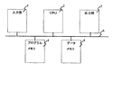
図1は、情報処理装置としての表示装置のハードウェア構成を示すブロック図である。図1において、入力部1は、ネットワーク等を介して複合機によってスキャンされた原稿データを入力する。CPU(Central Processing Unit)2は、各種処理のための演算、論理判断等を行い、バス6に接続された表示装置の各構成要素を制御する。また、CPU2は、後述するプログラムメモリ4に格納されているプログラムを実行することで、後述するような機能を提供したり、後述するようなフローチャートを実行したりする。 FIG. 1 is a block diagram illustrating a hardware configuration of a display device as an information processing device. In FIG. 1, an input unit 1 inputs document data scanned by a multifunction peripheral via a network or the like. A CPU (Central Processing Unit) 2 performs calculations for various processes, logical determinations, and the like, and controls each component of the display device connected to the bus 6. The CPU 2 executes a program stored in a program memory 4 to be described later, thereby providing a function as described later or executing a flowchart as described later.
出力部3は、データを出力する。なお、出力部3としては、LCD(Liquid Crystal Display)、CRT(Cathode Ray Tube)等によって構成される表示デバイスである。プログラムメモリ4は、プログラムを格納するメモリである。プログラムメモリ4は、ROM(Read Only Memory)であってもよいし、外部記憶装置又は記憶媒体等からプログラムがロードされるRAM(Random Access Memory)であってもよい。 The output unit 3 outputs data. The output unit 3 is a display device configured by an LCD (Liquid Crystal Display), a CRT (Cathode Ray Tube), or the like. The program memory 4 is a memory that stores a program. The program memory 4 may be a ROM (Read Only Memory) or a RAM (Random Access Memory) in which a program is loaded from an external storage device or a storage medium.
データメモリ5は、各種処理で生じたデータを格納する。なお、データメモリ5に格納される電子データとしては、例えば、後述するスキャン原稿、スキャン原稿と関連付けられたGUI部品(又はGUI部品データ)、手書きコマンドが除去されたスキャン原稿、登録データ等がある。また、データメモリ5は、例えば、RAMである。2次記憶装置7は、ハードディスクドライブ等の不揮発性の記憶媒体によって構成される。データメモリ5は、2次記憶装置7から処理に先立って、処理に必要なデータをロードしておくか、或いは必要があるごとに2次記憶装置7に格納されているデータを参照する。バス6は、CPU2の制御の対象とする各構成要素を指示するアドレス信号、CPU2が各構成要素を制御するためのコントロール信号、各構成要素間で相互にやりとりされるデータ等、の転送を行うためのバスである。 The data memory 5 stores data generated by various processes. The electronic data stored in the data memory 5 includes, for example, a scanned document described later, a GUI component (or GUI component data) associated with the scanned document, a scanned document from which handwritten commands are removed, registered data, and the like. . The data memory 5 is, for example, a RAM. The secondary storage device 7 is configured by a nonvolatile storage medium such as a hard disk drive. The data memory 5 loads data necessary for processing from the secondary storage device 7 prior to processing, or refers to data stored in the secondary storage device 7 whenever necessary. The bus 6 transfers an address signal that instructs each component to be controlled by the CPU 2, a control signal for the CPU 2 to control each component, data exchanged between the components, and the like. For the bus.
図2は、表示システムの構成を示すブロック図である。 FIG. 2 is a block diagram showing the configuration of the display system.
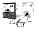
図2では、紙原稿21が複合機22でスキャンされ、原稿21に対応する電子化された原稿データとしてのスキャン原稿24が、表示装置23の表示画面に表示されている。また、図2では、原稿21上の手書きコマンド25及び26に対応した認識結果が、表示装置23の表示画面上で操作可能なGUI部品27及び28として生成され表示されている。ここで、GUI部品27は、手書きコマンド25に対応し、GUI部品28は、手書きコマンド26に対応している。なお、本実施の形態において、GUIとは、視覚的に表現され、ユーザ(操作者)がポインティングデバイス等によって操作を直感的に行うことができるグラフィカルユーザインターフェースのことである。
In FIG. 2, a
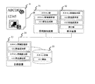
図3は、図2に示す表示システムの機能構成を示すブロック図である。なお、図3では、説明の簡略化のため、機能に基づき、原稿読取装置31と、表示装置32と、記録装置33と、に分けた例を示してある。図3において、原稿読取装置31は図2の複合機22に含まれ、表示装置32は図2の表示装置23に対応する。また、記録装置33は、図1のデータメモリ5に対応する。また、データベース35は、図1の2次記憶装置7に対応する。即ち、本実施の形態においては、データベース35は表示装置23に内蔵されるものとするが、外部装置として構成してもよい。
FIG. 3 is a block diagram showing a functional configuration of the display system shown in FIG. In FIG. 3, for simplification of description, an example in which the
図3に示した原稿21は、原稿読取装置31のスキャン部によりスキャンされる。スキャン原稿解釈部は、スキャン原稿を解釈し、GUI部品生成部は、スキャン原稿解釈部が解釈した結果等に基づいてGUI部品を生成する。スキャン原稿及び生成されたGUI部品は、ネットワーク34を介して表示装置32及び記録装置33に送られる。
The
表示装置32は、送られてきたスキャン原稿及びGUI部品を共に表示し、ユーザによる操作を受付ける。また、記録装置33は、送られてきたスキャン原稿及びGUI部品を関連付けてデータベース35に記録し、ユーザからの操作に応じて、記録したデータを読み出す。
The
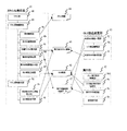
図4は、表示システムの機能構成をより詳細説明するための図である。これらの機能は、図2に示す複合機22及び表示装置23のハードウェア構成によって達成される。
FIG. 4 is a diagram for explaining the functional configuration of the display system in more detail. These functions are achieved by the hardware configuration of the
図4に示されるように、表示システムは、主な機能として、スキャン&表示部41と、実行部42と、GUI部品変更部43と、を含む。スキャン&表示部41は、原稿をスキャンして表示装置23の表示画面に表示する。実行部42は、ディスプレイ上のGUI部品や、メニュー項目を用いたユーザの操作指示に応じて、処理を実行する。GUI部品変更部43は、表示されているGUI部品を変更する。
As shown in FIG. 4, the display system includes a scan &
また、スキャン&表示部41は、スキャン部48と、スキャン原稿解釈部49と、スキャン原稿表示部4gと、を含む。スキャン部48は、原稿をスキャンする。スキャン原稿解釈部49は、スキャン部48がスキャンし、電子化データとして生成したスキャン原稿44を解釈する。スキャン原稿表示部4gは、スキャン原稿解釈部49が解析した結果である、手書きコマンドの除去後のスキャン原稿45や、GUI部品46等を表示する。
The scan &
また、スキャン原稿解釈部49は、指示解釈部4aと、指示対象特定部4bと、手書きコマンド除去部4cと、動作内容特定部4dと、動作内容関連付け部4eと、GUI部品生成部4fと、を含む。指示解釈部4aは、スキャン原稿44上の手書きコマンドを解釈し、手書きコマンドが指示する処理を特定する。なお、手書きコマンドが指示する処理とは、例えば、印刷や、再生、次ページ、音量変更、送信等の処理である。指示対象特定部4bは、実行可能処理定義データ47を参照して手書きコマンドの指示対象のデータ(指示対象オブジェクト)を特定する。なお、ここで、指示対象オブジェクトとは、例えば、動画、静止画、スキャン原稿自体(又はスキャン原稿全体)等、指示対象のデータのことである。手書きコマンド除去部4cは、手書きコマンドをスキャン原稿から除去し、除去後のスキャン原稿45を生成する。動作内容特定部4dは、手書きコマンドが指示する処理の動作内容を特定する。動作内容関連付け部4eは、手書きコマンドと、手書きコマンドが指示する処理の動作内容とを関連付ける。GUI部品生成部4fは、手書きコマンド等に対応するGUI部品46及びGUI部品46に対応するGUI部品データを生成する。例えば、GUI部品生成部4fは、指示解釈部4aが特定した手書きコマンドが指示する処理、指示対象特定部4bが特定した指示対象オブジェクト等に応じて、GUI部品46及びGUI部品46に対応するGUI部品データを生成する。
The scan
また、スキャン原稿表示部4gは、除去後のスキャン原稿表示部4hと、GUI部品表示部4iと、を含む。除去後のスキャン原稿表示部4hは、除去後のスキャン原稿45を表示する。GUI部品表示部4iは、GUI部品46を表示する。
The scanned
また、実行部42は、メニュー実行指示解釈部4mと、GUI部品実行指示解釈部4nと、実行許可判定部4oと、処理実行部4pと、を含む。メニュー実行指示解釈部4mは、メニュー項目による処理の実行指示を解釈する。GUI部品実行指示解釈部4nは、GUI部品46による処理の実行指示を解釈する。実行許可判定部4oは、指示された処理が実行可能な否かを判定する。処理実行部4pは、指示された処理を実行する。
The
また、GUI部品変更部43は、有効GUI部品一覧部4jと、GUI部品置換部4kと、次善指示対象特定部4lと、を含む。有効GUI部品一覧部4jは、変更可能な有効GUI部品を一覧表示する。GUI部品置換部4kは、指示されたGUI部品と、GUI部品とを、置換する。次善指示対象特定部4lは、求めるGUI部品46が、有効GUI部品一覧部4jが表示している一覧上に存在しない場合に次善の指示対象を特定する。
The GUI
(第1の実施の形態)
以下、図5から図15を用いて、画像形成装置22においてスキャンされた手書きコマンドが記入された原稿に基づいて、表示装置23の表示画面上に原稿と共に手書きコマンドに対応するGUI部品が表示される形態について説明する。さらに、表示装置23が、手書きコマンドとして解釈した部分をスキャン原稿から除去して表示する例について説明する。
(First embodiment)
Hereinafter, using FIG. 5 to FIG. 15, GUI parts corresponding to the handwritten commands are displayed on the display screen of the
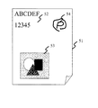
図5は、第1の実施形態におけるスキャン対象となる手書きコマンドが記入されている紙等の原稿の一例を示す図である。図5に示される原稿51は、テキスト領域52と、画像領域53と、を含み、更に手書きコマンド54が手書きで記述されている。
FIG. 5 is a diagram illustrating an example of a document such as paper on which handwritten commands to be scanned are entered according to the first embodiment. An original 51 shown in FIG. 5 includes a
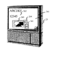
図6は、第1の実施形態におけるディスプレイに表示された表示画面の一例を示す図である。表示装置23上には図5に示した原稿51に対応する電子化されたデータであるスキャン原稿24が表示されている。スキャン原稿24は、テキスト領域62と、画像領域63と、を含む。また、ディスプレイ65上には図5の手書きコマンド54から生成された「印刷ボタン」のGUI部品64が表示されている。
FIG. 6 is a diagram illustrating an example of a display screen displayed on the display according to the first embodiment. On the
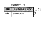
図7は、第1の実施形態における表示装置23に表示されたGUI部品のデータ(付属情報)の一例を示す図である。GUI部品データ71は、GUI部品に対応する機能の情報と、相対表示位置及びサイズの情報と、を含む。図7に示されるGUI部品データ71は、例えば、図6で示したGUI部品64等に対応する。図7に示されるGUI部品データ71は、指示対象に対する処理の機能として「印刷」が記録され、相対表示位置及びサイズとして(70,10),(90,25)が記録されていることを表している。図7に示すデータは、データメモリ5に格納される。
FIG. 7 is a diagram illustrating an example of GUI component data (attached information) displayed on the
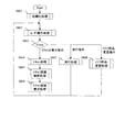
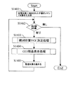
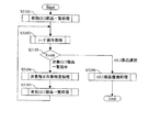
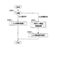
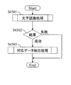
図8は、第1の実施形態における表示システムの全体処理の一例を示すフローチャートである。以下に説明する処理は、表示装置23のCPU2あるいは画像形成装置22の不図示のCPUが予めそれぞれの装置に格納されたプログラムに基づいて実行するものとする。ステップS801において、画像形成装置22及び表示装置23のそれぞれは、操作画面を表示する等の初期化動作を行う。続いてステップS802において、画像形成装置22及び表示装置23のそれぞれは、ユーザ操作処理を行い、ユーザの操作(又はEvent)を受け付ける。
FIG. 8 is a flowchart illustrating an example of overall processing of the display system according to the first embodiment. The processing described below is executed by the CPU 2 of the
続いてステップS803において、画像形成装置22及び表示装置23において、Eventの判定を行う。画像形成装置22は、ユーザによるスキャン&表示指示の検出が行われるとステップS804に進む。また、表示装置23において実行指示を検出するとステップS807に進み、表示装置23においてGUI部品変更指示を検出するとステップS808に進む。
In step S803, the
ステップS804では、画像形成装置22が、スキャン処理を行い、手書きコマンドが書かれた原稿をスキャンして電子化データとしてのスキャン原稿を取得し、表示装置23に転送する。続いてステップS805において、表示装置23は、スキャン原稿解釈処理を行い、例えばスキャン原稿中の手書きコマンドをGUI部品として解釈する。なお、表示装置23によるスキャン原稿解釈処理の詳細は、後述する図9に示す。続いてステップS806において表示装置23は、スキャン原稿表示処理を行い、手書きコマンドを除去したスキャン原稿と共にGUI部品を表示し、ステップS802の処理に戻る。GUI部品は、手書きコマンドが記述された位置に対応した同様の位置に表示される。なお、表示装置23によるスキャン原稿表示処理の詳細は、後述する図13に示す。
In step S804, the
一方、ステップS807では、表示装置23が、ユーザに指示されたメニュー項目やGUI部品に対応する処理を実行し、ステップS802の処理に戻る。なお、表示装置23による実行処理の詳細は、後述する図15に示す。また、ステップS808では、表示装置23が、GUI部品変更(又は置換)処理を行い、表示中のGUI部品を、指示されたGUI部品に変更し、ステップS802の処理に戻る。なお、表示装置23によるGUI部品変更処理の詳細は、後述する図31に示す。
On the other hand, in step S807, the
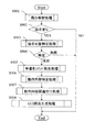
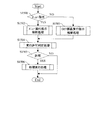
図9は、表示装置23によるスキャン原稿解釈処理の一例を示すフローチャートである。なお、図9に示す処理は、表示装置23による機能として、図4に示したスキャン原稿解釈部49が処理を行う(ハードウェアとしてはCPU2によって処理が行われる)ものとして説明を行う。
FIG. 9 is a flowchart showing an example of a scanned document interpretation process by the
ステップS901において、スキャン原稿解釈部49は、指示解釈処理を行い、電子化されたデータであるスキャン原稿中の手書きコマンドを解釈し、手書きコマンドが指示する処理を特定する。続いてステップS902において、スキャン原稿解釈部49は、ステップS901における解釈の結果に基づいて、手書きコマンドによる指示が有るか否かを判断する。スキャン原稿解釈部49は、手書きコマンドによる指示が有ると判断すると、ステップS903に進み、手書きコマンドによる指示がないと判断すると、スキャン原稿解釈処理を終了する。
In step S901, the scanned
ステップS903では、スキャン原稿解釈部49が、指示対象特定処理を行い、手書きコマンドの指示対象オブジェクト等を特定する。なお、指示対象特定処理の詳細は、後述する図19に示す。続いてステップS904において、スキャン原稿解釈部49は、ステップS903における手書きコマンドの指示対象オブジェクト等の特定が成功したか否かを判定する。スキャン原稿解釈部49は、ステップS903における手書きコマンドの指示対象オブジェクト等の特定が成功したと判定すると、ステップS905に進み、前記特定が成功しなかったと判定すると、スキャン原稿解釈処理を終了する。
In step S903, the scanned
ステップS905では、スキャン原稿解釈部49が、手書きコマンド除去処理を行い、手書きコマンドをスキャン原稿から除去する。なお、手書きコマンド除去処理の詳細は、後述する図11に示す。続いてステップS906において、スキャン原稿解釈部49は、動作内容特定処理を行い、手書きコマンドが指示する処理の動作内容を原稿上に記述された文字列や、原稿に埋め込まれた電子透かし、ユーザが決定(又は入力)する定義データ等から特定する。なお、動作内容特定処理の詳細は、後述する図45に示す。
In step S905, the scanned
続いてステップS907において、スキャン原稿解釈部49は、動作内容の関連付け処理を行い、手書きコマンドと、ステップS906において特定した手書きコマンドが指示する処理の動作内容と、を関連付ける。なお、動作内容関連付け処理の詳細は、後述する図46に示す。ステップS908において、スキャン原稿解釈部49は、ステップS907において関連付けられた手書きコマンド及び手書きコマンドが指示する処理の動作内容と、後述する図10に示される手書きコマンド定義データと、に基づいて、GUI部品生成処理を行う。GUI部品生成処理の結果、スキャン原稿解釈部49は、ステップS907において関連付けられた手書きコマンド及び手書きコマンドが指示する処理の動作内容に対応するGUI部品を生成し、スキャン原稿解釈処理を終了する。なお、GUI部品生成処理の詳細は、後述する図12に示す。
Subsequently, in step S907, the scanned
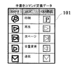
図10は、手書きコマンド定義データの一例を示す図である。図10に示されるように、手書きコマンド定義データは、手書きコマンドの情報であるストローク情報と、実行指示に係るコマンド(機能コマンド)と、表示装置23の表示画面上に表示されるGUI部品と、を含む。例えば、手書きコマンド定義データ101には、図5のスキャン原稿上の手書きコマンド54と同一のストローク情報が定義されている。また、手書きコマンド定義データ101には、図5のスキャン原稿上の手書きコマンド54に対応する「印刷」コマンドが定義されている。また、手書きコマンド定義データ101には、図6の「印刷ボタン」のGUI部品64と同一のGUI部品が定義されている。手書きコマンド定義データは、データメモリ5に格納される。
FIG. 10 is a diagram illustrating an example of handwritten command definition data. As shown in FIG. 10, the handwritten command definition data includes stroke information that is information of a handwritten command, a command (function command) related to an execution instruction, a GUI component displayed on the display screen of the
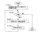
図11は、手書きコマンド除去処理の一例を示すフローチャートである。なお、図11に示す処理は、スキャン原稿解釈部49の、図4に示した手書きコマンド除去部4cが処理を行うものとして説明を行う。 FIG. 11 is a flowchart illustrating an example of the handwritten command removal process. The process shown in FIG. 11 will be described on the assumption that the handwritten command removal unit 4c shown in FIG.
ステップS1101において、手書きコマンド除去部4cは、例えば変数である「処理対象」に、抽出された手書きコマンドを識別する値等をセットし、「処理対象」を初期化する。例えば、抽出された手書きコマンドが2つ存在した場合、手書きコマンド除去部4cは、例えば変数である「処理対象」に、抽出された手書きコマンドの1つ目を示す値をセットする。 In step S1101, the handwritten command removal unit 4c sets, for example, a value for identifying the extracted handwritten command to “processing target” that is a variable, and initializes “processing target”. For example, when there are two extracted handwritten commands, the handwritten command removal unit 4c sets, for example, a value indicating the first extracted handwritten command to the “processing target” that is a variable.
ステップS1102において、手書きコマンド除去部4cは、「処理対象」にセットされている値に対応する、抽出された手書きコマンドが存在するか否かを判定する。手書きコマンド除去部4cは、「処理対象」にセットされている値に対応する、抽出された手書きコマンドが存在すると判定すると(ステップS1102において「有り」)、ステップS1103に進む。また、手書きコマンド除去部4cは、「処理対象」にセットされている値に対応する、抽出された手書きコマンドが存在しないと判定すると(ステップS1102において「無し」)、手書きコマンド除去処理を終了する。 In step S1102, the handwritten command removing unit 4c determines whether or not an extracted handwritten command corresponding to the value set in “processing target” exists. When the handwritten command removal unit 4c determines that there is an extracted handwritten command corresponding to the value set in “processing target” (“Yes” in Step S1102), the process proceeds to Step S1103. On the other hand, when the handwritten command removal unit 4c determines that there is no extracted handwritten command corresponding to the value set in the “processing target” (“None” in step S1102), the handwritten command removal process ends. .
ステップS1103では、手書きコマンド除去部4cが、対応ストローク除去処理を行い、「処理対象」にセットされている値に対応する手書きコマンドを削除する。つまり、手書きコマンド除去部4cは、処理対象の手書きコマンドに対応したストロークをスキャン原稿から除去する。続いてステップS1104において、手書きコマンド除去部4cは、「処理対象」にセットされている値を、例えば1つ進め、ステップS1102に戻る。 In step S1103, the handwritten command removing unit 4c performs the corresponding stroke removing process, and deletes the handwritten command corresponding to the value set in the “processing target”. That is, the handwritten command removing unit 4c removes the stroke corresponding to the handwritten command to be processed from the scanned document. Subsequently, in step S1104, the handwritten command removal unit 4c advances the value set in “processing target” by one, for example, and returns to step S1102.
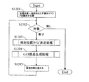
図12は、GUI部品生成処理の一例を示すフローチャートである。なお、図12に示す処理は、スキャン原稿解釈部49の、図4に示したGUI部品生成部4fが処理を行うものとして説明を行う。
FIG. 12 is a flowchart illustrating an example of GUI component generation processing. The process shown in FIG. 12 will be described on the assumption that the GUI
ステップS1201において、GUI部品生成部4fは、例えば変数である「処理対象」に、抽出された手書きコマンドを識別する値等をセットし、「処理対象」を初期化する。例えば、抽出された手書きコマンドが2つ存在した場合、手書きコマンド除去部4cは、例えば変数である「処理対象」に、抽出された手書きコマンドの1つ目を示す値をセットする。
In step S1201, the GUI
ステップS1202において、GUI部品生成部4fは、「処理対象」にセットされている値に対応する、抽出された手書きコマンドが存在するか否かを判定する。GUI部品生成部4fは、「処理対象」にセットされている値に対応する、抽出された手書きコマンドが存在すると判定すると(ステップS1202において「有り」)、ステップS1203に進む。また、GUI部品生成部4fは、「処理対象」にセットされている値に対応する、抽出された手書きコマンドが存在しないと判定すると(ステップS1202において「無し」)、GUI部品生成処理を終了する。
In step S1202, the GUI
ステップS1203では、GUI部品生成部4fが、相対位置サイズ決定処理を行い、「処理対象」にセットされている値に対応する手書きコマンドに対応したストロークのスキャン原稿に対する相対位置と、サイズと、を求める。続いてステップS1204において、GUI部品生成部4fは、GUI部品生成処理を行い、ステップS1203において求めた相対位置(相対表示位置)上に表示すべく、求めたサイズでGUI部品を生成する。
In step S1203, the GUI
続いてステップS1205において、GUI部品生成部4fは、「処理対象」にセットされている値を、例えば1つ進め、ステップS1202に戻る。
Subsequently, in step S1205, the GUI
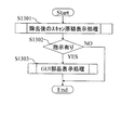
図13は、スキャン原稿表示処理の一例を示すフローチャートである。なお、図13に示す処理は、表示装置23の機能として、図4に示したスキャン原稿表示部4gが処理を行うものとして説明を行う。
FIG. 13 is a flowchart illustrating an example of a scanned document display process. The processing shown in FIG. 13 will be described on the assumption that the scan
ステップS1301において、スキャン原稿表示部4gは、除去後のスキャン原稿表示処理を行い、手書きコマンドが除去された状態のスキャン原稿を表示装置23に表示する。続いてステップS1302において、スキャン原稿表示部4gは、例えばスキャン原稿中の手書きコマンドの解釈等に基づいて、手書きコマンドによる指示が有るか否かを判断する。スキャン原稿表示部4gは、手書きコマンドによる指示が有ると判断すると、ステップS1303に進み、手書きコマンドによる指示がないと判断すると、スキャン原稿表示処理を終了する。
In step S1301, the scanned
ステップS1303では、スキャン原稿表示部4gが、GUI部品表示処理を行い、手書きコマンドによる指示に対応するGUI部品を表示する。なお、GUI部品表示処理の詳細は、後述する図14に示す。
In step S1303, the scanned
図14は、GUI部品表示処理の一例を示すフローチャートである。なお、図14に示す処理は、スキャン原稿表示部4gの、図4に示したGUI部品表示部4iが処理を行うものとして説明を行う。
FIG. 14 is a flowchart illustrating an example of GUI component display processing. The process shown in FIG. 14 will be described on the assumption that the GUI
ステップS1401において、GUI部品表示部4iは、例えば変数である「処理対象」に、抽出された手書きコマンドを識別する値等をセットし、「処理対象」を初期化する。例えば、抽出された手書きコマンドが2つ存在した場合、GUI部品表示部4iは、例えば変数である「処理対象」に、抽出された手書きコマンドの1つ目を示す値をセットする。
In step S1401, the GUI
ステップS1402において、GUI部品表示部4iは、「処理対象」にセットされている値に対応する、抽出された手書きコマンドが存在するか否かを判定する。GUI部品表示部4iは、「処理対象」にセットされている値に対応する、抽出された手書きコマンドが存在すると判定すると(ステップS1402において「有り」)、ステップS1403に進む。また、GUI部品表示部4iは、「処理対象」にセットされている値に対応する、抽出された手書きコマンドが存在しないと判定すると(ステップS1402において「無し」)、GUI部品表示処理を終了する。
In step S1402, the GUI
ステップS1403では、GUI部品表示部4iが、絶対位置サイズ決定処理を行う。GUI部品表示部4iは、例えば、図12に示したステップS1204等において生成されたGUI部品(又はGUI部品のGUI部品データ)に基づいて、GUI部品を表示装置23上に表示する際の絶対位置と、サイズと、を決定する。続いてステップS1404において、GUI部品表示部4iは、GUI部品表示処理を行い、処理対象の手書きコマンドに対応するGUI部品を、ステップS1403において決定された位置及びサイズで、表示装置23に表示する。
In step S1403, the GUI
続いてステップS1405において、GUI部品表示部4iは、「処理対象」にセットされている値を、例えば1つ進め、ステップS1402に戻る。
Subsequently, in step S1405, the GUI
図15は、実行処理の一例を示すフローチャートである。なお、図15に示す処理は、表示装置23の、図4に示した実行部42が処理を行うものとして説明を行う。
FIG. 15 is a flowchart illustrating an example of execution processing. The process shown in FIG. 15 will be described on the assumption that the
ステップS1501において、実行部42は、ユーザの操作が、メニュー項目による処理の実行指示か否かを判定する。実行部42は、ユーザの操作が、メニュー項目による処理の実行指示であると判定すると、ステップS1502に進み、ユーザの操作が、メニュー項目による処理の実行指示でないと判定すると、ステップS1503に進む。
In step S1501, the
ステップS1502では、実行部42が、メニュー実行指示解釈処理を行い、メニュー項目による処理の実行指示を解釈する。一方、ステップS1503では、実行部42が、GUI部品実行指示解釈処理を行い、GUI部品による処理の実行指示を解釈する。例えば、実行部42は、ユーザによって操作されたGUI部品に対応するGUI部品データに基づいて、処理(処理の機能)や、処理の動作内容、処理の指示対象等を特定する。
In step S1502, the
ステップS1504では、実行部42が、実行許可判定処理を行い、ユーザの実行指示が実行可能な指示か否かを判定する。なお、実行許可判定処理の詳細は、後述する図41に示す。続いてステップS1505において、実行部42は、ステップS1504における判定結果に基づいて、実行を許可すると判断すると、ステップS1506に進み、実行を許可しないと判断すると、実行処理を終了する。
In step S1504, the
ステップS1506では、実行部42が、処理実行処理の指示を行い、各処理が実行される。
In step S1506, the
上述したように、第1の実施形態によれば、表示装置23は、手書きコマンドの認識結果をGUI部品としてディスプレイ上に発現させる。よって、誤認識を防止するための特別な確認ステップを不要とし、同時に誤動作のリスクが回避可能となり、表示中の原稿データに対する操作性を向上させることができる。
As described above, according to the first embodiment, the
また、第1の実施形態によれば、表示装置23は、例えば図6に示されるように、GUI部品を表示装置23の表示画面上に常駐させる。よって、ユーザは、GUI部品を用いて、何回でも原稿データ等に対する処理を行うことが可能となり、表示中の原稿データに対する操作性を向上させることができる。
Further, according to the first embodiment, the
また、第1の実施形態によれば、表示装置23は、一般の原稿に記入された手書きコマンドを認識し、認識結果をGUI部品として発現させる。よって、専用のシート等を用いる必要がなく、より簡単に表示中の原稿データに対する操作性を向上させることができる。
Further, according to the first embodiment, the
また、第1の実施形態によれば、表示装置23は、手書きコマンドの認識結果をGUI部品として手書きコマンドに対応する位置に発現させると共に、スキャン原稿をディスプレイ上に表示する。よって、ユーザは、スキャン原稿をディスプレイで確認した後で(又は確認しながら)、GUI部品等を用いて印刷等の処理の実行指示が可能となり、表示中の原稿データに対する操作性を向上させることができる。
Further, according to the first embodiment, the
また、第1の実施形態では、表示装置23は、図3のデータベース35に示したように、スキャン原稿と、対応するGUI部品と、を関連付けて格納、管理する。よって、スキャン原稿を再利用した際に、対応するGUI部品も再利用可能となるので、表示中の原稿データに対する操作性を向上させることができる。
In the first embodiment, as shown in the
なお、第1の実施形態では、表示装置23が、手書きコマンドを除去したスキャン原稿を表示する例を示したが、手書きコマンドを除去しないままのスキャン原稿を表示してもよいし、スキャン原稿に対する元原稿をデータメモリ5等より検索して表示してもよい。
In the first embodiment, an example is shown in which the
(第2の実施の形態)
以下、図16から図24を用いて、表示装置23が、原稿中の特定領域を指示対象としたGUI部品を表示する例について説明する。なお、画像形成装置22及び表示装置23を含む表示システムの構成は第1の実施の形態と同様であるので、その説明を省略する。
(Second Embodiment)
Hereinafter, an example in which the
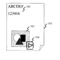
図16は、第2の実施形態におけるスキャン対象となる手書きコマンドが記入されている紙等の原稿を示す図(その1)である。図16に示される原稿161は、テキスト領域162と、画像領域163と、を含み、更に手書きコマンド164が、画像領域163に重なる形で、手書きで記入されている。
FIG. 16 is a diagram (No. 1) illustrating a document such as paper on which handwritten commands to be scanned are entered in the second embodiment. A
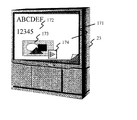
図17は、第2の実施形態における表示装置23に表示された表示画面を示す図(その1)である。表示装置23の表示画面上には図16に示した原稿161に対応する電子化されたデータとしてスキャン原稿171が表示されている。スキャン原稿171は、テキスト領域172と、画像領域173と、を含む。また、表示装置23上には図16の手書きコマンド164から生成された「再生ボタン」のGUI部品174が表示されている。なお画像領域173は、スキャン原稿171に対して表示装置23等が検索した元原稿の対応領域にあった動画に関連付けられており、「再生ボタン」は前記動画に対する操作を可能としていることを示している。
FIG. 17 is a diagram (part 1) illustrating a display screen displayed on the
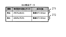
図18は、第2の実施形態における表示装置23に表示されたGUI部品のデータを示す図(その1)である。GUI部品データ181は、GUI部品に対応する機能の情報と、相対表示位置及びサイズの情報と、指示対象のオブジェクトの情報と、を含む。図18に示されるGUI部品データ181は、例えば、図17で示したGUI部品174に対応する。図18に示されるGUI部品データ181は、指示対象として「動画オブジェクト173」が記録され、指示対象に対する処理の機能として「再生」が記録され、相対表示位置及びサイズとして(50,85),(60,95)が記録されていることを表している。GUI部品データ181は、データメモリ5に格納される。
FIG. 18 is a diagram (No. 1) illustrating data of a GUI component displayed on the
図19は、指示対象特定処理の一例を示すフローチャートである。なお、図19に示す処理は、表示装置23の機能として、スキャン原稿解釈部49の、図4に示した指示対象特定部4bが処理を行うものとして説明を行う。
ステップS1901において、指示対象特定部4bは、元原稿検索処理を行い、スキャン原稿に係る原稿の元原稿を検索する。続いてステップS1902において、指示対象特定部4bは、ステップS1901における検索の結果に基づいて、元原稿が有ったと判定すると、ステップS1904に進み、元原稿が無かったと判定すると、ステップS1903に進む。
FIG. 19 is a flowchart illustrating an example of the instruction target specifying process. The processing shown in FIG. 19 will be described on the assumption that the instruction
In step S1901, the instruction
ステップS1903では、指示対象特定部4bが、オブジェクト抽出処理を行い、スキャン原稿を画像解析することにより、テキストや、図形、画像等のオブジェクトを抽出し、ステップS1904に進む。
In step S1903, the instruction
ステップS1904では、指示対象特定部4bが、例えば変数である「処理対象」に、抽出された手書きコマンドを識別する値等をセットし、「処理対象」を初期化する。例えば、抽出された手書きコマンドが2つ存在した場合、指示対象特定部4bは、例えば変数である「処理対象」に、抽出された手書きコマンドの1つ目を示す値をセットする。
In step S1904, the instruction
ステップS1905では、指示対象特定部4bが、「処理対象」にセットされている値に対応する、抽出された手書きコマンドが存在するか否かを判定する。指示対象特定部4bは、「処理対象」にセットされている値に対応する、抽出された手書きコマンドが存在すると判定すると(ステップS1905において「有り」)、ステップS1906に進む。また、指示対象特定部4bは、「処理対象」にセットされている値に対応する、抽出された手書きコマンドが存在しないと判定すると(ステップS1905において「無し」)、指示対象特定処理を終了する。
In step S1905, the instruction
ステップS1906では、指示対象特定部4bが、図4に示した指示対象種類に対応する実行可能処理定義データ47等を用い、対応オブジェクト特定処理を行う。指示対象特定部4bは、元原稿又はステップS1903で抽出したオブジェクトの中から、処理対象の手書きコマンドが指示対象とするオブジェクトを特定する。なお、実行可能処理定義データの詳細は、後述する図20に示す。また、対応オブジェクト特定処理の詳細は、後述する図21に示す。
In step S1906, the instruction
続いてステップS1907において、指示対象特定部4bは、ステップS1906における対応オブジェクト特定処理で、処理対象の手書きコマンドが指示対象とするオブジェクトの特定が成功したか否かを判定する。指示対象特定部4bは、処理対象の手書きコマンドが指示対象とするオブジェクトの特定が成功したと判定すると、ステップS1908に進む。また、指示対象特定部4bは、処理対象の手書きコマンドが指示対象とするオブジェクトの特定が失敗したと判定すると、ステップS1909に進む。
Subsequently, in step S1907, the instruction
ステップS1908では、指示対象特定部4bが、ステップS1906において特定されたオブジェクトを、処理対象の手書きコマンドの指示対象とする。一方、ステップS1909では、指示対象特定部4bが、例えば図9のS901等において手書きコマンドとして認識されたこと自体、誤りと判断して、現在処理対象の手書きコマンドとしているものをスキャン原稿から削除し、ステップS1910に進む。
In step S1908, the instruction
ステップS1910では、指示対象特定部4bが、「処理対象」にセットされている値を、例えば1つ進め、ステップS1905に戻る。
In step S1910, the instruction
図20は、図4に示す指示対象種類に対応する実行可能処理定義データ47の一例を示す図である。これらのデータは、データメモリ5に保持される。図20に示す実行可能処理定義データは、指示対象種類と、指示対応種類に対応する実行可能処理リストと、を含む。例えば、実行可能処理定義データ201には、図17で示した動画オブジェクト173等に対応した指示対象種類「動画」が定義されている。また、実行可能処理定義データ201には、「動画」に対応する実行可能な処理リストとして、「印刷」、「再生」、「音量変更」、「送信」の各処理が定義されている。
FIG. 20 is a diagram illustrating an example of the executable
図21は、対応オブジェクト特定処理の一例を示すフローチャートである。なお、図21に示す処理は、図4に示した指示対象特定部4bが処理を行うものとして説明を行う。
FIG. 21 is a flowchart illustrating an example of the corresponding object specifying process. Note that the processing illustrated in FIG. 21 will be described assuming that the instruction
ステップS2101において、指示対象特定部4bは、図9のステップS901等の指示解釈処理で解釈された手書きコマンドの解釈結果を識別する値等をセットし、「対象解釈」を初期化する。例えば、手書きコマンドの解釈結果が2つ存在した場合、指示対象特定部4bは、例えば変数である「対象解釈」に、手書きコマンドの解釈結果の1つ目を示す値をセットする。
In step S2101, the instruction
ステップS2102では、指示対象特定部4bが、「対象解釈」にセットされている値に対応する、手書きコマンドの解釈結果が存在するか否かを判定する。指示対象特定部4bは、「対象解釈」にセットされている値に対応する、手書きコマンドの解釈結果が存在すると判定すると(ステップS2102において「有り」)、ステップS2103に進む。また、指示対象特定部4bは、「対象解釈」にセットされている値に対応する、手書きコマンドの解釈結果が存在しないと判定すると(ステップS2102において「無し」)、対応オブジェクト特定処理を終了する。
In step S2102, the instruction
ステップS2103では、指示対象特定部4bが、手書きコマンド付近にあるオブジェクトを識別する値等をセットし、「指示対象オブジェクト」を初期化する。手書きコマンド付近にあるオブジェクトが2つ存在した場合指示対象特定部4bは、例えば変数である「指示対象オブジェクト」に、手書きコマンド付近にあるオブジェクトの内最も手書きコマンドの近くにあるオブジェクトを示す値をセットする。
In step S2103, the instruction
ステップS2104では、指示対象特定部4bが、「指示対象オブジェクト」にセットされている値に対応する、手書きコマンド付近にあるオブジェクトが存在するか否かを判定する。指示対象特定部4bは、「指示対象オブジェクト」にセットされている値に対応する、手書きコマンド付近にあるオブジェクトが存在すると判定すると(ステップS2104において「有り」)、ステップS2105に進む。また、指示対象特定部4bは、「指示対象オブジェクト」にセットされている値に対応する、手書きコマンド付近にあるオブジェクトが存在しないと判定すると(ステップS2104において「無し」)、ステップS2108に進む。
In step S2104, the instruction
ステップS2105では、指示対象特定部4bが、図20に示した実行可能処理定義データ等を参照して有効性判定処理を行う。指示対象特定部4bは、例えば図9のS901等の指示解釈処理において解釈された手書きコマンドの指示解釈(つまり、手書きコマンドが指示する処理)が、指示対象オブジェクトに対して有効な処理か否かを判定する。
In step S2105, the instruction
指示対象特定部4bは、手書きコマンドの指示解釈が指示対象オブジェクトに対して有効な処理でないと判定すると、ステップS2107に進む。また、指示対象特定部4bは、手書きコマンドの指示解釈が指示対象オブジェクトに対して有効な処理であると判定すると、対応オブジェクト特定処理を終了する。
Instruction
ステップS2107では、指示対象特定部4bが、「指示対象オブジェクト」にセットされている値を、例えば1つ進め、ステップS2104に戻る。また、ステップS2108では、指示対象特定部4bが、「対象解釈」にセットされている値を、例えば1つ進め、ステップS2102に戻る。
In step S2107, the instruction
なお、ステップS2105の有効性判定処理において、指示対象特定部4bは、図20に示す実行可能処理定義データ等を参照すると共に、例えば、同一指示対象オブジェクトに対する機能が重複しているか否かに基づいて有効性を判定するようにしてもよい。つまり、同一指示対象オブジェクトに対して、類似する手書きコマンドが2つ原稿に記入されていた場合、指示対象特定部4bは、同一指示対象オブジェクトに対する機能(又は処理)が重複しているため、有効ではないと判断するようにしてもよい。一方、上述したような場合、指示対象特定部4bは、有効ではないと判断せず、同一の機能(例えば、再生)のコマンドではなく異なる機能(例えば、再生と、音量変更と、)のコマンドと解釈し、有効であると判定するようにしてもよい。
In the validity determination process in step S2105, the instruction
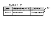
図22は、第2の実施形態におけるスキャン対象となる手書きコマンドが記入されている原稿の一例(その2)である。図22に示される原稿221は、テキスト領域222と、表領域223と、を含み、更に手書きコマンド224が、表領域223に重なる形で、手書きで記入されている。
FIG. 22 is an example (part 2) of a document in which a handwritten command to be scanned is entered in the second embodiment. A
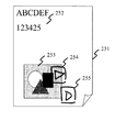
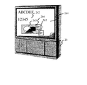
図23は、第2の実施形態における表示装置23上の表示画面の一例(その2)である。表示装置23の表示画面上には図22に示した原稿221に対応する電子化されたデータとしてスキャン原稿231が表示されている。スキャン原稿231は、テキスト領域232と、表領域233と、を含む。なお、表領域233は、スキャン原稿231に対して表示装置23が検索した元原稿の対応領域にあった表に関連付けられている。
また、表示装置23の表示画面上にはスキャン原稿自体を処理対象とした「次ページボタン」のGUI部品234が表示されている。これは、図22の手書きコマンド224に対応する「再生ボタン」のGUI部品では、指示対象であった前記表に対して処理が不可能なために、表示装置23によって、指示対象及びGUI部品が変更されているからである。
FIG. 23 is an example (part 2) of the display screen on the
On the display screen of the
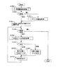
図24は、第2の実施形態における表示装置23に表示されたGUI部品のデータの一例(その2)である。GUI部品データ241は、GUI部品に対応する機能の情報と、相対表示位置及びサイズの情報と、指示対象のオブジェクトの情報と、を含む。図24に示されるGUI部品データ241は、例えば、図23で示したGUI部品234に対応する。図24に示されるGUI部品データ241は、指示対象として「スキャン原稿自体231」が記録され、指示対象に対する処理の機能として「次ページ」が記録されていることを表している。また、図24に示されるGUI部品データ241は、相対表示位置及びサイズとして(50,85),(60,95)が記録されていることを表している。GUI部品データ241は、データメモリ5に保持される。
FIG. 24 is an example (part 2) of GUI component data displayed on the
上述したように、第2の実施形態によれば、表示装置23は、GUI部品の指示対象を適切に特定する。よって、表示中の原稿データに対する操作性を向上させることができる。また、第2の実施形態によれば、表示装置23は、有効なGUI部品だけを生成する。よって、表示中の原稿データに対する操作性を向上させることができる。
As described above, according to the second embodiment, the
(第3の実施の形態)
以下、図25から図35を用いて、表示装置23が、誤認識したGUI部品を変更する例について説明する。画像形成装置22及び表示装置23を含む表示システムの構成は第1の実施の形態と同様であるので、その構成は省略する。
(Third embodiment)
Hereinafter, an example in which the
図25は、第3の実施形態におけるスキャン対象となる手書きコマンドが記入されている紙等の原稿の一例(その1)である。図25に示される原稿251は、テキスト領域252と、画像領域253と、を含み、更に、手書きコマンド254及び255が、手書きで記入されている。
FIG. 25 is an example (part 1) of a document such as paper on which handwritten commands to be scanned are entered according to the third embodiment. An original 251 shown in FIG. 25 includes a
図26は、第3の実施形態における表示装置23に表示された表示画面を示す図(その1)である。表示装置23上には図25に示した原稿251に対応する電子化されたデータとしてスキャン原稿261が表示されている。スキャン原稿261は、テキスト領域262と、画像領域263と、を含む。また、表示装置23上には図25の手書きコマンド254及び255から生成された「再生ボタン」のGUI部品264及び265が表示されている。なお画像領域263は、スキャン原稿261に対して表示装置23等が検索した元原稿の対応領域にあった動画に関連付けられており、「再生ボタン」は前記動画に対する操作を可能としていることを示している。
FIG. 26 is a diagram (part 1) illustrating a display screen displayed on the
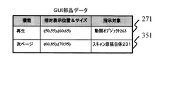
図27は、第3の実施形態における表示装置23に表示されたGUI部品のデータの一例(その1)である。GUI部品データは、GUI部品に対応する機能の情報と、相対表示位置及びサイズの情報と、指示対象のオブジェクトの情報と、を含む。図27のGUI部品データは、データメモリ5に保持される。図27に示されるGUI部品データ271は、例えば、図26で示したGUI部品264に対応する。図27に示されるGUI部品データ271は、指示対象として「動画オブジェクト263」が記録され、指示対象に対する処理の機能として「再生」が記録され、相対表示位置及びサイズとして(50,55),(60,65)が記録されていることを表している。なお、ここでは同一指示対象オブジェクトに対する同一機能(又は処理)GUI部品の重複を許すものとして説明しているので再生ボタンが2つ存在しているが、重複を許さない場合には異なる機能のGUI部品が存在することになる。
FIG. 27 is an example (part 1) of GUI component data displayed on the
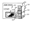
図28は、第3の実施形態における表示装置23に表示されたGUI部品変更操作画面を示す図(その1)である。図28に示される表示装置23の表示画面上には図25に示した原稿251に対応するスキャン原稿261が表示されている。また、図28に示される表示装置23の表示画面上にはスキャン原稿261を構成するテキスト領域262と、画像領域263と、共に、図25の手書きコマンド254及び255から生成された「再生ボタン」のGUI部品264及び265が表示されている。
FIG. 28 is a diagram (No. 1) illustrating a GUI component change operation screen displayed on the
また、図28では、ユーザによる「再生ボタン」のGUI部品265を指定した有効GUI一覧ウィンドウの表示指示操作に対応した、有効GUI一覧ウィンドウ281が表示されている例が示されている。また、図28では、有効GUI一覧ウィンドウ281の内、「音量変更ボタン」のGUI部品282が選択状態になっている例が示されている。また、図28では、有効GUI一覧の中のGUI部品の指示対象オブジェクト263が、ユーザに判別可能なように例えば太枠で表示されている例が示されている。
FIG. 28 shows an example in which an effective
なお、例えば、表示装置23は、ユーザがポインティングデバイスを用いてGUI部品上で長押し等の操作を行うと、ユーザによる有効GUI一覧ウィンドウの表示指示操作であると判断する。そして表示装置23は、図28に示されるような有効GUI一覧ウィンドウ281を表示装置23上に表示する。
For example, when the user performs an operation such as a long press on the GUI component using the pointing device, the
図29は、図26に示した表示画面に対して、図28に示したようなGUI部品の変更操作を行った後の表示装置23に表示された表示画面の一例を示す図である。図29に示される表示画面は、図26に示した表示画面と比べて、「再生ボタン」のGUI部品265が、「音量変更ボタン」のGUI部品291に変更されている点が異なる。
FIG. 29 is a diagram showing an example of the display screen displayed on the
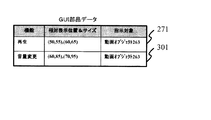
図30は、第3の実施形態における表示装置23に表示されたGUI部品のデータを示す図(その2)である。図30に示されるGUI部品データは、図27に示したGUI部品データと比べて、GUI部品データ272が、GUI部品データ301に変更されている(又は置き換えられている)点が異なる。図30のGUI部品データは、データメモリ5に保持される。
FIG. 30 is a diagram (part 2) illustrating the data of the GUI component displayed on the
図31は、GUI部品変更処理の一例を示すフローチャートである。なお、図31に示す処理は、表示装置23の機能として、図4に示したGUI部品変更部43が処理を行うものとして説明を行う。
FIG. 31 is a flowchart illustrating an example of GUI component change processing. The processing shown in FIG. 31 will be described on the assumption that the GUI
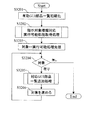
ステップS3101において、GUI部品変更部43は、有効GUI部品一覧処理を行う。GUI部品変更部43は、表示中のGUI部品の内、長押し等で選択されたGUI部品の指示対象オブジェクトを指示対象とすることが可能なGUI部品の一覧(有効GUI一覧ウィンドウ)を表示する。なお、有効GUI部品一覧処理の詳細は、後述する図32に示す。
In step S <b> 3101, the GUI
ステップS3102では、GUI部品変更部43が、ユーザ操作処理を行い、ユーザの操作(又はEvent)を受け付ける。GUI部品変更部43は、ユーザが、次善GUI部品一覧表示指示を行ったと判定するとステップS3104に進み、GUI部品選択指示を行ったと判定するとステップS3106に進む。
In step S3102, the GUI
ステップS3104では、GUI部品変更部43が、次善指示対象の特定処理を行い、現在スキャン原稿中で選択しているGUI部品が指示対象とする指示対象オブジェクトに代わる、次善の指示対象オブジェクトを特定する。続いてステップS3105において、GUI部品変更部43は、有効GUI部品一覧処理を行い、ステップS3104において特定した次善の指示対象オブジェクトに関する有効GUI部品の一覧(有効GUI一覧ウィンドウ)を表示し、ステップS3102に戻る。
In step S3104, the GUI
一方、ステップS3106では、GUI部品変更部43が、GUI部品置換処理を行う。GUI部品変更部43は、現在スキャン原稿中で選択しているGUI部品(例えば、図28のGUI部品265)と、有効GUI一覧ウィンドウの中から選択しているGUI部品(例えば、図28のGUI部品282)と、を置き換える。
On the other hand, in step S3106, the GUI
図32は、有効GUI部品一覧処理の一例を示すフローチャートである。なお、図32の示す処理は、GUI部品変更部43の、図4に示した有効GUI部品一覧部4jが処理を行うものとして説明を行う。 FIG. 32 is a flowchart illustrating an example of a valid GUI component list process. The processing shown in FIG. 32 will be described on the assumption that the effective GUI component list unit 4j shown in FIG.
ステップS3201において、有効GUI部品一覧部4jは、有効GUI部品の一覧を初期化する。続いてステップS3202において、有効GUI部品一覧部4jは、指示対象種類に対応する実行可能処理を取得するための処理を行う。有効GUI部品一覧部4jは、図20に示したような実行可能処理定義データより、現在指示対象としているオブジェクト(例えば、動画、静止画、スキャン原稿自体等)に対応する実行可能処理リストを取得する。例えば、有効GUI部品一覧部4jは、現在指示対象としているオブジェクトが動画の場合、実行可能処理リストとして、「印刷、再生、音量変更、送信」等を取得する。 In step S3201, the valid GUI component list unit 4j initializes a list of valid GUI components. Subsequently, in step S3202, the valid GUI component list unit 4j performs a process for acquiring an executable process corresponding to the instruction target type. The effective GUI component list unit 4j obtains an executable process list corresponding to an object (for example, a moving image, a still image, a scanned document itself, etc.) that is currently instructed from the executable process definition data as shown in FIG. To do. For example, when the object currently instructed is a moving image, the valid GUI component list unit 4j acquires “print, playback, volume change, transmission” and the like as an executable process list.
ステップS3203では、有効GUI部品一覧部4jが、ステップS3202で取得した実行可能処理リストに含まれる実行可能処理を識別する値等をセットし、「処理対象」を初期化する。例えば、実行可能処理リストに実行可能処理が4つ存在した場合、有効GUI部品一覧部4jは、例えば変数である「処理対象」に、実行可能処理リストの最初に記録されている実行可能処理を示す値をセットする。 In step S3203, the valid GUI component list unit 4j sets a value or the like for identifying the executable process included in the executable process list acquired in step S3202, and initializes “processing target”. For example, when there are four executable processes in the executable process list, the effective GUI component list unit 4j displays the executable process recorded at the beginning of the executable process list in, for example, the variable “processing target”. Set the indicated value.
ステップS3204では、有効GUI部品一覧部4jが、「処理対象」にセットされている値に対応する、実行可能処理が存在するか否かを判定する。有効GUI部品一覧部4jは、「処理対象」にセットされている値に対応する、実行可能処理が存在すると判定すると(ステップS3204において「有り」)、ステップS3205に進む。また、有効GUI部品一覧部4jは、「処理対象」にセットされている値に対応する、実行可能処理が存在しないと判定すると(ステップS3204において「無し」)、有効GUI部品一覧処理を終了する。 In step S3204, the valid GUI component list unit 4j determines whether there is an executable process corresponding to the value set in “processing target”. If the valid GUI component list unit 4j determines that there is an executable process corresponding to the value set in “processing target” (“YES” in step S3204), the process proceeds to step S3205. If the valid GUI component list unit 4j determines that there is no executable process corresponding to the value set in the “processing target” (“none” in step S3204), the valid GUI component list process ends. .
ステップS3205では、有効GUI部品一覧部4jが、対応GUI部品一覧追加処理を行い、処理対象の指示対象オブジェクトの実行可能処理に対応したGUI部品を、有効GUI部品の一覧に追加し、一覧を表示する。 In step S3205, the valid GUI component list unit 4j performs a corresponding GUI component list addition process, adds a GUI component corresponding to the executable process of the instruction target object to be processed to the list of valid GUI components, and displays the list. To do.
続いてステップS3206において、有効GUI部品一覧部4jは、「処理対象」にセットされている値を、例えば1つ進め、ステップS3204に戻る。なお、有効GUI部品一覧部4jは、有効GUI部品一覧処理において、図20に示す実行可能処理定義データに定義されている順序で、有効GUI部品の一覧を表示してもよい。また、有効GUI部品一覧部4jは、有効GUI部品一覧処理において、例えばスキャン原稿解釈部49等の手書きコマンドの解釈結果等に基づいて、手書きコマンドの形状に近いGUI部品から順に、有効GUI部品の一覧を表示してもよい。このようにすることによって、ユーザは、一覧の上から順にGUI部品を探すことによって、自身が書いた手書きコマンドの形状に近い、有効なGUI部品を見つけることができる。また、有効GUI部品一覧部4jは、有効GUI部品一覧処理において、手書きコマンドの形状と、GUI部品との形状と、の差が、一定の閾値以上のGUI部品を、有効GUI部品の一覧から除外するようにしてもよい。このようにすることによって、手書きコマンドの形状と一定の閾値以上形状が異なるGUI部品を一覧から削除することが可能となり、適切なGUI部品を一覧に表示することができる。
Subsequently, in step S3206, the valid GUI component list unit 4j advances the value set in “processing target” by one, for example, and returns to step S3204. The valid GUI component list unit 4j may display a list of valid GUI components in the order defined in the executable process definition data shown in FIG. 20 in the valid GUI component list process. Further, the effective GUI component list unit 4j, in the effective GUI component list process, determines the effective GUI component in order from the GUI component closest to the shape of the handwritten command based on the interpretation result of the handwritten command from the scanned
図33は、第3の実施形態における表示装置23に表示されたGUI部品変更操作画面を示す一例(その2)である。図33には、図28に示したGUI部品変更操作画面において、ユーザが次善GUI部品一覧指示操作を行った結果、次善の指示対象オブジェクトに対する有効GUI部品の一覧331が表示された例が示されている。なお、ユーザの次善GUI部品一覧指示操作とは、例えば次善GUI部品一覧表示ボタン283を押下する等の操作のことである。また、図33には、有効GUI部品の一覧331の内、ユーザによって「次ページボタン」のGUI部品332が選択されている例が示されている。
FIG. 33 is an example (part 2) illustrating a GUI component change operation screen displayed on the
図33に示される有効GUI部品の一覧331は、GUI部品265の指示対象オブジェクト263が、次善の指示対象オブジェクト261に変わったことに対応して、表示装置23に表示される。また、有効GUI部品の一覧331は、GUI部品265の指示対象オブジェクトが変化したことがわかるように、表示装置23に表示される。
A
図34は、図33に示したようなGUI部品変更操作画面において、GUI部品変更操作が行われた後の表示装置23に表示された表示画面の一例を示す図である。図34に示される表示画面は、図26に示した表示画面と比べて、「再生ボタン」のGUI部品265が、「次ページボタン」のGUI部品341に置き換わっている点が異なる。
FIG. 34 is a diagram illustrating an example of a display screen displayed on the
図35は、図33に示したようなGUI部品変更操作画面において、GUI部品変更操作が行われた後の表示装置23に表示されたGUI部品のデータを示す図である。図35に示されるGUI部品データは、図27に示したGUI部品データと比べて、GUI部品データ272が、GUI部品データ351に変更されている点が異なる。図27に示されるGUI部品データ272は、指示対象に対する処理の機能として「再生」が記録され、指示対象として「動画オブジェクト263」が記録されていることを表している。一方、図35に示されるGUI部品データ351は、指示対象に対する処理の機能として「次ページ」が記録され、指示対象として「スキャン原稿全体261」が記録されていることを表している。図35に示すGUI部品データは、データメモリ5に保持される。
FIG. 35 is a diagram illustrating GUI component data displayed on the
上述したように、第3の実施形態によれば、表示装置23は、誤認識をしたGUI部品を、ユーザからの指示に基づいて、適切なGUI部品に変更する。よって、表示中の原稿データに対する操作性を向上させることができる。
As described above, according to the third embodiment, the
また、第3の実施形態によれば、表示装置23は、ユーザからの指示に基づいて、指示対象に対して有効なGUI部品を一覧として表示する。よって、表示中の原稿データに対する操作性を向上させることができる。
Further, according to the third embodiment, the
また、第3の実施形態によれば、表示装置23は、ユーザからの指示に基づいて、次善の指示対象を特定する処理を繰り返すことができる。よって、例えば有効なGUI部品が有効GUI一覧ウィンドウに無い場合、ユーザは、指示対象を再特定させることができる。よって、表示中の原稿データに対する操作性を向上させることができる。
Further, according to the third embodiment, the
(第4の実施の形態)
以下、図36から図39を用いて、表示装置23が、スキャン原稿の表示の際に、スキャン原稿に対応して関連付けたGUI部品を表示・非表示する例について説明する。画像形成装置22及び表示装置23を含む表示システムの構成は第1の実施の形態と同様であるのでその説明を省略する。
(Fourth embodiment)
Hereinafter, an example in which the
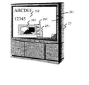
図36は、第4の実施形態における表示装置23上の表示画面の一例を示す図である。図36に示される表示装置23上には、電子化されたデータであるスキャン原稿261や、スキャン原稿261に含まれるGUI部品264、341等が表示されている。また、図36に示される表示装置23は、GUI部品表示切替ボタン361を備えており、例えばGUI部品表示切替ボタン361がユーザにより押下される等のGUI部品切替指示を受け取ると、GUI部品264、341等の表示・非表示を切替える。
FIG. 36 is a diagram illustrating an example of a display screen on the
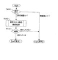
図37は、第4の実施形態における表示システムの全体処理の一例を示すフローチャートである。ステップS3701において、画像形成装置22及び表示装置23は、初期化処理を行い、操作画面を表示する等の初期化動作を行う。続いてステップS3702において、画像形成装置22及び表示装置23は、ユーザの操作(又はEvent)を受け付ける。
FIG. 37 is a flowchart illustrating an example of overall processing of the display system according to the fourth embodiment. In step S3701, the
続いてステップS3703において、画像形成装置22及び表示装置23は、Eventの判定を行う。画像形成装置22は、ユーザが、スキャン&表示指示を行ったと判定するとステップS3704に進む。また、表示装置23は、ユーザが、実行指示を行ったと判定するとステップS3707に進む。また、表示装置23は、ユーザが、GUI部品変更指示を行ったと判定するとステップS3708に進む。また、表示装置23は、ユーザが、GUI部品表示切替指示を行ったと判定すると、ステップS3709に進む。
Subsequently, in step S3703, the
ステップS3704では、画像形成装置22において手書きコマンドが書かれた原稿がスキャンされ、電子化されたデータとしてスキャン原稿を取得する。続いてステップS3705において、表示装置23は、スキャン原稿解釈処理を行い、例えばスキャン原稿中の手書きコマンドをGUI部品として解釈する。続いてステップS3706において表示装置23は、スキャン原稿表示処理を行い、手書きコマンドを除去したスキャン原稿と共にGUI部品を表示し、ステップS3702の処理に戻る。
In step S3704, the document on which the handwritten command is written is scanned in the
一方、ステップS3707では、表示装置23が、実行処理を行い、ユーザに指示されたメニュー項目やGUI部品に対応した処理を実行し、ステップS3702の処理に戻る。また、ステップS3708では、表示装置23が、GUI部品変更(又は置換)処理を行い、表示中のGUI部品を、指示されたGUI部品に変更し、ステップS3702の処理に戻る。また、ステップS3709では、表示装置23が、GUI部品表示切替処理を行い、GUI部品の表示・非表示の状態を切り替え、ステップS3702の処理に戻る。なお、GUI部品表示切替処理の詳細は、後述する図39に示す。
On the other hand, in step S3707, the
図38は、第4の実施形態におけるGUI部品データの一例を示す図である。GUI部品データは、GUI部品データを識別するIDと、GUI部品に対応する機能の情報と、相対表示位置及びサイズの情報と、対応するスキャン原稿を識別するスキャン原稿IDと、指示対象のオブジェクトの情報と、を含む。図38に示すGUI部品データは、データメモリ5に保持される。GUI部品データ382は、GUI部品データのIDとして「115」が記録され、指示対象に対する処理の機能として「次ページ」が記録され、相対表示位置及びサイズとして(60,85),(70,95)が記録されていることを表している。また、GUI部品データ382は、スキャン原稿IDとして「file021」(例えば、図36のスキャン原稿261に対応する)が記録され、指示対象として「スキャン原稿全体261」が記録されていることを表している。
FIG. 38 is a diagram illustrating an example of GUI component data according to the fourth embodiment. The GUI component data includes an ID for identifying the GUI component data, information on the function corresponding to the GUI component, information on the relative display position and size, a scan document ID for identifying the corresponding scan document, and the object to be designated. Information. The GUI component data shown in FIG. 38 is held in the data memory 5. In the
図39は、GUI部品表示切替処理の一例を示すフローチャートである。ステップS3901において、表示装置23は、現在のGUI部品の表示状態を判断する。表示装置23は、GUI部品を表示中であると判断すると、ステップS3902に進み、GUI部品を非表示中であると判断すると、ステップS3903に進む。
FIG. 39 is a flowchart illustrating an example of GUI component display switching processing. In step S3901, the
ステップS3902では、表示装置23が、GUI非表示処理を行い、表示中のGUI部品を非表示にし、GUI部品の表示切替処理を終了する。一方、ステップS3903では、表示装置23が、対応GUI部品取得処理を行い、表示装置23に表示中のスキャン原稿に対応したGUI部品を、図38に示したようなGUI部品データから検索して取得する。
In step S3902, the
続いてステップS3904において、表示装置23は、GUI部品表示処理を行い、ステップS3903において取得した全GUI部品を表示装置23上に表示し、GUI部品の表示切替処理を終了する。
Subsequently, in step S3904, the
なお、上述した説明では、表示装置23は、ユーザがGUI部品表示切替指示を行ったと判定すると、GUI部品の表示・非表示を切替えるよう説明を行った。しかしながら、表示装置23は、ユーザがGUI部品表示切替指示を行ったと判定すると、表示モードを切替えるようにしてもよい。そして、表示装置23は、表示モードを切り換えた以降のスキャン原稿表示処理では、表示モードに応じてGUI部品の表示・非表示を行うようにしてもよい。
In the above description, when the
上述したように、第4の実施形態によれば、表示装置23は、スキャン原稿と、対応するGUI部品と、を関連付けて格納、管理し、ユーザからの指示に基づいて、GUI部品の表示、非表示を行う。よって、必要なときだけGUI部品を表示させる等することが可能になるため、表示中の原稿データに対する操作性を向上させることができる。
As described above, according to the fourth embodiment, the
(第5の実施の形態)
以下、図40及び図41を用いて、表示装置23が、GUI部品に対応する処理の実行指示以外の処理を制限する例について説明する。画像形成装置22及び表示装置23を含む表示システムの構成は第1の実施の形態と同様であるので、その説明は省略する
(Fifth embodiment)
Hereinafter, an example in which the
図40は、第5の実施形態における表示装置23に表示された表示画面の一例を示す図である。表示装置23の表示画面上上には、電子化されたデータとしてのスキャン原稿261と、GUI部品264、341と、が表示されており、更に、メニューバー401が表示されている。また、図40は、メニューバー401からメニュー項目402のサブメニュー405が表示され、サブメニュー項目407の「印刷」処理がユーザにより選択されている例が示されている。
FIG. 40 is a diagram illustrating an example of a display screen displayed on the
図41は、実行許可判定処理の一例を示すフローチャートである。なお、図41に示す処理は、表示装置23の機能として、図4に示した実行部42が処理を行うものとして説明を行う。ステップS4101において、実行部42は、現在の実行モードを判断する。実行部42は、現在の実行モードが実行制限モードであると判断すると、ステップS4102に進み、制限無しモードであると判断すると、実行を許可し、実行許可判定処理を終了する。
FIG. 41 is a flowchart illustrating an example of the execution permission determination process. Note that the processing shown in FIG. 41 will be described on the assumption that the
ステップS4102では、実行部42が、表示中GUI部品検索処理を行い、例えば、ユーザがメニュー項目を用いて実行を指示した処理に対応するGUI部品が表示装置23に表示されているか否かを判定する。実行部42は、ユーザがメニュー項目を用いて実行を指示した処理に対応するGUI部品が表示装置23に表示されていると判定すると、処理の実行を許可し、実行許可判定処理を終了する。また、実行部42は、ユーザがメニュー項目を用いて実行を指示した処理に対応するGUI部品が表示装置23に表示されていないと判定すると、処理の実行を禁止し、実行許可判定処理を終了する。
In step S4102, the
上述したように、第5の実施形態によれば、表示装置23は、生成し、表示しているGUI部品に対応する処理の実行以外、処理の実行を禁止することができる。よって、誤動作等を防止し、表示中の原稿データに対する操作性を向上させることができる。また、誤動作を防止できるという意味で、安全を保障(セキュリティを向上)することができる。
As described above, according to the fifth embodiment, the
(第6の実施の形態)
以下、図42から図48を用いて、表示装置23が、手書きコマンドに関する動作内容等を特定し、手書きコマンドと関連付ける処理について説明する。
(Sixth embodiment)
Hereinafter, a process in which the
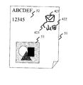
図42は、手書きコマンド及び手書き動作内容が記入されている原稿の一例を示す図である。図42に示される原稿51は、テキスト領域52と、画像領域53と、を含み、更に、手書きコマンド421、手書き動作内容422及び手書き関連付け指示423が記入されている。
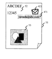
FIG. 42 is a diagram illustrating an example of a manuscript in which a handwriting command and handwriting operation content are entered. The
図43は、第6の実施形態における表示装置23上の表示画面の一例を示す図である。表示装置23上には図42に示した原稿51に対応する電子化されたデータとしてのスキャン原稿261が表示されている。また、表示装置23上には、図42の手書きコマンド421から生成された「送信」のGUI部品431と、図42の手書き動作内容422から生成された動作内容バルーンヘルプ432と、が表示されている。なお、GUI部品431と、動作内容バルーンヘルプ432と、は、図42の手書き関連付け指示423によって関連付けられている。なお、動作内容バルーンヘルプ432は、GUI部品431上にポインティングデバイスが位置したときに表示装置23が、表示するようにしてもよい。
FIG. 43 is a diagram illustrating an example of a display screen on the
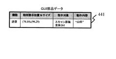
図44は、第6の実施形態における表示装置23に表示されたGUI部品のデータの一例を示す図である。GUI部品データは、GUI部品に対応する機能の情報と、相対表示位置及びサイズの情報と、指示対象のオブジェクトの情報と、GUI部品の動作内容と、を含む。図44に示すGUI部品データは、データメモリ5に保持される。例えばGUI部品データ441は、指示対象に対する処理の機能として「送信」が記録され、相対表示位置及びサイズとして(70,10),(90,25)が記録されていることを表している。また、GUI部品データ441は、指示対象として「スキャン原稿全体261」が記録され、処理の動作内容として「山田」が記録されていることを表している。つまり、GUI部品データ441に対応するGUI部品がユーザに押下等されると、実行部42は、GUI部品データ441に基づいて、スキャン原稿全体261を、山田に送信する。
FIG. 44 is a diagram illustrating an example of GUI component data displayed on the
図45は、動作内容特定処理の一例を示すフローチャートである。なお、図45に示す処理は、スキャン原稿解釈部49の、図4に示した動作内容特定部4dが処理を行うものとして説明を行う。
FIG. 45 is a flowchart illustrating an example of the operation content specifying process. The process shown in FIG. 45 will be described on the assumption that the operation
ステップS4501において、動作内容特定部4dは、文字認識処理を行い、スキャン原稿中の文字を認識する。続いてステップS4502において、動作内容特定部4dは、ステップS4501における文字認識が成功したか否かを判定する。動作内容特定部4dは、ステップS4501における文字認識が成功したと判定すると、ステップS4503に進む。また、動作内容特定部4dは、ステップS4501における文字認識が失敗したと判定すると、動作内容特定処理を終了する。
In step S4501, the operation
ステップS4503では、動作内容特定部4dが、対応データ抽出処理を行い、ステップS4501において認識した文字又は文字列に対応するデータ(例えば、図42の手書き動作内容422等)を、スキャン原稿から抽出し、動作内容特定処理を終了する。
In step S4503, the operation
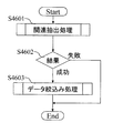
図46は、動作内容関連付け処理の一例を示すフローチャートである。なお、図46に示す処理は、スキャン原稿解釈部49の、図4に示した動作内容関連付け部4eが処理を行うものとして説明を行う。 FIG. 46 is a flowchart illustrating an example of the operation content association process. The processing shown in FIG. 46 will be described on the assumption that the operation content associating unit 4e shown in FIG.
ステップS4601において、動作内容関連付け部4eは、関連抽出処理を行い、スキャン原稿中の手書き関連付け指示(例えば、図42の手書き関連付け指示423)から手書きコマンドと、動作内容と、の関連付けに関する情報を抽出する。続いてステップS4602において、動作内容関連付け部4eは、ステップS4601における関連付けに関する情報の抽出が成功したか否かを判定する。動作内容関連付け部4eは、ステップS4601における関連付けに関する情報の抽出が成功したと判定すると、ステップS4603に進む。また、動作内容関連付け部4eは、ステップS4601における関連付けに関する情報の抽出が失敗したと判定すると、動作内容関連付け処理を終了する。
In step S4601, the action content associating unit 4e performs a relation extraction process, and extracts information related to the association between the handwritten command and the action content from the handwriting association instruction (for example, the
ステップS4603では、動作内容関連付け部4eが、データ絞込み処理を行い、ステップS4601において抽出した関連付けに関する情報から、手書きコマンドと、動作内容と、の組み合わせを絞り込む。 In step S4603, the action content associating unit 4e performs a data narrowing process to narrow down combinations of handwritten commands and action contents from the information related to the association extracted in step S4601.
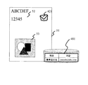
図47は、手書きコマンドが記入され、動作内容が電子透かしで埋め込まれた原稿の一例を示した図である。図47に示される原稿51は、テキスト領域52と、画像領域53と、を含み、更に、手書きコマンド421が記入され、電子透かし動作内容471が埋め込まれている。図4等には図示していないが、表示装置23は、その機能として、印刷を行う印刷部等を有し、例えば図47に示されるような原稿51を印刷、出力するようにしてもよい。又は画像形成装置22に印刷すべきデータを出力してもよい。
FIG. 47 is a diagram showing an example of a document in which a handwritten command is entered and the operation content is embedded with a digital watermark. The
また、原稿に、電子透かしで動作内容が埋め込まれていた場合、例えば動作内容特定部4d等は、上述した図45等の動作内容特定処理において、原稿に埋め込まれた電子透かしを認識し、認識した電子透かしから対応するデータを、スキャン原稿から抽出する。なお、ここで対応するデータとは、例えば図47の電子透かし動作内容471等である。
Also, when the operation content is embedded in the original with the digital watermark, for example, the operation
図48は、手書きコマンドが記入された原稿と、ユーザが、原稿又は手書きコマンドに対応させ入力部等を用いて動作内容を定義した定義データと、の一例を示す図である。図48に示される原稿51は、テキスト領域52と、画像領域53と、を含み、更に、手書きコマンド421が記入されている。ユーザは、図48に示されるような原稿51又は手書きコマンド421に対応させて、例えば原稿51を表示装置23に読み込ませる際に、動作内容を定義した定義データ481を、表示装置23に定義する。
FIG. 48 is a diagram illustrating an example of a manuscript in which a handwritten command is entered and definition data in which an operation content is defined by the user using an input unit or the like corresponding to the manuscript or the handwritten command. An original 51 shown in FIG. 48 includes a
上述したように、第6の実施形態によれば、表示装置23は、原稿に記入された手書きコマンドと、原稿に記入された手書き動作内容及び手書き関連付け指示と、に基づいて、手書きコマンド(又はGUI部品)と、動作内容と、を関連付ける。よって、表示中の原稿データに対する操作性を向上させることができる。
As described above, according to the sixth embodiment, the
また、第6の実施形態によれば、表示装置23は、原稿に記入された手書きコマンドと、電子透かしで埋め込まれた手書きコマンドに対する動作内容と、を関連付ける。よって、表示中の原稿データに対する操作性を向上させることができる。
Further, according to the sixth embodiment, the
また、第6の実施形態によれば、表示装置23は、原稿に記入された手書きコマンドと、入力部等を用いてユーザが動作内容を定義した定義データと、に基づいて、手書きコマンド(又はGUI部品)と、動作内容と、を関連付ける。よって、表示中の原稿データに対する操作性を向上させることができる。
Further, according to the sixth embodiment, the
(第7の実施の形態)
以下、図49から図51を用いて、表示装置23が、スキャン原稿上に記入された手書きコマンド以外のデータに基づいて、GUI部品を生成する処理について説明する。
(Seventh embodiment)
Hereinafter, a process in which the
図49は、デジタイザを備えた表示装置23上の表示画面の一例を示す図である。デジタイザ(座標入力装置)を用いた表示画面上のペン入力操作によって手書きコマンド491が記入されることで、上述した実施形態同様の動作が実現される。
FIG. 49 is a diagram showing an example of a display screen on the
図50は、マイクを備えた表示装置23上に表示された表示画面の一例を示す図である。マイク502を用いた音声入力操作によって音声コマンド501が記入されることで、上述した実施形態同様の動作が実現される。なお、上述した実施形態同様にGUI部品の相対表示位置や、サイズを表示装置23が特定するためには、ユーザは対応する指示を音声で行う必要がある。
FIG. 50 is a diagram illustrating an example of a display screen displayed on the
図51は、カメラを備えた表示装置23に表示された表示画面の一例を示す図である。カメラ512を用いた映像入力操作によってジェスチャコマンド511が記入されることで、上述した実施形態同様の動作が実現される。なお、上述した実施形態同様にGUI部品の表示位置や、サイズを表示装置23が特定するためには、ユーザは対応する指示をジェスチャで行う必要がある。
FIG. 51 is a diagram illustrating an example of a display screen displayed on the
上述したように、第7の実施形態によれば、表示装置23は、ペン入力操作等によって入力された手書きコマンドに基づいて、GUI部品を生成し、表示する等、上述した各実施の形態で示した処理を実行する。よって、表示中の原稿データに対する操作性を向上させることができる。
As described above, according to the seventh embodiment, the
また、第7の実施形態によれば、表示装置23は、マイク等を用いて入力された音声コマンドに基づいて、GUI部品を生成し、表示する等、上述した各実施の形態で示した処理を実行する。よって、表示中の原稿データに対する操作性を向上させることができる。
Further, according to the seventh embodiment, the
また、第7の実施形態によれば、表示装置23は、カメラ等を用いて入力されたジェスチャコマンドに基づいて、GUI部品を生成し、表示する等、上述した各実施の形態で示した処理を実行する。よって、表示中の原稿データに対する操作性を向上させることができる。
Further, according to the seventh embodiment, the
以上、上述したように、本発明の実施の形態によれば、表示中の原稿データに対する操作性を向上させることができる。 As described above, according to the embodiment of the present invention, the operability with respect to the document data being displayed can be improved.
以上、本発明の好ましい実施の形態について詳述したが、本発明は係る特定の実施の形態に限定されるものではなく、特許請求の範囲に記載された本発明の要旨の範囲内において、種々の変形・変更が可能である。 The preferred embodiment of the present invention has been described in detail above, but the present invention is not limited to the specific embodiment, and various modifications can be made within the scope of the gist of the present invention described in the claims. Can be modified or changed.
例えば、本発明は、複数の機器(例えばディスプレイ及び複合機等)から構成されるシステムに適用してもよい。また、本発明は、一つの機器からなる装置(例えば、スキャナ機能を有したディスプレイ、又はディスプレイのような表示装置を有した複合機、又はスキャン原稿を、タッチパネル上等に表示可能な複合機等)に適用してもよい。 For example, the present invention may be applied to a system composed of a plurality of devices (for example, a display and a multifunction device). The present invention also relates to a device comprising a single device (for example, a display having a scanner function, or a multifunction device having a display device such as a display, or a multifunction device capable of displaying a scanned document on a touch panel, etc. ).
1 入力部
2 CPU
3 出力部
4 プログラムメモリ
5 データメモリ
6 バス
41 スキャン&表示部
42 実行部
43 GUI部品変更部
44 スキャン原稿
45 除去後のスキャン原稿
46 GUI部品
47 実行可能処理定義データ
1 Input unit 2 CPU
3 Output unit 4 Program memory 5 Data memory 6
Claims (6)
前記GUI部品の表示位置と前記オブジェクトの表示位置とに基づいて、前記GUI部品と前記オブジェクトとが重なっているかを判定する判定手段と、
前記GUI部品と前記オブジェクトとが重なっていると判定された場合は、前記GUI部品に対する操作を受け付けると前記オブジェクトに対する処理を実行する実行手段と、
を有することを特徴とする情報処理装置。 A display position of a GUI component corresponding to the handwriting command on a display screen of a paper document obtained by scanning a paper document including a handwriting command and an image area, and display of an object corresponding to the image area on the display screen An acquisition means for acquiring a position;
Determining means for determining whether the GUI component and the object overlap, based on the display position of the GUI component and the display position of the object;
If said GUI parts and the object is determined to overlap, and accepts an operation to the GUI component and executing means to execute the processing for the object,
An information processing apparatus comprising:
前記第2の判定手段で、前記機能が、前記オブジェクトに対して有効であると判定されなかった場合、前記実行手段は、前記GUI部品に対する操作を受け付けても前記オブジェクトに対する処理を実行しないことを特徴とする請求項1に記載の情報処理装置。 A second determination unit that determines whether the function of the GUI component is valid for the object;
In the second determination means, the function, if it is not determined to be valid with respect to said object, said executing means includes: a This also accepts an operation for the GUI component not perform processing for the object The information processing apparatus according to claim 1.
手書きコマンドと画像領域とを含む紙の原稿をスキャンして得たスキャン原稿から、前記手書きコマンドに対応するGUI部品の表示画面における表示位置と、前記画像領域に対応するオブジェクトの前記表示画面における表示位置と、を取得する取得ステップと、 A display position of a GUI component corresponding to the handwriting command on a display screen of a paper document obtained by scanning a paper document including a handwriting command and an image area, and display of an object corresponding to the image area on the display screen An acquisition step for acquiring a position;
前記GUI部品の表示位置と前記オブジェクトの表示位置とに基づいて、前記GUI部品と前記オブジェクトとが重なっているかを判定する判定ステップと、 A determination step of determining whether the GUI component and the object overlap based on the display position of the GUI component and the display position of the object;
前記GUI部品と前記オブジェクトとが重なっていると判定された場合は、前記GUI部品に対する操作を受け付けると前記オブジェクトに対する処理を実行する実行ステップと、 If it is determined that the GUI component and the object overlap, an execution step of executing a process on the object upon receiving an operation on the GUI component;
を含むことを特徴とする情報処理方法。An information processing method comprising:
手書きコマンドと画像領域とを含む紙の原稿をスキャンして得たスキャン原稿から、前記手書きコマンドに対応するGUI部品の表示画面における表示位置と、前記画像領域に対応するオブジェクトの前記表示画面における表示位置と、を取得する取得ステップと、 A display position of a GUI component corresponding to the handwriting command on a display screen of a paper document obtained by scanning a paper document including a handwriting command and an image area, and display of an object corresponding to the image area on the display screen An acquisition step for acquiring a position;
前記GUI部品の表示位置と前記オブジェクトの表示位置とに基づいて、前記GUI部品と前記オブジェクトとが重なっているかを判定する判定ステップと、 A determination step of determining whether the GUI component and the object overlap based on the display position of the GUI component and the display position of the object;
前記GUI部品と前記オブジェクトとが重なっていると判定された場合は、前記GUI部品に対する操作を受け付けると前記オブジェクトに対する処理を実行する実行ステップと、 If it is determined that the GUI component and the object overlap, an execution step of executing a process on the object upon receiving an operation on the GUI component;
を実行させることを特徴とするプログラム。A program characterized by having executed.
Priority Applications (3)
| Application Number | Priority Date | Filing Date | Title |
|---|---|---|---|
| JP2005261126A JP4741908B2 (en) | 2005-09-08 | 2005-09-08 | Information processing apparatus and information processing method |
| US11/465,201 US7904837B2 (en) | 2005-09-08 | 2006-08-17 | Information processing apparatus and GUI component display method for performing display operation on document data |
| CNB2006101277981A CN100456282C (en) | 2005-09-08 | 2006-09-08 | Information processing apparatus and GUI component display method for performing display operation on document data |
Applications Claiming Priority (1)
| Application Number | Priority Date | Filing Date | Title |
|---|---|---|---|
| JP2005261126A JP4741908B2 (en) | 2005-09-08 | 2005-09-08 | Information processing apparatus and information processing method |
Publications (3)
| Publication Number | Publication Date |
|---|---|
| JP2007072901A JP2007072901A (en) | 2007-03-22 |
| JP2007072901A5 JP2007072901A5 (en) | 2008-10-16 |
| JP4741908B2 true JP4741908B2 (en) | 2011-08-10 |
Family
ID=37829605
Family Applications (1)
| Application Number | Title | Priority Date | Filing Date |
|---|---|---|---|
| JP2005261126A Expired - Fee Related JP4741908B2 (en) | 2005-09-08 | 2005-09-08 | Information processing apparatus and information processing method |
Country Status (3)
| Country | Link |
|---|---|
| US (1) | US7904837B2 (en) |
| JP (1) | JP4741908B2 (en) |
| CN (1) | CN100456282C (en) |
Families Citing this family (24)
| Publication number | Priority date | Publication date | Assignee | Title |
|---|---|---|---|---|
| JP2007511814A (en) * | 2003-10-15 | 2007-05-10 | コーニンクレッカ フィリップス エレクトロニクス エヌ ヴィ | Automatic generation of user interface descriptions through drawings |
| WO2006087824A1 (en) * | 2005-02-17 | 2006-08-24 | Hitachi, Ltd. | Information management system and document information management method |
| USD560681S1 (en) * | 2006-03-31 | 2008-01-29 | Microsoft Corporation | Icon for a portion of a display screen |
| JP5214277B2 (en) * | 2008-02-29 | 2013-06-19 | 卓雄 田中 | Medical diagnosis support system |
| KR101509245B1 (en) * | 2008-07-31 | 2015-04-08 | 삼성전자주식회사 | User interface apparatus and method using pattern recognition in portable terminal |
| JP5459046B2 (en) * | 2010-04-27 | 2014-04-02 | ソニー株式会社 | Information processing apparatus, information processing method, program, and information processing system |
| JP5589537B2 (en) * | 2010-04-30 | 2014-09-17 | ソニー株式会社 | Information processing apparatus, information processing method, program, information providing apparatus, and information processing system |
| JP5240876B2 (en) * | 2011-07-12 | 2013-07-17 | 卓雄 田中 | Medical diagnosis support system |
| CN104137026B (en) | 2011-12-30 | 2017-05-10 | 英特尔公司 | Method, device and system for cartographic recognition |
| US20150131913A1 (en) * | 2011-12-30 | 2015-05-14 | Glen J. Anderson | Interactive drawing recognition using status determination |
| US20130207901A1 (en) * | 2012-02-10 | 2013-08-15 | Nokia Corporation | Virtual Created Input Object |
| CN102799367B (en) * | 2012-06-29 | 2015-05-13 | 鸿富锦精密工业(深圳)有限公司 | Electronic device and touch control method thereof |
| KR102203885B1 (en) * | 2013-04-26 | 2021-01-15 | 삼성전자주식회사 | User terminal device and control method thereof |
| KR102063103B1 (en) * | 2013-08-23 | 2020-01-07 | 엘지전자 주식회사 | Mobile terminal |
| US10474886B2 (en) * | 2014-08-13 | 2019-11-12 | Rakuten, Inc. | Motion input system, motion input method and program |
| KR20170014764A (en) * | 2015-07-31 | 2017-02-08 | 삼성전자주식회사 | Screen controlling method and electronic device supporting the same |
| US10228775B2 (en) * | 2016-01-22 | 2019-03-12 | Microsoft Technology Licensing, Llc | Cross application digital ink repository |
| KR102544578B1 (en) * | 2016-03-07 | 2023-06-15 | 엘에스일렉트릭(주) | Controlling method of data display apparatus |
| US9946698B2 (en) * | 2016-03-31 | 2018-04-17 | Konica Minolta Laboratory U.S.A., Inc. | Inserting text and graphics using hand markup |
| CN112654285B (en) * | 2018-09-25 | 2024-10-11 | 富士胶片株式会社 | Medical image display device, method and recording medium |
| WO2020067256A1 (en) * | 2018-09-28 | 2020-04-02 | 日本電産株式会社 | Control device |
| US11551480B2 (en) * | 2019-04-11 | 2023-01-10 | Ricoh Company, Ltd. | Handwriting input apparatus, handwriting input method, program, and input system |
| US10764448B1 (en) * | 2019-04-24 | 2020-09-01 | Kyocera Document Solutions Inc. | Information processing apparatus and image forming apparatus performing file conversion of handwriting comment and comment extraction method |
| JP7682706B2 (en) * | 2021-06-11 | 2025-05-26 | キヤノン株式会社 | PROGRAM, INFORMATION PROCESSING APPARATUS, AND METHOD FOR CONTROLLING INFORMATION PROCESSING APPARATUS |
Family Cites Families (18)
| Publication number | Priority date | Publication date | Assignee | Title |
|---|---|---|---|---|
| TW198107B (en) * | 1991-02-28 | 1993-01-11 | Ibm | |
| EP0610581A3 (en) * | 1993-01-29 | 1994-12-28 | Ibm | Visualization tool for graphical display of trace data produced by a parallel processing computer. |
| US6208336B1 (en) * | 1998-03-20 | 2001-03-27 | Sun Microsystems, Inc. | Dynamic graphical user interface feature-set configuration |
| EP1182503A1 (en) * | 2000-08-17 | 2002-02-27 | Eastman Kodak Company | A kit for use in organizing images |
| US6745186B1 (en) * | 2000-08-17 | 2004-06-01 | Eastman Kodak Company | Product and method for organizing and searching digital images |
| US7058902B2 (en) * | 2002-07-30 | 2006-06-06 | Microsoft Corporation | Enhanced on-object context menus |
| CN100507902C (en) | 2003-02-27 | 2009-07-01 | 无敌科技股份有限公司 | System and method for generating graphics and animation by using vector graphics component |
| US7886236B2 (en) * | 2003-03-28 | 2011-02-08 | Microsoft Corporation | Dynamic feedback for gestures |
| JP2004342024A (en) | 2003-05-19 | 2004-12-02 | Canon Inc | Pen-type pointing device and image input device |
| JP2005079771A (en) * | 2003-08-29 | 2005-03-24 | Konica Minolta Medical & Graphic Inc | Image output system, image output device, image output method, program, and storage medium stored with the program |
| JP2007511814A (en) * | 2003-10-15 | 2007-05-10 | コーニンクレッカ フィリップス エレクトロニクス エヌ ヴィ | Automatic generation of user interface descriptions through drawings |
| US7717712B2 (en) * | 2003-12-19 | 2010-05-18 | Xerox Corporation | Method and apparatus for language learning via controlled text authoring |
| US7707039B2 (en) * | 2004-02-15 | 2010-04-27 | Exbiblio B.V. | Automatic modification of web pages |
| US7831933B2 (en) * | 2004-03-17 | 2010-11-09 | Leapfrog Enterprises, Inc. | Method and system for implementing a user interface for a device employing written graphical elements |
| JP2006277167A (en) * | 2005-03-29 | 2006-10-12 | Fuji Xerox Co Ltd | Annotation data processing program, system and method |
| US7526129B2 (en) * | 2005-06-23 | 2009-04-28 | Microsoft Corporation | Lifting ink annotations from paper |
| JP2007102545A (en) * | 2005-10-05 | 2007-04-19 | Ricoh Co Ltd | Electronic document creation apparatus, electronic document creation method, and electronic document creation program |
| JP2007109118A (en) * | 2005-10-17 | 2007-04-26 | Hitachi Ltd | Input instruction processing apparatus and input instruction processing program |
-
2005
- 2005-09-08 JP JP2005261126A patent/JP4741908B2/en not_active Expired - Fee Related
-
2006
- 2006-08-17 US US11/465,201 patent/US7904837B2/en not_active Expired - Fee Related
- 2006-09-08 CN CNB2006101277981A patent/CN100456282C/en not_active Expired - Fee Related
Also Published As
| Publication number | Publication date |
|---|---|
| US20070052685A1 (en) | 2007-03-08 |
| JP2007072901A (en) | 2007-03-22 |
| CN100456282C (en) | 2009-01-28 |
| US7904837B2 (en) | 2011-03-08 |
| CN1928851A (en) | 2007-03-14 |
Similar Documents
| Publication | Publication Date | Title |
|---|---|---|
| JP4741908B2 (en) | Information processing apparatus and information processing method | |
| JP5001182B2 (en) | Display control apparatus, electronic device, display control method, and program | |
| KR920001696B1 (en) | Data processing unit equipped with multi window display control unit | |
| US8400476B2 (en) | Display device, method and program | |
| JP5911326B2 (en) | Information processing apparatus, information processing apparatus control method, and program | |
| JP5889028B2 (en) | Moving picture recording apparatus, control method therefor, computer program, and storage medium | |
| JP2014026629A (en) | Input device and input support method | |
| KR100703771B1 (en) | Apparatus and method for displaying a character input panel | |
| US10684772B2 (en) | Document viewing apparatus and program | |
| JP5388385B2 (en) | Display control apparatus, display control method, and program | |
| JP5523119B2 (en) | Display control apparatus and display control method | |
| JP5589309B2 (en) | Display control apparatus, image processing apparatus, and program | |
| JP2009188942A (en) | Image display device, image display method, and program | |
| JP6327969B2 (en) | Information processing apparatus, information processing method, and program | |
| JP2008152585A (en) | Display image control apparatus and control method thereof | |
| JP5414920B2 (en) | Display control apparatus, display control method, and program | |
| JP6376953B2 (en) | INFORMATION PROCESSING APPARATUS, CONTROL METHOD THEREOF, COMPUTER PROGRAM, AND STORAGE MEDIUM | |
| JP2014160416A (en) | Browsing system and program | |
| JP2013182329A (en) | Information processing device, control method for information processing device, and program | |
| JP5213794B2 (en) | Information processing apparatus and information processing method | |
| JP5943743B2 (en) | Display control apparatus, control method thereof, and program | |
| KR102592620B1 (en) | Chinese text input method and apparatus for mobile device | |
| JP2014197256A (en) | Editing device, editing method, and program | |
| US20180095391A1 (en) | Image Display Apparatus, and Method and Computer-Readable Medium for the Same | |
| JP5762502B2 (en) | Display control apparatus and display control method |
Legal Events
| Date | Code | Title | Description |
|---|---|---|---|
| A521 | Request for written amendment filed |
Free format text: JAPANESE INTERMEDIATE CODE: A523 Effective date: 20080829 |
|
| A621 | Written request for application examination |
Free format text: JAPANESE INTERMEDIATE CODE: A621 Effective date: 20080829 |
|
| A977 | Report on retrieval |
Free format text: JAPANESE INTERMEDIATE CODE: A971007 Effective date: 20101111 |
|
| A131 | Notification of reasons for refusal |
Free format text: JAPANESE INTERMEDIATE CODE: A131 Effective date: 20101130 |
|
| A521 | Request for written amendment filed |
Free format text: JAPANESE INTERMEDIATE CODE: A523 Effective date: 20110127 |
|
| A01 | Written decision to grant a patent or to grant a registration (utility model) |
Free format text: JAPANESE INTERMEDIATE CODE: A01 Effective date: 20110426 |
|
| A01 | Written decision to grant a patent or to grant a registration (utility model) |
Free format text: JAPANESE INTERMEDIATE CODE: A01 |
|
| A61 | First payment of annual fees (during grant procedure) |
Free format text: JAPANESE INTERMEDIATE CODE: A61 Effective date: 20110509 |
|
| R150 | Certificate of patent or registration of utility model |
Free format text: JAPANESE INTERMEDIATE CODE: R150 |
|
| FPAY | Renewal fee payment (event date is renewal date of database) |
Free format text: PAYMENT UNTIL: 20140513 Year of fee payment: 3 |
|
| LAPS | Cancellation because of no payment of annual fees |