JP4741232B2 - Curable adhesive article having topographic features - Google Patents
Curable adhesive article having topographic features Download PDFInfo
- Publication number
- JP4741232B2 JP4741232B2 JP2004508198A JP2004508198A JP4741232B2 JP 4741232 B2 JP4741232 B2 JP 4741232B2 JP 2004508198 A JP2004508198 A JP 2004508198A JP 2004508198 A JP2004508198 A JP 2004508198A JP 4741232 B2 JP4741232 B2 JP 4741232B2
- Authority
- JP
- Japan
- Prior art keywords
- adhesive layer
- curable adhesive
- adhesive
- curable
- present
- Prior art date
- Legal status (The legal status is an assumption and is not a legal conclusion. Google has not performed a legal analysis and makes no representation as to the accuracy of the status listed.)
- Expired - Fee Related
Links
Images


Classifications
-
- C—CHEMISTRY; METALLURGY
- C09—DYES; PAINTS; POLISHES; NATURAL RESINS; ADHESIVES; COMPOSITIONS NOT OTHERWISE PROVIDED FOR; APPLICATIONS OF MATERIALS NOT OTHERWISE PROVIDED FOR
- C09J—ADHESIVES; NON-MECHANICAL ASPECTS OF ADHESIVE PROCESSES IN GENERAL; ADHESIVE PROCESSES NOT PROVIDED FOR ELSEWHERE; USE OF MATERIALS AS ADHESIVES
- C09J7/00—Adhesives in the form of films or foils
- C09J7/30—Adhesives in the form of films or foils characterised by the adhesive composition
- C09J7/38—Pressure-sensitive adhesives [PSA]
-
- C—CHEMISTRY; METALLURGY
- C09—DYES; PAINTS; POLISHES; NATURAL RESINS; ADHESIVES; COMPOSITIONS NOT OTHERWISE PROVIDED FOR; APPLICATIONS OF MATERIALS NOT OTHERWISE PROVIDED FOR
- C09J—ADHESIVES; NON-MECHANICAL ASPECTS OF ADHESIVE PROCESSES IN GENERAL; ADHESIVE PROCESSES NOT PROVIDED FOR ELSEWHERE; USE OF MATERIALS AS ADHESIVES
- C09J7/00—Adhesives in the form of films or foils
- C09J7/10—Adhesives in the form of films or foils without carriers
-
- C—CHEMISTRY; METALLURGY
- C09—DYES; PAINTS; POLISHES; NATURAL RESINS; ADHESIVES; COMPOSITIONS NOT OTHERWISE PROVIDED FOR; APPLICATIONS OF MATERIALS NOT OTHERWISE PROVIDED FOR
- C09J—ADHESIVES; NON-MECHANICAL ASPECTS OF ADHESIVE PROCESSES IN GENERAL; ADHESIVE PROCESSES NOT PROVIDED FOR ELSEWHERE; USE OF MATERIALS AS ADHESIVES
- C09J7/00—Adhesives in the form of films or foils
- C09J7/30—Adhesives in the form of films or foils characterised by the adhesive composition
- C09J7/35—Heat-activated
-
- C—CHEMISTRY; METALLURGY
- C09—DYES; PAINTS; POLISHES; NATURAL RESINS; ADHESIVES; COMPOSITIONS NOT OTHERWISE PROVIDED FOR; APPLICATIONS OF MATERIALS NOT OTHERWISE PROVIDED FOR
- C09J—ADHESIVES; NON-MECHANICAL ASPECTS OF ADHESIVE PROCESSES IN GENERAL; ADHESIVE PROCESSES NOT PROVIDED FOR ELSEWHERE; USE OF MATERIALS AS ADHESIVES
- C09J2301/00—Additional features of adhesives in the form of films or foils
- C09J2301/20—Additional features of adhesives in the form of films or foils characterized by the structural features of the adhesive itself
- C09J2301/204—Additional features of adhesives in the form of films or foils characterized by the structural features of the adhesive itself the adhesive coating being discontinuous
-
- C—CHEMISTRY; METALLURGY
- C09—DYES; PAINTS; POLISHES; NATURAL RESINS; ADHESIVES; COMPOSITIONS NOT OTHERWISE PROVIDED FOR; APPLICATIONS OF MATERIALS NOT OTHERWISE PROVIDED FOR
- C09J—ADHESIVES; NON-MECHANICAL ASPECTS OF ADHESIVE PROCESSES IN GENERAL; ADHESIVE PROCESSES NOT PROVIDED FOR ELSEWHERE; USE OF MATERIALS AS ADHESIVES
- C09J2301/00—Additional features of adhesives in the form of films or foils
- C09J2301/20—Additional features of adhesives in the form of films or foils characterized by the structural features of the adhesive itself
- C09J2301/206—Additional features of adhesives in the form of films or foils characterized by the structural features of the adhesive itself the adhesive layer comprising non-adhesive protrusions
-
- C—CHEMISTRY; METALLURGY
- C09—DYES; PAINTS; POLISHES; NATURAL RESINS; ADHESIVES; COMPOSITIONS NOT OTHERWISE PROVIDED FOR; APPLICATIONS OF MATERIALS NOT OTHERWISE PROVIDED FOR
- C09J—ADHESIVES; NON-MECHANICAL ASPECTS OF ADHESIVE PROCESSES IN GENERAL; ADHESIVE PROCESSES NOT PROVIDED FOR ELSEWHERE; USE OF MATERIALS AS ADHESIVES
- C09J2301/00—Additional features of adhesives in the form of films or foils
- C09J2301/20—Additional features of adhesives in the form of films or foils characterized by the structural features of the adhesive itself
- C09J2301/208—Additional features of adhesives in the form of films or foils characterized by the structural features of the adhesive itself the adhesive layer being constituted by at least two or more adjacent or superposed adhesive layers, e.g. multilayer adhesive
-
- C—CHEMISTRY; METALLURGY
- C09—DYES; PAINTS; POLISHES; NATURAL RESINS; ADHESIVES; COMPOSITIONS NOT OTHERWISE PROVIDED FOR; APPLICATIONS OF MATERIALS NOT OTHERWISE PROVIDED FOR
- C09J—ADHESIVES; NON-MECHANICAL ASPECTS OF ADHESIVE PROCESSES IN GENERAL; ADHESIVE PROCESSES NOT PROVIDED FOR ELSEWHERE; USE OF MATERIALS AS ADHESIVES
- C09J2301/00—Additional features of adhesives in the form of films or foils
- C09J2301/40—Additional features of adhesives in the form of films or foils characterized by the presence of essential components
- C09J2301/412—Additional features of adhesives in the form of films or foils characterized by the presence of essential components presence of microspheres
-
- C—CHEMISTRY; METALLURGY
- C09—DYES; PAINTS; POLISHES; NATURAL RESINS; ADHESIVES; COMPOSITIONS NOT OTHERWISE PROVIDED FOR; APPLICATIONS OF MATERIALS NOT OTHERWISE PROVIDED FOR
- C09J—ADHESIVES; NON-MECHANICAL ASPECTS OF ADHESIVE PROCESSES IN GENERAL; ADHESIVE PROCESSES NOT PROVIDED FOR ELSEWHERE; USE OF MATERIALS AS ADHESIVES
- C09J2433/00—Presence of (meth)acrylic polymer
-
- C—CHEMISTRY; METALLURGY
- C09—DYES; PAINTS; POLISHES; NATURAL RESINS; ADHESIVES; COMPOSITIONS NOT OTHERWISE PROVIDED FOR; APPLICATIONS OF MATERIALS NOT OTHERWISE PROVIDED FOR
- C09J—ADHESIVES; NON-MECHANICAL ASPECTS OF ADHESIVE PROCESSES IN GENERAL; ADHESIVE PROCESSES NOT PROVIDED FOR ELSEWHERE; USE OF MATERIALS AS ADHESIVES
- C09J2463/00—Presence of epoxy resin
Abstract
Description
本発明は、硬化性接着物品、および硬化性接着物品の製造方法に関する。 The present invention relates to a curable adhesive article and a method for producing a curable adhesive article.
感圧接着剤(PSA)は、室温における粘着性、最小量の接着圧力を使用する接着性、接着強度、および適用の容易さなどの望ましい特性のため、種々の用途で使用されている。しかし、ある用途においては、PSAでは必要な接着剤層の性質が得られない。たとえば、「ガス放出性材料」であり接着が困難であることが知られているアクリルシートおよびポリカーボネートシートに従来のPSAを適用すると、気泡および層間剥離が生じることがある。さらに、従来のPSAは経時によって流動し、および/またはPSA層内部に存在するミクロ構造および/またはマクロ構造などのあらゆる構造的またはトポグラフィー的特徴が高温および/または圧力に曝露することによって失われてしまう。 Pressure sensitive adhesives (PSAs) are used in a variety of applications because of desirable properties such as tack at room temperature, adhesion using minimal amounts of adhesive pressure, adhesive strength, and ease of application. However, for some applications, PSA does not provide the necessary adhesive layer properties. For example, when conventional PSA is applied to acrylic and polycarbonate sheets that are “gas releasing materials” and are known to be difficult to bond, air bubbles and delamination may occur. Furthermore, conventional PSA flows over time and / or is lost by exposure to high temperatures and / or pressures of any structural or topographic features such as microstructures and / or macrostructures present within the PSA layer. End up.
硬化性接着剤(たとえば熱または光で硬化)も多数の用途で使用されている。硬化性接着剤は、実質的に永続的で高強度の接着性などの多数の望ましい特性を有するが、従来の硬化性接着剤は、初期粘着性などの上述のPSAの望ましい性質を有していない。 Curable adhesives (eg, cured with heat or light) are also used in many applications. While curable adhesives have a number of desirable properties such as substantially permanent and high strength adhesion, conventional curable adhesives have the desirable properties of the PSA described above, such as initial tack. Absent.
本発明は、構造的またはトポグラフィー的特徴、硬化前および少なくとも部分的に硬化させた後の感圧接着性、高温に曝露場合でさえも存在する流動抵抗性を有する硬化性接着剤層に関する。この硬化性接着剤層は、1つ以上の基材への接着前および接着後にその構造的またはトポグラフィー的特徴の少なくとも一部を維持する。硬化性接着剤層は、1つ以上の基材への接着前および接着中に所望の程度の粘着性を有し、硬化させて永続的なトポグラフィー的特徴を内部に有する構造的接着剤層を形成することができる。本発明の例示的な一実施態様においては、硬化性接着剤層は、硬化性接着剤層の第1の最外面の少なくとも一部を形成する複数のミクロ構造またはマクロ構造を含み、硬化性接着剤層の第1の最外面は、(i)基材に接着するのに十分な粘着性を有し、(ii)約37.8℃(100°F)を超える温度に曝露した場合に初期構造化表面プロファイルが実質的に維持されるような構造状態に硬化する。 The present invention relates to a curable adhesive layer having structural or topographic features, pressure sensitive adhesion before and after at least partial curing, and flow resistance that exists even when exposed to high temperatures. The curable adhesive layer maintains at least some of its structural or topographic features before and after bonding to one or more substrates. A curable adhesive layer is a structural adhesive layer that has a desired degree of tack before and during adhesion to one or more substrates and is cured to have permanent topographic features therein Can be formed. In an exemplary embodiment of the invention, the curable adhesive layer includes a plurality of microstructures or macrostructures that form at least a portion of the first outermost surface of the curable adhesive layer, and the curable adhesive layer The first outermost surface of the agent layer is (i) sufficiently tacky to adhere to the substrate and (ii) initial when exposed to a temperature greater than about 37.8 ° C. (100 ° F.). Cured to a structural state such that the structured surface profile is substantially maintained.
本発明は、1つ以上の硬化性接着剤層と、場合によっては、1つ以上の追加層とを含む硬化性接着物品にも関する。本発明の例示的な一実施態様においては、この製造品は、(a)硬化性接着剤層であって、硬化性接着剤層の第1の最外面の少なくとも一部を形成する複数のミクロ構造またはマクロ構造を有し、(i)基材に接着するのに十分な粘着性を有し、(ii)約37.8℃(100°F)を超える温度に曝露した場合に初期構造化表面プロファイルが実質的に維持されるような構造状態に硬化する硬化性接着剤層と、(b)硬化性接着剤層の最外面上の少なくとも1つの追加層とを含む。例示的な硬化性接着物品は、限定するものではないが、たとえば、感圧接着剤層などの第2の接着剤層、少なくとも1つのミクロ構造化またはマクロ構造化剥離ライナー、少なくとも1つの非接着性基材層、あるいはそれらのあらゆる組み合わせなどの他の層をさらに含むことができる。 The present invention also relates to a curable adhesive article that includes one or more curable adhesive layers and, optionally, one or more additional layers. In an exemplary embodiment of the invention, the article of manufacture comprises: (a) a curable adhesive layer comprising a plurality of micros forming at least a portion of the first outermost surface of the curable adhesive layer. Having a structure or macrostructure, (i) having sufficient tack to adhere to a substrate, and (ii) initial structuring when exposed to temperatures greater than about 37.8 ° C (100 ° F) A curable adhesive layer that cures to a structural state such that the surface profile is substantially maintained, and (b) at least one additional layer on the outermost surface of the curable adhesive layer. Exemplary curable adhesive articles include, but are not limited to, a second adhesive layer, such as, for example, a pressure sensitive adhesive layer, at least one microstructured or macrostructured release liner, at least one non-adhesive. Other layers, such as a conductive substrate layer, or any combination thereof may further be included.
さらに本発明は、硬化性接着剤層およびそれを含む物品の製造方法にも関する。本発明の例示的な一実施態様においては、硬化性接着物品は、ミクロ構造化またはマクロ構造化剥離ライナー上にコーティングして、剥離ライナーと接触した硬化性接着剤の第1の最外面の少なくとも一部の上に複数のミクロ構造またはマクロ構造を有する硬化性接着剤層を形成するステップを含む方法によって製造され、硬化性接着剤層の第1の最外面は、(i)基材に接着するのに十分な粘着性を有し、(ii)約37.8℃(100°F)を超える温度に曝露した場合に初期構造化表面プロファイルが実質的に維持されるような構造状態に硬化する。 The present invention further relates to a curable adhesive layer and a method for producing an article comprising the same. In one exemplary embodiment of the present invention, the curable adhesive article is coated on a microstructured or macrostructured release liner to provide at least a first outermost surface of the curable adhesive in contact with the release liner. Manufactured by a method comprising forming a curable adhesive layer having a plurality of microstructures or macrostructures on a portion, wherein the first outermost surface of the curable adhesive layer is bonded to a substrate (i) (Ii) cure to a structural state such that the initial structured surface profile is substantially maintained when exposed to temperatures in excess of about 37.8 ° C. (100 ° F.). To do.
本発明のさらに別の例示的な実施態様においては、硬化性接着剤層および物品が、硬化性接着剤のエンボス加工可能層を形成するステップと、エンボス加工可能層の少なくとも1つの外面をミクロ構造化またはマクロ構造化剥離ライナーまたは工具でエンボス加工して、剥離ライナーと接触した硬化性接着剤の第1の最外面の少なくとも一部の上に複数のミクロ構造またはマクロ構造を有する硬化性接着剤層を形成するステップとを含む方法によって形成され、硬化性接着剤層の第1の最外面は、(i)基材に接着するのに十分な粘着性を有し、(ii)約37.8℃(100°F)を超える温度に曝露した場合に初期構造化表面プロファイルが実質的に維持されるような構造状態に硬化する。 In yet another exemplary embodiment of the present invention, the curable adhesive layer and the article form an embossable layer of the curable adhesive, and at least one outer surface of the embossable layer is microstructured. A curable adhesive having a plurality of microstructures or macrostructures on at least a portion of the first outermost surface of the curable adhesive in contact with the release liner, embossed with a structured or macrostructured release liner or tool Forming a layer, wherein the first outermost surface of the curable adhesive layer has (i) sufficient tack to adhere to the substrate, and (ii) about 37. Cured to a structural state such that the initial structured surface profile is substantially maintained when exposed to temperatures in excess of 8 ° C. (100 ° F.).
本発明のこれらおよびその他の特徴および利点は、以下の開示される実施態様の詳細な説明および添付の請求項を検討すれば明らかになるであろう。 These and other features and advantages of the present invention will become apparent upon review of the following detailed description of the disclosed embodiments and the appended claims.
添付の図面を参照しながら本発明をさらに説明する。 The invention will be further described with reference to the accompanying drawings.
本発明は、(i)基材に接着するのに十分な粘着性を有し、(ii)約37.8℃(100°F)を超える温度に曝露した場合に初期構造化表面プロファイルが実質的に維持されるような構造状態に硬化する、ミクロ構造化またはマクロ構造化接着剤に関する。ミクロ構造化またはマクロ構造化接着剤は、積層工程中および最終製品中でもそれらのトポグラフィー的特徴を実質的に維持する。積層工程中、接着剤のトポグラフィー的特徴は、接着剤を基材に接着するために圧力が加えられる場合にある程度変形することができる。トポグラフィー的特徴の変形が積層中に起こる場合、その変形した特徴が最終製品中で実質的に維持される。最終製品中の接着剤のトポグラフィー的特徴は、その製品の外面上に存在することができる。そのような場合、接着剤のトポグラフィー的特徴の外観は、硬化前後でほぼ類似した構造となることができ、たとえば、同じ全体的形状および寸法を有することができる。別の基材がトポグラフィー的特徴に積層される場合、トポグラフィー的特徴が積層の圧力によって変形する場合があり、たとえば、トポグラフィー的特徴上の先端部の平坦化、および/または個々の特徴の接触面積の増加が発生しうる。 The present invention provides: (i) having sufficient tack to adhere to a substrate, and (ii) having an initial structured surface profile substantially when exposed to temperatures above about 37.8 ° C (100 ° F). It relates to a microstructured or macrostructured adhesive that cures to a structural state such that it is maintained. Microstructured or macrostructured adhesives substantially maintain their topographic characteristics during the lamination process and in the final product. During the lamination process, the topographic characteristics of the adhesive can change to some extent when pressure is applied to adhere the adhesive to the substrate. If deformation of the topographic feature occurs during lamination, the deformed feature is substantially maintained in the final product. The topographic features of the adhesive in the final product can be present on the outer surface of the product. In such cases, the appearance of the topographic features of the adhesive can have a generally similar structure before and after curing, for example, can have the same overall shape and dimensions. If another substrate is laminated to the topographic feature, the topographic feature may be deformed by the pressure of the lamination, eg, flattening the tip on the topographic feature, and / or individual features An increase in contact area may occur.
本発明の接着剤は、感圧接着剤(PSA)段階の後、硬化して構造(たとえば、熱安定性)段階となる2段階を有する構造的複合接着剤であってよい。本発明の接着剤は、二重層または多層系であってもよく、その少なくとも1つの最外層がPSA層、構造的接着剤層、または構造的複合接着剤層であり、および少なくとも1つの他の層が構造的複合接着剤または構造的接着剤層である。本発明の接着剤は、剥離ライナー上またはテープなどの種々の形態で提供することができる。本発明の接着剤を使用して2つの基材を互いに積層することができ、または、1つの基材上に積層して基材上にトポグラフィー的特徴を形成することができる。本発明の接着剤は、接着剤層の一方または両方の側の上にトポグラフィー的特徴を有することができる。PSA層と構造的複合層となどの二重層が存在する場合、トポグラフィー的特徴はPSA側、構造的複合層側、またはその両方の上に形成することができる。硬化または部分的に硬化させた構造的接着剤または構造的複合接着剤によって形成されたトポグラフィー的特徴の上部に、PSA層または第2の構造的複合層を形成することもできる。 The adhesive of the present invention may be a structural composite adhesive having two stages after the pressure sensitive adhesive (PSA) stage that cures into a structural (eg, thermal stability) stage. The adhesives of the present invention may be bilayer or multilayer systems, at least one outermost layer being a PSA layer, a structural adhesive layer, or a structural composite adhesive layer, and at least one other The layer is a structural composite adhesive or a structural adhesive layer. The adhesive of the present invention can be provided in various forms such as on a release liner or tape. The adhesives of the present invention can be used to laminate two substrates together, or can be laminated on one substrate to form topographic features on the substrate. The adhesive of the present invention can have topographic features on one or both sides of the adhesive layer. In the presence of a bilayer, such as a PSA layer and a structural composite layer, the topographic features can be formed on the PSA side, the structural composite layer side, or both. A PSA layer or a second structural composite layer can also be formed on top of the topographic features formed by the cured or partially cured structural adhesive or structural composite adhesive.
本発明の種々の態様を説明するために、多数の用語が使用されている。用語の一覧を以下に示す:
本明細書で使用される場合、「構造化接着剤」とは、ミクロ構造および/またはマクロ構造などの物理的に重なり合った三次元的なトポグラフィー的特徴を有する接着剤を意味する。
A number of terms are used to describe the various aspects of the present invention. Here is a list of terms:
As used herein, “structured adhesive” refers to an adhesive having physically overlapping three-dimensional topographic features such as microstructure and / or macrostructure.
本明細書で使用される場合、「トポグラフィー的特徴」とは、接着剤層の表面に沿った接着剤部分の顕在的な形状および寸法を意味する。この部分の寸法は、ミクロ構造、マクロ構造、またはそれらの組み合わせで変動することができる。さらに、本明細書で使用される場合、「特徴」とはトポグラフィー的特徴を意味する。 As used herein, “topographic features” means the apparent shape and dimensions of the adhesive portion along the surface of the adhesive layer. The dimensions of this portion can vary with microstructure, macrostructure, or combinations thereof. Further, as used herein, “feature” means a topographic feature.
本明細書で使用される場合、「ミクロ構造」とは一般に、約1000μm以下の1つ以上の寸法を有する構造を意味し、一方「マクロ構造」とは、約1000μmを超える1つ以上の寸法を有する構造を意味する。後述するように、ミクロ構造およびマクロ構造は、典型的には、硬化性接着剤層の面に対して垂直に延在する高さまたは深さと、硬化性接着剤層と平行または硬化性接着剤層の面内の特徴の基部に沿って測定される少なくとも1つの断面寸法とを有するトポグラフィー的特徴である。これらの特徴は、同じ特徴内部でミクロ構造化およびマクロ構造化の両方がなされることができる。たとえば、接着剤の稜線および開放チャネルのパターンを形成する複数の特徴を有する表面上において、個々のチャネルは、約700μmの寸法の辺を有する正三角形と類似した断面を有することができ、一方その特徴の長さは10センチメートル以上となることができる。 As used herein, “microstructure” generally means a structure having one or more dimensions of about 1000 μm or less, while “macrostructure” means one or more dimensions of more than about 1000 μm. Means a structure having As described below, the microstructure and macrostructure typically includes a height or depth extending perpendicular to the plane of the curable adhesive layer, and a parallel or curable adhesive with the curable adhesive layer. A topographic feature having at least one cross-sectional dimension measured along the base of the feature in the plane of the layer. These features can be both microstructured and macrostructured within the same feature. For example, on a surface having a plurality of features that form a pattern of adhesive ridges and open channels, the individual channels can have a cross-section similar to an equilateral triangle with sides measuring about 700 μm, while The feature length can be 10 centimeters or more.
本明細書で使用される場合、「硬化性接着剤」とは、適切なエネルギー源、たとえば、熱、化学線(紫外(UV)放射線)、粒子放射線(γ線または電子ビーム放射線)、またはそれらの組み合わせに曝露した場合に、さらに重合および/または架橋が起こり、硬化して熱安定性 構造的接着剤となる接着剤組成物を意味する。部分的に硬化した接着剤は、別の基材に積層するときの力に耐えるのに十分な完全性を有する接着剤の特徴を形成しながら、同時に積層および硬化によって最終物品となる間に特徴の基部の形状が実質的に維持されるのに十分な重合度および/または架橋度まで進行した接着剤である。 As used herein, a “curable adhesive” refers to a suitable energy source, such as heat, actinic radiation (ultraviolet (UV) radiation), particle radiation (gamma or electron beam radiation), or Means an adhesive composition that undergoes further polymerization and / or cross-linking upon exposure to a combination of the above and cures into a heat-stable structural adhesive. Partially cured adhesives form an adhesive feature that has sufficient integrity to withstand the forces of being laminated to another substrate while simultaneously being laminated and cured into a final article The adhesive has progressed to a degree of polymerization and / or a degree of crosslinking sufficient to substantially maintain the shape of the base.
本明細書で使用される場合、「構造的接着剤」とは、硬化後に、熱硬化性または熱安定性となり、たとえば、室温において強力で永続的な粘着性や、指圧などの軽い圧力以下で基材に接着する能力や、被着体上に十分保持される能力などの圧力−感圧接着性を示さない接着剤を意味する。硬化後、構造的接着剤組成物は、以下の性質の1つ以上において変化が生じる:(1)構造剛性の増加、(2)特に高温、たとえば100℃を超える温度でクリープまたは流動を示す能力の低下、および(3)軽い圧力下での瞬間的な変形に対する抵抗性の増加。構造的接着剤は、貯蔵弾性率(G’)が約3×10⁵パスカルを超える(約20℃〜約22℃の温度において10ラジアン/秒で測定)接着剤として定義することもできる。 As used herein, a “structural adhesive” is a thermoset or heat-stable after curing, for example, at room temperature or below a strong pressure or light pressure such as finger pressure. It means an adhesive that does not exhibit pressure-pressure sensitive adhesive properties such as the ability to adhere to a substrate and the ability to be sufficiently retained on an adherend. After curing, the structural adhesive composition undergoes a change in one or more of the following properties: (1) increased structural rigidity, (2) ability to exhibit creep or flow, particularly at high temperatures, eg, temperatures above 100 ° C. And (3) increased resistance to instantaneous deformation under light pressure. A structural adhesive can also be defined as an adhesive having a storage modulus (G ′) greater than about 3 × 10 5 Pascal (measured at 10 radians / second at a temperature of about 20 ° C. to about 22 ° C.).
本明細書で使用される場合、「構造的複合接着剤」とは、硬化前の感圧接着剤(PSA)段階を有し、硬化して構造的接着剤となることができる接着剤を意味する。 As used herein, “structural composite adhesive” means an adhesive that has a pressure sensitive adhesive (PSA) stage prior to curing and can be cured to a structural adhesive. To do.
本明細書で使用される場合、「感圧接着剤」とは、室温(たとえば約20℃〜約30℃の間)において永続的で強力な粘着性を示し、軽い圧力を加えることで表面に接着し、被着体上に維持されることができる接着剤を意味する。感圧接着剤に関する一般的に認められている定量的な説明は、ダルキスト(Dahlquist)の基準(粘着技術ハンドブック第2版、D.サタス編著、ファン・ノストランド・ラインホールド、ニューヨーク州ニューヨーク、1989年(Handbook of Pressure Sensitive Adhesive Technology, Second Edition,D.Satas,ed.,Van Nostrand Reinhold,New York,N.Y.,1989)、171〜176ページに記載されている)によって与えられ、これは、貯蔵弾性率(G’)が約3×10⁵パスカル未満(約20℃〜約22℃の温度において10ラジアン/秒で測定)材料は一般に感圧接着性を有するが、G’がこの値を超える材料は一般に感圧接着性を有さないことを示している。構造的複合接着剤とは異なり、本明細書で使用される場合「感圧接着剤」が硬化して構造的接着剤となることはできない。 As used herein, a “pressure sensitive adhesive” refers to a permanent and strong tack at room temperature (eg, between about 20 ° C. to about 30 ° C.) and is applied to the surface by applying light pressure. It means an adhesive that can be bonded and maintained on an adherend. A generally accepted quantitative explanation for pressure sensitive adhesives is the standard of Dahlquist (Adhesive Technology Handbook 2nd Edition, edited by D. Satas, Van Nostrand Reinhold, New York, NY, 1989). Year (from Handbook of Pressure Sensitive Adhesive Technology, Second Edition, D. Satas, ed., Van Nostrand Reinhold, New York, NY, 1989), 17-17. The storage modulus (G ′) is less than about 3 × 10 5 Pascal (measured at a temperature of about 20 ° C. to about 22 ° C. at 10 radians / second). More than Shows generally that does not have a pressure-sensitive adhesive. Unlike structural composite adhesives, as used herein, a “pressure sensitive adhesive” cannot cure to become a structural adhesive.
本明細書で使用される場合、ミクロ構造化またはマクロ構造化工具は、硬化性接着剤上にトポグラフィー的特徴を形成するために好適な、所望の接着剤の形状の反転像を有する表面である。工具は、エンボス加工された剥離ライナー(たとえば、シリコーンがコーティングされた紙、剥離材料がコーティングされたポリマーフィルムなど)、エンボス加工されたポリマースラブなどの注型物または鋳造物、エンボスローラー、エンドレスベルトなどであってよい。便宜上、以下の説明では、例としてミクロ構造化ライナーの用語を使用して記載されるが、これに限定されることを意味するものではない。 As used herein, a microstructured or macrostructured tool is a surface having a reversal image of the desired adhesive shape suitable for forming topographic features on a curable adhesive. is there. Tools include embossed release liners (eg, paper coated with silicone, polymer film coated with release material, etc.), castings or castings such as embossed polymer slabs, embossed rollers, endless belts And so on. For convenience, the following description is described using the term microstructured liner as an example, but is not meant to be limiting.
本発明は、構造化表面プロファイルを有する接着物品を提供し、その構造化表面プロファイルのトポグラフィーは、熱、圧力、またはそれらの組み合わせに曝露した場合に、流動に対して抵抗性である。本発明の例示的な実施態様を以下に説明し、以下の実施例でより詳細に説明する。 The present invention provides an adhesive article having a structured surface profile, the topography of the structured surface profile being resistant to flow when exposed to heat, pressure, or a combination thereof. Exemplary embodiments of the invention are described below and are described in more detail in the following examples.
I.硬化性接着物品
本発明の硬化性接着物品は、硬化性接着剤の少なくとも1つの層を含み、硬化性接着剤層の少なくとも1つの最外面の少なくとも一部が、トポグラフィー的な接着剤の特徴、たとえば、ミクロ構造および/またはマクロ構造を含む。硬化性接着物品は後述の1つ以上の層を含むことができる。
I. Curable Adhesive Article The curable adhesive article of the present invention comprises at least one layer of curable adhesive, wherein at least a portion of at least one outermost surface of the curable adhesive layer is a topographic adhesive feature. Including, for example, microstructures and / or macrostructures. The curable adhesive article can include one or more layers described below.
A.硬化性接着剤層
硬化性接着剤層は、硬化性接着物品の最外層であってよいし、2つ以上の類似したまたは異なる基材の間に挟まれてもよい。硬化性接着剤層の最外面の少なくとも一部の上に硬化性接着剤のトポグラフィー的特徴が存在するため、硬化性接着剤層によって本発明の硬化性接着物品に独特の性質が付与される。本発明より前の構造化接着剤とは異なり、本発明の硬化性接着剤層は、(i)基材に接着するのに十分な粘着性と、(ii)約37.8℃(100°F)を超える温度に曝露した場合に初期構造化表面プロファイルが実質的に維持されるような構造状態に硬化できる能力とを有する、少なくとも1つの最外面を含む。典型的には本発明の硬化性接着剤層は、完全硬化した後には感圧接着性を示さない。
A. Curable Adhesive Layer The curable adhesive layer may be the outermost layer of the curable adhesive article and may be sandwiched between two or more similar or different substrates. The curable adhesive layer imparts unique properties to the curable adhesive article of the present invention because the topographic features of the curable adhesive are present on at least a portion of the outermost surface of the curable adhesive layer. . Unlike structured adhesives prior to the present invention, the curable adhesive layer of the present invention has (i) sufficient tack to adhere to the substrate and (ii) about 37.8 ° C (100 °). At least one outermost surface having the ability to cure to a structural state such that the initial structured surface profile is substantially maintained when exposed to temperatures in excess of F). Typically, the curable adhesive layer of the present invention does not exhibit pressure sensitive adhesion after complete curing.
本明細書で使用される場合、用語「初期構造化表面プロファイル」とは、(1)硬化性接着剤層のトポグラフィー的特徴によって形成された表面プロファイル、または(2)積層圧力のために特徴が変形したが、元のプロファイルの大部分はなお維持されている、硬化性接着剤層のトポグラフィー的特徴によって形成された表面プロファイルを意味する。このような変形によって、所与の初期寸法の長さが、特徴の基部における初期寸法の200%以下まで増加することができる。ある用途においては、変形によって特徴の寸法が150%以下まで増加することが望ましい。より高い精度またはある種の光学的性質が望まれるある用途においては、変形によって125%以下まで増加し、さらに望ましくは110%以下まで増加する。例として、寸法200μmの基部上の辺を有する四面体型の特徴を有する硬化性接着剤層は、積層圧力によって、基部の辺が寸法400μm(200%)、300μm(150%)、または220μm(110%)まで変形することができる。さらに、少なくとも部分的に硬化させた後で、接着剤の特徴は、加圧下での瞬間的な変形に抵抗することができる。 As used herein, the term “initially structured surface profile” refers to (1) a surface profile formed by the topographic features of a curable adhesive layer, or (2) characterized by lamination pressure. Means a surface profile formed by the topographical features of the curable adhesive layer, which has been deformed but the majority of the original profile is still maintained. Such deformation can increase the length of a given initial dimension to 200% or less of the initial dimension at the base of the feature. In some applications, it may be desirable to increase the feature size to 150% or less due to deformation. In certain applications where higher accuracy or certain optical properties are desired, deformation increases to 125% or less, and more desirably to 110% or less. As an example, a curable adhesive layer having a tetrahedral feature with sides on the base having a dimension of 200 μm has a base side dimension of 400 μm (200%), 300 μm (150%), or 220 μm (110) depending on the lamination pressure. %). In addition, after at least partial curing, the adhesive features can resist instantaneous deformation under pressure.
1.硬化性接着剤層の構造
本発明の硬化性接着剤層は、複数のトポグラフィー的特徴、たとえば、ミクロ構造、マクロ構造、またはそれらの組み合わせの形態の接着剤部分を含み、これは硬化性接着剤層の最外面の少なくとも一部を形成している。本発明の一実施態様においては、硬化性接着剤層の第1の最外面が、第1の最外面の少なくとも一部を形成する複数のトポグラフィー的特徴を有する。本発明のさらに別の実施態様においては、硬化性接着剤層の第1および第2の最外面が、第1および第2の最外面の少なくとも一部を形成する複数のトポグラフィー的特徴を有する。
1. Curable Adhesive Layer Structure The curable adhesive layer of the present invention includes an adhesive portion in the form of a plurality of topographic features, eg, microstructure, macrostructure, or a combination thereof, which is a curable adhesive. At least a part of the outermost surface of the agent layer is formed. In one embodiment of the invention, the first outermost surface of the curable adhesive layer has a plurality of topographic features that form at least a portion of the first outermost surface. In yet another embodiment of the invention, the first and second outermost surfaces of the curable adhesive layer have a plurality of topographic features that form at least a portion of the first and second outermost surfaces. .
それぞれの個々のトポグラフィー的特徴の形状および寸法は希望通りに変動させることができる。それぞれの個々のトポグラフィー的特徴は、類似した寸法および/または形状であってもよいし、硬化性接着剤層の所与の表面上の別の個々のトポグラフィー的特徴とは異なる寸法および/または形状であってもよい。さらに、個々のトポグラフィー的特徴は、硬化性接着剤層の所与の表面に沿って均一、不規則、または不均一に分布することができる。 The shape and dimensions of each individual topographic feature can be varied as desired. Each individual topographic feature may be of similar size and / or shape, and may have a different size and / or different from another individual topographic feature on a given surface of the curable adhesive layer. Or it may be a shape. Furthermore, individual topographic features can be distributed uniformly, irregularly, or non-uniformly along a given surface of the curable adhesive layer.
本発明の例示的な一実施態様においては、トポグラフィー的特徴が、規則的な配列またはパターンを形成し、溝またはチャネルによって分離されている。あるいは、トポグラフィー的特徴が接着剤の稜線であり、接着剤の稜線の間に開放領域を有する交差パターンを形成する。規則的な配列またはパターンとしては、直線パターン、格子パターン、極性パターン、およびクロスハッチパターンが挙げられるが、これらに限定されるものではない。これらのパターンは、キャリアウェブ(すなわち剥離ライナー)の方向に位置合わせすることができるし、または、キャリアウェブに対してある角度で位置合わせすることもできる。場合によっては、トポグラフィー的特徴のパターンが、硬化性接着剤層の互いに反対側の両主面上に存在することができる。トポグラフィー的特徴の寸法およびパターンは、ある表面上のある領域と、同じ表面上の別の領域とで異なっていてもよい。パターンが互いに反対側の両主面上にある場合、トポグラフィー的特徴の寸法およびパターンが、一方の表面と他方の表面で同じであってもよいし、異なっていてもよい。各側の上の接着剤層の組成は、同じであっても、異なっていてもよい。このような、トポグラフィー的特徴の寸法、形状、およびパターンを個別に変動させることができる能力によって、2つの異なる界面への接着性を種々の最終用途に合わせるために、2つの表面のそれぞれの接触表面積を個別に制御することができる。このような最終用途の非限定的な例としては、2種類の異なる基材の接着、または流体出口の形成(たとえば、空気、生物学的流体、揮発性成分)が挙げられる。 In one exemplary embodiment of the invention, the topographic features form a regular array or pattern and are separated by grooves or channels. Alternatively, the topographic features are adhesive ridges, forming a cross pattern with open areas between the adhesive ridges. Regular arrangements or patterns include, but are not limited to, linear patterns, lattice patterns, polarity patterns, and crosshatch patterns. These patterns can be aligned in the direction of the carrier web (ie, release liner) or can be aligned at an angle to the carrier web. In some cases, a pattern of topographic features may be present on both opposite major surfaces of the curable adhesive layer. The dimensions and pattern of topographic features may be different for one region on one surface and another region on the same surface. If the pattern is on both major surfaces opposite to each other, the dimensions and pattern of the topographic features may be the same on one surface and the other, or they may be different. The composition of the adhesive layer on each side may be the same or different. The ability to individually vary the size, shape, and pattern of topographic features such as this allows each of the two surfaces to be tailored to different end uses by adapting the adhesion to the two different interfaces. The contact surface area can be individually controlled. Non-limiting examples of such end uses include the adhesion of two different substrates or the formation of a fluid outlet (eg, air, biological fluid, volatile components).
本発明のある実施態様においては、トポグラフィー的特徴のパターンによって、露出面から硬化性接着剤層まで延在する実質的に連続した開放通路または溝が画定される。これらの通路は、硬化性接着剤層の周辺部分で終了することができるし、または硬化性接着剤層の周辺部分において終了する他の通路と連絡することもできる。硬化性接着剤層が基材に適用される場合、硬化性接着剤層と基材との間の界面に閉じこめられた流体を、これらの通路によって排出させることができる。あるいは、トポグラフィー的特徴によって稜線が画定され、これらの稜線によって、連続した開放通路または溝が形成されてもよいし、あるいは稜線によって形成される端部を有する密閉されたセルであってセルの中央領域は開放されているセルが形成されてもよい。これらの稜線は、直線、正弦曲線、円弧などであってよい。 In some embodiments of the present invention, the pattern of topographic features defines a substantially continuous open passage or groove extending from the exposed surface to the curable adhesive layer. These passages can end at the peripheral portion of the curable adhesive layer, or can communicate with other passages that end at the peripheral portion of the curable adhesive layer. When a curable adhesive layer is applied to the substrate, fluid confined at the interface between the curable adhesive layer and the substrate can be drained by these passages. Alternatively, topographic features may define ridges, which may form continuous open passages or grooves, or sealed cells having ends formed by the ridges, An open cell may be formed in the central region. These ridge lines may be straight lines, sine curves, arcs, or the like.
場合によっては、光による干渉縞が生じないトポグラフィー的特徴を有することが望ましいことがある。このような場合、トポグラフィー的特徴と接触する光の波長の約25%未満の全体的寸法をトポグラフィー的特徴が有することが望ましい。 In some cases, it may be desirable to have a topographic feature that does not produce light interference fringes. In such cases, it is desirable for the topographic feature to have an overall dimension that is less than about 25% of the wavelength of light in contact with the topographic feature.
特定の用途においては、基材と硬化性接着剤層との界面で十分に流体が排出されるようにするため、トポグラフィー的特徴のパターンによって形成された通路が、硬化性接着剤層の単位面積当たりで最小体積を占めることが望ましい。望ましくは、トポグラフィー的特徴のパターンによって、硬化性接着剤層の二次元面内の任意の直径500μmの円形領域上に少なくとも1.0×103μm3の体積が画定される。より望ましくは、ミクロ構造および/またはマクロ構造のパターンによって、硬化性接着剤層の任意の直径500μmの円形領域上に1.0×103μm3を超え約1×107μm3までの体積が画定される。 In certain applications, the passage formed by the pattern of topographic features is a unit of the curable adhesive layer in order to ensure sufficient fluid drainage at the interface between the substrate and the curable adhesive layer. It is desirable to occupy a minimum volume per area. Desirably, the pattern of topographic features defines a volume of at least 1.0 × 10 3 μm 3 on an arbitrary 500 μm circular area in the two-dimensional plane of the curable adhesive layer. More desirably, the microstructure and / or macrostructure pattern has a volume of more than 1.0 × 10 3 μm 3 and up to about 1 × 10 7 μm 3 on any 500 μm diameter circular area of the curable adhesive layer. Is defined.
硬化性接着剤層中の特徴の形状は、所望の最終用途に応じて広範囲で変動させることができる。凸部(硬化性接着剤層または剥離ライナーの面の上に延在するミクロ構造および/またはマクロ構造などの特徴)および凹部(硬化性接着剤層または剥離ライナーの面の下に延在するミクロ構造および/またはマクロ構造などの特徴)を使用することができ、ミクロ構造および/またはマクロ構造は、硬化性接着剤層中に溝を形成できるように連続となることができる。特徴は、円形、三角形、四角形、五角形、六角形などを含むあらゆる形状であってよい基部において断面寸法を有する。特徴は、半球、正角錐、三角錐、正四角錐、四角錐、六角形、および「V」字型溝、「U」字型溝などの溝であってよい。さらに、接着剤の特徴は、格子内部に開放領域を有する接着剤の格子を形成するために固体接着剤の交差する列によって形成されてもよく、これらの開放領域は上述の基部形状を有する。さらに、接着剤の特徴は、チャネルまたは溝に依って分離された接着剤の直線状の稜線であってよい。特徴は、基部の面に対して垂直方法にある高さも有する。特徴の側面は、0°を超えて90°まで変動することができる角度αを有する。 The shape of the features in the curable adhesive layer can vary widely depending on the desired end use. Protrusions (features such as microstructures and / or macrostructures that extend above the surface of the curable adhesive layer or release liner) and recesses (microstructures that extend below the surface of the curable adhesive layer or release liner) Features such as structure and / or macrostructure) can be used, and the microstructure and / or macrostructure can be continuous so that grooves can be formed in the curable adhesive layer. The feature has a cross-sectional dimension at the base that can be any shape including circular, triangular, quadrangular, pentagonal, hexagonal, and the like. The features may be hemispheres, regular pyramids, triangular pyramids, regular quadrangular pyramids, quadrangular pyramids, hexagons, and grooves such as “V” shaped grooves, “U” shaped grooves. In addition, the adhesive features may be formed by intersecting rows of solid adhesives to form an adhesive grid having open areas within the grid, these open areas having the base shape described above. Further, the adhesive feature may be a linear ridge of adhesive separated by channels or grooves. The feature also has a height that is in a direction perpendicular to the plane of the base. The aspect of the feature has an angle α that can vary from 0 ° to 90 °.
構造150を含む例示的な硬化性接着剤層122が図1に示されている。ミクロ構造および/またはマクロ構造の寸法は、硬化性接着剤層のレオロジーおよび適用条件に依存して広範囲で変動させることができる。ピッチP、すなわち、あるトポグラフィー的特徴150上のある点から隣接する特徴150の同じ点までの距離は、約5μm〜約2500μmで変動させることができ、場合によっては約25μm〜約1300μmで変動させることができる。硬化性接着剤層122の面からの各特徴150の高さhは、約3μm〜約2500μmで変動させることができ、場合によっては約10μm〜約30μmで変動させることができる。基部W1における特徴150の幅は、典型的には約200μm未満である。特徴150の最上部152の両端距離W2は、典型的には約0μm〜約300μmである。特徴150の基部の間の距離W3は、典型的には約0μm〜約300μmである。特徴150は少なくとも1つの側壁132を有し、これは接着剤層122の表面の面に対してαの角度をなしている。角度αは、0°を超え90°未満の角度から選択することができる。場合によっては角度αは、接着剤層122の表面の面に対して測定して約50°未満であると望ましいことがある。このような硬化性接着剤層は、基材の間の間隙に流体が流出すると望ましい場合に、2つの基材を接着させるために好適となる場合がある。
An exemplary curable
好適なトポグラフィー的特徴の場合の特定の例示的な寸法について上述のように図1で詳細に説明したが、本発明の硬化性接着剤層の外面上に存在するそれぞれの個々のトポグラフィー的特徴の大きさ、形状、および/または寸法に関して限定されるものではないことを理解されたい。 Although specific exemplary dimensions for preferred topographic features have been described in detail in FIG. 1 as described above, each individual topographic feature present on the outer surface of the curable adhesive layer of the present invention. It should be understood that the size, shape, and / or dimensions of features are not limited.
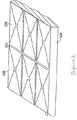
本発明の例示的な硬化性接着剤層の形成に使用される例示的な構造化剥離ライナーが図2に示される。硬化性接着剤層は、図2に示されるエンボス加工された剥離ライナー226の上にコーティングおよび/または積層することができ、このライナーは、剥離ライナーの面223の下に延在する角錐形凹部を含む。剥離ライナー226を取り外すと、その結果得られる硬化性接着剤層318は、図3に示されており、剥離ライナー226中の角錐型凹部228に対応する角錐型凸部328を含む。角錐型凸部328は、硬化性接着剤層318の面323から上方に延在しており、硬化性接着剤層318中に実質的に連続なチャネルの配列を形成している。
An exemplary structured release liner used to form an exemplary curable adhesive layer of the present invention is shown in FIG. The curable adhesive layer can be coated and / or laminated on the embossed
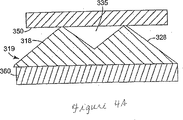
硬化性接着剤層318は、より詳細に後述し図4Aおよび4Bに示されるように、1つ以上の基材に接着することができる。図4Aおよび4Bを参照すると、第1の積層体は、基材360と、構造化表面を319を有する硬化性接着剤層318とを有する。剥離ライナー126(図4Aおよび4Bには示されていない)を取り外した後、硬化性接着剤層318の露出面319を第2の基材350と接触させて第2の積層体を形成することができる。基材350および360は、剛性であっても可撓性であってもよい。基材350および360のそれぞれは独立して、希望に応じてパターンおよび溝を有するように表面改質することができる。基材350および360の表面トポグラフィーは、硬化性接着剤層318中の構造化パターンとは完全に無関係である。
The curable
2.硬化性接着剤層の物理的性質
本発明の硬化性接着剤層は、少なくとも以下の望ましい物理的性質を有する。
2. Physical Properties of Curable Adhesive Layer The curable adhesive layer of the present invention has at least the following desirable physical properties.
a.接着剤の粘着性
本発明の硬化性接着剤層は、基材に接着するための十分な粘着性を有するように配合される。所与の基材に対する適切な接着剤の選択は、一般に当業者には公知であり、それによって希望する適切な程度の粘着性が得られる。望ましい粘着性の程度は、用途に応じて変動しうる。場合によっては、非常に粘着性の高い接着剤が望ましいこともあるし、別の場合では低粘着性接着剤が望ましい。粘着性は、接着剤が硬化して構造的接着が形成されるまで、基材に接着させるため、または2つの基材を互いに接着させるために十分であることが望ましい。
a. Adhesive adhesiveness The curable adhesive layer of the present invention is blended so as to have sufficient adhesiveness to adhere to a substrate. The selection of an appropriate adhesive for a given substrate is generally known to those skilled in the art, thereby obtaining the appropriate degree of tack desired. The desired degree of tack may vary depending on the application. In some cases, a highly tacky adhesive may be desirable, while in other cases a low tack adhesive is desirable. The tack is desirably sufficient to adhere to the substrate or to adhere the two substrates together until the adhesive is cured to form a structural bond.
所与の基材上に硬化性接着剤層を配置することが特に重要である場合、接着剤構造の基材に対する初期の接触を制限するために、トポグラフィー的特徴上に他の構造または材料を含むと有用なことがある。硬化性接着剤のトポグラフィー的特徴が、接着剤の特徴と基材との間の初期接触を制限するような特徴である場合には、追加の構造は不要となることもある。たとえば、特徴が角錐型である場合、角錐の先端部によって接触が制限され、そのため、接着剤層に強い接着が形成されず、必要に応じて取り外しや再配置が可能となる。接着剤が適切に配置されると、硬化性接着剤層を2つの基材の間に積層するために圧力が加えられ、角錐の先端部は基材を互いに保持するために十分平坦になることができ、一方角錐の残りの部分の形状は、たとえば実質的に角錐台を形成する。特徴の接着面が平坦である場合、たとえば、角錐台または平坦な六角形である場合、他の追加材料を加えることで、接着剤を配置または再配置できるように初期接着強度を制御しやすいようにすることができる。初期接着を制御するために使用することができる他の追加材料は、非接着性ビーズ、たとえばガラスまたはポリマーのビーズ、非接着性バブル、接着剤表面上に印刷された非接着材料の点、わずかに粘着性または非粘着性のペグである。追加材料は、(i)接着剤層のトポグラフィー的特徴を形成する硬化性接着剤層の外面上、(ii)接着剤層のトポグラフィー的特徴を形成する位置以外の硬化性接着剤層の外面上、または(iii)それらの組み合わせに存在することができる。接着剤が配置され積層された後で、硬化させて構造的接着を形成させることができる。 If it is particularly important to place a curable adhesive layer on a given substrate, other structures or materials on topographic features may be used to limit the initial contact of the adhesive structure to the substrate. May be useful. If the topographical characteristics of the curable adhesive are such that it limits the initial contact between the adhesive characteristics and the substrate, additional structure may not be necessary. For example, when the feature is a pyramid shape, the contact is limited by the tip of the pyramid, so that strong adhesion is not formed on the adhesive layer, and it can be removed and rearranged as necessary. When the adhesive is properly placed, pressure is applied to laminate the curable adhesive layer between the two substrates, and the pyramid tips are flat enough to hold the substrates together. While the shape of the rest of the pyramid, for example, substantially forms a truncated pyramid. If the adhesive surface of the feature is flat, for example, a truncated pyramid or a flat hexagon, adding other additional materials can help control the initial bond strength so that the adhesive can be placed or repositioned Can be. Other additional materials that can be used to control initial adhesion are non-adhesive beads, such as glass or polymer beads, non-adhesive bubbles, non-adhesive material dots printed on the adhesive surface, a few It is a sticky or non-sticky peg. The additional material can be (i) on the outer surface of the curable adhesive layer that forms the topographic features of the adhesive layer, and (ii) in the curable adhesive layer other than at the location that forms the topographic features of the adhesive layer. It can be present on the exterior surface or (iii) in combinations thereof. After the adhesive is placed and laminated, it can be cured to form a structural bond.
b.高温で形状を維持し流動に対して抵抗する構造状態に硬化する能力
本発明の硬化性接着剤層は硬化して、約37.8℃(100°F)を超える温度に曝露した場合に初期構造化表面プロファイルを実質的に維持する構造状態となる。本発明の硬化性接着剤層は少なくとも部分的に硬化して部分的に硬化した硬化性接着剤層を形成することができ、これはさらに、約37.8℃(100°F)を超える温度に曝露した場合に、巨視的な流動に対して抵抗し構造化形状(すなわち、トポグラフィー的特徴)を実質的に維持する。37.8℃(100°F)を超える温度に上昇すると、硬化性接着剤層の接着剤組成物のさらなる重合および/または架橋が起こる場合があるが、従来の感圧接着剤に見られるようなトポグラフィー的特徴の消失は起こらない。部分的に硬化した接着剤は、基材表面上でぬれることによって微視的な流動が起こり、基材への接着および/または積層による変形が起こることができる。硬化性接着剤層の完全に硬化したトポグラフィー的特徴は、構造化形状を全く側なうことなく、最高で少なくとも約32℃(90°F)の温度に曝露することができる。さらに、硬化した接着剤は、加圧下で永続的変形が起こることがない。
b. Ability to cure to a structural state that maintains shape and resists flow at elevated temperatures The curable adhesive layer of the present invention is initially cured when exposed to temperatures in excess of about 37.8 ° C. (100 ° F.). A structural state is obtained that substantially maintains the structured surface profile. The curable adhesive layer of the present invention can be at least partially cured to form a partially cured curable adhesive layer, which is further at a temperature above about 37.8 ° C. (100 ° F.). Resists macroscopic flow and substantially maintains the structured shape (ie, topographic features) when exposed to. Increasing the temperature above 37.8 ° C. (100 ° F.) may cause further polymerization and / or cross-linking of the adhesive composition of the curable adhesive layer, as seen in conventional pressure sensitive adhesives The loss of topographical features does not occur. Partially cured adhesives can be microscopically flowed by wetting on the substrate surface and can be deformed by adhesion to the substrate and / or lamination. The fully cured topographic features of the curable adhesive layer can be exposed to temperatures of up to at least about 32 ° C. (90 ° F.) without any side to the structured shape. Further, the cured adhesive does not undergo permanent deformation under pressure.
約37.8℃(100°F)を超える温度に曝露した場合に本発明の硬化性接着剤層がクリープに抵抗し構造化形状を維持する能力は、少なくとも部分的に硬化した接着剤層内部の重合性および/または架橋性の成分に主として起因するものと理解すべきである。ある種の充填剤によって、充填剤と接着材料との間に化学的または物理的相互作用が存在する場合には特に、部分的に硬化した接着剤層に剛性または弾性率を付与することができる。しかし、本発明の少なくとも部分的に硬化した接着剤層は、硬化性接着剤層が充填剤およびその他の固体添加剤を含有しない場合でさえも、約37.8℃(100°F)を超える温度に曝露した場合に流動に抵抗し構造化形状を維持する。 The ability of the curable adhesive layer of the present invention to resist creep and maintain a structured shape when exposed to temperatures in excess of about 37.8 ° C. (100 ° F.) is at least partially internal to the cured adhesive layer. It should be understood that this is mainly due to the polymerizable and / or crosslinkable components. Certain fillers can impart stiffness or modulus to the partially cured adhesive layer, especially when there is a chemical or physical interaction between the filler and the adhesive material. . However, the at least partially cured adhesive layers of the present invention exceed about 37.8 ° C. (100 ° F.) even when the curable adhesive layer does not contain fillers and other solid additives. Resists flow and maintains a structured shape when exposed to temperature.
3.硬化性接着剤層の成分
本発明の硬化性接着剤層は、前述の物理的性質を有する硬化性接着剤層が得られるあらゆる組み合わせの成分を含むことができる。前述の性質が得られる多数の例示的成分について以下に説明する。
3. Components of Curable Adhesive Layer The curable adhesive layer of the present invention can contain any combination of components that provides a curable adhesive layer having the aforementioned physical properties. A number of exemplary components that provide the aforementioned properties are described below.
a.エポキシ
本発明の例示的な一実施態様においては、硬化性接着剤層は、1種類以上のエポキシを含む。好適なエポキシ材料としては、限定するものではないが、カチオン重合性モノマーが挙げられ、多種多様のものが化学および接着剤の技術分野でよく知られている。たとえば、米国特許第5,897,727号明細書を参照することができ、この開示全体を本明細書に援用する。有用なエポキシ成分の一般的な例としては、エポキシモノマーおよびマクロマー、多官能性エポキシ架橋剤、ならびに脂肪族および環状のエポキシモノマーおよびマクロマーが挙げられる。直接的に、あるいは架橋剤またはその他の架橋性化学物質を介して、硬化性接着剤組成物内の他の成分、たとえばアクリレート成分と反応して相互に反応した相互侵入ポリマー網目(IPN)を形成することができる官能性を、エポキシ成分は含むことができる。接着強度、完全性、および安定性を含めた所望の性質のバランスが得られるように、接着剤の他の成分と組み合わせて好ましいエポキシを選択することができる。
a. Epoxy In one exemplary embodiment of the invention, the curable adhesive layer comprises one or more epoxies. Suitable epoxy materials include, but are not limited to, cationically polymerizable monomers, and a wide variety are well known in the chemical and adhesive arts. For example, reference may be made to US Pat. No. 5,897,727, the entire disclosure of which is hereby incorporated by reference. Common examples of useful epoxy components include epoxy monomers and macromers, multifunctional epoxy crosslinkers, and aliphatic and cyclic epoxy monomers and macromers. Directly or through crosslinkers or other crosslinkable chemicals, react with other components in the curable adhesive composition, such as acrylate components, to form an interpenetrating polymer network (IPN) that reacts with each other. Functionalities that can be made can include an epoxy component. Preferred epoxies can be selected in combination with other components of the adhesive to achieve a desired balance of properties including bond strength, integrity, and stability.
本発明で使用すると好適なエポキシとしては、限定するものではないが、米国特許第3,117,099号明細書、同第3,018,262号明細書、同第5,252,694号明細書、および同第5,897,727号明細書に開示されるエポキシが挙げられ、これらすべての開示全体を本明細書に援用する。 Epoxies suitable for use in the present invention include, but are not limited to, U.S. Pat. Nos. 3,117,099, 3,018,262, and 5,252,694. And the epoxies disclosed in US Pat. No. 5,897,727, all of which are incorporated herein in their entirety.
多種多様の市販のエポキシドが入手可能であり、リー(Lee)およびネビル(Neville)による「エポキシ樹脂ハンドブック」(Handbook of Epoxy Resins)、マグローヒル・ブック・カンパニー(McGraw Hill Book Company)、ニューヨーク(New York)(1967)、およびP.F.ブリンズ(Bruins)による「エポキシ樹脂技術」(Epoxy Resin Technology)、ジョン・ワイリー・アンド・サンズ(John Wiley & Sons)、ニューヨーク(New York)(1968)、およびC.A.メイ(May)編著による「エポキシ樹脂:化学および技術、第2版」(Epoxy Resins:Chemistry and Technology,2nd Edition)、マーセル・デッカー・インコーポレイテッド(Marcel Dekker,Inc.)ニューヨーク(New York)(1988)に挙げられている。本発明での使用に好適な市販のエポキシドとしては、テキサス州ヒューストンのリゾリューション・パフォーマンス・プロダクションズ(Resolution Performance Productions,Houston,Texas)より入手可能な商品名「エポン」(EPON)で入手可能なエポキシ;ミシガン州ミッドランドのダウ・ケミカル・カンパニー(Dow Chemical Company,Midland,Michigan)より入手可能な「DER」;ニューヨーク州ブルースターのバンチコ(Vantico,Brewster,New York)より入手可能な「アラルダイト」(ARALDITE);ニューヨーク州ブルースターのバンチコ(Vantico,Brewster,New York)より入手可能な「タクティクス」(TACTIX);ペンシルバニア州フィラデルフィアのFMCコーポレーション(FMC Corp.,Philadelphia,Pennsylvania)より入手可能な「オキシロン2001」(OXIRON 2001);またはペンシルバニア州フィラデルフィアのエルフ・アトケム(Elf Atochem,Philadelphia,Pennsylvania)の「ポリbd」(Poly bd);ならびに「AF」名称:「AF 42」、「AF 111」、「AF 126−2」、「AF 163−2」、「AF 3109−2」、「AF 191」、「AF 2635」、「AF 3002」、「AF 3024」、および「AF 3030FST」を有するものなどの「3Mスコッチ−ウェルド構造的接着フィルム」(3M Scotch−Weld Structural Adhesive Film)が挙げられるが、これらに限定されるものではない。 A wide variety of commercially available epoxides are available, “Handbook of Epoxy Resins” by Lee and Neville, Handbook of Epoxy Resins, McGraw Hill Book Company, New York ) (1967), and p. F. “Epoxy Resin Technology” by Bruns, John Wiley & Sons, New York (1968), and C.I. A. Mei (May) written and edited by "epoxy resin: Chemistry and Technology, Second Edition" (Epoxy Resins: Chemistry and Technology, 2 nd Edition), Marcel Dekker, Inc. (. Marcel Dekker, Inc) New York (New York) ( 1988). A commercially available epoxide suitable for use in the present invention is available under the trade name "EPON" (EPON) available from Resolution Performance Productions, Houston, Texas, Houston, Texas. Epoxy; “DER” available from Dow Chemical Company, Midland, Michigan; “Araldite” available from Vantico, Brewster, New York, Bluestar, NY ARALDITE); Vantico, Brewster, New York, Blue Star, NY Available "Tactix"(TACTIX);"Oxylon2001" (OXIRON 2001) available from FMC Corporation of Philadelphia, PA (Oxylon 2001); or Elf Atchem, Philadelphia, Pennsylvania (E "Poly bd" of Atochem, Philadelphia, Pennsylvania); and "AF" names: "AF 42", "AF 111", "AF 126-2", "AF 163-2", "AF 3109- “3M Scotch-Weld structures such as those having“ 2 ”,“ AF 191 ”,“ AF 2635 ”,“ AF 3002 ”,“ AF 3024 ”, and“ AF 3030 FST ” Adhesive film ”(3M Scotch-Weld Structural Adhesive Film), but is not limited thereto.
結果として得られる硬化性接着剤層の接着剤組成物が前述の性質を有する限り、硬化性接着剤層は、任意の量で1種類以上のエポキシ樹脂を含むことができる。本発明の望ましい一実施態様においては、硬化性接着剤層は、硬化性接着剤層の接着剤組成物の全質量を基準にして約90質量%までの量の1種類以上のエポキシ樹脂を含む。本発明のさらに望ましい実施態様においては、硬化性接着剤層は、硬化性接着剤層の接着剤組成物の全質量を基準にして約20質量%〜約80質量%の量の1種類以上のエポキシ樹脂を含む。 As long as the resulting adhesive composition of the curable adhesive layer has the properties described above, the curable adhesive layer can include one or more epoxy resins in any amount. In one desirable embodiment of the present invention, the curable adhesive layer comprises one or more epoxy resins in an amount up to about 90% by weight, based on the total weight of the adhesive composition of the curable adhesive layer. . In a further preferred embodiment of the invention, the curable adhesive layer is one or more types in an amount of about 20% to about 80% by weight, based on the total weight of the adhesive composition of the curable adhesive layer. Contains epoxy resin.
b.ポリアクリレート
本発明の硬化性接着剤層は、1種類以上のポリアクリレート成分をさらに含むことができる。本明細書で使用される場合、用語「ポリアクリレート成分」とは、一般に(メタ)アクリレートモノマーの重合によって調製されるポリマー成分を意味する。本明細書ではアクリレートモノマーおよびメタクリレートモノマーを一括して「(メタ)アクリレート」モノマーと呼ぶ。このような1種類以上の(メタ)アクリレートモノマーと、場合によってはあらゆる種々の他の有用な1種類以上のモノマーとから調製されたポリマーを一括して「ポリアクリレート」と呼ぶ。これらのポリマーは、ホモポリマーであってもよいし、場合によっては他の非(メタ)アクリレート、たとえばビニル−不飽和のモノマーと組み合わせられるコポリマーであってもよい。このようなポリアクリレートポリマーおよびそれらのモノマーは、ポリマーおよび接着剤の技術分野においてはよく知られている。
b. Polyacrylate The curable adhesive layer of the present invention can further comprise one or more polyacrylate components. As used herein, the term “polyacrylate component” means a polymer component that is generally prepared by polymerization of (meth) acrylate monomers. In this specification, acrylate monomers and methacrylate monomers are collectively referred to as “(meth) acrylate” monomers. Polymers prepared from one or more such (meth) acrylate monomers and optionally any other useful one or more monomers are collectively referred to as “polyacrylates”. These polymers may be homopolymers or, optionally, copolymers that are combined with other non- (meth) acrylates such as vinyl-unsaturated monomers. Such polyacrylate polymers and their monomers are well known in the polymer and adhesive arts.
種々の異なる(メタ)アクリレートモノマーおよびポリアクリレートを本発明で使用することができる。望ましくは、ポリアクリレートは、前述したようなエポキシ成分と直接または間接に結合してIPNを形成する1つ以上の反応性官能基を含有する。これらの反応性官能基は、ヒドロキシ(−OH)または酸性(たとえばカルボン酸−COOH)反応性基などのあらゆる公知の反応性基であってよい。これらの基は、たとえば、ポリアクリレートの調製においてアクリル酸モノマーなどの適切なモノマーを加えることによって、ポリアクリレートに導入することができる。あるいは、ポリアクリレートとエポキシとの間のこのような相互反応は、エポキシアクリレートなどの二官能性または多官能性モノマーとともにポリアクリレートと反応することができるグラフト化基を使用することによって実現することができる。相互反応したIPNを形成するためのさらに別の例は、エポキシ官能基をポリアクリレート主鎖上に導入することである。すべてのエポキシ官能系は、カチオン開始剤を使用して硬化させることができ、フリーラジカル開始剤などの他の開始剤は不要である。 A variety of different (meth) acrylate monomers and polyacrylates can be used in the present invention. Desirably, the polyacrylate contains one or more reactive functional groups that directly or indirectly bind to an epoxy component as described above to form an IPN. These reactive functional groups may be any known reactive group such as a hydroxy (—OH) or acidic (eg, carboxylic acid —COOH) reactive group. These groups can be introduced into the polyacrylate, for example, by adding a suitable monomer such as an acrylic acid monomer in the preparation of the polyacrylate. Alternatively, such interaction between the polyacrylate and the epoxy can be achieved by using a grafting group that can react with the polyacrylate with a difunctional or polyfunctional monomer such as an epoxy acrylate. it can. Yet another example for forming an interacted IPN is to introduce an epoxy functional group onto the polyacrylate backbone. All epoxy functional systems can be cured using a cationic initiator and no other initiators such as free radical initiators are required.
本発明で使用すると好適なポリアクリレートポリマーの具体例としては、限定するものではないが、米国特許第5,252,694号明細書、および同第5,086,088号明細書に記載されるようなフリーラジカル重合性アクリレートモノマーまたはオリゴマーから調製されるポリマー;ならびに米国特許出願第10/005,669号明細書(発明の名称「複合接着剤、物品、および方法」(HYBRID ADHESIVES,ARTICLES,AND METHODS)、2001年11月2日出願)、および米国特許出願第10/331,374号明細書(発明の名称「硬化性感圧接着剤組成物(CURABLE PRESSURE−SENSITIVE ADHESIVE COMPOSITIONS)」、2002年出願)に開示されるポリアクリレートが挙げられ、これらすべての開示全体を本明細書に援用する。 Specific examples of polyacrylate polymers suitable for use in the present invention include, but are not limited to, US Pat. Nos. 5,252,694 and 5,086,088. Polymers prepared from such free-radically polymerizable acrylate monomers or oligomers; and US patent application Ser. No. 10 / 005,669 (HITBRID ADHEESIVES, ARTICLES, AND (METHODS), filed Nov. 2, 2001), and US patent application Ser. No. 10 / 331,374 (invention title: “CURABLE PRESURE-SENSITIVE ADHESIVE COMPOSITIONS”), 2002 application. ) The disclosed polyacrylates are listed, the entire disclosures of all of which are hereby incorporated by reference.
本発明で使用すると好適な市販の(メタ)アクリレート樹脂の例としては、どちらもケンタッキー州ルイビルのゼオン・ケミカルズ・カンパニー・インコーポレイテッド(Zeon Chemicals Company、Inc.,Louisville、KY)より入手可能な商品名ハイテンプ(HYTEMP)TMおよびニポール(NIPOL)TMで販売される硬化性アクリレート樹脂が挙げられるが、これらに限定されるものではない。ハイテンプ(HYTEMP)TMおよびニポール(NIPOL)TMシリーズのポリアクリレートとしては、ハイテンプ(HYTEMP)TM4051、および4051EP、ならびにニポール(NIPOL)TMAR−31(ケンタッキー州ルイビルのゼオン・ケミカルズ・カンパニー・インコーポレイテッド(Zeon Chemicals Company、Inc.,Louisville、KY))などのポリアクリレートが挙げられる。本発明で使用すると好適な他の市販のアクリレート樹脂としては、ベイマック(VAMAC)TMシリーズのエチレン/アクリルエラストマー、たとえばベイマック(VAMAC)TMGおよびベイマック(VAMAC)TMD(デラウェア州ウィルミントンのデュポン・パッケージング・アンド・インダストリアル・ポリマー(DuPont Packaging and Industrial Polymers,Wilmington,DE);ロタデル(LOTADER)TMおよびロタリル(LOTARYL)TM(ペンシルバニア州フィラデルフィアのアトフィナ・ケミカルズ・インコーポレイテッド(Atofina Chemicals Inc.,Philadelphia,PA))シリーズのアクリルエラストマーおよびエチレン−アクリル酸エステルコポリマー、たとえばロタデル(LOTADER)TM4700、ならびにロタリル(LOTARYL)TM35BA320、35MA03、および35MA05(ペンシルバニア州フィラデルフィアのアトフィナ・ケミカルズ・インコーポレイテッド(Atofina Chemicals Inc.,Philadelphia,PA));ユーロプレン(EUROPRENE)TMシリーズのアクリルゴム、たとえばユーロプレン(EUROPRENE)TMAR53 EP、AR 156 LTR、ユーロプレン(EUROPRENE)TMC、LおよびR(テキサス州ヒューストンのエニケム・アメリカ・インコーポレイテッド(EniChem America Inc.,Houston,TX)が挙げられるが、これらに限定されるものではない。 Examples of commercially available (meth) acrylate resins suitable for use in the present invention are both commercially available from Zeon Chemicals Company, Inc., Louisville, KY, Louisville, Kentucky. Examples include, but are not limited to, curable acrylate resins sold under the names HYTEMP ™ and NIPOL ™ . HYTEMP TM and NIPOL TM series of polyacrylates include HYTEMP TM 4051 and 4051EP, and NIPOL TM AR-31 (Zeon Chemicals Company, Inc., Louisville, Kentucky). (Zeon Chemicals Company, Inc., Louisville, KY)). Other commercially available acrylate resins suitable for use in the present invention include VAMAC TM series of ethylene / acrylic elastomers such as VAMAC TM G and VAMAC TM D (DuPont, Wilmington, Del.). Packaging and Industrial Polymers (DuPont Packaging and Industrial Polymers, Wilmington, DE); Rotader ™ and LOTARYL ™ (Atophia Chemicals, Inc., Philadelphia, PA) , PA)) series acrylic elastomer Fine ethylene - acrylic acid ester copolymers, for example Rotaderu (LOTADER) TM 4700, and Rotariru (LOTARYL) TM 35BA320,35MA03, and 35MA05 (Philadelphia, PA ATOFINA Chemicals, Inc., (Atofina Chemicals Inc., Philadelphia, PA ) ); Europrene ™ series of acrylic rubbers, such as Europrene ™ AR53 EP, AR 156 LTR, Europrene ™ C, L and R (Enechem America Inc., Houston, Texas) ., Houston, TX Including without being limited thereto.
結果として得られる硬化性接着剤層の接着剤組成物が前述の性質を有する限り、硬化性接着剤層は、任意の量で1種類以上の(メタ)アクリレート樹脂を含むことができる。本発明の望ましい一実施態様においては、硬化性接着剤層は、硬化性接着剤層の接着剤組成物の全質量を基準にして約90質量%までの量の1種類以上の(メタ)アクリレート樹脂を含む。本発明のさらに別の実施態様においては、硬化性接着剤層は、硬化性接着剤層の接着剤組成物の全質量を基準にして約20質量%〜約80質量%の量の1種類以上の(メタ)アクリレート樹脂を含む。 As long as the resulting adhesive composition of the curable adhesive layer has the properties described above, the curable adhesive layer can contain one or more (meth) acrylate resins in any amount. In a preferred embodiment of the present invention, the curable adhesive layer is one or more (meth) acrylates in an amount up to about 90% by weight, based on the total weight of the adhesive composition of the curable adhesive layer. Contains resin. In yet another embodiment of the invention, the curable adhesive layer is one or more of an amount of about 20% to about 80% by weight, based on the total weight of the adhesive composition of the curable adhesive layer. (Meth) acrylate resin.
c.エチレン酢酸ビニルコポリマー
本発明の別の例示的な実施態様においては、硬化性接着剤層は、1種類以上の熱可塑性エチレン−酢酸ビニルコポリマー樹脂を含む。本発明の望ましい一実施態様においては、硬化性接着剤層は、1種類以上の熱可塑性エチレン−酢酸ビニルコポリマー樹脂とともに前述の1種類以上のエポキシを含む。好適な熱可塑性エチレン−酢酸ビニルコポリマー樹脂としては、限定するものではないが、米国特許出願第09/823,189号明細書(発明の名称「構造的接着テープおよびそれを含む物品」(STRUCTURAL BONDING TAPES AND ARTICLES CONTAINING THE SAME)、2001年3月29日出願)に開示される熱可塑性エチレン−酢酸ビニルコポリマー樹脂が挙げられ、この開示全体を本明細書に援用する。
c. Ethylene Vinyl Acetate Copolymer In another exemplary embodiment of the present invention, the curable adhesive layer comprises one or more thermoplastic ethylene-vinyl acetate copolymer resins. In one desirable embodiment of the present invention, the curable adhesive layer comprises one or more of the aforementioned epoxies together with one or more thermoplastic ethylene-vinyl acetate copolymer resins. Suitable thermoplastic ethylene-vinyl acetate copolymer resins include, but are not limited to, US patent application Ser. No. 09 / 823,189 (“Structural Adhesive Tape and Articles Containing It” (STRUCTURE BONDING). TAPES AND ARTICLES CONTAINING THE SAME), filed Mar. 29, 2001), the disclosure of which is incorporated herein by reference in its entirety.
本発明で使用することができる市販のエチレン−酢酸ビニルコポリマーの例としては、エルバックス(ELVAX)TM210、250、260、および265(デラウェア州ウィルミントンのE.I.デュポン・ドゥ・ヌムール・アンド・カンパニー(E.I.Du Pont de Nemours and Co.,Wilmington,Del.))、およびATプラスチックス(AT Plastics)2820M EVAコポリマー(カナダのオンタリオ州ブランプトンのATプラスチックス・インコーポレイテッド(AT Plastics,Inc.,Brampton,Ontario,Canada))(28質量%酢酸ビニル);エルバックス(ELVAX)TM150(デラウェア州ウィルミントンのE.I.デュポン・ドゥ・ヌムール・アンド・カンパニー(E.I.Du Pont de Nemours and Co.,Wilmington,Del.))およびATプラスチックス(AT Plastics)3325M EVAコポリマー(カナダのオンタリオ州ブランプトンのATプラスチックス・インコーポレイテッド(AT Plastics,Inc.,Brampton,Ontario,Canada))(33質量%酢酸ビニル);エルバックス(ELVAX)TM40W(デラウェア州ウィルミントンのE.I.デュポン・ドゥ・ヌムール・アンド・カンパニー(E.I.Du Pont de Nemours and Co.,Wilmington,Del.))、レバプレン(LEVAPREN)TM400(ペンシルバニア州ピッツバーグのバイエル・コーポレーション(Bayer Corp.,Pittsburgh,Pa.))、およびATプラスチックス(AT Plastics)4030M(カナダのオンタリオ州ブランプトンのATプラスチックス・インコーポレイテッド(AT Plastics,Inc.,Brampton,Ontario,Canada))(40質量%酢酸ビニル);レバプレン(LEVAPREN)TM450、452、および456(ペンシルバニア州ピッツバーグのバイエル・コーポレーション(Bayer Corp.,Pittsburgh,Pa.))(45質量%酢酸ビニル);レバプレン(LEVAPREN)TM500HV(ペンシルバニア州ピッツバーグのバイエル・コーポレーション(Bayer Corp.,Pittsburgh,Pa.))(50質量%酢酸ビニル);レバプレン(LEVAPREN)TM600 HV(ペンシルバニア州ピッツバーグのバイエル・コーポレーション(Bayer Corp.,Pittsburgh,Pa.))(60質量%酢酸ビニル);レバプレン(LEVAPREN)TM700 HV(ペンシルバニア州ピッツバーグのバイエル・コーポレーション(Bayer Corp.,Pittsburgh,Pa.))(70質量%酢酸ビニル);ならびにレバプレン(LEVAPREN)TMKA 8479(ペンシルバニア州ピッツバーグのバイエル・コーポレーション(Bayer Corp.,Pittsburgh,Pa.))(80質量%酢酸ビニル)が挙げられるが、これらに限定されるものではない。 Examples of commercially available ethylene-vinyl acetate copolymers that can be used in the present invention include ELVAX ™ 210, 250, 260, and 265 (EI DuPont de Nemours, Wilmington, Del.). And EI Du Pont de Nemours and Co., Wilmington, Del.), And AT Plastics 2820M EVA copolymer (AT Plastics, Inc., Brampton, Ontario, Canada). , Inc., Brampton, Ontario, Canada )) (28 wt% vinyl acetate); ELVAX (ELVAX) TM 150 (Wilmington, E.I. DuPont De Nemours & Co. (EI Du Pont de Nemours and Co., Wilmington, Del.) And AT Plastics 3325M EVA copolymer (AT Plastics Incorporated, Brampton, Ontario, Canada) (AT Plastics, Inc., Brampton, Ontario, Canada)) (33 wt% vinyl acetate); ELVAX ™ 40W (EI DuPont de Nemours and Company, Wilmington, Del.) I. Du Pont de Nemours and Co., Wilmington, Del.)), LEVAPREN ™ 400 (Pitts, PA) Bayer Corp. (Bayer Corp., Pittsburgh, Pa.), And AT Plastics 4030M (AT Plastics, Inc., Brampton, Ontario, Canada) Canada)) (40 wt% vinyl acetate); LEVAPREN ™ 450, 452, and 456 (Bayer Corp., Pittsburgh, Pa.) (45 wt% vinyl acetate); (LEVAPREN) TM 500HV (Pittsburgh, Pa Bayer Corporation (Bayer Corp , Pittsburgh, Pa. )) (50 wt% vinyl acetate); LEVAPREN ™ 600 HV (Bayer Corp., Pittsburgh, Pa.) (60 wt% vinyl acetate); LEVAPREN ™ 700 HV (Bayer Corp., Pittsburgh, Pa.) (70 wt% vinyl acetate); and REVAPREN ™ KA 8479 (Bayer Corp., Pittsburgh, Bayer Corp., Pittsburgh, PA). , Pa.)) (80% by weight vinyl acetate), but is not limited thereto.
結果として得られる硬化性接着剤層の接着剤組成物が前述の性質を有する限り、本発明の硬化性接着剤層は、任意の量で1種類以上のエチレン−酢酸ビニルコポリマー樹脂を含むことができる。本発明の望ましい一実施態様においては、硬化性接着剤層は、硬化性接着剤層の接着剤組成物の全質量を基準にして約40質量%までの量の1種類以上のエチレン−酢酸ビニルコポリマー樹脂を含む。本発明のさらに別の実施態様においては、硬化性接着剤層は、硬化性接着剤層の接着剤組成物の全質量を基準にして約20質量%〜約35質量%の量の1種類以上のエチレン−酢酸ビニルコポリマー樹脂を含む。 As long as the resulting adhesive composition of the curable adhesive layer has the aforementioned properties, the curable adhesive layer of the present invention may contain one or more ethylene-vinyl acetate copolymer resins in any amount. it can. In one desirable embodiment of the invention, the curable adhesive layer is one or more ethylene-vinyl acetate in an amount up to about 40% by weight, based on the total weight of the adhesive composition of the curable adhesive layer. Contains a copolymer resin. In yet another embodiment of the invention, the curable adhesive layer is one or more of an amount of about 20% to about 35% by weight, based on the total weight of the adhesive composition of the curable adhesive layer. Of ethylene-vinyl acetate copolymer resin.
d.熱可塑性ポリエステル
本発明の別の例示的な実施態様においては、硬化性接着剤層は、1種類以上の熱可塑性ポリエステルを含む。本発明の望ましい一実施態様においては、硬化性接着剤層は、1種類以上の熱可塑性ポリエステルとともに、前述の1種類以上のエポキシを含む。好適なポリエステル成分としては、ガラス転移温度(Tg)が約10℃以下、望ましくは約5℃以下である非晶質の分枝ポリエステルが挙げられるが、これらに限定されるものではない。
d. Thermoplastic polyester In another exemplary embodiment of the present invention, the curable adhesive layer comprises one or more thermoplastic polyesters. In a preferred embodiment of the present invention, the curable adhesive layer comprises one or more of the aforementioned epoxies together with one or more thermoplastic polyesters. Suitable polyester components include, but are not limited to, amorphous branched polyesters having a glass transition temperature (T g ) of about 10 ° C. or less, desirably about 5 ° C. or less.
8グラムの試料について、走査速度20℃/分において−60℃〜200℃の示差走査熱分析(DSC)を行った場合に、非晶質の分枝ポリエステルは測定可能な結晶溶融挙動を示さないという点で、本発明に使用される非晶質の分枝ポリエステル成分を結晶質ポリエステルと区別することができる。DSC測定は、コネチカット州ノーウォークのパーキン・エルマー(Perkin Elmer,Norwalk,CT)のDSC7示差走査熱量計などの市販のDSC装置を使用すると好都合に実施される。 When subjected to differential scanning calorimetry (DSC) from −60 ° C. to 200 ° C. at a scanning rate of 20 ° C./min on an 8 gram sample, the amorphous branched polyester does not show measurable crystal melting behavior. In this respect, the amorphous branched polyester component used in the present invention can be distinguished from the crystalline polyester. DSC measurements are conveniently performed using a commercially available DSC instrument such as the DSC7 differential scanning calorimeter from Perkin Elmer, Norwalk, Conn.
溶融挙動は示さないが、非晶質の分枝ポリエステルは、DSC走査にかけると、ガラス転移温度を示す。非晶質の分枝ポリエステルのガラス転移温度は、望ましくは約10℃未満であり、より望ましくは約−20℃〜約5℃の範囲であり、さらにより望ましくは約−10℃〜約5℃の間である。 Although it does not exhibit melting behavior, amorphous branched polyesters exhibit a glass transition temperature when subjected to DSC scanning. The glass transition temperature of the amorphous branched polyester is desirably less than about 10 ° C, more desirably in the range of about -20 ° C to about 5 ° C, and even more desirably about -10 ° C to about 5 ° C. Between.
本発明で使用することができる市販のポリエステルの例としては、デグッサ(DeGussa)(ニュージャージー州パーシッパニー(Parsippany,N.J.))より市販される商品名ダイナポール(DYNAPOL)で販売されるポリエステルが挙げられるが、これに限定されるものではない。 Examples of commercially available polyesters that can be used in the present invention include polyesters sold under the trade name DYNAPOL sold by DeGussa (Parsippany, NJ). Although it is mentioned, it is not limited to this.
好適な熱可塑性ポリエステルとしては、限定するものではないが、米国特許出願第09/823,189号明細書(発明の名称「構造的接着テープおよびそれを含む物品」(STRUCTURAL BONDING TAPES AND ARTICLES CONTAINING THE SAME)、2001年3月29日出願)に開示される熱可塑性ポリエステルが挙げられ、この開示全体を本明細書に援用する。 Suitable thermoplastic polyesters include, but are not limited to, U.S. patent application Ser. No. 09 / 823,189 ("Structure Bonding Tapes and Articles Containing It"). SAME), filed Mar. 29, 2001), the disclosure of which is incorporated herein by reference in its entirety.
結果として得られる硬化性接着剤層の接着剤組成物が前述の性質を有する限り、硬化性接着剤層は、任意の量で1種類以上の熱可塑性ポリエステルを含むことができる。本発明の望ましい一実施態様においては、硬化性接着剤層は、硬化性接着剤層の接着剤組成物の全質量を基準にして約50質量%までの量の1種類以上の熱可塑性ポリエステルを含む。本発明のさらに別の実施態様においては、硬化性接着剤層は、硬化性接着剤層の接着剤組成物の全質量を基準にして約20質量%〜約50質量%の量の1種類以上の熱可塑性ポリエステルを含む。 As long as the resulting adhesive composition of the curable adhesive layer has the properties described above, the curable adhesive layer can include one or more thermoplastic polyesters in any amount. In a preferred embodiment of the present invention, the curable adhesive layer comprises one or more thermoplastic polyesters in an amount up to about 50% by weight, based on the total weight of the adhesive composition of the curable adhesive layer. Including. In yet another embodiment of the invention, the curable adhesive layer is one or more of an amount of about 20% to about 50% by weight, based on the total weight of the adhesive composition of the curable adhesive layer. Of thermoplastic polyester.
e.ウレタン材料
本発明の別の例示的な実施態様においては、硬化性接着剤層は、1種類以上のウレタン材料を含む。本明細書で使用される場合、用語「ウレタン材料」とは、本明細書では「イソシアネート」と呼ぶ少なくとも2つのイソシアネート基(−N=C=O)を含有する化合物と、少なくとも2つの活性水素含有基を含有する化合物との反応生成物から生成されるポリマーおよびプレポリマーを意味する。活性水素含有基の例としては、第1級アルコール、第2級アルコール、フェノール類、および水;第1級および第2級アミン(イソシアネートと反応して尿素結合を形成する);ならびにシラノール含有材料が挙げられる。多種多様なイソシアネート末端材料および適切な共反応物質はよく知られており、多くの種類が市販されている(たとえば、ギュンター・エルテル(Gunter Oertel)、「ポリウレタン・ハンドブック」(Polyurethane Handbook)、ハンター・パブリッシャー(Hanser Publishers)、ミュンヘン(Munich)(1985)を参照されたい)。
e. Urethane Material In another exemplary embodiment of the present invention, the curable adhesive layer comprises one or more urethane materials. As used herein, the term “urethane material” refers to a compound containing at least two isocyanate groups (—N═C═O), referred to herein as “isocyanate”, and at least two active hydrogens. It means a polymer and a prepolymer produced from a reaction product with a compound containing a containing group. Examples of active hydrogen-containing groups include primary alcohols, secondary alcohols, phenols, and water; primary and secondary amines that react with isocyanates to form urea linkages; and silanol-containing materials Is mentioned. A wide variety of isocyanate-terminated materials and suitable co-reactants are well known and many are commercially available (eg, Gunter Oertel, “Polyurethane Handbook”, Hunter Publisher (see Hanser Publishers, Munich, 1985).
本発明の望ましい一実施態様においては、硬化性接着剤層は、1種類以上のウレタン材料とともに、前述の1種類以上のエポキシおよび/または前述の1種類以上のポリアクリレートを含む。本発明で使用すると好適なウレタン材料としては、限定するものではないが、米国特許出願第10/157,260号明細書(発明の名称「セグメント化硬化性転写テープ」(SEGMENTED CURABLE TRANSFER TAPES)、2002年5月28日出願)に開示されるウレタン材料が挙げられ、この開示全体を本明細書に援用する。 In a preferred embodiment of the invention, the curable adhesive layer comprises one or more of the aforementioned epoxy and / or one or more of the polyacrylates together with one or more urethane materials. Urethane materials suitable for use in the present invention include, but are not limited to, US patent application Ser. No. 10 / 157,260 (SEGMENTED CURABLE TRANSFER TAPES), Urethane materials disclosed on May 28, 2002), the entire disclosure of which is incorporated herein by reference.
結果として得られる硬化性接着剤層の接着剤組成物が前述の性質を有する限り、硬化性接着剤層は、任意の量で1種類以上のウレタン材料を含むことができる。本発明の望ましい一実施態様においては、硬化性接着剤層は、硬化性接着剤層の接着剤組成物の全質量を基準にして約50質量%までの量の1種類以上のウレタン材料を含む。本発明のさらに別の実施態様においては、硬化性接着剤層は、硬化性接着剤層の接着剤組成物の全質量を基準にして約20質量%〜約50質量%の量の1種類以上のウレタン材料を含む。 As long as the resulting adhesive composition of the curable adhesive layer has the properties described above, the curable adhesive layer can include one or more urethane materials in any amount. In a preferred embodiment of the present invention, the curable adhesive layer comprises one or more urethane materials in an amount up to about 50% by weight, based on the total weight of the adhesive composition of the curable adhesive layer. . In yet another embodiment of the invention, the curable adhesive layer is one or more of an amount of about 20% to about 50% by weight, based on the total weight of the adhesive composition of the curable adhesive layer. Of urethane materials.
f.モノおよびマルチアクリレートオリゴマー
本発明の別の例示的な実施態様においては、硬化性接着剤層は、1種類以上のモノおよび/またはマルチアクリレートオリゴマーを含む。本明細書で使用される場合、用語「モノアクリレートオリゴマー」とは、ただ1つのアクリレート官能基を有するオリゴマーを意味し、一方、用語「マルチアクリレートオリゴマー」とは、少なくとも2つのアクリレート官能基を有するオリゴマーを意味する。本発明の望ましい一実施態様においては、硬化性接着剤層は、1種類以上のモノおよび/またはマルチアクリレートオリゴマーとともに、前述の1種類以上のポリアクリレートを含む。この望ましい実施態様においては、モノアクリレートは、前述のアクリレートコポリマーおよびマルチアクリレートオリゴマーと混合することによって、ポリマーの主鎖になることができる。アクリレート官能性は、末端基であってもよいし、オリゴマー鎖内部のある部位の上にグラフトすることもできる。組成物の他の成分と混合することによって、マルチアクリレートオリゴマーは、モノアクリレートオリゴマー主鎖と網目を形成するために必要な架橋および分枝を提供する。
f. Mono and multiacrylate oligomers In another exemplary embodiment of the invention, the curable adhesive layer comprises one or more mono and / or multiacrylate oligomers. As used herein, the term “monoacrylate oligomer” means an oligomer having only one acrylate functional group, while the term “multi-acrylate oligomer” has at least two acrylate functional groups. It means an oligomer. In a preferred embodiment of the present invention, the curable adhesive layer comprises one or more polyacrylates as described above together with one or more mono and / or multiacrylate oligomers. In this preferred embodiment, the monoacrylate can become the backbone of the polymer by mixing with the aforementioned acrylate copolymers and multiacrylate oligomers. The acrylate functionality can be a terminal group or can be grafted onto some site within the oligomer chain. By mixing with the other components of the composition, the multiacrylate oligomer provides the necessary crosslinking and branching to form a network with the monoacrylate oligomer backbone.
本発明で使用すると好適なモノおよびマルチアクリレートオリゴマーとしては、限定するものではないが、米国特許出願第10/331,374号明細書(発明の名称「硬化性感圧接着剤組成物」(CURABLE PRESSURE−SENSITIVE ADHESIVE COMPOSITIONS)、2002年12月30日出願)に開示されるモノおよびマルチアクリレートオリゴマーが挙げられ、この開示全体を本明細書に援用する。 Mono- and multi-acrylate oligomers suitable for use in the present invention include, but are not limited to, US patent application Ser. No. 10 / 331,374 (invention name “Curable Pressure Sensitive Adhesive Composition”). -SENSITIVE ADHESIVE COMPOSTIONS), filed December 30, 2002), the disclosure of which is incorporated herein in its entirety.
結果として得られる硬化性接着剤層の接着剤組成物が前述の性質を有する限り、硬化性接着剤層は、任意の量で1種類以上のモノおよびマルチアクリレートオリゴマーを含むことができる。本発明の望ましい一実施態様においては、硬化性接着剤層は、硬化性接着剤層の接着剤組成物の全質量を基準にして約60質量%までの量の1種類以上のモノおよびマルチアクリレートオリゴマーを含む。本発明のさらに別の実施態様においては、硬化性接着剤層は、硬化性接着剤層の接着剤組成物の全質量を基準にして約20質量%〜約60質量%の量の1種類以上のモノおよびマルチアクリレートオリゴマーを含む。 As long as the resulting adhesive composition of the curable adhesive layer has the properties described above, the curable adhesive layer can include one or more mono- and multi-acrylate oligomers in any amount. In one desirable embodiment of the invention, the curable adhesive layer is one or more mono and multiacrylates in an amount up to about 60% by weight, based on the total weight of the adhesive composition of the curable adhesive layer. Contains oligomers. In yet another embodiment of the invention, the curable adhesive layer is one or more of an amount of about 20% to about 60% by weight, based on the total weight of the adhesive composition of the curable adhesive layer. Of mono- and multi-acrylate oligomers.
g.シアン酸エステル材料
本発明のさらに別の例示的な実施態様においては、硬化性接着剤層は、1種類以上のシアン酸エステル材料を含む。本発明の望ましい一実施態様においては、硬化性接着剤層は、1種類以上のシアン酸エステル材料とともに、前述の1種類以上のエポキシおよび/または前述の1種類以上のポリアクリレートを含む。好適なシアン酸エステル材料(モノマーおよびオリゴマー)は、2つ以上の−O−C≡N官能基を有するものであり、たとえば、米国特許第5,143,785号明細書、同第3,962,184号明細書、同第4,022,755号明細書、同第4,026,913号明細書、同第3,595,900号明細書、同第4,740,584号明細書、同第4,709,008号明細書、同第4,528,366号明細書、同第3,733,349号明細書、同第4,195,132号明細書、および同第4,116,946号明細書に開示されるものが挙げられ、これらすべての開示全体を本明細書に援用する。
g. Cyanate material In yet another exemplary embodiment of the invention, the curable adhesive layer comprises one or more cyanate materials. In a preferred embodiment of the present invention, the curable adhesive layer comprises one or more of the aforementioned epoxies and / or one or more of the aforementioned polyacrylates together with one or more cyanate materials. Suitable cyanate materials (monomers and oligomers) are those having two or more —O—C≡N functional groups, for example, US Pat. Nos. 5,143,785, 3,962 , 184 specification, 4,022,755 specification, 4,026,913 specification, 3,595,900 specification, 4,740,584 specification, 4,709,008, 4,528,366, 3,733,349, 4,195,132, and 4,116 No. 946, the entire disclosure of which is incorporated herein by reference.
硬化性接着剤層中に存在する場合、1種類以上のシアン酸エステル材料は、硬化性接着剤層の接着剤組成物の全質量を基準にして約50質量%までの量で存在する。より望ましくは、存在する場合、1種類以上のシアン酸エステル材料は、硬化性接着剤層の接着剤組成物の全質量を基準にして約20質量%〜約50質量%の量で存在する。さらにより望ましくは、存在する場合、1種類以上のシアン酸エステル材料は、硬化性接着剤層の接着剤組成物の全質量を基準にして約30質量%〜約40質量%の量で存在する。 When present in the curable adhesive layer, the one or more cyanate material is present in an amount up to about 50% by weight, based on the total weight of the adhesive composition of the curable adhesive layer. More desirably, when present, the one or more cyanate ester materials are present in an amount of about 20% to about 50% by weight, based on the total weight of the adhesive composition of the curable adhesive layer. Even more desirably, when present, the one or more cyanate material is present in an amount of about 30% to about 40% by weight, based on the total weight of the adhesive composition of the curable adhesive layer. .
h.ビスマレイミド材料
硬化性接着剤層は、1種類以上のビスマレイミド材料をさらに含むことができる。好適なビスマレイミド材料の例は、N,N’−ビスマレイミドモノマーおよびプレポリマーとも呼ばれており、たとえば、1,2−エタンジアミン、1,6−ヘキサンジアミン、トリメチル−1,6−ヘキサンジアミン、1,4−ベンゼンジアミン、4,4’−メチレン−ビス(ベンゼンアミン)、2−メチル−l,4−ベンゼンジアミン、3,3’−メチレン−ビス(ベンゼンアミン)、3,3’−スルホニル−ビス(ベンゼンアミン)、4,4’−スルホニル−ビス(ベンゼンアミン)、3,3’−オキシ−ビス(ベンゼンアミン)、4,4’−オキシ−ビス(ベンゼンアミン)、4,4’−メチレン−ビス(シクロヘキサンアミン)、1,3−ベンゼンジメタンアミン、1,4−ベンゼンジメタンアミン、および4,4’−シクロヘキサン−ビス(ベンゼンアミン)のN,N’−ビスマレイミド、ならびにそれらの混合物が挙げられるが、これらに限定されるものではない。その他のN,N’−ビス−マレイミドおよびそれらの調製方法は、米国特許第3,562,223号明細書、同第3,627,780号明細書、同第3,839,358号明細書、および同第4,468,497号明細書に記載されており、これらすべての記載内容を本明細書に援用する。
h. Bismaleimide material The curable adhesive layer may further comprise one or more bismaleimide materials. Examples of suitable bismaleimide materials are also referred to as N, N′-bismaleimide monomers and prepolymers such as 1,2-ethanediamine, 1,6-hexanediamine, trimethyl-1,6-hexanediamine. 1,4-benzenediamine, 4,4′-methylene-bis (benzeneamine), 2-methyl-1,4-benzenediamine, 3,3′-methylene-bis (benzeneamine), 3,3′- Sulfonyl-bis (benzeneamine), 4,4′-sulfonyl-bis (benzeneamine), 3,3′-oxy-bis (benzeneamine), 4,4′-oxy-bis (benzeneamine), 4,4 '-Methylene-bis (cyclohexaneamine), 1,3-benzenedimethanamine, 1,4-benzenedimethanamine, and 4,4'-cyclohexane-bis ( N of Nzen'amin), N'-bismaleimide, and mixtures thereof, but is not limited thereto. Other N, N′-bis-maleimides and methods for their preparation are described in US Pat. Nos. 3,562,223, 3,627,780, and 3,839,358. And 4,468,497, the entire contents of which are incorporated herein by reference.
市販のビスマレイミド材料の代表例としては、4,4’−ビスマレイミドジフェニルメタン(「コンピミド・レジン(COMPIMIDE Resin)MDAB」)、および2,4’−ビスマレイミドトルエン(「コンピミド・レジン(COMPIMIDE Resin)TDAB」)などの商品名「コンピミド」(COMPIMIDE)でテキサス州ヒューストンのリゾリューション・パフォーマンス・プロダクションズ(Resolution Performance Productions,Houston,Texas)より入手可能な一連の材料、商品名「Qボンド」(Q−Bond)でカリフォルニア州サンディエゴのデクスター/クオンタム(Dexter/Quantum,San Diego,CA)より入手可能な一連の材料が挙げられる。 Representative examples of commercially available bismaleimide materials include 4,4'-bismaleimide diphenylmethane ("COMPIMIDE Resin MDAB") and 2,4'-bismaleimide toluene ("COMPIMIDE Resin"). A series of materials available from Resolution Performance Productions, Houston, Texas under the trade name “COMPIMIDE”, such as “TDAB”), the trade name “Q Bond” (Q -Bond) available from Dexter / Quantum, San Diego, CA, San Diego, California A series of materials.
硬化性接着剤層中に存在する場合、1種類以上のビスマレイミド材料は、硬化性接着剤層の接着剤組成物の全質量を基準にして約50質量%までの量で存在する。より望ましくは、存在する場合、1種類以上のビスマレイミド材料は、硬化性接着剤層の接着剤組成物の全質量を基準にして約20質量%〜約50質量%の量で存在する。さらにより望ましくは、存在する場合、1種類以上のビスマレイミド材料は、硬化性接着剤層の接着剤組成物の全質量を基準にして約30質量%〜約40質量%の量で存在する。 When present in the curable adhesive layer, the one or more bismaleimide materials are present in an amount up to about 50% by weight, based on the total weight of the adhesive composition of the curable adhesive layer. More desirably, when present, the one or more bismaleimide materials are present in an amount of about 20% to about 50% by weight, based on the total weight of the adhesive composition of the curable adhesive layer. Even more desirably, when present, the one or more bismaleimide materials are present in an amount of about 30% to about 40% by weight, based on the total weight of the adhesive composition of the curable adhesive layer.
i.硬化剤
硬化性接着剤層は、1種類以上の硬化剤または硬化作用物質をさらに含むことができる。用語「硬化剤」または「硬化作用物質」は広い範囲で使用され、従来硬化剤と見なされている材料だけではなく、硬化性材料の反応を触媒または加速する材料、ならびに硬化剤と触媒または促進剤との両方として作用することができる材料も含んでいる。2種類以上の硬化剤を組み合わせて使用することも可能である。硬化剤は、熱活性化硬化剤または光活性化硬化剤であってよい。
i. Curing Agent The curable adhesive layer can further include one or more curing agents or curing agents. The term “curing agent” or “curing agent” is used in a wide range, not only materials that are conventionally regarded as curing agents, but also materials that catalyze or accelerate the reaction of curable materials, as well as curing agents and catalysts or accelerators. Also included are materials that can act as both agents. Two or more kinds of curing agents can be used in combination. The curing agent may be a heat activated curing agent or a light activated curing agent.
本発明で使用すると好適な硬化剤としては、限定するものではないが、米国特許第4,503,211号明細書、同第4,751,138号明細書、同第4,868,288号明細書、および同第4,985,340号明細書、ならびに欧州特許出願第306,161号明細書、同第306,162号明細書、および同第0344911号明細書に開示される硬化剤が挙げられ、これらのすべての開示全体を本明細書に援用する。本発明の例示的な一実施態様においては、硬化性接着剤層は、アミン類から選択される1種類以上の硬化剤を含む。 Curing agents suitable for use in the present invention include, but are not limited to, U.S. Pat. Nos. 4,503,211, 4,751,138, and 4,868,288. And the curing agents disclosed in U.S. Pat. No. 4,985,340 and European Patent Applications Nos. 306,161, 306,162, and 0344911. And all of these disclosures are incorporated herein by reference. In one exemplary embodiment of the present invention, the curable adhesive layer includes one or more curing agents selected from amines.
好適な市販の開始剤としては、芳香族スルホニウム錯塩FX−512TM(ミネソタ州セントポールのミネソタ・マイニング・アンド・マニュファクチャリング・カンパニー(Minnesota Mining and Manufacturing Company,St.Paul,Minn.))、CD−1012TM、およびCD−1010TM(ペンシルバニア州エクストンのサートマー(Sartomer,Exton,Pa.));UVOXTM UVI−6974、芳香族スルホニウム錯塩(コネチカット州ダンベリーのユニオン・カーバイド・コーポレーション(Union Carbide Corp.,Danbury,CT));イルガキュア(IRGACURE)TM261、カチオン性有機金属錯塩(スイスのバーゼルのチバ・スペシャルティ・ケミカルズ(Ciba Specialty Chemicals,Basel,Switzerland));ならびにロドルシル(RHODORSIL)2074TMなどのロドルシル(RHODORSIL)TM製品(ニュージャージー州クランバリーのローディア・インコーポレイテッド(Rhodia Inc.,Cranbury,NJ))が挙げられるが、これらに限定されるものではない。 Suitable commercially available initiators include the aromatic sulfonium complex salt FX-512 ™ (Minnesota Mining and Manufacturing Company, St. Paul, Minn.), St. Paul, Minn. CD-1012 ™ , and CD-1010 ™ (Sartomer, Exton, Pa.); UVOX ™ UVI-6974, an aromatic sulfonium complex (Union Carbide Corp., Danbury, Connecticut). , Danbury, CT)); IRGACURE ™ 261, cationic organometallic complex (Swiss -Chisel Specialty Chemicals (Ciba Specialty Chemicals, Basel, Switzerland); and RODORSIL ™ products such as RHODOLSIL 2074 TM (Rhodia, Inc., Cranbury, NJ) NJ)), but is not limited thereto.
硬化性接着剤層は典型的には、硬化性接着剤層の接着剤組成物の全質量を基準にして約10質量%までの量の1種類以上の硬化剤を含む。 The curable adhesive layer typically comprises one or more curing agents in an amount up to about 10% by weight, based on the total weight of the adhesive composition of the curable adhesive layer.
j.添加剤
種々の添加剤またはその他の成分を、最終的な接着剤組成物の特定の特性を付与または改質することができる。添加剤は、硬化性接着剤層の所望の性質に悪影響を与えない量であれば、あらゆる量で存在することができる。硬化性接着剤層は典型的には、硬化性接着剤層の接着剤組成物の全質量を基準にして約50質量%までの量の1種類以上の添加剤を含む。例示的な添加剤としては、粘着付与剤、可塑剤、充填剤、酸化防止剤、安定剤、顔料、拡散材料、繊維、フィラメント、シリカ、処理シリカ、およびカーボンブラックが挙げられるが、これらに限定されるものではない。
j. Additives Various additives or other ingredients can impart or modify specific properties of the final adhesive composition. The additive can be present in any amount that does not adversely affect the desired properties of the curable adhesive layer. The curable adhesive layer typically includes one or more additives in an amount up to about 50% by weight, based on the total weight of the adhesive composition of the curable adhesive layer. Exemplary additives include, but are not limited to, tackifiers, plasticizers, fillers, antioxidants, stabilizers, pigments, diffusion materials, fibers, filaments, silica, treated silica, and carbon black. Is not to be done.
B.その他の層
前述の硬化性接着剤層以外に、本発明の硬化性接着物品は、硬化性接着剤層のいずれかの側の上に、1つ以上の追加層を含むことができる。1つ以上の追加層は、それぞれ独立して、一時的または永続的に硬化性接着物品の層に取り付けることができる。好適な追加層について以下に説明する。
B. Other Layers In addition to the curable adhesive layer described above, the curable adhesive article of the present invention can include one or more additional layers on either side of the curable adhesive layer. One or more additional layers can each be independently or temporarily attached to a layer of the curable adhesive article. Suitable additional layers are described below.
1.追加の接着剤層
本発明の硬化性接着物品は、硬化性接着剤層のいずれかの側の上に、1つ以上の追加の接着剤層を含むことができる。1つ以上の追加の接着剤層は、当技術分野で公知のあらゆる好適な接着剤であってよい。望ましくは、存在する場合には、追加の接着剤層は、圧力、熱またはそれらの組み合わせによって活性化可能な接着剤である。好適な追加の接着剤層組成物としては、(メタ)アクリレート、ゴム/樹脂、エポキシ、ウレタン、またはそれらの組み合わせを主成分とする接着剤組成物が挙げられるが、これらに限定されるものではない。追加の接着剤層は、溶液、水系、またはホットメルトのコーティング方法によって硬化性接着剤層の外面に適用することができる。追加の接着剤層としては、ホットメルトコーティングされた配合物、転写コーティングされた配合物、溶媒コーティングされた配合物、およびラテックスコーティングされた配合物、ならびに積層、熱活性化、および水活性化接着剤、ならびに結合剤を挙げることができる。より望ましくは、追加の接着剤層は感圧接着剤を含む。
1. Additional Adhesive Layers The curable adhesive article of the present invention can include one or more additional adhesive layers on either side of the curable adhesive layer. The one or more additional adhesive layers may be any suitable adhesive known in the art. Desirably, when present, the additional adhesive layer is an adhesive that can be activated by pressure, heat, or a combination thereof. Suitable additional adhesive layer compositions include, but are not limited to, adhesive compositions based on (meth) acrylates, rubber / resins, epoxies, urethanes, or combinations thereof. Absent. The additional adhesive layer can be applied to the outer surface of the curable adhesive layer by solution, aqueous, or hot melt coating methods. Additional adhesive layers include hot melt coated formulations, transfer coated formulations, solvent coated formulations, and latex coated formulations, as well as lamination, heat activated, and water activated adhesion. Mention may be made of agents, as well as binders. More desirably, the additional adhesive layer comprises a pressure sensitive adhesive.
好適な感圧接着剤の例としては、ポリ(メタ)アクリレート;ポリビニルエーテル;天然ゴム、ポリイソプレン、およびポリブタジエンなどのジエンゴム;ポリイソブチレン;ポリクロロプレン;ブチルゴム;ブタジエン−アクリロニトリルポリマー;熱可塑性エラストマー;スチレン−イソプレンおよびスチレン−イソプレン−スチレン(SIS)ブロックコポリマー、エチレン−プロピレン−ジエンポリマー、ならびにスチレン−ブタジエンポリマーなどのブロックコポリマー;ポリ−α−オレフィン;非晶質ポリオレフィン;シリコーン;エチレン酢酸ビニル、アクリル酸エチル、およびメタクリル酸エチルなどのエチレン含有コポリマー;ポリウレタン;ポリアミド;エポキシ;ポリビニルピロリドンおよびビニルピロリドンコポリマー;ポリエステル;ならびにこれらの混合物またはブレンド(連続相または不連続相)の一般的な組成物を主成分とする接着剤が挙げられるが、これらに限定されるものではない。前述したように追加の接着剤層の接着剤組成物は、粘着付与剤、可塑剤、充填剤、酸化防止剤、安定剤、顔料、拡散材料、繊維、およびフィラメントなどの添加剤を含有することができるが、これらに限定されるものではない。 Examples of suitable pressure sensitive adhesives include: poly (meth) acrylates; polyvinyl ether; diene rubbers such as natural rubber, polyisoprene, and polybutadiene; polyisobutylene; polychloroprene; butyl rubber; butadiene-acrylonitrile polymer; -Block copolymers such as isoprene and styrene-isoprene-styrene (SIS) block copolymers, ethylene-propylene-diene polymers, and styrene-butadiene polymers; poly-α-olefins; amorphous polyolefins; silicones; ethylene vinyl acetate, acrylic acid Ethylene-containing copolymers such as ethyl and ethyl methacrylate; polyurethane; polyamide; epoxy; polyvinylpyrrolidone and vinylpyrrolidone copoly Chromatography, polyesters, as well as adhesives based on general compositions of these mixtures or blends (continuous or discontinuous phase) and the like, but is not limited thereto. As described above, the adhesive composition of the additional adhesive layer contains additives such as tackifiers, plasticizers, fillers, antioxidants, stabilizers, pigments, diffusion materials, fibers, and filaments. However, it is not limited to these.
本発明の一実施態様においては、硬化性接着物品は、1つの硬化性接着剤層とともに、少なくとも1つの追加の接着剤層を含み、少なくとも1つの追加の接着剤層は、連続または不連続コーティングの形態で硬化性接着剤層の外面上に存在する。追加の接着剤層が不連続コーティングとして存在する場合、追加の接着剤層は、硬化性接着剤層の外面に沿って点、正方形、三角形、線、またはその他のあらゆる形状で存在することができる。 In one embodiment of the invention, the curable adhesive article includes at least one additional adhesive layer together with one curable adhesive layer, the at least one additional adhesive layer being a continuous or discontinuous coating. Present on the outer surface of the curable adhesive layer. If the additional adhesive layer is present as a discontinuous coating, the additional adhesive layer can be present in the form of dots, squares, triangles, lines, or any other shape along the outer surface of the curable adhesive layer .
2.剥離ライナー
前述の硬化性接着剤層および追加の接着剤層以外に、本発明の硬化性接着物品は、接着剤層の外面を保護するため、および/または硬化性接着剤層の表面にトポグラフィー的特徴を形成するために、1つ以上の剥離ライナーを含むことができる。剥離ライナーは当技術分野において公知であり、あらゆる公知の剥離ライナーを本発明に使用することができる。典型的には剥離ライナーは、剥離材料がコーティングされたフィルムまたは紙の基材を含む。
2. Release liner In addition to the curable adhesive layer and the additional adhesive layer described above, the curable adhesive article of the present invention is topographical to protect the outer surface of the adhesive layer and / or on the surface of the curable adhesive layer. One or more release liners can be included to form the feature. Release liners are known in the art and any known release liner can be used in the present invention. Typically, a release liner comprises a film or paper substrate coated with a release material.
本発明で使用すると好適な市販の剥離ライナーとしては、シリコーンがコーティングされた紙、シリコーンがコーティングされたポリエステルフィルムなどのフィルムが挙げられるが、これらに限定されるものではない。好適な剥離ライナーの例としては、アクロシル・ヨーロッパ(Akrosil Europe)(オランダのハーレン(Huerlen,Netherlands))およびインターナショナル・ペーパー(International Paper)(ウィスコンシン州メナーシャ(Menasha,WI))より入手可能な商品名アクロシル(AKROSIL)TMで販売される剥離ライナー、およびドーバート・コーテッド・プロダクツ・インコーポレイテッド(Daubert Coated Products,Inc.)(イリノイ州ディクソン(Dixon,IL))より入手可能な剥離ライナーが挙げられるが、これらに限定されるものではない。望ましくは、剥離ライナーは、アクロシル(AKROSIL)TMペーパー・ライナー(Paper Liner)ZG−3223(オランダのハーレンのアクロシル・ヨーロッパ(Akrosil Europe,Huerlen,Netherlands))またはアクロシル(AKROSIL)TMペーパー・ライナー(Paper Liner)SBL 60 SC SILOX F1U/F4B(ウィスコンシン州メナーシャのインターナショナル・ペーパー(International Paper,Menasha,WI)を含む。より望ましくは、剥離ライナーは、アクロシル(AKROSIL)TMペーパー・ライナー(Paper Liner)ZG−3223(オランダのハーレンのアクロシル・ヨーロッパ(Akrosil Europe,Huerlen,Netherlands))を含む。 Commercially available release liners suitable for use in the present invention include, but are not limited to, films such as paper coated with silicone and polyester film coated with silicone. Examples of suitable release liners are trade names available from Akrosil Europe (Huerlen, Netherlands) and International Paper (Mensha, Wis.). Release liners sold by AKROSIL ™ , and release liners available from Daubert Coated Products, Inc. (Dixon, IL), including: It is not limited to these. Desirably, the release liner is an ACROSIL ™ Paper Liner ZG-3223 (Acrosil Europe, Huerlen, Netherlands) or an ACROSIL ™ Paper Liner (Paper). Liner SBL 60 SC SILOX F1U / F4B (including International Paper, Menasha, Wis.) More preferably, the release liner is an ACROSIL TM Paper Liner ZG- 3223 (Acrosil Europe, Haren, the Netherlands) Europe, Huerlen, Netherlands)).
トポグラフィー的特徴を硬化性接着剤層に付与するために、構造化剥離ライナーを使用することができる。本明細書で使用される場合、用語「構造化剥離ライナー」とは、剥離ライナーの外面の少なくとも一部にトポグラフィー的特徴を有する剥離ライナーを意味する。前述したように、構造化剥離ライナーを使用して、トポグラフィー的特徴を本発明の硬化性接着剤層に付与することができる。当業者に公知のあらゆる構造化剥離ライナーを本発明で使用することができる。本発明で使用すると好適な構造化剥離ライナーとしては、限定するものではないが、米国特許第6,197,397号明細書および国際公開第94/00525号パンフレットに開示される構造化剥離ライナーが挙げられ、これら両方の開示を本明細書に援用する。 A structured release liner can be used to impart topographic features to the curable adhesive layer. As used herein, the term “structured release liner” means a release liner having topographic features on at least a portion of the outer surface of the release liner. As noted above, structured release liners can be used to impart topographic features to the curable adhesive layer of the present invention. Any structured release liner known to those skilled in the art can be used in the present invention. Structured release liners suitable for use in the present invention include, but are not limited to, structured release liners disclosed in US Pat. No. 6,197,397 and WO 94/00525. The disclosures of both of which are incorporated herein by reference.
硬化性接着剤層にエンボスパターンを形成するために使用される典型的な構造化剥離ライナー126が図2に示されている。剥離ライナー126は、実質的に平面状のランド領域123によって分離される隆起したV字型稜線128を含む。図3に示されるように、接着剤層122を、エンボス加工された剥離ライナー126上にコーティングして、接着剤層のエンボスパターンを形成することができる。剥離ライナー126を取り外すと、接着剤層122は、バッキングまたは剥離ライナー126上の隆起した稜線128およびランド領域123とは実質的に逆のトポグラフィーである(すなわち、剥離ライナーのトポグラフィーの反転像である)実質的にV字型の溝132およびランド領域134を有するとトポグラフィーを有する。
A typical structured release liner 126 used to form an embossed pattern in the curable adhesive layer is shown in FIG. Release liner 126 includes raised V-shaped ridges 128 separated by a substantially planar land region 123. As shown in FIG. 3, an
図2〜3の実施態様においては、接着剤中の溝132は、露出面から接着剤に延在する実質的に連続した開放通路を形成している。これらの溝は、接着剤層の周辺部分で終了するか、または物品の周辺部分で終了する別のチャネルと連絡する。この物品が基材に適用される場合、これらに通路によって、接着剤層と基材との間の界面に閉じこめられた流体の出口が物品の周辺部に提供される。
In the embodiment of FIGS. 2-3, the
剥離ライナー126は、本発明で使用することが可能な多数の可能性のある構造化剥離ライナーのうちの1つにすぎないことに注意されたい。トポグラフィー的特徴を本発明の硬化性接着剤層に付与することが可能なあらゆる構造化剥離ライナーを使用することができる。 Note that release liner 126 is only one of many possible structured release liners that can be used in the present invention. Any structured release liner that can impart topographical features to the curable adhesive layer of the present invention can be used.
3.その他の可能な層
本発明の硬化性接着物品は、一時的または永続的な性質を硬化性接着物品に付与することができる1つ以上の追加層も含むことができる。好適な追加層は、硬化性接着剤層の一方または両方の側の上に配置することができる。本発明のある実施態様においては、1つ以上の追加層が可撓性であり、そのため結果として得られる硬化性接着物品をロールに巻き取ることができる。1つ以上の追加層は、連結層、プライマー層、またはバリア層として機能することができる。好適な追加層としては、ポリマーフィルム、金属箔、紙、フォームシート、および布地が挙げられるが、これらに限定されるものではない。1つ以上の追加層は、前述の感圧接着剤によって、または硬化性接着剤層組成物自体によって硬化性接着剤層に取り付けることができる。
3. Other Possible Layers The curable adhesive article of the present invention can also include one or more additional layers that can impart temporary or permanent properties to the curable adhesive article. Suitable additional layers can be disposed on one or both sides of the curable adhesive layer. In certain embodiments of the present invention, the one or more additional layers are flexible so that the resulting curable adhesive article can be wound onto a roll. One or more additional layers can function as a tie layer, a primer layer, or a barrier layer. Suitable additional layers include, but are not limited to, polymer films, metal foils, paper, foam sheets, and fabrics. One or more additional layers can be attached to the curable adhesive layer by a pressure sensitive adhesive as described above or by the curable adhesive layer composition itself.
図4Aおよび4Bを参照すると、好適な基材350および360の例としては、ガラス、金属、プラスチック、木材、および金属の基材、これらの基材の塗装された表面などが挙げられる。代表的なプラスチック基材としては、ポリエステル、ポリ塩化ビニル、エチレン−プロピレン−ジエンモノマーゴム、ポリウレタン、ポリメタクリル酸メチル、エンジニアリングサーモプラスチック(たとえば、ポリフェニレンオキシド、ポリエーテルエーテルケトン、ポリカーボネート)、および熱可塑性エラストマーが挙げられる。基材は、綿、ナイロン、レーヨン、ガラス、またはセラミック材料などの合成または天然の材料の糸から製造される織物であってもよい。基材は、天然または合成繊維またはそれらの混合物のエアレイドウェブなどの不織布から製造されてもよい。
With reference to FIGS. 4A and 4B, examples of
II.硬化性接着物品の製造方法
前述したように、本発明の硬化性接着物品は1つ以上の層を含む。1つ以上の好適な層の例示的な形成方法を以下に説明する。
II. Method for Producing Curable Adhesive Article As described above, the curable adhesive article of the present invention comprises one or more layers. Exemplary methods for forming one or more suitable layers are described below.
A.硬化性接着剤層の形成方法
本発明の硬化性接着剤層は、米国特許第6,197,397号明細書および同第5,260,215号明細書に記載の方法によって形成することができ、これらの両方の開示を本明細書に援用する。キャスティング、コーティング、または圧縮などのあらゆる接触方法によって硬化性接着剤層中にトポグラフィーを形成することができる。このトポグラフィーは、(1)エンボスパターンを有する工具上への接着剤層のキャスティング、(2)エンボスパターンを有する剥離ライナー上への接着剤層のコーティング、(3)接着剤層と工具または構造化剥離ライナーとの接触、(4)接着剤層をニップロールに通して、エンボスパターンを有する剥離ライナーに対して接着剤を圧縮すること、および(5)場合によっては、熱、光、またはそれらの組み合わせに曝露することによって硬化性接着剤層少なくとも部分的に硬化させて、接着または積層中の早期のコールドフローを最小限にすること、の少なくとも1つによって形成することができる。エンボスパターンを形成するために使用される工具のトポグラフィーは、化学エッチング、機械的エッチング、レーザーアブレーション、フォトリソグラフィー、ステレオリソグラフィー、微細機械加工、ローレット切り、切削、またはスコーリングなどのあらゆる公知の技術を使用して形成することができる。
A. Method for Forming Curable Adhesive Layer The curable adhesive layer of the present invention can be formed by the methods described in US Pat. Nos. 6,197,397 and 5,260,215. The disclosures of both of which are incorporated herein by reference. The topography can be formed in the curable adhesive layer by any contact method such as casting, coating, or compression. The topography consists of (1) casting an adhesive layer on a tool having an embossed pattern, (2) coating the adhesive layer on a release liner having an embossed pattern, (3) the adhesive layer and the tool or structure Contact with the modified release liner, (4) pass the adhesive layer through a nip roll and compress the adhesive against the release liner having an embossed pattern, and (5) optionally heat, light, or their The curable adhesive layer can be at least partially cured by exposure to the combination to form at least one of bonding or minimizing premature cold flow during lamination. The topography of the tool used to form the embossed pattern can be any known technique such as chemical etching, mechanical etching, laser ablation, photolithography, stereolithography, micromachining, knurling, cutting, or scoring Can be formed using.
図2に示されるように、例示的なライナー126は、当業者に公知のであり前述したようにエンボス加工が可能なあらゆる剥離ライナーまたは転写ライナーであってよい。またライナー126は、本発明の硬化性接着剤層と密接に接触することに配置した後に、硬化性接着剤層を損傷することなく除去できるべきである。ライナーの非限定的な例としては、ミネソタ州セントポール(St.Paul,MN)の3M、アイオワ州アイオワシティ(Iowa City,IA)のレクサム・コーポレーション(Rexam Corporation)、イリノイ州ウェストチェスター(Westchester,IL)のドーバート・コーテッド・プロダクツ(Daubert Coated Products)、P.Sサブストレイツ・インコーポレイテッド(P.S Substrates,Inc.)、シェーラー・テクニカル・ペーパーズ・インコーポレイテッド(Schoeller Technical Papers,Inc.)、アシドマン・インコート(AssiDoman Inncoat GMBH)、およびP.W.Aクンストフ(P.W.A.Kunstoff GMBH)の材料が挙げられる。ライナー126は典型的には、シリコーン剥離コーティングを有するポリマーコーティング紙、シリコーン剥離コーティングを有するポリエチレンコーティングされたポリエチレンテレフタレート(PET)フィルム、またはシリコーン剥離コーティングを有するポリオレフィンキャストフィルムである。 As shown in FIG. 2, the exemplary liner 126 may be any release liner or transfer liner known to those skilled in the art and capable of being embossed as described above. Also, the liner 126 should be able to be removed without damaging the curable adhesive layer after being placed in intimate contact with the curable adhesive layer of the present invention. Non-limiting examples of liners include 3M in St. Paul, MN, Rexam Corporation, Iowa City, IA, Westchester, Illinois. IL), Doubt Coated Products, P.M. S. Substrates, Inc., Schöller Technical Papers, Inc., AsiDoman Inccoat GMBH, and P. S Substrates, Inc. W. A material of A Kunstoff (PWWA Kunstoff GMBH) is mentioned. The liner 126 is typically a polymer-coated paper with a silicone release coating, a polyethylene-coated polyethylene terephthalate (PET) film with a silicone release coating, or a polyolefin cast film with a silicone release coating.
本発明の例示的な一実施態様においては、硬化性接着剤層をライナー126などの構造化剥離ライナーと積層することによって、PSA段階の構造的複合接着剤を含む硬化性接着剤層がエンボス加工される。硬化性接着剤層は、ライナー上にある時にUV光で部分的に硬化させることができる。結果として得られる硬化性接着剤層はその粘着性を維持し、さらに、硬化性接着剤層を基材に適用するために使用される圧力下でその構造を維持する。ライナーを取り外し、硬化性接着剤層を基材に積層した後で、硬化性接着剤層をさらに硬化させることで、基材への接着力を得ながら、完全な構造的接着剤層にすることができる。 In one exemplary embodiment of the present invention, a curable adhesive layer comprising a PSA stage structural composite adhesive is embossed by laminating the curable adhesive layer with a structured release liner, such as liner 126. Is done. The curable adhesive layer can be partially cured with UV light when on the liner. The resulting curable adhesive layer maintains its tackiness and further maintains its structure under the pressure used to apply the curable adhesive layer to the substrate. After removing the liner and laminating the curable adhesive layer to the substrate, the curable adhesive layer is further cured to obtain a complete structural adhesive layer while obtaining adhesion to the substrate Can do.
上記実施態様の一変形では、構造化剥離ライナーを使用して硬化性接着剤層をエンボス加工し、ライナーを取り外し、軽い圧力を加えて硬化性接着剤層を基材に積層し、次に硬化性接着剤層を構造的接着まで硬化させる。この実施態様においては、基材への接着力は典型的にはより強いが、硬化性接着剤層がまだPSA段階にある段階での積層ステップのために、トポグラフィー的特徴がある程度の変形を示しやすい。 In one variation of the above embodiment, a structured release liner is used to emboss the curable adhesive layer, the liner is removed, light pressure is applied to laminate the curable adhesive layer to the substrate, and then cured. The adhesive layer is cured to structural adhesion. In this embodiment, the adhesion to the substrate is typically stronger, but due to the lamination step in the stage where the curable adhesive layer is still in the PSA stage, the topographic features will undergo some deformation. Easy to show.
別の変形では、硬化性接着剤層を構造化剥離ライナーまたは工具の上にコーティングして、接着剤表面上にトポグラフィー的特徴を形成することができる。硬化性接着剤層は、溶剤系接着剤であってもよく、乾燥させて溶媒を除去することで、接着剤が構造化剥離ライナーまたは工具の形状を維持する。硬化性接着剤層の接着剤組成物は、実質的に100%固体であってもよく、構造化剥離ライナーまたは工具の上で重合または硬化する。工具が使用される場合、乾燥または硬化した接着剤が次に、さらに加工するためにライナーまたは基材の上に積層される。 In another variation, a curable adhesive layer can be coated on a structured release liner or tool to form topographic features on the adhesive surface. The curable adhesive layer may be a solvent-based adhesive, which is dried to remove the solvent so that the adhesive maintains the shape of the structured release liner or tool. The adhesive composition of the curable adhesive layer may be substantially 100% solid and polymerizes or cures on the structured release liner or tool. If a tool is used, the dried or cured adhesive is then laminated onto the liner or substrate for further processing.
B.多層物品の製造方法
本発明は、多層物品の製造方法にも関し、この物品は少なくとも1つの硬化性接着剤層を含む。例示的な方法を以下に説明する。
B. The present invention also relates to a method for producing a multilayer article, the article comprising at least one curable adhesive layer. An exemplary method is described below.
1.二重接着剤層
本発明の一実施態様においては、二重接着剤層系は、構造的複合接着剤層(すなわち硬化性接着剤層)または構造的接着剤層である1つの層と、PSAまたは構造的複合接着剤層(すなわち硬化性接着剤層)であるもう1つの層とで構成される。この系は、次のような利点を有する。この二重層は、PSA段階において構造化ライナーを使用して製造し容易にエンボス加工することができる。続いて、工具または構造化ライナー上で完全に硬化させることができる。ここで、構造的複合接着剤のコアおよび基部が構造的になるが、PSA外層はPSAのまま維持される。構造的コアおよび基部の強度のために、構造的接着剤層トポグラフィー的特徴は、その完全性を維持する。基材に積層する間、PSA層によって接着力が得られ、構造的接着剤層のコアはトポグラフィー的特徴の維持に役立つ。この系では、積層中の接触領域の変化が最小限になる。
1. Dual Adhesive Layer In one embodiment of the present invention, the dual adhesive layer system comprises a single layer that is a structural composite adhesive layer (ie, a curable adhesive layer) or a structural adhesive layer, and a PSA. Or it is comprised with another layer which is a structural composite adhesive bond layer (namely, curable adhesive bond layer). This system has the following advantages. This bilayer can be manufactured and easily embossed using a structured liner in the PSA stage. Subsequently, it can be completely cured on the tool or structured liner. Here, the core and base of the structural composite adhesive become structural, but the PSA outer layer remains PSA. Due to the strength of the structural core and base, the structural adhesive layer topographic features maintain its integrity. Adhesion is provided by the PSA layer during lamination to the substrate, and the core of the structural adhesive layer helps maintain the topographic features. This system minimizes changes in the contact area during lamination.
二重層系中の硬化性接着剤層は、前述のようにして形成することができる。限定するものではないが溶液コーティング、ホットメルトコーティング、積層などのあらゆる従来方法によって、追加の接着剤層を硬化性接着剤層に積層することができる。二重層系は、基材の接触前または接触後に、UV光などの放射線、熱、またはその他のあらゆる手段によって少なくとも部分的に硬化させることができる。PSA層が存在する場合には、完全な硬化も、基材の接触前または接触後に行うことができる。 The curable adhesive layer in the double layer system can be formed as described above. Additional adhesive layers can be laminated to the curable adhesive layer by any conventional method including, but not limited to, solution coating, hot melt coating, lamination, and the like. The bilayer system can be at least partially cured by radiation, such as UV light, heat, or any other means before or after contacting the substrate. If a PSA layer is present, complete curing can also take place before or after contacting the substrate.
2.その他の多層物品
その他の多層物品は、前述の従来の接着および/または積層技術によって製造することができる。硬化性接着剤層上のトポグラフィー的特徴の変形または歪みを最小限にするためには、(i)硬化性接着剤層を追加層に接着または積層するために最小量の圧力を加えるか、(ii)別の基材を接触させる前に硬化性接着剤層を部分的に硬化させるかのいずれかである。硬化性接着剤層の部分的な硬化は、硬化性接着剤層の感圧接着性に悪影響を与えず、別の基材を接触させる前に構造的完全性をトポグラフィー的特徴に付与する。
2. Other Multilayer Articles Other multilayer articles can be manufactured by the conventional bonding and / or lamination techniques described above. In order to minimize the deformation or distortion of the topographic features on the curable adhesive layer, (i) apply a minimum amount of pressure to adhere or laminate the curable adhesive layer to the additional layer, (Ii) either partially curing the curable adhesive layer before contacting another substrate. Partial curing of the curable adhesive layer does not adversely affect the pressure sensitive adhesion of the curable adhesive layer and imparts structural integrity to the topographic features before contacting another substrate.
III.硬化性接着物品の具体的な使用
本発明の硬化性接着物品は、多数の用途に使用することができる。前述したように、硬化性接着物品は1つの硬化性接着剤層を含むことができるし、または硬化性接着剤層意外に1つ以上の層を含むことができる。本発明の硬化性接着物品は、ストリップ、テープ、テープのロール、または当技術分野で公知の他のあらゆる構造の形態で存在することができる。硬化性接着物品を、前述したように1つ以上の基材と接着して、硬化性接着物品とそれによって接着した1つ以上の基材との間で所望の程度の接触を有する多層物品を得ることができる。
III. Specific Use of Curable Adhesive Article The curable adhesive article of the present invention can be used in a number of applications. As described above, the curable adhesive article can include one curable adhesive layer, or can include one or more layers unexpectedly. The curable adhesive article of the present invention can be present in the form of a strip, tape, roll of tape, or any other structure known in the art. A multi-layer article having a desired degree of contact between the curable adhesive article and the one or more substrates bonded thereby is adhered to the curable adhesive article as described above with one or more substrates. Obtainable.
本発明の硬化性接着物品の例示的な用途について以下に説明する。 Exemplary uses of the curable adhesive article of the present invention are described below.
A.反射シート構造体
本発明の硬化性接着物品は、図5に示される例示的な反射シート構造体などの反射シート構造体の製造に使用することができる。図5に示されるように、例示的な反射シート構造体50は、第1の基材55と、表面にコーティング53を有する第2の基材54とに接着した硬化性接着剤層51を含む。硬化性接着剤層51内部のトポグラフィー的特徴52は、空気の満たされた空隙を表している。本発明の望ましい一実施態様においては、硬化性接着剤層51が、ポリカーボネートの屈折率と実質的に等しい屈折率を有する光学的に透明な構造的複合接着剤を含み;第1の基材55がポリメタクリル酸メチル(PMMA)フィルムを含み;第2の基材54がアルミニウム基材を含み;コーティング53が任意選択の接着促進剤を含む。
A. Reflective Sheet Structure The curable adhesive article of the present invention can be used for manufacturing a reflective sheet structure such as the exemplary reflective sheet structure shown in FIG. As shown in FIG. 5, an exemplary
例示的な反射シート構造体50は、光学的に透明な構造的複合接着剤層をPMMAフィルム上にコーティングするまたは接触させるステップと、得られた物品の構造化複合接着剤層を構造化剥離ライナーまたは工具でエンボス加工するステップと、エンボス加工した物品を、任意選択で接着促進剤をコーティングしたアルミニウム基材に積層するステップと、UV放射線によって構造体を硬化させるステップとによって製造することができる。前述したように、硬化ステップは、トポグラフィー的特徴の所望の剛性、トポグラフィー的特徴の変形の程度、および所望の接着の程度に依存して、積層の前または後に行うことができる。
An exemplary
B.バーコード用途
本発明のミクロ構造化接着剤は、バーコードラベルに有用な材料を製造するための、黒色酸化アルミニウム基材上のオーバーラミネートとして使用することができる。オーバーラミネート物品中に流体出口を有するミクロ構造化接着剤を使用することで、低出力レーザーおよび高出力Nd−YAGレーザーなどの高出力レーザーの両方のレーザーによって、気泡を発生させずに基材に画像形成することができる。気泡の発生は、埋め込まれた画像にとって問題となることがある。ラベルストック用の別の構造体においては、ミクロ構造化硬化性接着剤が酸化アルミニウム層と接触するが、接着剤は画像形成可能な金属層の裏面上にあり、オーバーラミネートの一部とはならない。レーザーによる画像形成および画像の読み取りは、パターン形成されたオーバーラミネートを通してではなく、金属化基材透明ポリエステルフィルム基層を通して行われる。本発明のミクロ構造化接着剤を使用して高品質のバーコード画像を得ることができる。
B. Barcode Applications The microstructured adhesives of the present invention can be used as overlaminates on black aluminum oxide substrates to produce materials useful for barcode labels. By using a microstructured adhesive with a fluid outlet in the overlaminate article, both low power lasers and high power lasers such as high power Nd-YAG lasers can be used on the substrate without generating bubbles. An image can be formed. The generation of bubbles can be a problem for embedded images. In another structure for label stock, the microstructured curable adhesive contacts the aluminum oxide layer, but the adhesive is on the back of the imageable metal layer and does not become part of the overlaminate. . Laser imaging and image reading are done through the metallized substrate clear polyester film base, not through the patterned overlaminate. High quality barcode images can be obtained using the microstructured adhesives of the present invention.
C.ブラックアウト用途
本発明の硬化性接着物品は、標識(たとえば、広告、カンバスのマーキングフィルム、交通標識)、自動車用途(たとえば、装飾用デカルコマニアまたはフィルムの乗り物への取り付け、乗り物のドアピラーへのブラックアウトフィルムの取り付け)、および構造的接着が望ましいその他の用途においてフィルムを基材に積層するために使用することができるが、気体が排出されるように接着剤のトポグラフィー的特徴が維持されることが望ましい。
C. Blackout Applications The curable adhesive articles of the present invention are used in signage (eg, advertisements, canvas marking films, traffic signs), automotive applications (eg, decorative decals or film mounting on vehicles, black on vehicle door pillars). Can be used to laminate the film to the substrate in out-of-film attachment) and other applications where structural bonding is desirable, but the topographic features of the adhesive are maintained so that gas is vented It is desirable.
D.検出物品
本発明の硬化性接着物品は、マイクロチャネルが形成された流体輸送フィルムとして使用することができる。本発明の接着剤を、後に分析する流体を捕集し輸送するための物品の製造に使用することができる。このような物品は、生物検定、分子分離、イムノアッセイ、細胞分析、粒子操作、DNAハイブリッドアッセイなどの試薬カードとして使用される。このような装置の構成は国際公開第01/02093号パンフレットに詳細が記載されており、この開示全体を本明細書に援用する。これらの物品は、典型的には、毛管現象などによって流体を輸送することができる一連のチャネルを備えている。本出願においては、適切な寸法のマイクロチャネルの配列を、基材(たとえば、ポリマーフィルム、セラミック板など)上に配置された硬化性接着剤層の稜線によって形成し、部分的に硬化させることができる。次にこの物品を、第2の基材に積層して、完全に硬化させることができる。あるいは、部分的に硬化させたマイクロチャネル化接着剤の数層を互いの上に積層して、多層物品を形成し、硬化させることができる。
D. Detection Article The curable adhesive article of the present invention can be used as a fluid transport film in which microchannels are formed. The adhesive of the present invention can be used in the manufacture of articles for collecting and transporting fluids for later analysis. Such articles are used as reagent cards for bioassays, molecular separations, immunoassays, cell analysis, particle manipulation, DNA hybrid assays and the like. The configuration of such a device is described in detail in WO 01/02093, the entire disclosure of which is incorporated herein by reference. These articles typically include a series of channels that can transport fluid, such as by capillary action. In the present application, an array of appropriately dimensioned microchannels may be formed and partially cured by ridges of a curable adhesive layer disposed on a substrate (eg, polymer film, ceramic plate, etc.). it can. This article can then be laminated to a second substrate and fully cured. Alternatively, several layers of partially cured microchanneled adhesive can be laminated on top of each other to form a multilayer article and cured.
本発明は以上のように説明され、さらに実施例によって以下に説明するが、これらの実施例は本発明の範囲を限定するために構成されたものでは決していない。逆に、本明細書の説明を読めば、種々の他の実施態様、修正、および等価物を得るための手段とすることができ、本発明の意図および/または添付の請求項の範囲から逸脱せずに当業者にそれらを提言することができることをはっきりと理解されたい。 The present invention has been described above and is further illustrated by the following examples, which are in no way intended to limit the scope of the invention. On the contrary, after reading the description herein, various other embodiments, modifications, and equivalents may be obtained and depart from the spirit of the invention and / or the scope of the appended claims. It should be clearly understood that they can be suggested to one skilled in the art without.
これらの実施例は単に説明を目的としており、添付の請求項の範囲の限定を意味するものではない。実施例および本明細書の残りの部分におけるすべての部数、パーセント値、比率などは、他に明記しない限り質量を基準としている。 These examples are for illustrative purposes only and are not meant to limit the scope of the appended claims. All parts, percentages, ratios, etc. in the examples and the rest of the specification are by weight unless otherwise specified.

実施例1
同時係属出願の米国特許第10/005,669号明細書(発明の名称「複合接着剤、物品、および方法」(Hybrid Adhesives,Articles,and Methods))(表1の実施例4)に記載される組成を有する構造的複合接着剤を、透明ポリエステルフィルム(PET)上にコーティングし、乾燥させて溶媒を除去した。この接着剤組成物は、(i)エポキシ樹脂(エポン(EPON)828)、および(ii)溶媒中の固形分が26%であり、酢酸エチル/トルエン混合物中57.5部のIOA、35部のMA、7.5部のAA、光開始剤(ロドルシル(RHODORSIL)2074)、光増感剤(アントラセン)、および架橋剤(TTE)の組成を有し、従来の熱フリーラジカル重合方を使用して製造された溶剤系アクリレート感圧接着剤(PSA)との混合物であった。次にこの接着剤露出面を、ローラーおよび十分な圧力を使用してミクロ構造化工具に積層して、接着剤をエンボス加工した。このミクロ構造化工具は、直径(平行な壁の間)約175μmの六角形の柱の規則的な配列を有し、各六角形周囲の凹部は幅が約40μmであり、深さが約80μmであった。得られたミクロ構造化接着剤は、接着剤の稜線によって形成された規則的な格子を有した。UV放射線(フュージョン(Fusion)「D」電球を取り付けたフュージョンUV硬化システム(Fusion UV Curing System)、300ワット/インチ)を使用して、7.62m/分の速度で、ポリエステルフィルム側が電球と面するようにして積層した接着剤をチャンバーに6回通すことによって、積層した接着剤を部分的に硬化させた。続いてミクロ構造化ライナーを取り外し、接着剤のミクロ構造化面にガラス板を軽く押し付けた。室温で接着剤を完全に硬化させて、PETフィルムとガラス板との間に永続的な接着を形成させた。この完全に硬化した接着剤は、ミクロ構造の細部を維持した、すなわち、六角形を形成する接着剤の稜線を明確に識別できた。
Example 1
No. 10 / 005,669 of co-pending application (Title of Invention “Composite Adhesives, Articles, and Methods” (Hybrid Adhesives, Articles, and Methods)) (Example 4 in Table 1). A structural composite adhesive having the following composition was coated on a transparent polyester film (PET) and dried to remove the solvent. This adhesive composition comprises (i) an epoxy resin (EPON 828), and (ii) 26% solids in the solvent, 57.5 parts IOA in an ethyl acetate / toluene mixture, 35 parts MA, 7.5 parts AA, photoinitiator (RHODORSIL 2074), photosensitizer (anthracene), and crosslinker (TTE) composition, using conventional thermal free radical polymerization method It was a mixture with the solvent-based acrylate pressure-sensitive adhesive (PSA) produced in this way. This adhesive exposed surface was then laminated to the microstructured tool using a roller and sufficient pressure to emboss the adhesive. The microstructured tool has a regular array of hexagonal columns with a diameter (between parallel walls) of about 175 μm, the recesses around each hexagon are about 40 μm wide and about 80 μm deep. Met. The resulting microstructured adhesive had a regular lattice formed by the ridges of the adhesive. Using UV radiation (Fusion UV Curing System with Fusion “D” bulb, 300 Watt / inch) at a speed of 7.62 m / min, the polyester film side faces the bulb The laminated adhesive was partially cured by passing the laminated adhesive through the chamber six times. Subsequently, the microstructured liner was removed and the glass plate was lightly pressed against the microstructured surface of the adhesive. The adhesive was fully cured at room temperature to form a permanent bond between the PET film and the glass plate. This fully cured adhesive preserved the details of the microstructure, i.e., clearly identified the ridges of the adhesive forming the hexagon.
この実施例の接着剤は、開始部分の大きなスロープと長いゆっくりとしたテールとを有する硬化プロファイル曲線を有した。UV光に曝露すると、接着剤は硬化して半構造状態(たとえば、比較的多量の接着剤が架橋および/または重合する)となるが、感圧接着剤の性質は維持される(たとえば、室温における粘着性、および別の基材に接着する能力)。半構造的接着剤は、積層中および硬化過程全体でトポグラフィー的特徴を維持するのに十分な完全性を有し、これは接着剤が完全に小僧的となるまで数時間持続した。得られた接着物品の写真を図6に示す。 The adhesive of this example had a cure profile curve with a large slope at the start and a long slow tail. Upon exposure to UV light, the adhesive cures into a semi-structured state (eg, a relatively large amount of the adhesive crosslinks and / or polymerizes), but maintains the nature of the pressure sensitive adhesive (eg, room temperature). Adhesiveness, and the ability to adhere to another substrate). The semi-structural adhesive had sufficient integrity to maintain topographical features during lamination and throughout the curing process, which lasted for several hours until the adhesive was completely scaly. A photograph of the obtained adhesive article is shown in FIG.
図6に示されるように、得られる接着物品60はトポグラフィー的特徴61を有し、これは前述の剥離ライナー(図示せず)の反転像として形成された。接着物品60の稜線62および凹部63は鮮明であり、パターンが十分に画定されていた。
As shown in FIG. 6, the resulting adhesive article 60 had topographic features 61, which were formed as a reversal image of the aforementioned release liner (not shown). The
硬化ステップ中、ガラスへの接着力が増加して永続的な接着を形成した。この実施例は、本発明より前の感圧接着剤とは異なり、接着剤の硬化プロファイルを調整して、構造を保持しながら最適な接着力を得ることができる方法を示している。 During the curing step, the adhesion to the glass increased and formed a permanent bond. This example shows how, unlike pressure sensitive adhesives prior to the present invention, the adhesive's cure profile can be adjusted to achieve optimal adhesion while maintaining the structure.
平坦な接着剤のフィルム、すなわちミクロ構造が付与されない場合は、光学的に透明であり、アメリカン・ソサエティ・フォー・テスティング・アンド・メジャーメント(American Society for Testing and Measurement)(ASTM)試験法D 1003−95(「透明プラスチックのヘイズおよび透光度の標準試験」(Standard Test for Haze and Luminous Transmittance of Transparent Plastic」)に準拠し、メリーランド州のシルバースプリングスのBYK−ガードナー・インコーポレイテッド(BYK−Gardner Inc.;Silver Springs,MD.)のTCSプラス分光光度計(TCS Plus Spectrophotometer)を使用して測定した以下の性質を有した:透光度(平均380〜720nm)95%であり、ヘイズC2°=0.9およびA2°=0.9、不透明度C2°=0.3、A2°=0.3。ヘイズおよび不透明度の値は、光源CとCIE 2°標準観測者(C2°)および光源AとCIE 2°標準観測者(A2°)の両方で与えられる。不透明度の測定にはBYKガードナー・TCSプラス分光光度計(BYK Gardner TCS Plus Spectrophotometer)を使用し、標準サイズの反射口(25mm)を取り付けて、拡散反射率(鏡面反射は排除)を測定した。所望の光学的性質の値は、不透明度<1%である。接着剤自体は光学的に透明であるが、ミクロ構造によって、このミクロ構造接着剤の層を有する物品にヘイズおよび拡散性を付与することができる。 Flat adhesive film, ie optically clear if no microstructure is applied, American Society for Testing and Measurement (ASTM) Test Method D 1003-95 ("Standard Test for Haze and Luminous Transmission of Transient Plastic"), BYK-Gardner, Inc., Silver Springs, Maryland (BYK- Gardner Inc .; Silver Springs, MD.) TCS plus spectrophotometer (TCS) It had the following properties, measured using a lus Spectrophotometer: transmissivity (average 380-720 nm) 95%, haze C2 ° = 0.9 and A2 ° = 0.9, opacity C2 ° = 0.3, A2 ° = 0.3 Haze and opacity values are given by both light source C and CIE 2 ° standard observer (C2 °) and light source A and CIE 2 ° standard observer (A2 °) Use a BYK Gardner TCS Plus Spectrophotometer to measure the opacity and measure the diffuse reflectance (excluding specular reflection) by attaching a standard size reflector (25 mm). The desired optical property value is opacity <1% The adhesive itself is optically clear, but depending on the microstructure It is possible to impart haze and diffusivity to the article having a layer of the microstructure adhesive.
実施例2
実施例1の手順に従って接着剤を調製した。UV光で硬化させる前に、ローラーを使用して手で高い圧力を加えて、ミクロ構造化接着剤をガラス板に積層した。この積層中、トポグラフィー的特徴が変形し、この結果、接着剤がガラス板に接触せずに不規則な形状の凹部の格子が形成され、ガラス板と接触する幅広で平坦な接着剤の稜線によって境界が形成された。パターンの規則性は特に識別できなかった。得られた接着物品の写真を図7に示す。
Example 2
An adhesive was prepared according to the procedure of Example 1. Prior to curing with UV light, the microstructured adhesive was laminated to the glass plate by applying high pressure by hand using a roller. During this lamination, the topographic features are deformed, resulting in the formation of irregularly shaped recess grids without the adhesive contacting the glass plate, and the wide and flat adhesive ridges contacting the glass plate. A boundary was formed. The regularity of the pattern could not be identified. A photograph of the obtained adhesive article is shown in FIG.
図7に示されるように、得られる接着物品70は、接着剤71全体で散乱した不規則な形状の凹部72で囲まれた接着剤71の交差部分を有した。
As shown in FIG. 7, the resulting
次に、実施例1のように接着剤をUV光に曝露して、接着剤を硬化させて、ガラスとPETとの間に永続的な接着を形成させた。この実施例は、実施例1と合わせると、基材の積層に使用される圧力が高すぎると、圧力に耐えるのに十分な完全性を有さない接着剤が場合に、ミクロ構造を変形させることができることを示している。この特定の接着剤を部分的に硬化させると、構造が維持されやすくなるよう接着剤に弾性率を付与するために有用であった。 The adhesive was then exposed to UV light as in Example 1 to cure the adhesive and form a permanent bond between the glass and PET. This example, when combined with Example 1, causes the microstructure to deform if the pressure used to laminate the substrate is too high and the adhesive does not have sufficient integrity to withstand the pressure. It shows that you can. When this specific adhesive was partially cured, it was useful for imparting an elastic modulus to the adhesive so that the structure was easily maintained.
実施例3
接着剤をガラス板と接触させ、接着剤の構造が維持されるように非常に軽く押し付けることによって、接着剤をガラス板に積層したことを除けば、実施例2の手順に従って接着剤を調製した。続いて、接着剤をUV光に曝露して、永続的な接着が得られるまで接着剤を硬化させた。接着剤のトポグラフィー的特徴は、ライナー中の稜線の幅と比較すると、稜線の幅がわずかに広くなり変形が起こったが、パターンの六角形および規則性は明確に維持された。得られた接着物品の写真を図8に示す。
Example 3
The adhesive was prepared according to the procedure of Example 2, except that the adhesive was laminated to the glass plate by contacting the adhesive with the glass plate and pressing very lightly so that the structure of the adhesive was maintained. . Subsequently, the adhesive was exposed to UV light to cure the adhesive until a permanent bond was obtained. The topographic features of the adhesive were slightly wider and deformed when compared to the width of the edges in the liner, but the hexagon and regularity of the pattern were clearly maintained. A photograph of the obtained adhesive article is shown in FIG.
図8に示されるように、得られた接着物品80はトポグラフィー的特徴81を有し、これは前述の剥離ライナー(図示せず)の反転像として形成された。接着物品80の稜線82および凹部83は、比較的明確であり、パターンは十分に画定されたが、わずかな幅の広がりと変形とを示した。
As shown in FIG. 8, the resulting
実施例4
実施例1の接着剤を、ミクロ構造化ライナー(米国特許第5,296,277号明細書(ウィルソン(Wilson)ら)に記載される)の上にコーティングした。このライナーは、正方形の格子パターンと、ピッチが300μm角錐台型の凹部とを有した。凹部は、凹部の底部において、円形の平底のくぼみ約50×15μm(幅×深さ)も有した。これらのくぼみは、ライナーの全表面積の約3%に及んだ。接着剤を70℃のオーブン中で10分間乾燥させて、厚さ約1ミル(25μm)の乾燥接着剤フィルムを形成し、実施例1に記載されるようにして7.62m/分で4回通してUV放射線に曝露した。この接着剤を、プライマー処理したポリエステルフィルムのシートに積層した。続いて、ミクロ構造化ライナーを取り外し、3Mブランド・ブライトネス・エンハンスメント・フィルム(3M brand Brightness Enhancement Film)(BEF)の約63.5mm×63.5mmの寸法の正方形シートを、構造化面に積層した。BEFフィルム表面上にガラス板を数秒間置いて、接着剤に均等に圧力が加わるようにした。次に、PETフィルムが電球と面するようにして、接着剤を、7.62m/分でUVチャンバーにさらに2回通して硬化させた。終夜エージングした後、硬化した試料は2つのフィルムを互いに永続的に接着させ、トポグラフィー的特徴は十分に維持された。
Example 4
The adhesive of Example 1 was coated on a microstructured liner (described in US Pat. No. 5,296,277 (Wilson et al.)). This liner had a square lattice pattern and concave portions having a pitch of 300 μm and a truncated pyramid shape. The recess also had a circular flat-bottom depression about 50 × 15 μm (width × depth) at the bottom of the recess. These indentations covered about 3% of the total surface area of the liner. The adhesive is dried in an oven at 70 ° C. for 10 minutes to form a dry adhesive film of about 1 mil (25 μm) thickness and 4 times at 7.62 m / min as described in Example 1. Exposed to UV radiation through. This adhesive was laminated to a primer-treated polyester film sheet. Subsequently, the microstructured liner was removed and a square sheet measuring 33.5 mm x 63.5 mm from 3M brand Brightness Enhancement Film (BEF) was laminated to the structured surface. . A glass plate was placed on the surface of the BEF film for several seconds so that pressure was evenly applied to the adhesive. The adhesive was then cured by passing it through the UV chamber twice more at 7.62 m / min, with the PET film facing the bulb. After aging overnight, the cured sample permanently adhered the two films to each other and the topographic features were well maintained.
実施例5
UV光に曝露する前にBEFフィルムを接着剤に積層したことを除けば、実施例4の手順に従って接着剤を調製した。フィルム積層体表面上にガラス板を数秒間置いて、接着剤に均等に圧力が加わるようにした。次に、PETフィルムが電球と面するようにして、UV硬化チャンバーにさらに6回通して接着剤に曝露した。エージング後、フィルムは互いに永続的に接着し、トポグラフィー的特徴が維持されたが、実施例4ほど十分ではなかった。
Example 5
The adhesive was prepared according to the procedure of Example 4 except that the BEF film was laminated to the adhesive prior to exposure to UV light. A glass plate was placed on the surface of the film laminate for several seconds so that pressure was evenly applied to the adhesive. The PET film was then exposed to the adhesive by passing 6 more times through the UV curing chamber with the bulb facing the bulb. After aging, the films adhered permanently to each other and the topographic features were maintained, but not as well as Example 4.
実施例6
63.5mm×63.5mmの正方形の拡散PETフィルム(メリネックス(Melinex)377、500ゲージ)を、BEFフィルムの代わりに構造化面に積層し、拡散PETフィルムが電球と面するようにしてUV放射線を曝露したことを除けば、実施例4の手順に従って接着剤を調製した。得られた積層体は、互いに永続的に接着し、トポグラフィー的特徴は十分に維持された。
Example 6
A 63.5 mm x 63.5 mm square diffuse PET film (Melinex 377, 500 gauge) is laminated to the structured surface instead of the BEF film so that the diffuse PET film faces the bulb and UV radiation The adhesive was prepared according to the procedure of Example 4 except that was exposed. The resulting laminates adhered permanently to each other and topographic features were well maintained.
実施例7
63.5mm×63.5mmの正方形の拡散PETフィルム(メリネックス(Melinex)377、500ゲージ)を、BEFフィルムの代わりに構造化面に積層し、拡散PETフィルムが電球と面するようにしてUV放射線を曝露したことを除けば、実施例5の手順に従って接着剤を調製した。得られた積層体は、互いに永続的に接着し、トポグラフィー的特徴は維持された。
Example 7
A 63.5 mm x 63.5 mm square diffuse PET film (Melinex 377, 500 gauge) is laminated to the structured surface instead of the BEF film so that the diffuse PET film faces the bulb and UV radiation The adhesive was prepared according to the procedure of Example 5 except that was exposed. The resulting laminates permanently adhered to each other and the topographic features were maintained.
実施例8
実施例1の構造的複合接着剤を、乾燥厚さ約38〜51μmでPET剥離ライナー上にコーティングした。溶剤系アクリルPSAを厚さ約5μm(乾燥厚さ)で剥離ライナー上にコーティングして、乾燥させた。次にこれら2つの接着剤を互いに積層し、その二重層試料を、直径175μm(平行な壁の間)の六角形のセルを有する工具上に、PSA層が工具と面するように積層した。圧力を加えて、工具のパターンが接着剤層にエンボスされるようにした。実施例1に記載されるように、UV放射線(フュージョン(Fusion)「D」電球を取り付けたフュージョンUV硬化システム(Fusion UV Curing System)、300ワット/インチ)を使用して、7.62m/分の速度で、PET側が電球と面するようにして積層した接着剤をチャンバーに6回通すことによって、この接着剤をPETライナーを通してUV硬化させた。接着剤を工具から取り外すと、六角形の構造は硬化した接着剤で十分に維持され、PSAはそのPSA性を維持し、基材への接着を促進する構造体が得られた。
Example 8
The structural composite adhesive of Example 1 was coated on a PET release liner with a dry thickness of about 38-51 μm. A solvent-based acrylic PSA was coated on the release liner with a thickness of about 5 μm (dry thickness) and dried. These two adhesives were then laminated together and the double layer sample was laminated on a tool with hexagonal cells of 175 μm diameter (between parallel walls) with the PSA layer facing the tool. Pressure was applied so that the tool pattern was embossed into the adhesive layer. 7.62 m / min using UV radiation (Fusion UV Curing System with Fusion “D” bulb, 300 Watt / inch) as described in Example 1 The adhesive was UV cured through the PET liner by passing the laminated adhesive through the
実施例9
コーティング前に20質量%のポリスチレン粒子(5μm、屈折率=1.59)を構造的複合接着剤に加えたことを除けば、実施例8の手順に従って二重接着剤を調製した。完全に硬化させた後、接着剤は拡散性を示した。この接着構造体は散光器に好適である。
Example 9
A double adhesive was prepared according to the procedure of Example 8, except that 20% by weight polystyrene particles (5 μm, refractive index = 1.59) were added to the structural composite adhesive prior to coating. After being fully cured, the adhesive was diffusible. This adhesive structure is suitable for a diffuser.
実施例10
10部のエポキシ(エポン(Epon)828)を、89部のダイナポール(DYNAPOL)S1402ポリエステルおよび1部のトリフェニルスルホニウムヘキサフルオロアンチモネートと混合し、さらに110℃で約1時間混合することによって、接着シートを作製する。このシートを、バーコーター(127℃まで加熱)によって、ポリエステルフィルム上に厚さ約50μmでナイフコーティングする。冷却したシートを次に厚さ51μmの接着剤転写テープ(ミネソタ州セントポールの3Mカンパニー(3M Company,St.Paul,MN)より入手可能なF9560PC−2ミル接着剤転写テープ)に積層する。この積層体のPSA側を、実施例8のミクロ構造化工具に177℃で30分間押し付ける。得られた接着構造体を、強い手の圧力で第2のポリエステルフィルムに積層して、積層構造体を作製する。
Example 10
By mixing 10 parts of epoxy (Epon 828) with 89 parts of DYNAPOL S1402 polyester and 1 part of triphenylsulfonium hexafluoroantimonate and further mixing at 110 ° C. for about 1 hour, An adhesive sheet is produced. This sheet is knife coated on a polyester film with a thickness of about 50 μm by a bar coater (heated to 127 ° C.). The cooled sheet is then laminated to a 51 μm thick adhesive transfer tape (F9560 PC-2 mil adhesive transfer tape available from 3M Company, St. Paul, Minn.). The PSA side of this laminate is pressed against the microstructured tool of Example 8 at 177 ° C. for 30 minutes. The obtained bonded structure is laminated on the second polyester film with strong hand pressure to produce a laminated structure.
実施例11
PSAの代わりに、Bステージエポキシ樹脂フィルム接着剤の層(ミネソタ州セントポールの3Mカンパニー(3M Company,St.Paul,MN)より入手可能なスコッチ−ウェルド構造的接着剤フィルム(SCOTCH−WELD Structural Adhesive Film)AF191)を使用することを除けば、実施例8の手順に従ってミクロ構造化二重層接着剤を調製する。PETライナーを通してUV硬化させた後、ミクロ構造化接着剤面は維持され、一方、エポキシ接着剤スキン層は、別の基材とさらに接着して高温で硬化させることができる。
Example 11
Instead of PSA, a layer of B-stage epoxy resin film adhesive (SCOTCH-WELD Structural Adhesive Film available from 3M Company, St. Paul, Minn., SCOTCH-WELD Structural Adhesive) A microstructured bilayer adhesive is prepared according to the procedure of Example 8, except using Film) AF191). After UV curing through a PET liner, the microstructured adhesive surface is maintained, while the epoxy adhesive skin layer can be further bonded to another substrate and cured at elevated temperatures.
実施例12
同時係属出願の米国特許第10/331,374号明細書(発明の名称「硬化性感圧接着剤組成物」(CURABLE PRESSURE−SENSITIVE ADHESIVE COMPOSITIONS)、2002年12月30日出願)(実施例4)に記載される硬化性感圧接着剤組成物の調製を、416mgのビスアジリジン架橋剤(5質量%溶液中、米国特許第5,874,143号明細書第4欄、第49行に記載されている)を、5gのアクリル酸エチルに褐色反応容器中で溶解することによって行った。次に、1.75gのウレタン−アクリレートオリゴマー(CN964)、172mgのイルガキュア(Irgacure)819、20gの実施例1の溶剤系PSA、および1.73gのウレタンアクリレートオリゴマー(エベクリル(Ebecryl)CL 1039)を加えて混合することで、30質量%のアクリル化オリゴマー成分を有する接着剤混合物が得られる。この接着剤をPETフィルム上にコーティングして、70℃で10分間乾燥させると、厚さ37.5μmの乾燥PSAテープが得られる。この乾燥PSAテープを、実施例8の工具に押し付けて、六角形の配列を形成する。寸法が5cm×cmのこのPSAテープのシートを、構造が保存されるように非常にかるく押し付けることによって、ポリカーボネート板表面に配置する。24時間静置した後、この積層体に、フュージョンUV硬化システム(Fusion UV Curing System)を使用して、全UVA(320〜390nm)線量約2J/cm2:フュージョン(Fusion)「D」電球、300ワット/インチ、7.62m/分、2回通過の条件で(PETフィルムを通して)放射線照射する。放射線照射後、積層体を周囲温度で少なくとも24時間保管して、永続的接着を形成させる。
Example 12
Co-pending US patent application Ser. No. 10 / 331,374 (Title of Invention “CURABLE PRESURE-SENSITIVE ADHESIVE COMPOSIONS”, filed December 30, 2002) (Example 4) The preparation of the curable pressure sensitive adhesive composition described in US Pat. No. 5,874,143 in column 4, line 49 of 416 mg of bisaziridine crosslinker (in 5% by weight solution). Was dissolved in 5 g of ethyl acrylate in a brown reaction vessel. Next, 1.75 g of urethane-acrylate oligomer (CN964), 172 mg of Irgacure 819, 20 g of solvent-based PSA of Example 1 and 1.73 g of urethane acrylate oligomer (Ebecryl CL 1039) In addition, an adhesive mixture having 30% by mass of an acrylated oligomer component is obtained by mixing. When this adhesive is coated on a PET film and dried at 70 ° C. for 10 minutes, a dry PSA tape having a thickness of 37.5 μm is obtained. This dry PSA tape is pressed against the tool of Example 8 to form a hexagonal array. A sheet of this PSA tape with dimensions of 5 cm × cm is placed on the polycarbonate plate surface by pressing very hard so that the structure is preserved. After standing for 24 hours, the laminate was subjected to a total UVA (320-390 nm) dose of about 2 J / cm 2 : Fusion “D” bulb using a Fusion UV Curing System. Irradiate (through PET film) at 300 Watts / inch, 7.62 m / min, 2 passes. After irradiation, the laminate is stored at ambient temperature for at least 24 hours to form a permanent bond.
実施例13
実施例1の構造的複合接着剤を、厚さ約100μmでPETフィルム上にコーティングする。長手方向のチャネルを有し深さ約0.9mm×幅約2mmの長方形の断面を有する工具を使用して、接着剤の表面をエンボス加工する。この接着剤に、実施例1に詳細が記載されるようにしてUV放射線を6回曝露して、続いて別のPETフィルムに積層して、一連の毛管状チャネルを有するシートを作製する。
Example 13
The structural composite adhesive of Example 1 is coated on a PET film with a thickness of about 100 μm. The surface of the adhesive is embossed using a tool having a longitudinal channel and a rectangular cross section about 0.9 mm deep by about 2 mm wide. This adhesive is exposed to UV radiation six times as described in detail in Example 1 and subsequently laminated to another PET film to make a sheet with a series of capillary channels.
実施例14
6回放射線照射した後、接着剤がコーティングされたフィルムを、約10cm×10cmの寸法の3つの部分に切断することを除けば、実施例13の手順に従ってエンボス加工された構造的複合接着剤を調製する。次に、これらのシートを、チャネルが同じ方向になるように互いに上に重ね、手の圧力で軽く押し付け、層を互いに接着させて、毛管状チャネルを有する多層シートを作製する。
Example 14
After six irradiations, the structural composite adhesive embossed according to the procedure of Example 13, except that the adhesive-coated film is cut into three parts measuring about 10 cm × 10 cm. Prepare. These sheets are then overlaid on top of each other so that the channels are in the same direction and pressed lightly with hand pressure to adhere the layers together to create a multilayer sheet with capillary channels.
実施例15
71gのIOAを、29gのNVPおよび0.04gのイルガキュア(IRGACURE)651光開始剤と混合し、一定窒素パージ下で紫外(UV)光源を使用して、粘度が約2000cpとなるまで光重合させることによって、予備接着剤組成物を調製する。混合を続けながら、以下のものを加える:追加の0.1gのイルガキュア(IRGACURE)651、3gの1,6,−ヘキサンジオールジアクリレート、50gのエポキシ樹脂(エポン(Epon)828)、5gの微粉化ジシアンジアミド(DICY)硬化剤、および2.5部のp−クロロフェニル−ジメチル尿素促進剤(アセト・ケミカル・カンパニー(Aceto Chemical Company)より入手可能)。実験室用プロペラミキサーを使用して2時間混合した後、混合物を脱気して、PETフィルム上に厚さ約250μmでナイフコーティングする。実施例1のミクロ構造化剥離ライナーを接着剤の上に配置し、UV光源を使用して、ナショナル・インスティチュート・スタンダーズ単位(National Institute Standards unit)(NIST)を使用して測定した場合の全エネルギー650mJ/cm2、接着剤積層体の両側上の平均露光強度約2.5mW/cm2を使用して、積層体を光重合させる。重合後、ミクロ構造化ライナーを取り外し、PETフィルムを、露出したミクロ構造化接着剤に積層する。次に、この接着剤を177℃で20分間硬化させる。
Example 15
71 g IOA is mixed with 29 g NVP and 0.04 g IRGACURE 651 photoinitiator and photopolymerized using an ultraviolet (UV) light source under a constant nitrogen purge until the viscosity is about 2000 cp. To prepare a pre-adhesive composition. While continuing to mix, add the following: additional 0.1 g IRGACURE 651, 3
特定の実施態様に関して本明細書を詳細に説明してきたが、以上のことを理解すれば、当業者はこれらの実施態様の変更、変形、および等価物を容易に考えることができることが分かるであろう。したがって、本発明の範囲は、添付の請求項およびそれらの等価物の範囲であるとして判断すべきである。 Although the specification has been described in detail with reference to particular embodiments, it will be appreciated by those skilled in the art that modifications, variations, and equivalents of these embodiments can be readily envisioned by those skilled in the art. Let's go. Accordingly, the scope of the invention should be determined as that of the appended claims and their equivalents.
Claims (3)
前記硬化性接着剤層の最外面上の第2の接着剤層と、
を含む接着物品。A curable adhesive layer having a plurality of microstructures or macrostructures forming at least a portion of a first outermost surface of the curable adhesive layer, wherein the curable adhesive layer is at least partially By curing, the first outermost surface of the curable adhesive layer has (i) sufficient tack to adhere to the substrate and (ii ) 3 7.8 ° C. (100 ° F. a curable adhesive layer initialization structured surface profile is hardened to the structural state as maintained if) exposed to temperatures above,
A second adhesive layer on the outermost surface of the curable adhesive layer;
An adhesive article comprising:
基材を前記硬化性接着剤層の最外面と接触させるステップと、
前記硬化性接着剤層を完全に硬化させるステップと、
を含む、基材を硬化性接着層に接着する方法。A curable adhesive layer having a plurality of microstructures or macrostructures on at least a portion of a first outermost surface of the curable adhesive layer, wherein the first of the curable adhesive layer; The outermost surface is (i) sufficiently tacky to adhere to the substrate and (ii) an initial structured surface profile is maintained when exposed to temperatures above 37.8 ° C (100 ° F). Forming a curable adhesive layer that cures into a structural state such as
Contacting a substrate with the outermost surface of the curable adhesive layer;
Completely curing the curable adhesive layer;
A method for adhering a substrate to a curable adhesive layer.
Applications Claiming Priority (3)
| Application Number | Priority Date | Filing Date | Title |
|---|---|---|---|
| US38375602P | 2002-05-28 | 2002-05-28 | |
| US60/383,756 | 2002-05-28 | ||
| PCT/US2003/016590 WO2003099953A1 (en) | 2002-05-28 | 2003-05-28 | Curable adhesive articles having topographical features therein |
Publications (3)
| Publication Number | Publication Date |
|---|---|
| JP2005527685A JP2005527685A (en) | 2005-09-15 |
| JP2005527685A5 JP2005527685A5 (en) | 2006-06-22 |
| JP4741232B2 true JP4741232B2 (en) | 2011-08-03 |
Family
ID=29584597
Family Applications (1)
| Application Number | Title | Priority Date | Filing Date |
|---|---|---|---|
| JP2004508198A Expired - Fee Related JP4741232B2 (en) | 2002-05-28 | 2003-05-28 | Curable adhesive article having topographic features |
Country Status (6)
| Country | Link |
|---|---|
| EP (1) | EP1532220B1 (en) |
| JP (1) | JP4741232B2 (en) |
| AT (1) | ATE413442T1 (en) |
| AU (1) | AU2003251312A1 (en) |
| DE (1) | DE60324566D1 (en) |
| WO (1) | WO2003099953A1 (en) |
Families Citing this family (36)
| Publication number | Priority date | Publication date | Assignee | Title |
|---|---|---|---|---|
| EP1550546A1 (en) | 2003-12-29 | 2005-07-06 | Mactac Europe S.A. | Process of microstructuring of a surface of a multi-layered flexible substrate, and microstructured substrate |
| DE602005024071D1 (en) | 2004-03-08 | 2010-11-25 | Nitto Denko Corp | Pressure Sensitive Adhesive Composition, Pressure Sensitive Adhesive Sheet, and Surface Protection Film |
| EP1743006A1 (en) * | 2004-03-09 | 2007-01-17 | Spear Group Holdings Limited | Pressure sensitive film labels for reusable containers |
| EA011898B1 (en) * | 2004-03-09 | 2009-06-30 | Спир Груп Холдингз Лимитед | Label for glass containers and method for removing thereof |
| TW200617124A (en) | 2004-06-01 | 2006-06-01 | Nitto Denko Corp | Pressure-sensitive adhesive composition, pressure-sensitive adhesive sheet and surface protecting film |
| JP4761428B2 (en) | 2004-07-20 | 2011-08-31 | 日東電工株式会社 | Adhesive tapes |
| TWI387629B (en) | 2004-07-26 | 2013-03-01 | Nitto Denko Corp | Pressure-sensitive adhesive composition, pressure-sensitive adhesive sheets, and surface protecting film |
| CA2590678C (en) | 2005-01-10 | 2014-12-23 | Avery Dennison Corporation | Removable curl labels |
| CN101120042A (en) * | 2005-02-16 | 2008-02-06 | 3M创新有限公司 | Method of making topographically patterned coatings |
| JP2008532737A (en) | 2005-02-16 | 2008-08-21 | スリーエム イノベイティブ プロパティズ カンパニー | Method for producing a morphologically patterned coating |
| KR101464912B1 (en) * | 2005-03-03 | 2014-11-25 | 쓰리엠 이노베이티브 프로퍼티즈 컴파니 | Thermosettable adhesive tape, articles and methods |
| JP4358190B2 (en) | 2005-03-16 | 2009-11-04 | 日東電工株式会社 | Adhesive composition, adhesive sheet and surface protective film |
| JP2007046003A (en) * | 2005-08-12 | 2007-02-22 | Three M Innovative Properties Co | Boding method for adherend |
| US7799853B2 (en) | 2005-09-05 | 2010-09-21 | Nitto Denko Corporation | Adhesive composition, adhesive sheet, and surface protective film |
| FR2894514B1 (en) | 2005-12-08 | 2008-02-15 | Essilor Int | METHOD OF TRANSFERRING A MICRONIC PATTERN TO AN OPTICAL ARTICLE AND OPTICAL ARTICLE THUS OBTAINED |
| FR2894515B1 (en) | 2005-12-08 | 2008-02-15 | Essilor Int | METHOD OF TRANSFERRING A MICRONIC PATTERN TO AN OPTICAL ARTICLE AND OPTICAL ARTICLE THUS OBTAINED |
| US9555602B2 (en) * | 2006-03-10 | 2017-01-31 | 3M Innovative Properties Company | Method for preparing microstructured laminating adhesive articles |
| CN101563432B (en) | 2006-11-02 | 2014-12-03 | 艾利丹尼森公司 | Emulsion adhesive for washable film |
| DE102007010171A1 (en) * | 2007-02-28 | 2008-09-04 | Tesa Ag | Heat-activated adhesive surface element |
| US8309207B2 (en) | 2009-02-05 | 2012-11-13 | Avery Dennison Corporation | Adhesive articles with improved air egress |
| EP2415042B1 (en) | 2009-03-30 | 2017-03-29 | Avery Dennison Corporation | Removable adhesive label containing polymeric film layer having water affinity |
| WO2010117771A1 (en) | 2009-03-30 | 2010-10-14 | Avery Dennison Corporation | Removable adhesive label containing inherently shrinkable polymeric film |
| WO2010117767A1 (en) | 2009-03-30 | 2010-10-14 | Avery Dennison Corporation | Removable adhesive label containing high tensile modulus polymeric film layer |
| US8686060B2 (en) | 2009-08-03 | 2014-04-01 | Morgan Adhesives Company | Adhesive compositions for easy application and improved durability |
| CN102834254A (en) * | 2010-04-15 | 2012-12-19 | 3M创新有限公司 | Retroreflective articles including optically active areas and optically inactive areas |
| EP2527814A1 (en) | 2011-04-27 | 2012-11-28 | Koninklijke Philips Electronics N.V. | Sensor system with an exchangeable cartridge and a reader |
| US20140262002A1 (en) * | 2011-10-24 | 2014-09-18 | 3M Innovative Properties Company | Micro-structured optically clear adhesives |
| EP2727664B1 (en) | 2012-11-05 | 2015-06-10 | 3M Innovative Properties Company | Method for making a hemmed structure of metal panels |
| JP6412699B2 (en) * | 2014-02-26 | 2018-10-24 | リンテック株式会社 | Release sheet |
| EP3170657B1 (en) | 2015-11-19 | 2020-09-09 | 3M Innovative Properties Company | Multilayer structural adhesive film |
| JP6715594B2 (en) * | 2015-12-24 | 2020-07-01 | スリーエム イノベイティブ プロパティズ カンパニー | Decorative sheet |
| EP3243885B1 (en) * | 2016-05-12 | 2021-08-04 | 3M Innovative Properties Company | Structural adhesive film |
| JP7262188B2 (en) * | 2018-07-31 | 2023-04-21 | スリーエム イノベイティブ プロパティズ カンパニー | glue sheet |
| EP3633186A1 (en) * | 2018-10-01 | 2020-04-08 | Siemens Gamesa Renewable Energy A/S | Adhesive sheet for mounting a protective shell to a wind turbine blade and method for mounting a protective shell to a wind turbine blade |
| JP2021006608A (en) * | 2019-06-28 | 2021-01-21 | スリーエム イノベイティブ プロパティズ カンパニー | Adhesive film having three-dimensional molded shape |
| WO2021037380A1 (en) * | 2019-08-30 | 2021-03-04 | Lohmann Gmbh & Co. Kg | Adhesive tape with a structural adhesive film having defined structures |
Family Cites Families (4)
| Publication number | Priority date | Publication date | Assignee | Title |
|---|---|---|---|---|
| JPS63193982A (en) * | 1987-02-09 | 1988-08-11 | Bridgestone Corp | Pressure-sensitive adhesive sheet having modified section |
| US5296277A (en) * | 1992-06-26 | 1994-03-22 | Minnesota Mining And Manufacturing Company | Positionable and repositionable adhesive articles |
| DE69422057T2 (en) * | 1993-10-29 | 2000-07-13 | Minnesota Mining & Mfg | ADHESIVE ADHESIVES THAT HAVE A MICROSTRUCTURED SURFACE |
| JP2877678B2 (en) * | 1993-11-24 | 1999-03-31 | 積水化学工業株式会社 | Double-sided adhesive tape |
-
2003
- 2003-05-28 EP EP03755499A patent/EP1532220B1/en not_active Expired - Lifetime
- 2003-05-28 JP JP2004508198A patent/JP4741232B2/en not_active Expired - Fee Related
- 2003-05-28 WO PCT/US2003/016590 patent/WO2003099953A1/en active Application Filing
- 2003-05-28 AU AU2003251312A patent/AU2003251312A1/en not_active Abandoned
- 2003-05-28 AT AT03755499T patent/ATE413442T1/en not_active IP Right Cessation
- 2003-05-28 DE DE60324566T patent/DE60324566D1/en not_active Expired - Lifetime
Also Published As
| Publication number | Publication date |
|---|---|
| EP1532220B1 (en) | 2008-11-05 |
| EP1532220A1 (en) | 2005-05-25 |
| JP2005527685A (en) | 2005-09-15 |
| ATE413442T1 (en) | 2008-11-15 |
| DE60324566D1 (en) | 2008-12-18 |
| WO2003099953A1 (en) | 2003-12-04 |
| AU2003251312A1 (en) | 2003-12-12 |
Similar Documents
| Publication | Publication Date | Title |
|---|---|---|
| JP4741232B2 (en) | Curable adhesive article having topographic features | |
| US7713604B2 (en) | Curable adhesive articles having topographical features therein | |
| CN103998549B (en) | Can the adhesive article of hot unsticking and preparation and the method for this based article of use | |
| US6838142B2 (en) | Specular laminates | |
| KR100560341B1 (en) | Adhesives having a microreplicated topography and methods of making and using same | |
| EP1373424B1 (en) | Adhesive layers and release liners with pyramidal structures | |
| EP1309663B1 (en) | Structured release liners with improved adhesion of adhesive articles | |
| EP0819746B1 (en) | Sheet form, curable pressure-sensitive adhesive | |
| JP2505255B2 (en) | Pressure sensitive adhesive tape manufacturing method | |
| JP3497519B2 (en) | Multilayer foamed pressure-sensitive adhesive tape and method for producing the same | |
| JP2020196800A (en) | Adhesive sheets | |
| JP2877678B2 (en) | Double-sided adhesive tape | |
| JP3007733B2 (en) | Manufacturing method of pressure sensitive adhesive tape | |
| JP5009887B2 (en) | Manufacturing method of adhesive sheet | |
| JP2005089490A5 (en) | ||
| JP2000053929A (en) | Adhesive seal tape | |
| JP2007038547A (en) | Manufacturing method of storage label | |
| JP2004051708A (en) | Method of fixing decorative plate material and double-sided pressure sensitive adhesive tape | |
| JPH10120995A (en) | Curing type tacky adhesive sheet, joining of member and tacky adhesive member | |
| JPH0625625A (en) | Production of double-sided tape | |
| JP3043292B2 (en) | Energy polymerizable composition and curable adhesive sheet | |
| JP2862453B2 (en) | Double-sided pressure-sensitive adhesive tape and method for producing the same | |
| JP2003089772A (en) | Pressure sensitive adhesive composition and pressure sensitive adhesive sheet | |
| JP5513005B2 (en) | Photocurable adhesive sheet and method for forming photocurable adhesive layer using the same | |
| JPH10245533A (en) | Hardenable pressure-sensitive adhesive sheet |
Legal Events
| Date | Code | Title | Description |
|---|---|---|---|
| A521 | Request for written amendment filed |
Free format text: JAPANESE INTERMEDIATE CODE: A523 Effective date: 20060501 |
|
| A621 | Written request for application examination |
Free format text: JAPANESE INTERMEDIATE CODE: A621 Effective date: 20060501 |
|
| A977 | Report on retrieval |
Free format text: JAPANESE INTERMEDIATE CODE: A971007 Effective date: 20090430 |
|
| A131 | Notification of reasons for refusal |
Free format text: JAPANESE INTERMEDIATE CODE: A131 Effective date: 20090512 |
|
| A601 | Written request for extension of time |
Free format text: JAPANESE INTERMEDIATE CODE: A601 Effective date: 20090811 |
|
| A602 | Written permission of extension of time |
Free format text: JAPANESE INTERMEDIATE CODE: A602 Effective date: 20090818 |
|
| A521 | Request for written amendment filed |
Free format text: JAPANESE INTERMEDIATE CODE: A523 Effective date: 20091112 |
|
| A131 | Notification of reasons for refusal |
Free format text: JAPANESE INTERMEDIATE CODE: A131 Effective date: 20100706 |
|
| A601 | Written request for extension of time |
Free format text: JAPANESE INTERMEDIATE CODE: A601 Effective date: 20101005 |
|
| A602 | Written permission of extension of time |
Free format text: JAPANESE INTERMEDIATE CODE: A602 Effective date: 20101013 |
|
| TRDD | Decision of grant or rejection written | ||
| A01 | Written decision to grant a patent or to grant a registration (utility model) |
Free format text: JAPANESE INTERMEDIATE CODE: A01 Effective date: 20110405 |
|
| A61 | First payment of annual fees (during grant procedure) |
Free format text: JAPANESE INTERMEDIATE CODE: A61 Effective date: 20110506 |
|
| R150 | Certificate of patent or registration of utility model |
Ref document number: 4741232 Country of ref document: JP Free format text: JAPANESE INTERMEDIATE CODE: R150 Free format text: JAPANESE INTERMEDIATE CODE: R150 |
|
| FPAY | Renewal fee payment (event date is renewal date of database) |
Free format text: PAYMENT UNTIL: 20140513 Year of fee payment: 3 |
|
| R250 | Receipt of annual fees |
Free format text: JAPANESE INTERMEDIATE CODE: R250 |
|
| R250 | Receipt of annual fees |
Free format text: JAPANESE INTERMEDIATE CODE: R250 |
|
| R250 | Receipt of annual fees |
Free format text: JAPANESE INTERMEDIATE CODE: R250 |
|
| R250 | Receipt of annual fees |
Free format text: JAPANESE INTERMEDIATE CODE: R250 |
|
| R250 | Receipt of annual fees |
Free format text: JAPANESE INTERMEDIATE CODE: R250 |
|
| R250 | Receipt of annual fees |
Free format text: JAPANESE INTERMEDIATE CODE: R250 |
|
| R250 | Receipt of annual fees |
Free format text: JAPANESE INTERMEDIATE CODE: R250 |
|
| LAPS | Cancellation because of no payment of annual fees |