JP4740596B2 - Metal gasket - Google Patents
Metal gasket Download PDFInfo
- Publication number
- JP4740596B2 JP4740596B2 JP2004560763A JP2004560763A JP4740596B2 JP 4740596 B2 JP4740596 B2 JP 4740596B2 JP 2004560763 A JP2004560763 A JP 2004560763A JP 2004560763 A JP2004560763 A JP 2004560763A JP 4740596 B2 JP4740596 B2 JP 4740596B2
- Authority
- JP
- Japan
- Prior art keywords
- metal gasket
- active layer
- layer
- tab
- shim
- Prior art date
- Legal status (The legal status is an assumption and is not a legal conclusion. Google has not performed a legal analysis and makes no representation as to the accuracy of the status listed.)
- Expired - Fee Related
Links
- 239000002184 metal Substances 0.000 title claims abstract description 19
- 238000002485 combustion reaction Methods 0.000 claims abstract description 26
- 238000007789 sealing Methods 0.000 claims abstract description 12
- 239000011324 bead Substances 0.000 claims abstract description 7
- 230000006835 compression Effects 0.000 description 3
- 238000007906 compression Methods 0.000 description 3
- 230000000694 effects Effects 0.000 description 2
- 229910000831 Steel Inorganic materials 0.000 description 1
- 230000000712 assembly Effects 0.000 description 1
- 238000000429 assembly Methods 0.000 description 1
- 239000012141 concentrate Substances 0.000 description 1
- 238000005516 engineering process Methods 0.000 description 1
- 239000012530 fluid Substances 0.000 description 1
- 230000004807 localization Effects 0.000 description 1
- 230000004048 modification Effects 0.000 description 1
- 238000012986 modification Methods 0.000 description 1
- 230000001737 promoting effect Effects 0.000 description 1
- 239000007787 solid Substances 0.000 description 1
- 239000010959 steel Substances 0.000 description 1
Images


Classifications
-
- F—MECHANICAL ENGINEERING; LIGHTING; HEATING; WEAPONS; BLASTING
- F16—ENGINEERING ELEMENTS AND UNITS; GENERAL MEASURES FOR PRODUCING AND MAINTAINING EFFECTIVE FUNCTIONING OF MACHINES OR INSTALLATIONS; THERMAL INSULATION IN GENERAL
- F16J—PISTONS; CYLINDERS; SEALINGS
- F16J15/00—Sealings
- F16J15/02—Sealings between relatively-stationary surfaces
- F16J15/06—Sealings between relatively-stationary surfaces with solid packing compressed between sealing surfaces
- F16J15/08—Sealings between relatively-stationary surfaces with solid packing compressed between sealing surfaces with exclusively metal packing
- F16J15/0818—Flat gaskets
- F16J15/0825—Flat gaskets laminated
- F16J15/0831—Flat gaskets laminated with mounting aids
-
- F—MECHANICAL ENGINEERING; LIGHTING; HEATING; WEAPONS; BLASTING
- F02—COMBUSTION ENGINES; HOT-GAS OR COMBUSTION-PRODUCT ENGINE PLANTS
- F02F—CYLINDERS, PISTONS OR CASINGS, FOR COMBUSTION ENGINES; ARRANGEMENTS OF SEALINGS IN COMBUSTION ENGINES
- F02F11/00—Arrangements of sealings in combustion engines
-
- F—MECHANICAL ENGINEERING; LIGHTING; HEATING; WEAPONS; BLASTING
- F16—ENGINEERING ELEMENTS AND UNITS; GENERAL MEASURES FOR PRODUCING AND MAINTAINING EFFECTIVE FUNCTIONING OF MACHINES OR INSTALLATIONS; THERMAL INSULATION IN GENERAL
- F16J—PISTONS; CYLINDERS; SEALINGS
- F16J15/00—Sealings
- F16J15/02—Sealings between relatively-stationary surfaces
- F16J15/06—Sealings between relatively-stationary surfaces with solid packing compressed between sealing surfaces
- F16J15/08—Sealings between relatively-stationary surfaces with solid packing compressed between sealing surfaces with exclusively metal packing
- F16J15/0818—Flat gaskets
- F16J2015/085—Flat gaskets without fold over
-
- F—MECHANICAL ENGINEERING; LIGHTING; HEATING; WEAPONS; BLASTING
- F16—ENGINEERING ELEMENTS AND UNITS; GENERAL MEASURES FOR PRODUCING AND MAINTAINING EFFECTIVE FUNCTIONING OF MACHINES OR INSTALLATIONS; THERMAL INSULATION IN GENERAL
- F16J—PISTONS; CYLINDERS; SEALINGS
- F16J15/00—Sealings
- F16J15/02—Sealings between relatively-stationary surfaces
- F16J15/06—Sealings between relatively-stationary surfaces with solid packing compressed between sealing surfaces
- F16J15/08—Sealings between relatively-stationary surfaces with solid packing compressed between sealing surfaces with exclusively metal packing
- F16J15/0818—Flat gaskets
- F16J2015/0862—Flat gaskets with a bore ring
-
- F—MECHANICAL ENGINEERING; LIGHTING; HEATING; WEAPONS; BLASTING
- F16—ENGINEERING ELEMENTS AND UNITS; GENERAL MEASURES FOR PRODUCING AND MAINTAINING EFFECTIVE FUNCTIONING OF MACHINES OR INSTALLATIONS; THERMAL INSULATION IN GENERAL
- F16J—PISTONS; CYLINDERS; SEALINGS
- F16J15/00—Sealings
- F16J15/02—Sealings between relatively-stationary surfaces
- F16J15/06—Sealings between relatively-stationary surfaces with solid packing compressed between sealing surfaces
- F16J15/08—Sealings between relatively-stationary surfaces with solid packing compressed between sealing surfaces with exclusively metal packing
- F16J15/0818—Flat gaskets
- F16J2015/0868—Aspects not related to the edges of the gasket
Abstract
Description
発明の背景
技術分野
この発明は一般に多層鋼製ガスケットに関し、より特定的には、隣接する活動層の間への中間ストッパ層の取付に関する。
BACKGROUND OF THE
関連技術
アメリカで公開された出願2002/0135135A1は、2つの外側の活動層の間に配置される中間ストッパ層を有し、それぞれの放射軸に沿って延在し、活動層のうちの1つの関連付けられる窓を介して延在するよう平面から曲げられ、さらにベンドタブの軸に沿って活動層と重なる関係で平面上に折り返される複数の放射状のタブ部分を有する金属ガスケットを開示する。このような構造の1つの不利な点は、ガスケットがヘッドとブロックとの間で締付けられるときに、型締め力がベントタブ領域にかかることであり、特にクローズドデッキエンジンブロック/シリンダヘッドでの適用に関連して、その型締め力はタブを介してストッパ層へ送り返され、ガスケットのシーリング能力を損なうように活動層のシーリングビード付近に不所望の圧力を導入するという影響をもたらし得る。
RELATED TECHNOLOGY Application 2002 / 0135135A1 published in the United States has an intermediate stopper layer disposed between two outer active layers, extending along respective radial axes, and one of the active layers. Disclosed is a metal gasket having a plurality of radial tab portions that are bent from a plane to extend through an associated window and are folded back onto the plane in an overlapping relationship with the active layer along the bend tab axis. One disadvantage of such a structure is that when the gasket is clamped between the head and the block, the clamping force is applied to the vent tab region, particularly for applications in closed deck engine block / cylinder heads. Relatedly, the clamping force can be sent back to the stopper layer via the tabs, which can have the effect of introducing unwanted pressure near the active layer sealing bead to impair the gasket sealing ability.
先行技術のガスケットアセンブリの不具合を克服または極力減らすことがこの発明の目的である。 It is an object of the present invention to overcome or reduce the disadvantages of prior art gasket assemblies as much as possible.
発明の概要および利点
この発明に従って構成される多層金属ガスケットは、少なくとも1つの活動層および少なくとも1つのシム層を含む。活動層およびシム層は整列する燃焼孔を有し、シム層は燃焼孔を取囲む環状部分および環状部分から放射状に外に向かって突き出るタブ部分を有する。環状部分は、活動層の、関連付けられる燃焼ビードの下にある。タブ部分は放射状に延在するネック領域を含み、このネック領域はネック領域の放射状に外側の端部でネック領域から横方向に外に向かって突き出る側面ベンドタブの組を支持する。ベンドタブは、少なくとも1つの活動層に形成される、関連付けられる、横方向に間隔をおかれる装着窓の組を介して突き出ており、タブはシム層を少なくとも1つの活動層に固定するために互いに向かって折り返される。
SUMMARY AND ADVANTAGES OF THE INVENTION A multilayer metal gasket constructed in accordance with the present invention includes at least one active layer and at least one shim layer. The active layer and the shim layer have aligned combustion holes, and the shim layer has an annular portion that surrounds the combustion holes and a tab portion that projects radially outward from the annular portion. The annular portion is below the associated combustion bead in the active layer. The tab portion includes a radially extending neck region that supports a set of side bend tabs that project laterally outward from the neck region at a radially outer end of the neck region. The bend tabs protrude through associated sets of laterally spaced mounting windows formed in the at least one active layer, and the tabs are connected to each other to secure the shim layer to the at least one active layer. Wrapped back.
この発明は、タブ部分のネック領域からはずれてベントタブを配置するという利点を有する。そのようなわけで、ガスケットがシリンダヘッドおよびガスケットなどの密閉されるべき2つの部材の間で締付けられるときに、横方向を向くベンドタブにかかる型締め力に起因するであろう、ネック領域を介して戻る応力の直接のラインが存在しない。もし直接のラインが存在すれば、型締め力はガスケットのシーリング能力を損ない得る集中する圧力をシーリングビード付近に導入するだろう。 The present invention has the advantage of placing the vent tab off the neck area of the tab portion. As such, when the gasket is clamped between two members to be sealed, such as the cylinder head and gasket, through the neck region that would be due to the clamping force on the laterally oriented bend tab. There is no direct line of returning stress. If a direct line is present, the clamping force will introduce a concentrated pressure near the sealing bead that can impair the gasket's sealing ability.
この発明の好ましい実施例に従って、活動層はさらに、2つのクランピング窓の間に、ネック領域と重なる関係で位置する緩衝窓を含む。この緩衝窓はさらに、シム層または活動層を介してシーリングビードに戻される、ベンドタブに対する締付けによる任意の伝えられた応力を最小限におさえるように働き、その結果密閉の完全性をより促進する。 In accordance with a preferred embodiment of the present invention, the active layer further includes a buffer window located between the two clamping windows and overlapping the neck region. This buffer window further serves to minimize any transmitted stress due to tightening on the bend tab that is returned to the sealing bead through the shim layer or active layer, thereby further promoting sealing integrity.
この発明のこれらのおよび他の特徴ならびに利点は、以下の詳細な説明および添付の図面に関連して考慮されるときにより容易に理解されるであろう。 These and other features and advantages of the present invention will be more readily understood when considered in conjunction with the following detailed description and the accompanying drawings.
図1は、1つ以上のエンジンの燃焼室開口部を密閉するために使用されるタイプの多層金属ガスケットの断面図である。多層ガスケット10は、1つ以上の燃焼室開口部を含むエンジンのシリンダヘッドとエンジンブロックとの間に通じるさまざまな通路を密閉するために、ヘッドとブロックとの間で締付けられるように通常の態様において設計される。
FIG. 1 is a cross-sectional view of a multi-layer metal gasket of the type used to seal the combustion chamber opening of one or more engines. The
ガスケット10は、エンジンの燃焼室に整列するようにサイズ決めおよび位置決めされる少なくとも1つの燃焼室開口部14をともなって形成される、少なくとも1つおよび好ましくは少なくとも2つの弾力的な活動層12を含む。図2は、少なくとも1つの活動層12の平面図である。開示される実施例において、活動層12およびしたがってガスケット10は、3つのこのような燃焼室開口部14をともなって形成される。
The
図1および図2に最もよく示されるように、ガスケット10の外側の活動層12は、各々の燃焼室開口部14を取囲むシールエンボスメント16をともなって形成される。シールエンボスメント16は活動層12の平面の上部(または下部)に突き出ており、ヘッドとブロックとの間で圧縮されると、弾力的に変形して、燃焼室開口部14およびしたがってエンジンの燃焼室のまわりに公知の態様で流体型のシールを形成する。ガスケット10はさらに、少なくとも1つの活動層の一方側に隣接して配置されるか、または、2つの活動層が存在する開示される実施例の場合においては、層の間に配置されて、エンボスメント16の圧縮を制御するストッパ層またはシム層18を含む。さらに図3および図4を参照して、シム層18は、活動層の燃焼室開口部14の端縁に整列する中央開口部22を有し、開口部14の周囲にある環状シールエンボスメント16の下にある環状部分20を含む。環状部分20はシールエンボスメント16の放射状に外側の範囲付近で終了する。そのようなわけで、シム層18は活動層12の燃焼開口部14から延在するが、活動層12の全体に対しては非連続的である。各々の燃焼室開口部14に関連付けられる環状部分20は好ましくは、図4に最もよく示されるように、隣接する環状部分の間のブリッジング部分24をはさんで別の環状部分に結合される。ブリッジング部分24は、隣接する燃焼開口部14の間に配置される。シム層18は好ましくは、図4に示されるように1つの部品として形成される。
As best shown in FIGS. 1 and 2, the
シム層18は、シム層18および活動層12の接続構造26によって隣接する活動層12のうちの1つに接続される。接続構造26は、たとえば図4に示されるもののような、選択された場所で環状部分20から放射状に外に向かって突き出るシム層18のタブ部分28を含む。タブ部分28は、各々のネック部分の放射軸Aに沿って延在し、ネック部分30の軸Aを横切り、軸Aから間隔をおかれる少なくとも1つおよび好ましくは横向きの可塑的に変形可能なベンドタブ32の組を有する放射状に外側の端部で終端する狭いネック領域30を有する。図4に最もよく示されるように、タブ部分28は好ましくはT字型を有し、Tの垂直土台はネック領域30を表わし、十字部分はベンドタブ32を表わす。
The
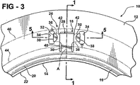
接続構造26はさらに、シム層18が取付けられる活動層12に形成される関連付けられる開口部または装着窓34を含む。図3および図5に最もよく示されるように、窓34を介して延在し、取付けられる活動層12のオーバーラップ領域36のまわりでタブ32を効果的に包むために互いに向かって折り返されるベンドタブ32を受けるように、窓34はサイズ決めおよび位置決めされる。タブ32が折り返されるオーバーラップ領域36は、お互いからおよびタブ部分28のネック領域30から横方向に間隔をおかれる。オーバーラップ領域36はさらに、シム層18の環状部分20およびシム層18が取付けられる活動層12のシールエンボスメント16から間隔をおかれる。図3および図5に最もよ
く示されるように、ベンドタブ32の各々は、ネック領域30から横方向に間隔をおかれる各々の対応する窓34の端縁に折り線38を有し、その結果ベンドタブ38はネック領域30の上ではなくベンドタブ自体の上に折り重ねられる。窓34は好ましくは十分な広さを有するので、ベンドタブ32が最初にタブ部分28の平面で平坦な状態から窓34を介して上方向に折り曲げられ、シム層18が取付けられる活動層12のオーバーラップ領域36の上に折り返されることが可能である。
The
シム層18が取付けられる活動層12はさらに好ましくは、図3に最もよく図示されるように、軸Aに沿ってシールエンボスメント16の外側に径方向に延在し、タブ部分28の径方向に外側の端部を超えて延在する中央排気弁または緩衝窓40を含む。この緩衝窓40は好ましくは、タブ部分28のネック領域30よりわずかに広いが、折り返されるタブ32の端部から内側に間隔をおかれる。窓34、40は、シム層18が取付けられ、ベンドタブ32が折り重ねられる活動層12の比較的薄い締付け部分42を規定する。この締付け部分42は、タブ部分のネック領域30から間隔をおかれ、活動層12のオーバーラップ領域36を部分的に規定する。タブ部分46および窓34はしたがって、シム層18を活動層12に接続する役割を果たす。
The
この発明に従うガスケット10は、オープンデッキエンジンブロックおよびクローズドデッキエンジンブロックでの適用に使用可能である。図3の破鎖線44および46はオープンデッキでの適用に関して接続構造26の位置を表わし、44および46は境界線44、46の間の領域がオープンであり、接続構造26を支持しないようにトップデッキに延在するブロックのオープン燃焼室の側壁を表わす。ガスケット10がこのようなオープンデッキエンジンでの適用例のヘッドとブロックとの間で締付けられるとき、接続構造26はオープン領域に向かって下方向にたわむことが許され、したがってエンボスメント16の所望のシーリング特性を損なうであろうシールエンボスメント16へ戻る過度の抵抗もしくは応力を妨げないか、または導入しない。
The
この発明のガスケット10がクローズドデッキヘッドとブロックとの間で締付けられるとき(この場合、接続構造固体の上部および下部のヘッドならびにブロックに破鎖線44、46は存在しないであろう)、シールエンボスメント16は燃焼室のまわりにシールを形成するために圧縮され、折り返されるタブ32もまた圧縮される。狭い締付け部分42および中間緩衝窓40は、狭い締付け部分42、つまりお互いから間隔を置かれ、ネック領域30の軸Aから間隔をおかれる場所に型締め力を集中させる。この態様において、ベントタブ32の圧縮によって引起される任意の抵抗は非常に局在化され、タブ部分28の全幅にわたって広がらない。この局在化はさらに、シールエンボスメント16に伝えられるシーリング力にベントタブが与える影響を限定する。ベントタブ32の圧縮がタブ部分28の領域においてシールエンボスメント16の均一な締付けを乱すように作用する程度まで、型締め圧力のこのような任意の低減は締付け部分42に沿って放射状に非常に局在化され、締付け部分42はエンボスメント16のシーリング能力に最小の影響を与えるように非常に狭く、さらにお互いから間隔をおかれる。
When the
明らかに、この発明の多くの修正および変形が上記の教示の観点から可能である。したがって、特許請求の範囲内で、この発明は具体的に記載されるのとは異なるように実施されてもよいことが理解されるべきである。この発明は特許請求の範囲によって規定される。 Obviously, many modifications and variations of the present invention are possible in light of the above teachings. It is therefore to be understood that within the scope of the appended claims, the invention may be practiced otherwise than as specifically described. The invention is defined by the claims.
Claims (13)
少なくとも1つの活動層、少なくとも1つのシム層を含み、活動層およびシム層は整列する燃焼孔を有し、シム層は燃焼孔を取囲む環状部分および環状部分から放射状に外に向かって突き出るタブ部分を有し、環状部分は活動層のうちの少なくとも1つの活動層の、関連付けられるシーリングビードの下地をなし、タブ部分は外側の端部でネック領域から前記燃焼孔の周方向に外に向かって突き出る側面ベンドタブの組を支持する放射状に延在するネック領域を含み、前記ベンドタブは少なくとも1つの活動層に形成される前記燃焼孔の周方向に間隔をおかれる装着窓の、関連付けられる組を介して突き出て、シム層を少なくとも1つの活動層に固定するために前記ベンドタブ同士が互いに向かって折り返されており、前記少なくとも1つの活動層は前記装着窓の間にある前記ネック領域の軸に沿って存在する緩衝窓を含む、金属ガスケット。A multi-layer metal gasket,
At least one active layer, including at least one shim layer, the active layer and the shim layer having aligned combustion holes, the shim layer surrounding the combustion holes and a tab projecting radially outward from the annular portion The annular portion is the base of the associated sealing bead of at least one active layer of the active layer, and the tab portion is outward from the neck region in the circumferential direction of the combustion hole at the outer end. Including a radially extending neck region that supports a set of projecting side bend tabs, the bend tabs having associated sets of mounting windows spaced circumferentially of the combustion holes formed in at least one active layer. projecting through said Bendotabu each other in order to secure at least one active layer shim layer which is folded back towards each other, wherein at least one of Doso includes a buffer window lying along an axis of said neck region between said mounting windows, metal gaskets.
Applications Claiming Priority (5)
| Application Number | Priority Date | Filing Date | Title |
|---|---|---|---|
| US43287602P | 2002-12-12 | 2002-12-12 | |
| US60/432,876 | 2002-12-12 | ||
| US10/733,914 US6935635B2 (en) | 2002-12-12 | 2003-12-11 | Metal gasket |
| US10/733,914 | 2003-12-11 | ||
| PCT/US2003/039371 WO2004055418A2 (en) | 2002-12-12 | 2003-12-12 | Metal gasket |
Publications (2)
| Publication Number | Publication Date |
|---|---|
| JP2006515405A JP2006515405A (en) | 2006-05-25 |
| JP4740596B2 true JP4740596B2 (en) | 2011-08-03 |
Family
ID=33543987
Family Applications (1)
| Application Number | Title | Priority Date | Filing Date |
|---|---|---|---|
| JP2004560763A Expired - Fee Related JP4740596B2 (en) | 2002-12-12 | 2003-12-12 | Metal gasket |
Country Status (10)
| Country | Link |
|---|---|
| US (1) | US6935635B2 (en) |
| EP (1) | EP1573193B1 (en) |
| JP (1) | JP4740596B2 (en) |
| KR (1) | KR101111033B1 (en) |
| AT (1) | ATE503098T1 (en) |
| AU (1) | AU2003302246A1 (en) |
| DE (1) | DE60336502D1 (en) |
| MX (1) | MXPA05006273A (en) |
| RU (1) | RU2326255C2 (en) |
| WO (1) | WO2004055418A2 (en) |
Families Citing this family (15)
| Publication number | Priority date | Publication date | Assignee | Title |
|---|---|---|---|---|
| FR2830281B1 (en) * | 2001-09-28 | 2003-11-28 | Meillor Sa | CYLINDER HEAD GASKET COMPRISING AN EDGE-TO-EDGE STOPPER LINKED BY STAPLING |
| US20050189724A1 (en) * | 2004-02-26 | 2005-09-01 | Federal-Mogul Corporation | Metal gasket |
| EP1811162B1 (en) * | 2004-10-29 | 2014-06-04 | NIPPON LEAKLESS INDUSTRY Co., Ltd. | Metal gasket for cylinder head |
| JP4223023B2 (en) * | 2005-04-14 | 2009-02-12 | 石川ガスケット株式会社 | Cylinder head gasket |
| EP1734245B1 (en) * | 2005-06-16 | 2007-10-31 | Reinz-Dichtungs-Gmbh | Multi-layer metallic gasket |
| DE102005043630A1 (en) * | 2005-09-13 | 2007-03-22 | Federal-Mogul Sealing Systems Gmbh | Metallic flat gasket |
| DE102006014386A1 (en) * | 2006-03-29 | 2007-10-11 | Elringklinger Ag | Flat gasket, in particular cylinder head gasket |
| US7694978B2 (en) * | 2006-08-08 | 2010-04-13 | Federal-Mogul World Wide, Inc. | Gasket assembly and method of manufacture thereof |
| DE202006018649U1 (en) * | 2006-12-09 | 2007-03-08 | Heinrich Gillet Gmbh | Collecting flange e.g. for cylinder heads of internal combustion engines, has collecting housing, tube connection flange and for each cylinder single flange is provided having attachment mechanism |
| DE102007032785B4 (en) * | 2007-07-13 | 2010-02-25 | Federal-Mogul Sealing Systems Gmbh | Cylinder head gasket with individual sealing elements |
| DE102008006675A1 (en) * | 2008-01-30 | 2009-08-13 | Federal-Mogul Sealing Systems Gmbh | gasket |
| DE102012100919A1 (en) * | 2012-02-03 | 2013-08-08 | Elringklinger Ag | Metallic flat gasket |
| US8833330B2 (en) | 2012-12-13 | 2014-09-16 | Caterpillar Inc. | Method of manufacturing an engine block |
| US20140165396A1 (en) * | 2012-12-13 | 2014-06-19 | Caterpillar Inc. | Self-centering seal |
| CA2959750A1 (en) * | 2014-09-04 | 2016-03-10 | Dana Automotive Systems Group, Llc | Gasket having upper and lower active layers and a spacer layer |
Citations (3)
| Publication number | Priority date | Publication date | Assignee | Title |
|---|---|---|---|---|
| JPH0281968A (en) * | 1988-09-20 | 1990-03-22 | Matsushita Refrig Co Ltd | Supporting device for rotary compressor |
| US6062573A (en) * | 1998-05-21 | 2000-05-16 | Dana Corporation | Gasket seal having an improved attachment element |
| JP2002286141A (en) * | 2001-03-23 | 2002-10-03 | Nichias Corp | Metal gasket |
Family Cites Families (4)
| Publication number | Priority date | Publication date | Assignee | Title |
|---|---|---|---|---|
| US1771596A (en) * | 1927-09-16 | 1930-07-29 | Victor Mfg & Gasket Co | Gasket |
| ES2077976T3 (en) * | 1991-02-19 | 1995-12-01 | Ishikawa Gasket | LAMINATED METAL JOINT, WITH FIXING DEVICES. |
| JPH10184916A (en) * | 1996-12-20 | 1998-07-14 | Nippon Gasket Co Ltd | Metallic gasket |
| US20060027124A1 (en) * | 2004-03-30 | 2006-02-09 | Sclafani Procopio J | Non-lethal shotgun round with foam liner |
-
2003
- 2003-12-11 US US10/733,914 patent/US6935635B2/en not_active Expired - Lifetime
- 2003-12-12 AT AT03810064T patent/ATE503098T1/en not_active IP Right Cessation
- 2003-12-12 WO PCT/US2003/039371 patent/WO2004055418A2/en active Application Filing
- 2003-12-12 RU RU2005121901/06A patent/RU2326255C2/en not_active IP Right Cessation
- 2003-12-12 JP JP2004560763A patent/JP4740596B2/en not_active Expired - Fee Related
- 2003-12-12 EP EP03810064A patent/EP1573193B1/en not_active Expired - Lifetime
- 2003-12-12 MX MXPA05006273A patent/MXPA05006273A/en active IP Right Grant
- 2003-12-12 DE DE60336502T patent/DE60336502D1/en not_active Expired - Lifetime
- 2003-12-12 KR KR1020057010818A patent/KR101111033B1/en active IP Right Grant
- 2003-12-12 AU AU2003302246A patent/AU2003302246A1/en not_active Abandoned
Patent Citations (3)
| Publication number | Priority date | Publication date | Assignee | Title |
|---|---|---|---|---|
| JPH0281968A (en) * | 1988-09-20 | 1990-03-22 | Matsushita Refrig Co Ltd | Supporting device for rotary compressor |
| US6062573A (en) * | 1998-05-21 | 2000-05-16 | Dana Corporation | Gasket seal having an improved attachment element |
| JP2002286141A (en) * | 2001-03-23 | 2002-10-03 | Nichias Corp | Metal gasket |
Also Published As
| Publication number | Publication date |
|---|---|
| EP1573193A2 (en) | 2005-09-14 |
| DE60336502D1 (en) | 2011-05-05 |
| US20040262850A1 (en) | 2004-12-30 |
| US6935635B2 (en) | 2005-08-30 |
| MXPA05006273A (en) | 2006-03-08 |
| AU2003302246A1 (en) | 2004-07-09 |
| KR20050113597A (en) | 2005-12-02 |
| WO2004055418A3 (en) | 2004-12-29 |
| EP1573193A4 (en) | 2010-07-07 |
| AU2003302246A8 (en) | 2004-07-09 |
| KR101111033B1 (en) | 2012-02-17 |
| EP1573193B1 (en) | 2011-03-23 |
| JP2006515405A (en) | 2006-05-25 |
| RU2005121901A (en) | 2006-01-20 |
| ATE503098T1 (en) | 2011-04-15 |
| RU2326255C2 (en) | 2008-06-10 |
| WO2004055418A2 (en) | 2004-07-01 |
Similar Documents
| Publication | Publication Date | Title |
|---|---|---|
| JP4740596B2 (en) | Metal gasket | |
| US8556271B2 (en) | Multilayer metal gasket | |
| WO2006046662A1 (en) | Metal gasket for cylinder head | |
| JP3026084B2 (en) | Metal gaskets for internal combustion engines | |
| US6139025A (en) | Metal laminate gasket with wide and narrow flange portions | |
| JP3290104B2 (en) | Metal laminated gasket | |
| JP3057443B1 (en) | Metal gasket with bore | |
| EP1098114B1 (en) | Metal gasket assembly for cylinder head | |
| US6969072B2 (en) | Cylinder head gasket with fold-over stopper | |
| JP4041684B2 (en) | Metal gasket | |
| JPH08178070A (en) | Cylinder head gasket | |
| JPH075320Y2 (en) | Metal gasket | |
| JP3098734B2 (en) | Metal laminated gasket | |
| JP2522140Y2 (en) | Rubber coated metal gasket | |
| JPH04219572A (en) | Metal gasket | |
| JP2954929B2 (en) | Metal gasket | |
| JPH10196790A (en) | Cylinder head gasket | |
| JP3960441B2 (en) | Cylinder head gasket for internal combustion engine | |
| JP3364577B2 (en) | gasket | |
| JPS6342203Y2 (en) | ||
| JPH0417881Y2 (en) | ||
| JPH0536137Y2 (en) | ||
| JP2597303Y2 (en) | Metallic gasket for cylinder head | |
| JP2002323135A (en) | Single-layer metal gasket | |
| CN100366884C (en) | Metal gasket |
Legal Events
| Date | Code | Title | Description |
|---|---|---|---|
| A621 | Written request for application examination |
Free format text: JAPANESE INTERMEDIATE CODE: A621 Effective date: 20060928 |
|
| A131 | Notification of reasons for refusal |
Free format text: JAPANESE INTERMEDIATE CODE: A131 Effective date: 20091201 |
|
| A521 | Request for written amendment filed |
Free format text: JAPANESE INTERMEDIATE CODE: A523 Effective date: 20100226 |
|
| A131 | Notification of reasons for refusal |
Free format text: JAPANESE INTERMEDIATE CODE: A131 Effective date: 20100824 |
|
| A601 | Written request for extension of time |
Free format text: JAPANESE INTERMEDIATE CODE: A601 Effective date: 20101122 |
|
| A602 | Written permission of extension of time |
Free format text: JAPANESE INTERMEDIATE CODE: A602 Effective date: 20101130 |
|
| A521 | Request for written amendment filed |
Free format text: JAPANESE INTERMEDIATE CODE: A523 Effective date: 20101217 |
|
| TRDD | Decision of grant or rejection written | ||
| A01 | Written decision to grant a patent or to grant a registration (utility model) |
Free format text: JAPANESE INTERMEDIATE CODE: A01 Effective date: 20110405 |
|
| A61 | First payment of annual fees (during grant procedure) |
Free format text: JAPANESE INTERMEDIATE CODE: A61 Effective date: 20110502 |
|
| R150 | Certificate of patent or registration of utility model |
Ref document number: 4740596 Country of ref document: JP Free format text: JAPANESE INTERMEDIATE CODE: R150 Free format text: JAPANESE INTERMEDIATE CODE: R150 |
|
| FPAY | Renewal fee payment (event date is renewal date of database) |
Free format text: PAYMENT UNTIL: 20140513 Year of fee payment: 3 |
|
| R250 | Receipt of annual fees |
Free format text: JAPANESE INTERMEDIATE CODE: R250 |
|
| R250 | Receipt of annual fees |
Free format text: JAPANESE INTERMEDIATE CODE: R250 |
|
| R250 | Receipt of annual fees |
Free format text: JAPANESE INTERMEDIATE CODE: R250 |
|
| R250 | Receipt of annual fees |
Free format text: JAPANESE INTERMEDIATE CODE: R250 |
|
| R250 | Receipt of annual fees |
Free format text: JAPANESE INTERMEDIATE CODE: R250 |
|
| R250 | Receipt of annual fees |
Free format text: JAPANESE INTERMEDIATE CODE: R250 |
|
| LAPS | Cancellation because of no payment of annual fees |