JP4740491B2 - Sample processing equipment - Google Patents
Sample processing equipment Download PDFInfo
- Publication number
- JP4740491B2 JP4740491B2 JP2001251467A JP2001251467A JP4740491B2 JP 4740491 B2 JP4740491 B2 JP 4740491B2 JP 2001251467 A JP2001251467 A JP 2001251467A JP 2001251467 A JP2001251467 A JP 2001251467A JP 4740491 B2 JP4740491 B2 JP 4740491B2
- Authority
- JP
- Japan
- Prior art keywords
- holder
- container
- station
- processing
- reagent
- Prior art date
- Legal status (The legal status is an assumption and is not a legal conclusion. Google has not performed a legal analysis and makes no representation as to the accuracy of the status listed.)
- Expired - Lifetime
Links
- 238000012545 processing Methods 0.000 title claims description 34
- 239000003153 chemical reaction reagent Substances 0.000 claims description 38
- 238000005485 electric heating Methods 0.000 claims description 15
- 239000002184 metal Substances 0.000 claims description 9
- 230000002380 cytological effect Effects 0.000 claims description 7
- 238000012546 transfer Methods 0.000 claims description 5
- 238000012360 testing method Methods 0.000 claims description 3
- 238000010438 heat treatment Methods 0.000 description 19
- 238000010186 staining Methods 0.000 description 8
- 230000007246 mechanism Effects 0.000 description 5
- 230000009471 action Effects 0.000 description 4
- 238000006243 chemical reaction Methods 0.000 description 4
- 239000011810 insulating material Substances 0.000 description 4
- 239000004020 conductor Substances 0.000 description 3
- 238000005338 heat storage Methods 0.000 description 3
- 239000000919 ceramic Substances 0.000 description 2
- 230000000694 effects Effects 0.000 description 2
- 238000003780 insertion Methods 0.000 description 2
- 230000037431 insertion Effects 0.000 description 2
- 238000009434 installation Methods 0.000 description 2
- 238000009413 insulation Methods 0.000 description 2
- 239000007788 liquid Substances 0.000 description 2
- 230000005855 radiation Effects 0.000 description 2
- 229920003002 synthetic resin Polymers 0.000 description 2
- 239000000057 synthetic resin Substances 0.000 description 2
- 238000011109 contamination Methods 0.000 description 1
- 230000008878 coupling Effects 0.000 description 1
- 238000010168 coupling process Methods 0.000 description 1
- 238000005859 coupling reaction Methods 0.000 description 1
- 230000001419 dependent effect Effects 0.000 description 1
- 238000005265 energy consumption Methods 0.000 description 1
- 230000017525 heat dissipation Effects 0.000 description 1
- 230000004048 modification Effects 0.000 description 1
- 238000012986 modification Methods 0.000 description 1
Images
Classifications
-
- G—PHYSICS
- G01—MEASURING; TESTING
- G01N—INVESTIGATING OR ANALYSING MATERIALS BY DETERMINING THEIR CHEMICAL OR PHYSICAL PROPERTIES
- G01N1/00—Sampling; Preparing specimens for investigation
- G01N1/28—Preparing specimens for investigation including physical details of (bio-)chemical methods covered elsewhere, e.g. G01N33/50, C12Q
- G01N1/30—Staining; Impregnating ; Fixation; Dehydration; Multistep processes for preparing samples of tissue, cell or nucleic acid material and the like for analysis
- G01N1/31—Apparatus therefor
- G01N2001/315—Basket-type carriers for tissues
-
- Y—GENERAL TAGGING OF NEW TECHNOLOGICAL DEVELOPMENTS; GENERAL TAGGING OF CROSS-SECTIONAL TECHNOLOGIES SPANNING OVER SEVERAL SECTIONS OF THE IPC; TECHNICAL SUBJECTS COVERED BY FORMER USPC CROSS-REFERENCE ART COLLECTIONS [XRACs] AND DIGESTS
- Y10—TECHNICAL SUBJECTS COVERED BY FORMER USPC
- Y10T—TECHNICAL SUBJECTS COVERED BY FORMER US CLASSIFICATION
- Y10T436/00—Chemistry: analytical and immunological testing
- Y10T436/11—Automated chemical analysis
- Y10T436/112499—Automated chemical analysis with sample on test slide
Description
【0001】
【発明の属する技術分野】
本発明は、複数の処理ステーションと、被検物を処理ステーションに導入し且つ処理ステーションから引出すための好ましくは1つの移送装置とを有し、被検物、特に、細胞学的または組織学的試料を処理する装置に関する。
【0002】
【従来の技術】
単に例としてヨーロッパ特許EP0849582B1を挙げる。この公報には、被検物、特に、細胞学的または組織学的試料を処理する上述の種類の装置が記載されている。この場合、細胞学的または組織学的試料は、被検物ホルダまたはケージによって自動染色機構に送られる。この場合、自動染色機構は、複数の処理ステーションを含む。
【0003】
ヨーロッパ特許EP0849582B1に記載の上述の種類の装置は、異なる処理ステーションを含むが、この処理ステーションは、従来の試薬ステーションと考えられる。この場合、試薬の作用を助成するまたは反応プロセスを助成するための十分な方策は、取られていない。
【0004】
【発明が解決しようとする課題】
さて、本発明の課題は、染色、試薬の作用または、更には、反応プロセスを助成できるよう、被検物、特に、細胞学的または組織学的試料(ないし標本)を処理する装置を構成、改良することにある。
【0005】
【課題を解決するための手段】
上記課題は、請求項1の特徴によって解決される。即ち、本発明の一視点によれば、複数の処理ステーションと、被検物を処理ステーションに導入し且つ処理ステーションから引出すための移送装置とを有し、細胞学的または組織学的試料等の被検物を処理する装置において、処理ステーションとして、複数の容器を含むことのできる加熱可能な少なくとも1つの試薬ステーションが設けてあること、試薬ステーションが、複数の容器を受容する断熱性ホルダを含み、該ホルダには、複数の容器を装入するまたは差込む複数の凹みが設けてあり、該ホルダが、複数の凹みに付設して複数の電気加熱装置を含んでいること、及び、前記電気加熱装置が、相互に無関係に作動することを特徴とする。
【0006】
【発明の実施の形態】
装置は、容器が、伝熱性が良好で、又は更に、蓄熱性の基部を有し、基部には、金属ブロックとして構成された電気加熱装置が組込んであることが好ましい。
装置は、試薬ステーションが、容器を受容する断熱性ホルダを含み、ホルダには、容器を装入するまたは差込む凹みが設けてあり、この場合、ホルダが、電気加熱装置を含み、加熱装置が、ホルダに組込まれた電気加熱プレートとして構成されていることが好ましい。
装置は、容器の受容に役立つホルダが、槽内に設置でき、槽が、ホルダを受容、ロックする保持手段を有することが好ましい。
装置は、試薬ステーションが、補足の処理ステーションとして設けられていることが好ましい。
装置は、試薬ステーションが、従来の処理ステーションと交換するために設けられていることが好ましい。
装置は、合計2つの好ましくは並置された試薬ステーションが設けられていることが好ましい。
装置は、試薬ステーションが、従来の処理ステーションの容器と同様の寸法を有する容器を含むことが好ましい。
装置は、容器壁部が、断熱材料から作製されていることが好ましい。
装置は、容器壁部が、合成樹脂またはセラミックから作製されていることが好ましい。
装置は、容器が、熱伝導性材料から作製されていることが好ましい。
装置は、容器が、金属から作成されていることが好ましい。
装置は、容器壁部が、断熱材によって囲まれていることが好ましい。
装置は、ホルダが、2つまたはより多数の容器を受容するよう構成されていることが好ましい。
装置は、ホルダが、相互に無関係に作動する2つまたはより多数の加熱装置を含むことが好ましい。
装置は、槽が、電気加熱装置の接続のため、電気接続を有することが好ましい。
装置は、槽が、とりわけ排出管路に接続される排出スタッドの形の排出口を有することが好ましい。
細胞学的または組織学的試料等の被検物を処理する装置、とりわけ自動染色機構に使用される装置に配される、加熱可能な試薬ステーションも好ましい。
【0007】
本発明にもとづき、試薬ステーションを加熱可能に構成することによって、試薬の作用態様、即ち、例えば、組織試料の染色を助成でき、しかも、反応プロセスを助成できるということが認識された。この場合、すべての処理ステーションを加熱する必要はなく、更には、個別の加熱装置を処理装置に設ける必要もない。加熱可能な唯一つの試薬ステーションまたは加熱可能な所定数の試薬ステーションの設置で十分であり、かくして、上記試薬ステーション内部において“特殊処理”を行うことができる。
【0008】
有利な態様で、試薬ステーションを補足の処理ステーションとして設けることができる。この場合、本来の処理ステーションの前方、側方または後方の配置が必要であるか、このような配置が可能である。これに関する自由スペースを用意しなければならない。
【0009】
しかしながら、更に、従来の処理ステーションと交換するために、試薬ステーションを設けることも考えられ、かくして、加熱可能な試薬ステーションを後から容易に装備できる。加熱装置の電気接続は、装置のハウジング外から導入でき、従って、更なる組込作業は不要である。更に、電気接続は、ハウジングに直接に設けることも考えられる。この場合、ハウジングから加熱可能な試薬ステーションに至る不動の電気接続路または配線が必要である。
【0010】
特に装置の十分なフレキシビリティの実現のため、合計2つの試薬ステーションを並置するか順次に配置すれば有利である。更なる加熱可能な試薬ステーションの設置方策も考えられる。この場合、対象となる試薬ステーションの実際の数は、実際の要求に適合させなければならない。
【0011】
具体的に、試薬ステーションは、従来の処理ステーションの容器と同様の寸法を有する容器を含むことができる。この限りにおいて、簡単な交換が可能であり、この場合、加熱または給電を確保しなければならない。
【0012】
容器または容器壁部を断熱材料から作製でき、かくして、外部への過度に急速な放熱を避けることができる。加熱装置は、−加熱ロッドと同様−容器内に設置できるか、容器の壁部または底部に組込むことができる。容器壁部は、合成樹脂またはセラミックから作製できる。
【0013】
上述の実施例とは異なり、内方への−液体への−伝熱が促進されるよう、容器を熱伝導性材料から作製できる。この限りにおいて、容器を金属から作製できる。外方への熱放射を減少するため、容器壁部を断熱材によって囲むことができ、かくして、容器は、魔法瓶と同様に働く。
【0014】
容器は、特に有利な態様で、容器は、熱伝導性良好で、又は更に、蓄熱性の底部を有し、この場合、上記基部は、容器の底部を形成する金属ブロックとして構成できる。この限りにおいて、容器の蓄熱性が助成される。
【0015】
容器内部に電気加熱装置、即ち、例えば、加熱ロッドを組込むことができることは、既に述べた。しかしながら、更に、金属ブロックとして構成された基部に加熱装置を組込むことも考えられ、かくして、基部から熱を−直接的熱交換によって−液体または試薬に伝達できる。この場合、対応する電気接続を容器に設ける。この場合、差込結合が、特に好適である。
【0016】
有利な態様で、試薬ステーションは、容器を受容するための、好ましくは、断熱性のホルダを有することができる。ホルダ内部には、容器の挿入または差込みのための凹みを構成できる。更に有利な態様で、ホルダは、好ましい実施例の枠内でホルダに組込んだ電気加熱プレートとして構成できる電気加熱装置を含むことができる。対応して、ホルダは、同じく差込結合の形に構成できる電気接続を介して接合しなければならない。
【0017】
−場合によっては、加熱装置を備えた−ホルダは、2つまたはより多数の容器を同時に受容するよう構成できる。この場合、ホルダは、このために、受容すべき容器の数に対応して凹み(好ましくは対応する容器の数だけの凹み)を有する。この場合、ホルダに挿入したすべての容器を唯一つの加熱装置によって同時に加熱できる。請求の装置のできる限り高いフレキシビリティを得るため、ホルダは、相互に無関係に作動する2つまたはより多数の加熱装置を含むことができ、かくして、各容器を単独で加熱できる。この場合、1つの容器だけに装填した場合は、加熱が必要なのはこの容器のみであり、このような加熱を実施できる。かくして、消費エネルギが、明らかに減少される。
【0018】
特に、ハウジング内への容器からのオーバフローを避けるためまたは使用試薬による不測な汚染を避けるため、試薬ステーション、特に、容器の受容に役立つホルダを槽内に設置する。この場合、−1つまたは2つの処理ステーションの補充のための−他の処理ステーションの代わりに槽をハウジングに挿入できる。何れの場合も、槽は、特に、1つまたは複数の容器を挿入するホルダを受容し、場合によっては、ロックする保持手段を有することができる。電気加熱装置の接続のため、槽は、電気接続を有することができ、かくして、大きな改造作業を要することなく、直接の電気接続が可能である。
【0019】
更に、槽は、好ましくは、排出管路に接続される排出スタッドの形の排出口を有することができ、かくして、オーバフローした試薬またはこぼれた試薬を排出できる。槽内に設けた検知器は、槽の充填レベルを検知でき、所定の−クリティカルな−槽充填レベルに達した場合、警報を発生できる。
【0020】
更に、温度設定値を考慮して調節が可能なよう、加熱装置自体または加熱プレート、ホルダまたは槽に1つまたは複数の温度センサを装備できることが判っている。この限りにおいて、容器内にある液温の調節を行い得るよう、容器内に温度センサを設けることができる。加熱装置の調節または制御のために、一体のまたは別個の制御ユニットを設けることができる。対応する制御ユニットを後から装置に装備することができる。この場合、後からの装備を簡単化するため、外部の設置も考えられる。
【0021】
さて、本発明の教示を有利な態様に構成、改良する各種の方策がある。これに関して、一方では、請求項1に続く請求項を挙げ、他方では、図面を参照する本発明の実施例の以下の説明を挙げる。図面を参照する本発明の好ましい実施例の説明に関連して、教示の好ましい構成および改良を総合的に説明する。なお、請求の範囲に付した図面参照符号は、発明の理解の容易化のために過ぎず、本発明を図示の態様に限定することは意図しない。
【0022】
【実施例】
図1および図2の何れにも、本発明に係る装置にまたは自動染色機構に処理ステーションとして使用できる加熱可能な試薬ステーションを示した。
【0023】
ここで選択した実施例の場合、従来の処理ステーションと交換して試薬ステーション1が設けてある。この場合、試薬ステーション1は、容器2を含むことができる。ここで選択した実施例において2つの容器2を使用する場合、上記容器は、並置する。
【0024】
容器2は、その寸法に関して、従来の処理ステーションの容器と同様に構成されており、従って、−特に、所要スペースに鑑みて−簡単な交換が可能である。
【0025】
ここで選択した実施例の場合、容器2は、熱伝導性材料、正確に云えば、金属から作製されている。容器2は、底部範囲に、金属ブロックとして構成された熱伝導性良好で蓄熱性の基部3を有する。基部3は、下面に平坦面を備えており、従って、平坦な台に対する面接触が可能である。
【0026】
双方の図面に詳細に示した如く、試薬ステーション1は、容器2を受容するホルダ4を有する。ホルダ4は、断熱性材料から作製されているので、容器2の下部範囲において、特に、基部3の範囲において、外部への放熱は著しく減少される。
【0027】
ホルダ4は、2つの容器の挿入または差込みのため、合計2つの凹み5を有する。この場合、図面には、1つの容器2のみを示した。
【0028】
容器2は、更に、電気加熱プレートとしてホルダ4に組込んだ電気加熱装置を含む。電気接続が設けてあるが、図示してない。
【0029】
ここで具体的に選択した実施例の場合、容器2の平坦に構成された基部は、同じく平坦に構成された加熱プレート6と面接触し、従って、加熱プレート6から容器2の基部3への最適な伝熱が可能である。
【0030】
最後に特に強調するが、上述の実施例は、請求の教示の模範的な説明に役立つが、上記教示は、上記実施例に限定されるものではない。
【0031】
【発明の効果】
本発明の基本構成(請求項1)により、所期の効果が達成される。即ち、被検物の処理装置において、染色、試薬の作用または、更には、反応プロセスを助成できるように、構成できる。さらに、各従属請求項の特徴によって、夫々、付加的な利点が達成される。
【図面の簡単な説明】
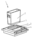
【図1】特に自動染色機構に使用するための、本発明に係る装置の加熱可能な試薬ステーションの実施例の斜視図である。
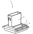
【図2】容器を挿入した状態の図1の対象の図面である。
【符号の説明】
1 加熱可能な試薬ステーション
2 容器
3 (容器の)基部,金属ブロック
4 (容器の)ホルダ
5 (ホルダの)凹み
6 (ホルダの)電気加熱プレート[0001]
BACKGROUND OF THE INVENTION
The present invention comprises a plurality of processing stations and preferably one transfer device for introducing and withdrawing the specimen from the processing station, and the specimen, in particular cytological or histological. The present invention relates to an apparatus for processing a sample.
[0002]
[Prior art]
Just as an example, mention is made of European patent EP0849582B1. This publication describes a device of the type described above for processing a specimen, in particular a cytological or histological sample. In this case, the cytological or histological sample is sent to the automatic staining mechanism by means of a specimen holder or cage. In this case, the automatic staining mechanism includes a plurality of processing stations.
[0003]
An apparatus of the above-mentioned type described in European patent EP0849582B1 includes a different processing station, which is considered a conventional reagent station. In this case, sufficient measures have not been taken to support the action of the reagents or to support the reaction process.
[0004]
[Problems to be solved by the invention]
Now, the object of the present invention is to construct an apparatus for processing a specimen, particularly a cytological or histological sample (or specimen), so as to be able to support staining, the action of a reagent, or even a reaction process, There is to improve.
[0005]
[Means for Solving the Problems]
The object is solved by the features of claim 1. That is, according to an aspect of the present invention includes a plurality of processing stations, the transfer feed device for drawing from and processing station by introducing a specimen into the processing station, cytological or histological specimen, such as an apparatus for processing a specimen of, as a processing station, thermal insulation holder that at least one reagent station heatable multiple containers can free Mukoto is provided, the reagent station, for receiving a plurality of containers The holder is provided with a plurality of recesses for inserting or inserting a plurality of containers, and the holder includes a plurality of electric heating devices attached to the plurality of recesses, and The electric heating devices operate independently of each other .
[0006]
DETAILED DESCRIPTION OF THE INVENTION
In the apparatus, it is preferable that the container has good heat conductivity or further has a heat storage base portion, and an electric heating device configured as a metal block is incorporated in the base portion.
The apparatus includes an insulative holder in which the reagent station receives a container, the holder being provided with a recess for inserting or inserting the container, in which case the holder includes an electric heating device, It is preferably configured as an electric heating plate incorporated in the holder.
The apparatus preferably has a holder that serves to receive the container in the tank, the tank having holding means for receiving and locking the holder.
The apparatus is preferably provided with a reagent station as a supplementary processing station.
The apparatus is preferably provided for the reagent station to be replaced with a conventional processing station.
The apparatus is preferably provided with a total of two preferably juxtaposed reagent stations.
The apparatus preferably includes a container where the reagent station has dimensions similar to those of a conventional processing station.
In the apparatus, the container wall is preferably made of a heat insulating material.
In the apparatus, the container wall is preferably made of synthetic resin or ceramic.
In the device, the container is preferably made from a thermally conductive material.
In the apparatus, the container is preferably made of metal.
In the apparatus, the container wall is preferably surrounded by a heat insulating material.
The apparatus is preferably configured so that the holder receives two or more containers.
Preferably, the apparatus includes two or more heating devices in which the holder operates independently of each other.
It is preferred that the apparatus has an electrical connection for the connection of the electric heating device in the vessel.
The device preferably has a discharge outlet in the form of a discharge stud, in particular connected to the discharge line.
Preference is also given to heatable reagent stations which are arranged in devices for processing specimens such as cytological or histological samples, in particular devices used in automatic staining mechanisms.
[0007]
In accordance with the present invention, it has been recognized that by configuring the reagent station to be heatable, the mode of action of the reagent, i.e., for example, staining of a tissue sample, can be facilitated and the reaction process can be facilitated. In this case, it is not necessary to heat all the processing stations, and it is not necessary to provide a separate heating device in the processing apparatus. The installation of only one heatable reagent station or a predetermined number of heatable reagent stations is sufficient and thus a “special treatment” can be carried out inside the reagent station.
[0008]
In an advantageous manner, the reagent station can be provided as a supplementary processing station. In this case, an arrangement in front, side or rear of the original processing station is necessary or possible. There must be free space for this.
[0009]
However, it is also conceivable to provide a reagent station to replace the conventional processing station, so that a heatable reagent station can easily be provided later. The electrical connection of the heating device can be introduced from outside the housing of the device, so that no further assembly work is necessary. It is also conceivable for the electrical connection to be provided directly on the housing. In this case, a stationary electrical connection or wiring from the housing to the heatable reagent station is required.
[0010]
In particular, in order to achieve sufficient flexibility of the apparatus, it is advantageous to arrange a total of two reagent stations side by side or sequentially. Further measures for installing a heatable reagent station are also conceivable. In this case, the actual number of reagent stations of interest must be adapted to the actual requirements.
[0011]
Specifically, the reagent station can include a container having dimensions similar to those of a conventional processing station. In this way, a simple exchange is possible, in which case heating or power supply must be ensured.
[0012]
The container or container wall can be made of a heat insulating material, thus avoiding excessively rapid heat dissipation to the outside. The heating device—as well as the heating rod—can be installed in the container or incorporated into the wall or bottom of the container. The container wall can be made of synthetic resin or ceramic.
[0013]
Unlike the embodiments described above, the container can be made from a thermally conductive material so that heat transfer inward—to liquid—is facilitated. To this extent, the container can be made from metal. In order to reduce outward heat radiation, the container wall can be surrounded by thermal insulation, thus the container acts like a thermos.
[0014]
In a particularly advantageous manner, the container has a good thermal conductivity or additionally a heat-storing bottom, in which case the base can be configured as a metal block that forms the bottom of the container. To this extent, the heat storage properties of the container are subsidized.
[0015]
It has already been mentioned that an electrical heating device, i.e. for example a heating rod, can be incorporated inside the container. However, it is also conceivable to incorporate a heating device in the base configured as a metal block, so that heat can be transferred from the base—by direct heat exchange—to a liquid or reagent. In this case, a corresponding electrical connection is provided on the container. In this case, plug-in coupling is particularly suitable.
[0016]
In an advantageous manner, the reagent station may have a preferably insulating holder for receiving the container. A recess for inserting or inserting the container can be formed inside the holder. In a further advantageous manner, the holder can comprise an electric heating device which can be configured as an electric heating plate incorporated in the holder within the frame of the preferred embodiment. Correspondingly, the holder must be joined via an electrical connection which can also be configured in the form of a plug-in connection.
[0017]
-In some cases, with a heating device-the holder can be configured to receive two or more containers simultaneously. In this case, the holder has for this purpose a recess corresponding to the number of containers to be received (preferably as many as the corresponding number of containers). In this case, all the containers inserted in the holder can be heated simultaneously by a single heating device. In order to obtain the highest possible flexibility of the claimed device, the holder can include two or more heating devices operating independently of each other, thus allowing each container to be heated independently. In this case, when only one container is loaded, only this container needs to be heated, and such heating can be performed. Thus, the energy consumption is clearly reduced.
[0018]
In particular, in order to avoid overflow from the container into the housing or inadvertent contamination by the reagents used, a reagent station, in particular a holder that serves to receive the container, is installed in the tank. In this case-for replenishment of one or two processing stations-the tank can be inserted into the housing instead of the other processing stations. In any case, the basin can in particular have a holding means for receiving and possibly locking a holder for inserting one or more containers. Due to the connection of the electrical heating device, the bath can have an electrical connection, and thus a direct electrical connection is possible without requiring major modification work.
[0019]
In addition, the tank can preferably have a discharge port in the form of a discharge stud connected to the discharge line, thus allowing overflowed or spilled reagents to be discharged. A detector provided in the tank can detect the filling level of the tank and can generate an alarm when a predetermined-critical-tank filling level is reached.
[0020]
Furthermore, it has been found that the heating device itself or the heating plate, holder or bath can be equipped with one or more temperature sensors so that adjustments can be made taking into account the temperature setpoint. In this case, a temperature sensor can be provided in the container so that the temperature of the liquid in the container can be adjusted. An integral or separate control unit can be provided for adjustment or control of the heating device. A corresponding control unit can later be installed in the device. In this case, external installation is also conceivable in order to simplify the equipment afterwards.
[0021]
There are various ways to construct and improve the teachings of the present invention in an advantageous manner. In this connection, on the one hand, the claims following claim 1 are given, on the other hand, the following description of embodiments of the invention with reference to the drawings. In connection with the description of the preferred embodiment of the present invention with reference to the drawings, preferred configurations and improvements of the teachings are generally described. Note that the reference numerals of the drawings attached to the claims are only for facilitating the understanding of the invention, and are not intended to limit the present invention to the illustrated embodiment.
[0022]
【Example】
Both FIG. 1 and FIG. 2 show a heatable reagent station that can be used as a processing station in an apparatus according to the invention or in an automatic staining mechanism.
[0023]
In the case of the embodiment selected here, a reagent station 1 is provided in place of the conventional processing station. In this case, the reagent station 1 can include a
[0024]
The
[0025]
In the case of the embodiment chosen here, the
[0026]
As shown in detail in both figures, the reagent station 1 has a
[0027]
The
[0028]
The
[0029]
In the case of the embodiment specifically selected here, the flatly configured base of the
[0030]
Finally, particularly emphasized, the above-described embodiments serve to exemplary explanation of the claimed teachings, but the teachings are not limited to the above-described embodiments.
[0031]
【The invention's effect】
According to the basic configuration of the present invention (claim 1), the desired effect is achieved. In other words, the treatment apparatus for the test object can be configured so that the staining, the action of the reagent, or further, the reaction process can be supported. Furthermore, additional advantages are achieved in each case by the features of the dependent claims.
[Brief description of the drawings]
FIG. 1 is a perspective view of an embodiment of a heatable reagent station of an apparatus according to the present invention, particularly for use in an automatic staining mechanism.
FIG. 2 is a drawing of the subject of FIG. 1 with a container inserted.
[Explanation of symbols]
1
Claims (4)
処理ステーションとして、複数の容器(2)を含むことのできる加熱可能な少なくとも1つの試薬ステーション(1)が設けてあること、
試薬ステーション(1)が、複数の容器(2)を受容する断熱性ホルダ(4)を含み、該ホルダ(4)には、複数の容器(2)を装入するまたは差込む複数の凹み(5)が設けてあり、該ホルダ(4)が、複数の凹み(5)に付設して複数の電気加熱装置を含んでいること、及び、
前記電気加熱装置が、相互に無関係に作動すること
を特徴とする処理装置。In an apparatus for processing a test object such as a cytological or histological sample, having a plurality of processing stations and a transfer device for introducing the test object into the processing station and withdrawing from the processing station,
As a processing station, the at least one reagent station heatable multiple containers (2) can containing Mukoto (1) is provided,
The reagent station (1) includes an insulative holder (4) for receiving a plurality of containers (2), wherein the holder (4) has a plurality of recesses for loading or inserting a plurality of containers (2) ( 5), the holder (4) includes a plurality of electric heating devices attached to the plurality of recesses (5), and
The processing apparatus , wherein the electric heating devices operate independently of each other .
Applications Claiming Priority (2)
| Application Number | Priority Date | Filing Date | Title |
|---|---|---|---|
| DE10041227.0 | 2000-08-22 | ||
| DE10041227A DE10041227B4 (en) | 2000-08-22 | 2000-08-22 | Device for the treatment of objects |
Publications (3)
| Publication Number | Publication Date |
|---|---|
| JP2002116202A JP2002116202A (en) | 2002-04-19 |
| JP2002116202A5 JP2002116202A5 (en) | 2008-07-31 |
| JP4740491B2 true JP4740491B2 (en) | 2011-08-03 |
Family
ID=7653421
Family Applications (1)
| Application Number | Title | Priority Date | Filing Date |
|---|---|---|---|
| JP2001251467A Expired - Lifetime JP4740491B2 (en) | 2000-08-22 | 2001-08-22 | Sample processing equipment |
Country Status (5)
| Country | Link |
|---|---|
| US (1) | US6756015B2 (en) |
| JP (1) | JP4740491B2 (en) |
| CN (1) | CN1196922C (en) |
| DE (1) | DE10041227B4 (en) |
| GB (1) | GB2366377B (en) |
Families Citing this family (8)
| Publication number | Priority date | Publication date | Assignee | Title |
|---|---|---|---|---|
| DE10223304B4 (en) | 2002-05-24 | 2018-12-13 | Leica Biosystems Nussloch Gmbh | Device for embedding samples in paraffin |
| KR20040023999A (en) * | 2002-09-12 | 2004-03-20 | 엘지전자 주식회사 | structure of motor shaft in clothes dryer |
| JPWO2004053482A1 (en) * | 2002-12-12 | 2006-04-13 | 財団法人新産業創造研究機構 | Microbial rapid staining method and microorganism rapid staining apparatus |
| US8236255B2 (en) * | 2004-12-02 | 2012-08-07 | Lab Vision Corporation | Slide treatment apparatus and methods for use |
| US7875242B2 (en) * | 2006-10-17 | 2011-01-25 | Preyas Sarabhai Shah | Slide stainer with multiple heater stations |
| US20090253163A1 (en) * | 2008-04-02 | 2009-10-08 | General Electric Company | Iterative staining of biological samples |
| DE102008023660B4 (en) * | 2008-04-21 | 2010-02-11 | Hirt Zerspanungstechnik Gmbh | Device for heating an object by means of a water bath |
| AU2013202808B2 (en) | 2012-07-31 | 2014-11-13 | Gen-Probe Incorporated | System and method for performing multiplex thermal melt analysis |
Family Cites Families (27)
| Publication number | Priority date | Publication date | Assignee | Title |
|---|---|---|---|---|
| GB712766A (en) * | 1951-10-15 | 1954-07-28 | Harold Faraday Barnard | An automatic tissue processor for histology |
| US3350220A (en) * | 1963-07-12 | 1967-10-31 | Technicon Company Inc | Tissue processing for electron microscope examination thereof |
| US3762362A (en) * | 1971-09-01 | 1973-10-02 | J Lipshaw | Automatic tissue processor |
| GB1405940A (en) * | 1972-11-10 | 1975-09-10 | Sakura Finetechnical Co Ltd | Apparatus for processing tissue for electron microscope examination |
| US3807353A (en) * | 1972-11-29 | 1974-04-30 | Devco Inc | Tissue staining and processing machine |
| GB1453226A (en) * | 1974-01-30 | 1976-10-20 | Newman Howells Associates Ltd | Apparatus for the treatment or processing of histological and other specimens or apparatus |
| US4199558A (en) * | 1976-04-07 | 1980-04-22 | Shandon Southern Products Limited | Tissue processing method |
| US4092952A (en) * | 1977-08-19 | 1978-06-06 | Wilkie Ronald N | Automatic slide stainer |
| DE2939582A1 (en) * | 1979-09-29 | 1981-04-09 | Hoechst Ag, 6000 Frankfurt | METHOD AND Embedding System For Embedding Tissue Samples |
| US4651671A (en) * | 1986-02-21 | 1987-03-24 | Pedersen Anders N | Continuous feed apparatus for staining specimens carried on slides |
| US4911098A (en) * | 1987-12-28 | 1990-03-27 | Shiraimatsu & Co., Ltd. | Automatic straining apparatus for slide specimens |
| JP3058938B2 (en) * | 1991-04-09 | 2000-07-04 | 株式会社千代田製作所 | Dyeing equipment and tray for dyeing |
| DE4117830A1 (en) * | 1991-05-29 | 1992-12-03 | Medite Ges Fuer Medizintechnik | Histological preparation colour treatment station trough - has heating elements mounted on or integrated into trough and temp. sensors connected to controller |
| DE4117833C2 (en) * | 1991-05-29 | 1993-10-07 | Medite Ges Fuer Medizintechnik | Method and device for staining histological specimens arranged on slides |
| US6180061B1 (en) * | 1992-05-11 | 2001-01-30 | Cytologix Corporation | Moving platform slide stainer with heating elements |
| JPH08500434A (en) * | 1992-05-13 | 1996-01-16 | オーストラリアン バイオメディカル コーポレーション リミテッド | Automatic staining device for slide specimens |
| US6387326B1 (en) * | 1994-07-19 | 2002-05-14 | Fisher Scientific Company L.L.C. | Automated slide staining system and method thereof |
| JPH08327513A (en) * | 1995-06-01 | 1996-12-13 | Aloka Co Ltd | Organic tissue treatment device |
| NO954650D0 (en) * | 1995-11-17 | 1995-11-17 | Torstein Ljungmann | Color machine for staining tissue samples on slides |
| JPH09250974A (en) * | 1996-03-14 | 1997-09-22 | Aloka Co Ltd | Apparatus for treating biological tissue |
| JPH1019749A (en) * | 1996-06-28 | 1998-01-23 | Aloka Co Ltd | Living tissue processor |
| DE19647662C1 (en) * | 1996-11-19 | 1998-03-12 | Leica Instr Gmbh | Operating drive for automatic histological sample handling device |
| DE19652339A1 (en) * | 1996-12-17 | 1998-06-18 | Microm Laborgeraete Gmbh | Device for treating objects |
| AUPO439496A0 (en) * | 1996-12-24 | 1997-01-23 | Australian Biomedical Corporation Pty. Ltd. | Smearer mechanism |
| NO306357B1 (en) * | 1997-10-16 | 1999-10-25 | Torstein Ljungmann | Color machine for preparation of tissue samples placed on slides |
| US6183693B1 (en) * | 1998-02-27 | 2001-02-06 | Cytologix Corporation | Random access slide stainer with independent slide heating regulation |
| AU763354B2 (en) * | 1998-02-27 | 2003-07-17 | Ventana Medical Systems, Inc. | Automated molecular pathology apparatus having independent slide heaters |
-
2000
- 2000-08-22 DE DE10041227A patent/DE10041227B4/en not_active Expired - Lifetime
-
2001
- 2001-08-02 GB GB0118885A patent/GB2366377B/en not_active Expired - Lifetime
- 2001-08-16 US US09/931,138 patent/US6756015B2/en not_active Expired - Lifetime
- 2001-08-22 CN CNB011257768A patent/CN1196922C/en not_active Expired - Lifetime
- 2001-08-22 JP JP2001251467A patent/JP4740491B2/en not_active Expired - Lifetime
Also Published As
| Publication number | Publication date |
|---|---|
| CN1196922C (en) | 2005-04-13 |
| CN1339699A (en) | 2002-03-13 |
| GB2366377A (en) | 2002-03-06 |
| GB2366377B (en) | 2002-11-27 |
| DE10041227B4 (en) | 2011-12-29 |
| US20020025276A1 (en) | 2002-02-28 |
| JP2002116202A (en) | 2002-04-19 |
| DE10041227A1 (en) | 2002-03-07 |
| US6756015B2 (en) | 2004-06-29 |
| GB0118885D0 (en) | 2001-09-26 |
Similar Documents
| Publication | Publication Date | Title |
|---|---|---|
| US5061630A (en) | Laboratory apparatus for optional temperature-controlled heating and cooling | |
| JP4740491B2 (en) | Sample processing equipment | |
| CA2616673C (en) | System comprising a plurality of incubators | |
| CN106536711B (en) | Modular incubator system | |
| JP2006058003A (en) | Superheated steam cooker | |
| EP0273969A1 (en) | Temperature control apparatus for automated clinical analyzer. | |
| JP2007033460A (en) | Polarimeter | |
| JP2759558B2 (en) | Boiling water dispenser with improved water temperature control system | |
| CN212819999U (en) | Automatic concentration instrument | |
| US6518059B1 (en) | High efficiency microplate incubator | |
| US4680945A (en) | Cooling chamber for processing specimens for microscopic and electron-microscopic investigations | |
| US7854903B2 (en) | Reaction chamber system for processing samples | |
| CN101589915A (en) | Beverage container warmer | |
| JP3108895U (en) | Cryostat with heating device | |
| JP2714837B2 (en) | Reagent bottle table temperature controller | |
| JP4149949B2 (en) | Electric pot | |
| CN218422892U (en) | Heat-conducting piece and heating device comprising same | |
| CN220110123U (en) | Sterilizing cabinet | |
| CN220292199U (en) | Heating device and cell culture equipment | |
| CN219363669U (en) | Experimental device for be used for stem cell culture | |
| CN214453556U (en) | Asphalt inspection device | |
| CN215940014U (en) | Test sample bottle keeps warm and controls box | |
| EP4290241A1 (en) | Sample measuring apparatus | |
| CN213993223U (en) | Cooking utensil | |
| CN219065051U (en) | Multi-aperture partition temperature control graphite digestion instrument for ICP |
Legal Events
| Date | Code | Title | Description |
|---|---|---|---|
| A621 | Written request for application examination |
Free format text: JAPANESE INTERMEDIATE CODE: A621 Effective date: 20080527 |
|
| A521 | Written amendment |
Free format text: JAPANESE INTERMEDIATE CODE: A523 Effective date: 20080612 |
|
| A977 | Report on retrieval |
Free format text: JAPANESE INTERMEDIATE CODE: A971007 Effective date: 20100805 |
|
| A131 | Notification of reasons for refusal |
Free format text: JAPANESE INTERMEDIATE CODE: A131 Effective date: 20100810 |
|
| A521 | Written amendment |
Free format text: JAPANESE INTERMEDIATE CODE: A523 Effective date: 20101109 |
|
| TRDD | Decision of grant or rejection written | ||
| A01 | Written decision to grant a patent or to grant a registration (utility model) |
Free format text: JAPANESE INTERMEDIATE CODE: A01 Effective date: 20110426 |
|
| A01 | Written decision to grant a patent or to grant a registration (utility model) |
Free format text: JAPANESE INTERMEDIATE CODE: A01 |
|
| A61 | First payment of annual fees (during grant procedure) |
Free format text: JAPANESE INTERMEDIATE CODE: A61 Effective date: 20110502 |
|
| R150 | Certificate of patent or registration of utility model |
Ref document number: 4740491 Country of ref document: JP Free format text: JAPANESE INTERMEDIATE CODE: R150 Free format text: JAPANESE INTERMEDIATE CODE: R150 |
|
| FPAY | Renewal fee payment (event date is renewal date of database) |
Free format text: PAYMENT UNTIL: 20140513 Year of fee payment: 3 |
|
| R250 | Receipt of annual fees |
Free format text: JAPANESE INTERMEDIATE CODE: R250 |
|
| R250 | Receipt of annual fees |
Free format text: JAPANESE INTERMEDIATE CODE: R250 |
|
| R250 | Receipt of annual fees |
Free format text: JAPANESE INTERMEDIATE CODE: R250 |
|
| R250 | Receipt of annual fees |
Free format text: JAPANESE INTERMEDIATE CODE: R250 |
|
| R250 | Receipt of annual fees |
Free format text: JAPANESE INTERMEDIATE CODE: R250 |
|
| R250 | Receipt of annual fees |
Free format text: JAPANESE INTERMEDIATE CODE: R250 |
|
| R250 | Receipt of annual fees |
Free format text: JAPANESE INTERMEDIATE CODE: R250 |
|
| R250 | Receipt of annual fees |
Free format text: JAPANESE INTERMEDIATE CODE: R250 |
|
| EXPY | Cancellation because of completion of term |