JP4740467B2 - Control of ridge load and air / oil seal temperature in turbines - Google Patents
Control of ridge load and air / oil seal temperature in turbines Download PDFInfo
- Publication number
- JP4740467B2 JP4740467B2 JP2001107878A JP2001107878A JP4740467B2 JP 4740467 B2 JP4740467 B2 JP 4740467B2 JP 2001107878 A JP2001107878 A JP 2001107878A JP 2001107878 A JP2001107878 A JP 2001107878A JP 4740467 B2 JP4740467 B2 JP 4740467B2
- Authority
- JP
- Japan
- Prior art keywords
- turbine
- air
- blower
- oil seal
- controlling
- Prior art date
- Legal status (The legal status is an assumption and is not a legal conclusion. Google has not performed a legal analysis and makes no representation as to the accuracy of the status listed.)
- Expired - Fee Related
Links
Images
Classifications
-
- F—MECHANICAL ENGINEERING; LIGHTING; HEATING; WEAPONS; BLASTING
- F02—COMBUSTION ENGINES; HOT-GAS OR COMBUSTION-PRODUCT ENGINE PLANTS
- F02C—GAS-TURBINE PLANTS; AIR INTAKES FOR JET-PROPULSION PLANTS; CONTROLLING FUEL SUPPLY IN AIR-BREATHING JET-PROPULSION PLANTS
- F02C9/00—Controlling gas-turbine plants; Controlling fuel supply in air- breathing jet-propulsion plants
-
- F—MECHANICAL ENGINEERING; LIGHTING; HEATING; WEAPONS; BLASTING
- F01—MACHINES OR ENGINES IN GENERAL; ENGINE PLANTS IN GENERAL; STEAM ENGINES
- F01D—NON-POSITIVE DISPLACEMENT MACHINES OR ENGINES, e.g. STEAM TURBINES
- F01D5/00—Blades; Blade-carrying members; Heating, heat-insulating, cooling or antivibration means on the blades or the members
- F01D5/02—Blade-carrying members, e.g. rotors
- F01D5/06—Rotors for more than one axial stage, e.g. of drum or multiple disc type; Details thereof, e.g. shafts, shaft connections
- F01D5/066—Connecting means for joining rotor-discs or rotor-elements together, e.g. by a central bolt, by clamps
-
- F—MECHANICAL ENGINEERING; LIGHTING; HEATING; WEAPONS; BLASTING
- F01—MACHINES OR ENGINES IN GENERAL; ENGINE PLANTS IN GENERAL; STEAM ENGINES
- F01D—NON-POSITIVE DISPLACEMENT MACHINES OR ENGINES, e.g. STEAM TURBINES
- F01D25/00—Component parts, details, or accessories, not provided for in, or of interest apart from, other groups
- F01D25/08—Cooling; Heating; Heat-insulation
- F01D25/12—Cooling
- F01D25/125—Cooling of bearings
-
- F—MECHANICAL ENGINEERING; LIGHTING; HEATING; WEAPONS; BLASTING
- F01—MACHINES OR ENGINES IN GENERAL; ENGINE PLANTS IN GENERAL; STEAM ENGINES
- F01D—NON-POSITIVE DISPLACEMENT MACHINES OR ENGINES, e.g. STEAM TURBINES
- F01D5/00—Blades; Blade-carrying members; Heating, heat-insulating, cooling or antivibration means on the blades or the members
- F01D5/02—Blade-carrying members, e.g. rotors
- F01D5/08—Heating, heat-insulating or cooling means
- F01D5/081—Cooling fluid being directed on the side of the rotor disc or at the roots of the blades
-
- F—MECHANICAL ENGINEERING; LIGHTING; HEATING; WEAPONS; BLASTING
- F01—MACHINES OR ENGINES IN GENERAL; ENGINE PLANTS IN GENERAL; STEAM ENGINES
- F01D—NON-POSITIVE DISPLACEMENT MACHINES OR ENGINES, e.g. STEAM TURBINES
- F01D9/00—Stators
- F01D9/06—Fluid supply conduits to nozzles or the like
- F01D9/065—Fluid supply or removal conduits traversing the working fluid flow, e.g. for lubrication-, cooling-, or sealing fluids
Landscapes
- Engineering & Computer Science (AREA)
- Mechanical Engineering (AREA)
- General Engineering & Computer Science (AREA)
- Physics & Mathematics (AREA)
- Fluid Mechanics (AREA)
- Chemical & Material Sciences (AREA)
- Combustion & Propulsion (AREA)
- Structures Of Non-Positive Displacement Pumps (AREA)
- Turbine Rotor Nozzle Sealing (AREA)
- Control Of Turbines (AREA)
Abstract
Description
【0001】
【発明の属する技術分野】
本発明は、発電用陸上ガスタービンなどのタービンに関し、特に、空気/オイルシールの高温に起因する軸受けの火災を防止しつつ、さねはぎ荷重を維持するために、排気送風機の質量流量を制御する方法に関する。
【0002】
【従来の技術】
典型的なガスタービンにおいては、回転子ホイールとスぺーサを重ね合わせることによりタービン回転子を形成し、重ね合わされた複数のホイールとスぺーサを相互にボルトで固定している。さねはぎ継手は、通常、スぺーサとホイールとの間に設けられる。
【0003】
【発明が解決しようとする課題】
標準燃焼運転停止中、第4段ホイールと後部軸との間のさねはぎ継手は、絶えず稼動している軸受け排気送風機からの冷却が高速で行われているために無荷重状態となり、その結果、間隙が形成される。さねはぎ継手が開いてしまうか、又は無荷重状態になると、各部品は相対的に動き、そのために、回転子は平衡を失い、大きな振動を引き起こす可能性があるので、高いコストと長い時間を要する平衡回復の作業や、回転子の交換が必要になるであろう。回転子の平衡の欠如は動作の上で許容されるものではなく、通常、設計技師は、そのような平衡の欠如が起こらないようにあらゆる努力をする。これに対し、運転停止中に軸受け排気送風機をオフした場合には、前部空気/オイルシールの温度が「ソークバック」現象によって最大設計実施基準を超える。空気/オイルシールの温度が設定最大設計限界を越えると、その結果、軸受けが発火し、機械に極めて重大な打撃を与えるであろう。
【0004】
【課題を解決するための手段】
本発明の一実施例では、タービンを動作させる方法は、既存のタービン構成要素によってタービンの熱パラメータを制御することにより、空気/オイルシールの温度を許容しうる低さに維持しつつ、さねはぎ継手の荷重を維持することからなる。この工程は、タービン排気フレームを横切る空気の質量流量を制御することにより実施すれればよい。この意味で、タービン構成要素は排気送風機であり、且つ空気の質量流量は排気送風機の速度を制御することにより制御されるのが好ましい。
【0005】
本発明の別の実施例では、タービンは、さねはぎ継手を間に挟んで互いに固定され且つ互いに軸方向に整列しているタービンホイールと、後部軸とを含む。タービンホイールと後部軸は加えられる温度に対して異なる応答を示すので、過渡状態で熱不整合を生じる。タービンを動作させる方法は、タービン構成要素の特性に従ってタービン構成要素の熱力学モデルを決定する工程と、この熱力学モデルに従ってタービン排気フレームを横切る空気の質量流量を制御する工程とを含む。構成要素の特性の例としては、動作温度、質量、密度、相対位置、速度などがある。
【0006】
本発明の更に別の実施例においては、後部軸に隣接して配設された第4段ホイールを含むタービンを動作させる方法は、第4段ホイールと後部軸との間のさねはぎ継手の近傍でタービン送風機の速度を制御し、それにより、さねはぎ継手の冷却速度を制御する工程を含む。
【0007】
【発明の実施の形態】
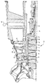
図1を参照すると、全体を図中符号10で示されたタービン回転子を含むタービンの一部が示されている。タービン回転子は、例えば、4段タービン回転子の部品を形成する回転子ホイール12、14、16及び18などの要素を重ね合わせた構造を有し、それらのホイールの間にはスぺーサ20、22及び24が交互に挟み込まれている。ホイール要素とスぺーサ要素は、回転子内部で複数の細長く、周囲方向に沿って延出するボルトによって一体に保持されていることがわかるであろう。尚、図1には1つのボルト26のみが示されている。ホイール12、14、16、18は、それぞれ、複数の周囲方向に沿って互いに離間したタービンバケット12a、14a、16a、18aを装着している。ノズル30、32、34、36はバケット12a、14a、16a、18aと共にそれぞれ段を形成している。ホイールとスぺーサは相互に軸方向に整列して位置しており、ホイールとスぺーサとの間にはさねはぎ継手が設けられている。この実施例のさねはぎ継手40は、図示されているように、最終段ホイール18と、後部軸44の一部を形成する後部軸ホイール42との間にある。さねはぎ継手はタービンの全動作範囲にわたって相互に係止状態に維持される。図示されているように、後部軸44は後部軸受け46の内部で回転子10と共に回転自在である。 タービンの動作中、特に運転停止時及びタービンの始動時には、回転子の様々な要素間に熱不整合が起こる。通常、機械は絶えず稼動している軸受け排気送風機48を含む。タービンが定常状態で動作しているとき、タービンの様々な要素間における温度分布は所定の範囲内の熱不整合しか示さないので、タービンの動作に悪影響が及ぶとは考えられない。しかし、過渡的動作(すなわち、運転停止時及び始動時)の間は、排気送風機48からの冷却の速度が速いために熱不整合は著しく大きくなり、これに対処しなければならない。例えば、後部軸ホイール42と最終段、例えば、第4段のホイール18との間にあるさねはぎ継手40は、許容しうる熱不整合をはるかに越えるような著しく大きな熱不整合を生じる。そのように大きな熱不整合によって熱膨張と収縮の速度に差が発生するため、さねはぎは開いてしまうか、又は無荷重状態になることがある。この状態においては、要素は相対的に動き、その結果、回転子は平衡を失って大きな振動を引き起こすので、平衡状態を回復するというコストのかかる作業や、回転子の交換が必要になる。
【0008】
すなわち、運転停止中、様々なタービン段の高温ガス経路を流れる高温ガスと、ボア管冷却回路組み立て体を流れる蒸気の流れが停止する。ホイール18は質量が非常に大きく、タービンの定常状態動作中には高温に加熱されているので、ホイール18は後部軸ホイール42における熱損失と比較して非常にゆっくりとした速度で熱を失って行く。その結果、さねはぎ継手40では大きな熱不整合が起こるのである。
【0009】
この問題を修正しようとする試みの1つにおいては、タービンの運転停止時に、さねはぎ継手40における熱不整合に対抗するために、排気送風機48の動作を停止させることが可能であろう。しかし、この場合、運転停止時に排気送風機48をオフしてしまうと、前部空気/オイルシール50の温度は「ソークバック」によって最大設計実施基準をたやすく超えるおそれがある。空気/オイルシール50の温度が設定された最大設計限界を超えると、軸受けが発火し、機械に極めて大きな打撃を与える。
【0010】
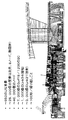
従って、過渡的状態の間に軸受け送風機により排出される排気の質量流量を制御することにより、さねはぎの荷重を許容限界に維持することができると共に、空気/オイルシールの温度を設定限界以下に維持することができる。タービン排気フレームを横切る空気の質量流量の制御は、排気送風機48の速度を制御することにより実現される。送風機の速度は、機械の各構成要素の物理的な面及び機械的な面の特性である機械の熱力学的特性に基づいて決定されるプロファイルに従い、時間の経過に伴って変化する。図2に示すような展開された詳細全流れ物理モデルを使用して、軸受け送風機48のスケジュールをどのようにすれば、所望の成果が実現されるかを決定するために、温度及び機械的特性の両面で基線燃焼運転停止過渡状態を解析することができる。図2は、General Electric Model7Hガスタービン設計の熱力学モデルの一例を示す。このモデルは、例えば、650の全(静止部品及び回転部品)物理流体要素と、25,000個の2次元熱固体要素と、40,000個のノードと、1,200個の境界条件を伴う7,000個の表面要素と、1,000個の伝導熱伝達リンクと、繰り返しごとに100秒の3,000個の放射熱伝達リンクとを含む、機械の詳細な部品ごとの熱力学的構造解析を含んでいる。図2に示すような熱力学モデルは言うまでもなく機械ごとに異なり、前述のように、図2に示すモデルは単なる一例である。
【0011】
図2に示す例の熱力学モデルのような熱力学モデルを使用して、空気/オイルシール50を許容しうる低温に維持しつつ、さねはぎ荷重を維持し且つさねはぎ継手を閉じた状態に維持するという設計基準に適合するように、排気送風機制御の許容プロファイル範囲を決定/最適化することができる。この点に関して、許容限界(すなわち、さねはぎ荷重の許容限界と、空気/オイルシールの温度の許容限界)の間に最大のマージンを与えるロバスト構成を獲得するために、統計プロセスを使用してプロファイルがモデルを通して試行し、最適化することができる。
【0012】
本発明の方法によれば、最適化した送風機プロファイルに従って軸受け送風機を厳密に制御することにより、タービンの過渡的段階(運転停止時又は始動時など)の間にさねはぎ荷重を許容限界に維持でき、また、空気/オイルシールの温度を設定限界以下に維持できる。後部軸冷却回路に空気を供給する送風機の流れを正確に制御することによって、プロセス能力はさねはぎ荷重とシール温度の双方について6シグマをたやすく超え、従って、さねはぎ継手における熱不整合は排除される。
【0013】
本発明を現時点で最も実用的で且つ好ましい実施例であると考えられるものに関連して説明したが、本発明は開示した実施例に限定されず、特許請求の範囲の趣旨に包含される様々な変形及び等価の構成を含むことを理解すべきである。
【図面の簡単な説明】
【図1】 タービンの一部の部分横断面図。
【図2】 熱力学モデルの決定を示すタービンの一例の図。
【符号の説明】
10…タービン回転子、12、14、16、18…回転子ホイール、40…さねはぎ継手、42…後部軸ホイール、44…後部軸、46…後部軸受け、48…排気送風機、50…空気/オイルシール[0001]
BACKGROUND OF THE INVENTION
The present invention relates to a turbine such as an onshore gas turbine for power generation, and in particular, controls the mass flow rate of an exhaust blower in order to maintain a toothed load while preventing a bearing fire due to the high temperature of an air / oil seal. On how to do.
[0002]
[Prior art]
In a typical gas turbine, a rotor rotor and a spacer are overlapped to form a turbine rotor, and a plurality of the overlapped wheels and spacers are fixed to each other with bolts. A tongue and groove joint is usually provided between the spacer and the wheel.
[0003]
[Problems to be solved by the invention]
During standard combustion shutdown, the tongue-and-groove joint between the 4th stage wheel and the rear shaft becomes unloaded because the cooling from the continuously operating bearing exhaust blower is performed at high speed. A gap is formed. When the tongue-and-groove joint opens or becomes unloaded, the parts move relative to each other, which can cause the rotor to lose balance and cause significant vibration, resulting in high cost and long time. It will be necessary to recover the balance and require replacement of the rotor. The lack of rotor balance is unacceptable in operation and design engineers usually make every effort to prevent such lack of balance. On the other hand, when the bearing exhaust blower is turned off during operation stop, the temperature of the front air / oil seal exceeds the maximum design implementation standard due to the “soak back” phenomenon. If the air / oil seal temperature exceeds the set maximum design limit, the resulting bearing will ignite and the machine will be severely hit.
[0004]
[Means for Solving the Problems]
In one embodiment of the present invention, a method for operating a turbine includes controlling the thermal parameters of a turbine with existing turbine components to maintain an air / oil seal temperature at an acceptable low level. It consists of maintaining the load on the seam joint. This step may be performed by controlling the mass flow rate of air across the turbine exhaust frame. In this sense, the turbine component is preferably an exhaust blower and the mass flow rate of air is preferably controlled by controlling the speed of the exhaust blower.
[0005]
In another embodiment of the present invention, the turbine includes a turbine wheel that is secured together and axially aligned with each other with a tongue and groove joint therebetween, and a rear shaft. The turbine wheel and the rear shaft exhibit different responses to the applied temperature, resulting in a thermal mismatch in the transient state. A method of operating a turbine includes determining a thermodynamic model of a turbine component according to the characteristics of the turbine component and controlling the mass flow rate of air across the turbine exhaust frame according to the thermodynamic model. Examples of component characteristics include operating temperature, mass, density, relative position, speed, and the like.
[0006]
In yet another embodiment of the present invention, a method of operating a turbine including a fourth stage wheel disposed adjacent to a rear shaft includes a tongue and groove joint between the fourth stage wheel and the rear shaft. Controlling the speed of the turbine blower in the vicinity, thereby controlling the cooling rate of the tongue and groove joint.
[0007]
DETAILED DESCRIPTION OF THE INVENTION
Referring to FIG. 1, there is shown a portion of a turbine that includes a turbine rotor, generally indicated at 10 in the figure. The turbine rotor has a structure in which elements such as
[0008]
That is, during shutdown, the hot gas flowing through the hot gas paths of the various turbine stages and the steam flow through the bore tube cooling circuit assembly are stopped. Since the
[0009]
In one attempt to correct this problem, it may be possible to stop the operation of the
[0010]
Therefore, by controlling the mass flow rate of the exhaust exhausted by the bearing blower during the transient state, it is possible to maintain the load of the tongue and groove at an allowable limit and to keep the air / oil seal temperature below the set limit. Can be maintained. Control of the mass flow rate of air across the turbine exhaust frame is achieved by controlling the speed of the
[0011]
A thermodynamic model, such as the example thermodynamic model shown in FIG. 2, was used to maintain the air /
[0012]
According to the method of the present invention, the shear fan load is maintained at an acceptable limit during a transient stage of the turbine (such as during shutdown or start-up) by strictly controlling the bearing fan according to the optimized fan profile. The temperature of the air / oil seal can be maintained below the set limit. By accurately controlling the flow of the blower supplying air to the rear shaft cooling circuit, the process capacity easily exceeds 6 sigma for both the sag load and the seal temperature, and therefore thermal mismatch at the sag joint. Is excluded.
[0013]
Although the present invention has been described in connection with what is considered to be the most practical and preferred embodiments at the present time, the invention is not limited to the disclosed embodiments and is intended to fall within the spirit of the claims. It should be understood that various modifications and equivalent arrangements are included.
[Brief description of the drawings]
FIG. 1 is a partial cross-sectional view of a portion of a turbine.
FIG. 2 is a diagram of an example turbine illustrating the determination of a thermodynamic model.
[Explanation of symbols]
DESCRIPTION OF
Claims (3)
Applications Claiming Priority (2)
| Application Number | Priority Date | Filing Date | Title |
|---|---|---|---|
| US09/635,086 US6379108B1 (en) | 2000-08-08 | 2000-08-08 | Controlling a rabbet load and air/oil seal temperatures in a turbine |
| US09/635086 | 2000-08-08 |
Publications (3)
| Publication Number | Publication Date |
|---|---|
| JP2002054458A JP2002054458A (en) | 2002-02-20 |
| JP2002054458A5 JP2002054458A5 (en) | 2008-05-15 |
| JP4740467B2 true JP4740467B2 (en) | 2011-08-03 |
Family
ID=24546390
Family Applications (1)
| Application Number | Title | Priority Date | Filing Date |
|---|---|---|---|
| JP2001107878A Expired - Fee Related JP4740467B2 (en) | 2000-08-08 | 2001-04-06 | Control of ridge load and air / oil seal temperature in turbines |
Country Status (7)
| Country | Link |
|---|---|
| US (1) | US6379108B1 (en) |
| EP (1) | EP1180577B1 (en) |
| JP (1) | JP4740467B2 (en) |
| KR (1) | KR100603077B1 (en) |
| AT (1) | ATE310154T1 (en) |
| CZ (1) | CZ2001546A3 (en) |
| DE (1) | DE60114950T2 (en) |
Families Citing this family (17)
| Publication number | Priority date | Publication date | Assignee | Title |
|---|---|---|---|---|
| US7493769B2 (en) * | 2005-10-25 | 2009-02-24 | General Electric Company | Assembly and method for cooling rear bearing and exhaust frame of gas turbine |
| US8801370B2 (en) * | 2006-10-12 | 2014-08-12 | General Electric Company | Turbine case impingement cooling for heavy duty gas turbines |
| GB2448116B (en) | 2007-04-05 | 2009-05-27 | Rolls Royce Plc | Means for cooling a bearing assembly |
| JP4969500B2 (en) * | 2008-03-28 | 2012-07-04 | 三菱重工業株式会社 | gas turbine |
| JP5148348B2 (en) * | 2008-04-16 | 2013-02-20 | 三菱重工業株式会社 | Turbine cooling structure, turbine and turbine assembly jig |
| US8090456B2 (en) * | 2008-11-03 | 2012-01-03 | United Technologies Corporation | System and method for design and control of engineering systems utilizing component-level dynamic mathematical model |
| US8315741B2 (en) * | 2009-09-02 | 2012-11-20 | United Technologies Corporation | High fidelity integrated heat transfer and clearance in component-level dynamic turbine system control |
| US8668434B2 (en) * | 2009-09-02 | 2014-03-11 | United Technologies Corporation | Robust flow parameter model for component-level dynamic turbine system control |
| US10094285B2 (en) | 2011-12-08 | 2018-10-09 | Siemens Aktiengesellschaft | Gas turbine outer case active ambient cooling including air exhaust into sub-ambient cavity |
| US9298173B2 (en) * | 2012-02-02 | 2016-03-29 | General Electric Company | System and method to performance tune a system |
| WO2014035441A1 (en) * | 2012-08-28 | 2014-03-06 | Mlcak Henry A | Adjustable systems and methods for increasing the efficiency of a kalina cycle |
| US9091171B2 (en) | 2012-10-30 | 2015-07-28 | Siemens Aktiengesellschaft | Temperature control within a cavity of a turbine engine |
| US9133868B2 (en) | 2013-04-16 | 2015-09-15 | General Electric Company | Fastener with radial loading |
| CN105960511B (en) * | 2013-11-08 | 2018-03-13 | 通用电气公司 | Gas turbine exhaust framework |
| US9784126B2 (en) | 2015-12-14 | 2017-10-10 | Hamilton Sundstrand Corporation | Variable-sized cooling air flow path |
| US10985608B2 (en) | 2016-12-13 | 2021-04-20 | General Electric Company | Back-up power system for a component and method of assembling same |
| JP2023100250A (en) * | 2022-01-05 | 2023-07-18 | ゼネラル・エレクトリック・カンパニイ | Exhaust frame differential cooling system |
Family Cites Families (24)
| Publication number | Priority date | Publication date | Assignee | Title |
|---|---|---|---|---|
| GB394001A (en) | 1931-12-18 | 1933-06-19 | Parsons C A & Co Ltd | Improvements in and relating to built-up rotors, suitable for steam turbines |
| GB635783A (en) | 1947-06-30 | 1950-04-19 | Frederic William Walton Morley | Improvements in or relating to turbine wheels and the like |
| US3713676A (en) * | 1971-05-07 | 1973-01-30 | Gen Electric | Predeformed rabbit joint |
| GB2090333B (en) | 1980-12-18 | 1984-04-26 | Rolls Royce | Gas turbine engine shroud/blade tip control |
| US4478553A (en) * | 1982-03-29 | 1984-10-23 | Mechanical Technology Incorporated | Isothermal compression |
| JPS59138731A (en) * | 1983-01-31 | 1984-08-09 | Hitachi Ltd | Controller for gas-turbine cooling air |
| JPS59173527A (en) * | 1983-03-22 | 1984-10-01 | Hitachi Ltd | Gas turbine exhaust frame cooling air system |
| DE3415165A1 (en) * | 1984-04-21 | 1985-10-31 | MTU Motoren- und Turbinen-Union München GmbH, 8000 München | DEVICE FOR REAL-TIME DETERMINATION OF THE TEMPERATURES AND THERMALLY CONDITIONAL MATERIAL STRESSES OF ROTATING PARTS OF MACHINES AND SYSTEMS IN OPERATION |
| JPS62193143A (en) * | 1986-02-19 | 1987-08-25 | Sanyo Electric Co Ltd | Manufacture of semiconductor integrated circuit device |
| FR2607866B1 (en) | 1986-12-03 | 1991-04-12 | Snecma | FIXING AXES OF TURBOMACHINE ROTORS, MOUNTING METHOD AND ROTORS THUS MOUNTED |
| US5403150A (en) * | 1988-04-28 | 1995-04-04 | Teledyne Industries, Inc. | Bearing insulating system for aircraft turbocharger |
| JPH029901A (en) | 1988-06-28 | 1990-01-12 | Toshiba Corp | Gas turbine rotor |
| US5281085A (en) | 1990-12-21 | 1994-01-25 | General Electric Company | Clearance control system for separately expanding or contracting individual portions of an annular shroud |
| US5288210A (en) * | 1991-10-30 | 1994-02-22 | General Electric Company | Turbine disk attachment system |
| US5292227A (en) * | 1992-12-10 | 1994-03-08 | General Electric Company | Turbine frame |
| DE4327376A1 (en) | 1993-08-14 | 1995-02-16 | Abb Management Ag | Compressor and method for its operation |
| US5622475A (en) * | 1994-08-30 | 1997-04-22 | General Electric Company | Double rabbet rotor blade retention assembly |
| DE4435322B4 (en) * | 1994-10-01 | 2005-05-04 | Alstom | Method and device for shaft seal and for cooling on the exhaust side of an axial flowed gas turbine |
| US5593274A (en) * | 1995-03-31 | 1997-01-14 | General Electric Co. | Closed or open circuit cooling of turbine rotor components |
| JPH11315800A (en) * | 1998-04-30 | 1999-11-16 | Toshiba Corp | Air compressor |
| US6146090A (en) * | 1998-12-22 | 2000-11-14 | General Electric Co. | Cooling/heating augmentation during turbine startup/shutdown using a seal positioned by thermal response of turbine parts and consequent relative movement thereof |
| JP4527824B2 (en) * | 1998-12-22 | 2010-08-18 | ゼネラル・エレクトリック・カンパニイ | Turbine rotor bearing cooling system |
| US6190127B1 (en) * | 1998-12-22 | 2001-02-20 | General Electric Co. | Tuning thermal mismatch between turbine rotor parts with a thermal medium |
| US6283712B1 (en) * | 1999-09-07 | 2001-09-04 | General Electric Company | Cooling air supply through bolted flange assembly |
-
2000
- 2000-08-08 US US09/635,086 patent/US6379108B1/en not_active Expired - Lifetime
-
2001
- 2001-02-13 CZ CZ2001546A patent/CZ2001546A3/en unknown
- 2001-04-04 KR KR1020010017897A patent/KR100603077B1/en active IP Right Grant
- 2001-04-06 JP JP2001107878A patent/JP4740467B2/en not_active Expired - Fee Related
- 2001-04-09 AT AT01303313T patent/ATE310154T1/en not_active IP Right Cessation
- 2001-04-09 DE DE60114950T patent/DE60114950T2/en not_active Expired - Lifetime
- 2001-04-09 EP EP01303313A patent/EP1180577B1/en not_active Expired - Lifetime
Also Published As
| Publication number | Publication date |
|---|---|
| JP2002054458A (en) | 2002-02-20 |
| EP1180577B1 (en) | 2005-11-16 |
| US6379108B1 (en) | 2002-04-30 |
| EP1180577A2 (en) | 2002-02-20 |
| KR100603077B1 (en) | 2006-07-20 |
| KR20020013371A (en) | 2002-02-20 |
| DE60114950D1 (en) | 2005-12-22 |
| DE60114950T2 (en) | 2006-07-27 |
| CZ2001546A3 (en) | 2002-03-13 |
| ATE310154T1 (en) | 2005-12-15 |
| EP1180577A3 (en) | 2003-10-08 |
Similar Documents
| Publication | Publication Date | Title |
|---|---|---|
| JP4740467B2 (en) | Control of ridge load and air / oil seal temperature in turbines | |
| JP4467112B2 (en) | Cooling / heating enhancement during turbine start / stop using seals positioned by the thermal response of the turbine parts and the relative movement of the parts accordingly | |
| US6190127B1 (en) | Tuning thermal mismatch between turbine rotor parts with a thermal medium | |
| JP3965607B2 (en) | Rotor assembly shroud | |
| EP2236747B1 (en) | Systems, methods, and apparatus for passive purge flow control in a turbine | |
| JP4150938B2 (en) | High temperature gas control structure for gas turbine | |
| EP2546471B1 (en) | Tip clearance control for turbine blades | |
| US8776533B2 (en) | Strain tolerant bound structure for a gas turbine engine | |
| US10329940B2 (en) | Method and system for passive clearance control in a gas turbine engine | |
| US20110027068A1 (en) | System and method for clearance control in a rotary machine | |
| US7128522B2 (en) | Leakage control in a gas turbine engine | |
| JPH01116251A (en) | Variable stator blade assembly | |
| JPH02245403A (en) | Compressor diaphragm assembly for combustion turbine and assembly method thereof | |
| EP2636851B1 (en) | Turbine assembly and method for supporting turbine components | |
| US20170130602A1 (en) | Method of operating a clearance control system | |
| EP3152405B1 (en) | Turbine, power generation system and method of assembling the turbine | |
| WO1997020131A1 (en) | Reducing steady state rotor blade tip clearance in a land-based gas turbine | |
| US20110255959A1 (en) | Turbine alignment control system and method | |
| JP2007009911A (en) | Cooled type gas turbine stator vane in gas turbine, use of gas turbine stator vane, and method for operation of gas turbine | |
| EP3904642B1 (en) | Improved turbomachinery heat transfer system | |
| Sugimoto et al. | Development of a 20MW-class high-efficiency gas turbine L20A | |
| KR102579798B1 (en) | Turbo Device | |
| Ryan et al. | A Unique Approach to HRSG Bypass Dampers |
Legal Events
| Date | Code | Title | Description |
|---|---|---|---|
| A521 | Request for written amendment filed |
Free format text: JAPANESE INTERMEDIATE CODE: A523 Effective date: 20080402 |
|
| A621 | Written request for application examination |
Free format text: JAPANESE INTERMEDIATE CODE: A621 Effective date: 20080402 |
|
| A131 | Notification of reasons for refusal |
Free format text: JAPANESE INTERMEDIATE CODE: A131 Effective date: 20100622 |
|
| A601 | Written request for extension of time |
Free format text: JAPANESE INTERMEDIATE CODE: A601 Effective date: 20100922 |
|
| RD02 | Notification of acceptance of power of attorney |
Free format text: JAPANESE INTERMEDIATE CODE: A7422 Effective date: 20100922 |
|
| RD04 | Notification of resignation of power of attorney |
Free format text: JAPANESE INTERMEDIATE CODE: A7424 Effective date: 20100922 |
|
| A602 | Written permission of extension of time |
Free format text: JAPANESE INTERMEDIATE CODE: A602 Effective date: 20100928 |
|
| A521 | Request for written amendment filed |
Free format text: JAPANESE INTERMEDIATE CODE: A523 Effective date: 20101222 |
|
| TRDD | Decision of grant or rejection written | ||
| A01 | Written decision to grant a patent or to grant a registration (utility model) |
Free format text: JAPANESE INTERMEDIATE CODE: A01 Effective date: 20110405 |
|
| A61 | First payment of annual fees (during grant procedure) |
Free format text: JAPANESE INTERMEDIATE CODE: A61 Effective date: 20110502 |
|
| R150 | Certificate of patent or registration of utility model |
Free format text: JAPANESE INTERMEDIATE CODE: R150 Ref document number: 4740467 Country of ref document: JP Free format text: JAPANESE INTERMEDIATE CODE: R150 |
|
| FPAY | Renewal fee payment (event date is renewal date of database) |
Free format text: PAYMENT UNTIL: 20140513 Year of fee payment: 3 |
|
| R250 | Receipt of annual fees |
Free format text: JAPANESE INTERMEDIATE CODE: R250 |
|
| R250 | Receipt of annual fees |
Free format text: JAPANESE INTERMEDIATE CODE: R250 |
|
| R250 | Receipt of annual fees |
Free format text: JAPANESE INTERMEDIATE CODE: R250 |
|
| R250 | Receipt of annual fees |
Free format text: JAPANESE INTERMEDIATE CODE: R250 |
|
| R250 | Receipt of annual fees |
Free format text: JAPANESE INTERMEDIATE CODE: R250 |
|
| LAPS | Cancellation because of no payment of annual fees |