JP4734958B2 - Medium storage device - Google Patents
Medium storage device Download PDFInfo
- Publication number
- JP4734958B2 JP4734958B2 JP2005049421A JP2005049421A JP4734958B2 JP 4734958 B2 JP4734958 B2 JP 4734958B2 JP 2005049421 A JP2005049421 A JP 2005049421A JP 2005049421 A JP2005049421 A JP 2005049421A JP 4734958 B2 JP4734958 B2 JP 4734958B2
- Authority
- JP
- Japan
- Prior art keywords
- screw
- storage device
- medium storage
- door
- release switch
- Prior art date
- Legal status (The legal status is an assumption and is not a legal conclusion. Google has not performed a legal analysis and makes no representation as to the accuracy of the status listed.)
- Expired - Fee Related
Links
Images


Description
本発明は、現金自動取引装置などに着脱自在に取り付けられ、紙幣等の媒体を収容し持ち運ぶ媒体収納装置に関するものである。 The present invention relates to a medium storage device that is detachably attached to an automatic teller machine or the like, and stores and carries a medium such as a bill.
従来より媒体収納装置には破壊や振動等を検出し警報を発生させるものがある。このような媒体収納装置では、電池を電源とした検出手段により破壊や振動等を検出し、警報出力の一手段としてインク等で紙幣や有価証券等を汚損させその価値を無効化するようにしている(例えば、特許文献1参照。)。 2. Description of the Related Art Conventionally, there are some media storage devices that generate an alarm by detecting destruction or vibration. In such a medium storage device, destruction or vibration is detected by a detection means using a battery as a power source, and banknotes, securities, etc. are defaced with ink or the like as a means for alarm output and the value is invalidated. (For example, refer to Patent Document 1).
一般に、以上のような電池やインク等には寿命があり、媒体収納装置を長期間使用する場合、これらの部品の交換が必要となる。また、これらの部品以外でも前記検出手段の部品が故障し、交換が必要となることがある。 In general, the above-described battery, ink, and the like have a lifetime, and when the medium storage device is used for a long period of time, it is necessary to replace these parts. In addition to these parts, parts of the detection means may fail and need to be replaced.
図9は、従来の媒体収納装置の概略斜視図であり、前述の保守作業を行うことを考慮し、媒体収納装置60内部の所定の位置に解除スイッチ61が設けられており、この解除スイッチ61を操作することにより破壊や振動等の検出手段の動作を停止し、警報発生、インク等での汚損機能のすべてを無効化できるようになっている。
FIG. 9 is a schematic perspective view of a conventional medium storage device, and a
この解除スイッチ61は、防犯のために、媒体収納装置60を取扱うことが出来る者だけが操作可能な場所で、保守を行う場所とは別の場所に設けるようにしている。そして、保守作業員は、解除スイッチ61を操作し、防犯検出部の機能を無効にし、誤った警報の発生、インク等での汚損動作が行われないようにしてから電池交換等の保守作業を開始するようにしている。
しかしながら、従来の媒体収納装置では、保守作業員の誤操作の恐れがあり、防犯検出部の機能を停止しないで作業をし、不要な警報を発生させたり、収納物を汚損してしまう恐れがあった。 However, with the conventional media storage device, there is a risk of maintenance operator's erroneous operation, and there is a risk of working without stopping the function of the security detection unit, generating an unnecessary alarm, or contaminating the stored items. It was.
また、通常運用時に、媒体収納装置60を取扱う係員などが、媒体収納装置60に媒体を収納するときに、誤って解除スイッチ61を操作してしまい、運用時に動作しないという恐れもあった。
Further, during normal operation, a staff member who handles the
本発明は、前述の課題を解決するため次の構成を採用する。すなわち、扉と防犯検出部を有する媒体収納装置において、前記防犯検出部のカバーを取り付けるためのネジ部を設け、前記ネジ部にネジを取り付けると防犯検出部の機能が有効となるようにした。 The present invention employs the following configuration in order to solve the above-described problems. That is, in a medium storage device having a door and a security detection part, a screw part for attaching the cover of the security detection part is provided, and the function of the security detection part becomes effective when a screw is attached to the screw part.
本発明の媒体収納装置によれば、防犯検出部のカバーを取り付ける際に、ネジが必要となる構成とし、ネジを取り付けることにより防犯検出部の機能を有効とするようにしたので、通常の運用では、防犯検出部の機能を確実に有効とすることができとともに、保守するときは、防犯検出部の機能を確実に解除することができる。 According to the medium storage device of the present invention, when the cover of the security detection unit is attached, a screw is required, and the function of the security detection unit is made effective by attaching the screw. Then, the function of the security detection unit can be surely enabled, and the function of the security detection unit can be reliably canceled when performing maintenance.
以下、本発明に係る実施の形態例を、図面を用いて説明する。なお図面に共通する要素には同一の符号を付す。なお、以下の実施例の説明では、便宜上、現金自動取引装置等にて一般に取扱われる紙幣を収納媒体の一例として説明する。 Embodiments of the present invention will be described below with reference to the drawings. In addition, the same code | symbol is attached | subjected to the element which is common in drawing. In the following description of the embodiments, for convenience, banknotes generally handled by an automatic teller machine will be described as an example of a storage medium.
実施例1の媒体収納装置は、防犯検出部のカバー取付用ネジの取り付けにより防犯検出部の機能を有効とし、前記ネジの取り外しにより防犯検出部の機能を解除するようにしたものである。 In the medium storage device of the first embodiment, the function of the security detection unit is made effective by attaching a cover mounting screw of the security detection unit, and the function of the security detection unit is canceled by removing the screw.
(構成)
図1は、現金自動取引装置の構成を示す外観斜視図であり、図2は、図1中の紙幣入出金部を示す斜視図である。図3は、図2にセットされる実施例1の媒体収納装置の外観を示す斜視図である。図4は、図3の内部構造の説明図である。
(Constitution)
FIG. 1 is an external perspective view showing a configuration of an automatic teller machine, and FIG. 2 is a perspective view showing a banknote deposit and withdrawal part in FIG. FIG. 3 is a perspective view illustrating an appearance of the medium storage device according to the first embodiment set in FIG. 2. FIG. 4 is an explanatory diagram of the internal structure of FIG.
図1に示したように、現金自動取引装置の接客側には、カード挿入口1、通帳入口2、顧客操作部3、ディスプレイ4、及び紙幣入出金口5等を有するパネル6が設けられている。現金自動取引装置の内部には、図2のような紙幣入出金部7が設けられている。
As shown in FIG. 1, on the customer service side of the automated teller machine, a panel 6 having a card insertion slot 1, a passbook entrance 2, a customer operation unit 3, a
紙幣入出金部7の上側には、紙幣入出金口5に連通する紙幣通行口8が形成されると共に紙幣処理部9が設けられている。紙幣入出金部7の下側には、収納部10が形成され、当該収納部10には例えば2台の媒体収納装置20が収納されるようになっている。
On the upper side of the banknote deposit /
2台のうち一方の媒体収納装置20は、例えば予備として用いられるものである。媒体収納装置20は、収納部10に対して着脱自在にセットされるものであり、例えば図3のように概ね直方体の箱体で、持ち運びを容易にするために、取っ手21が上部に設けられている。
One of the two
媒体収納装置20の一側面には、紙幣処理部9から挿入された紙幣が通過する2つの紙幣通過口22、23が形成され、他の側面には扉24が取り付けられるとともに当該扉24の施錠を行う鍵25が配置されている。
Two
媒体収納装置20の内部には、図4のように、紙幣を収納するための2つの紙幣収納部26、27が設けられている。紙幣収納部26は紙幣処理部9によって選別されて再び出金の必要のない紙幣が収納される収納部であり、紙幣収納部27は再び出金する可能性のある紙幣が収納される収納部である。
As shown in FIG. 4, two
そして、紙幣収納部26には、紙幣通過口22からガイドロール26aを介して紙幣が搬入されるようになっている。紙幣収納部27には、紙幣通過口23からガイドロール27aを介して紙幣が搬入及び搬出されるようになっている。
And a banknote is carried in into the
図5は、図3の媒体収納装置20に設けられた防犯検出部の構成を示す図である。扉24の内側には、蛇行する配線パターンからなる破壊センサ28aが形成され、箱体内部には扉24の開閉を検出する扉センサ28bが取り付けられ、鍵25には、ロックされたか否かを検出する鍵センサ29が取り付けられている。
FIG. 5 is a diagram illustrating a configuration of a security detection unit provided in the
破壊センサ28a及び扉センサ28bは、媒体収納装置20に対する破壊等の不正を検出する防犯センサ28であり、媒体収納装置20の内部には、不正があったことを示すために警報を発生したり、紙幣を使用不能に汚損する警報出力部30と、防犯検出部50全体をコントロールする防犯検出制御部35と、これらに電源を供給する電池31も組み込まれている。
The
警報出力部30と防犯検出制御部35と電池31は、媒体収納装置20の下側に設けられ、カバー36により覆われている。
The
図6は、実施例1の防犯検出部50の機能ブロック図である。電池31から電源供給を受ける破壊センサ28a及び扉センサ28bからなる防犯センサ28は、増幅器(アンプ)32を介して、マイクロコンピュータからなるCPU制御部(CPU)33に接続され、鍵センサ29は直接CPU制御部33に接続されている。CPU制御部33には防犯検出部50の機能を無効にすることが可能な解除スイッチ34が接続される。
FIG. 6 is a functional block diagram of the crime
解除スイッチ34は、カバー36の内部に設けられ、扉24を開けた状態でも操作できない構成となっている。そして、CPU制御部33の出力側に警報出力部30が接続されている。警報出力部30は、例えばブザーとインク噴出器等で構成されている。増幅器32、CPU制御部33及び警報出力部30も、電池31によって電源供給されるようになっている。
The
(動作)
以上の構成により、実施例1の媒体収納装置は、以下のように動作する。まず、通常の防犯監視動作として、CPU制御部33は、防犯センサ28及び鍵センサ29を用いて不正の有無を監視し、盗難を検知したときは、CPU制御部33は警報出力部30に制御信号を与え、ブザーを鳴らし、インクを噴射する等して紙幣を汚損するように動作する。
(Operation)
With the above configuration, the medium storage device of Embodiment 1 operates as follows. First, as a normal crime prevention monitoring operation, the
上記通常の防犯監視動作では、防犯センサ28、鍵センサ29及びCPU制御部33を駆動するための消費電力は非常に小さいが、長期間使用すればバッテリ容量が減少し電池電圧が低下し防犯検出制御部35が正常に動作しなくなる。また、警報出力部30が、例えばインク噴射器で構成されている場合では、インクの経年変化により材質や色変化等が発生し、警報出力の機能が劣化するため、保守作業員は、定期的にこれらの部品を交換する。また、保守作業員は、前記部品以外にも防犯検出制御部35の部品の故障等による不定期的な保守も行う。
In the normal crime prevention monitoring operation, the power consumption for driving the
そして、保守作業員が前述の保守を行うときは、誤操作などによる防犯検出部の誤作動を防止するため、以下述べるように解除スイッチ34を切断(オフ)し、防犯検出部の機能を無効にした後、保守作業を開始する。
When the maintenance worker performs the above-mentioned maintenance, the
図7は、前記解除スイッチ34の動作を説明する説明図である。解除スイッチ34は、例えばマイクロスイッチ等からなりカバー36の内部に設けられ、カバー36を取り付けるネジ37の先端がA方向に移動することにより、解除スイッチ34がオン/オフするようになっている。
FIG. 7 is an explanatory diagram for explaining the operation of the
図7(a)は、防犯監視中の状態で、ネジ37によりカバー36が取り付けられた状態の図であり、ネジ37の先端により解除スイッチ34が押されてオンとなり防犯検出部50の機能が有効となった状態を表している。
FIG. 7A is a diagram showing a state in which the
一方、図7(b)は、ネジ37を外してカバー36を取り外して保守を行うときの状態の図であり、ネジ37を外すことによりネジ37の先端が解除スイッチ34から離れ、解除スイッチ34がオフとなり防犯検出部50の機能が無効となった状態を表している。
On the other hand, FIG. 7B is a diagram showing a state where the
上記のように、防犯検出部50は、カバー36を取り付ける際には前記ネジ37が必要であり、保守のためにカバー36を外す際にはネジ37を必ず取り外さなければならない構成となっているので、保守作業員が、前述の電池31、警報出力部30等を交換する保守作業を行うときは、ネジ37を取り外してカバー36を外して解除スイッチ34がオフ状態となり、防犯検出部50の機能が必ず無効化される。
As described above, the
そして、保守を終了し、前記ネジ37によりカバー36を取り付けると、解除スイッチ34がネジ37先端により押されオンとなるので、必ず防犯検出機能が有効となる。
When the maintenance is finished and the
なお、ネジ37は、所定の長さがないと解除スイッチ34を押し切れず防犯検出部35の機能を有効としないこともあるので、特殊なネジ径、ピッチの構造とし、所定のネジ37でなければカバー36を取り付けられないようにするのがよい。
If the
(実施例1の効果)
以上詳細に述べたように、実施例1の媒体収納装置によれば、防犯検出部50のカバー36を取り付けるときはネジ37を必要とし、カバー36を取り外すときはネジ37を必ず取り外さなければならない構成とし、ネジ37を取り付けることにより防犯検出部の機能を有効とするようにしたので、通常の運用では、防犯検出部50の機能を確実に有効とすることができとともに、保守するときは、防犯検出部50の機能を確実に解除することができる。
(Effect of Example 1)
As described above in detail, according to the medium storage device of the first embodiment, the
その結果、保守作業員等の誤操作などによる防犯検出部の誤作動を確実に防止でき、保守作業員等が、保守開始・終了のときに防犯検出部50の機能の有効・無効を再確認する必要もなくなるので、保守時間も短縮することができる。
As a result, it is possible to reliably prevent the malfunction detection unit from malfunctioning due to an erroneous operation of a maintenance worker or the like, and the maintenance worker or the like reconfirms whether the function of the
実施例2の媒体収納装置は、保守作業員が防犯検出部の機能を解除したまま保守作業を終了した場合、媒体収納装置の扉が閉まらない構成としたものである。 The medium storage device according to the second embodiment is configured such that the door of the medium storage device does not close when the maintenance worker finishes the maintenance work while releasing the function of the security detection unit.
(構成)
実施例2の媒体収納装置の構成は、図3ないし図5を用いて説明した実施例1の構成と同様であるので、簡略化のためにその説明は省略する。また、実施例2の防犯検出部も図6を用いて説明した実施例1の防犯検出部と同様であるので簡略化のためにその説明は省略する。
(Constitution)
The configuration of the medium storage device of the second embodiment is the same as the configuration of the first embodiment described with reference to FIGS. 3 to 5, and thus the description thereof is omitted for simplification. Moreover, since the crime prevention detection part of Example 2 is the same as the crime detection part of Example 1 demonstrated using FIG. 6, the description is abbreviate | omitted for simplification.
以上のように実施例2の媒体収納装置20の基本構成は実施例1と同様であり、解除スイッチ34はカバー36の内部に設けられ媒体収納装置20の扉24を開けた状態でも操作できない構成となっているが、解除スイッチ34の周辺の機構が以下のように異なる。
As described above, the basic configuration of the
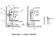
すなわち、実施例1の解除スイッチ34の機構では、解除スイッチ34を動作させるためにネジ37の先端を使用する機構としていたが、実施例2の解除スイッチ34では、図8に示したように、解除スイッチ34とネジ37の間に支点Bを回転支点として回動するレバー40を設け、さらにこのレバー40の回動に連動し、支点Cを回転支点として回動するリンク41を設け、保守の際に、ネジ37を取り外し解除スイッチ34をオフしたときに媒体収納装置20の扉24が閉まらなくなる構成としている。
That is, in the mechanism of the
(動作)
以上の構成により、実施例2の媒体収納装置は、以下のように動作する。なお、保守作業員が、防犯検出部50の保守として電池やインク等を交換する必要性については、実施例1と同様であるので、簡略化のためにその説明を省略する。
(Operation)
With the above configuration, the medium storage device according to the second embodiment operates as follows. Note that the necessity for the maintenance worker to replace the battery, ink, and the like for maintenance of the crime
図8は、前記解除スイッチ34の動作を説明する説明図である。解除スイッチ34は、例えばマイクロスイッチ等からなりカバー36の内部に設けられ、カバー36を取り付けるネジ37の先端がA方向に移動することにより、解除スイッチ34がオン/オフするようになっている。
FIG. 8 is an explanatory diagram for explaining the operation of the
そして、支点Bを回転支点として回動するレバー40の下端部にレバー40と連動して支点Cを回転支点として回動するリンク41が設けられ、レバー40が回動することにより媒体収納装置20の扉24側へのリンク41の突出量が変わるようになっている。
A
図8(a)は、カバー36がネジ37で取り付けられた防犯検出動作中の状態の図であり、ネジ37の先端によりレバー40が押されD方向に回動し解除スイッチ34がオン状態となるとともに、レバー40の下端部がレバー41に干渉しない方向に回動するので、リンク41がE方向に回動し当該左端が媒体収納装置20の扉24より内側となる。
FIG. 8A is a diagram showing a state in which the
一方、図8(b)は、ネジ37を外して保守を行うときの状態の図であり、ネジ37が外されると解除スイッチ34がオフ状態となるとともに、図示せぬスプリング等によりF方向に付勢されたレバー40が同図のように回動するので、これに連動してリンク41がG方向に回動し当該左端が扉24と干渉する位置となり、媒体収納装置20の扉24が閉まらない状態となる。
On the other hand, FIG. 8B is a diagram of a state when maintenance is performed with the
以上のように、防犯検出部50は、カバー36を取り付ける際には前記ネジ37が必要であり、保守のためにカバー36を外す際にはネジ37を必ず取り外さなければならない構成となっているので、保守作業員が、前述の電池31、警報出力部30等を交換する保守作業を行うとき、ネジ37を取り外してカバー36を外すと、解除スイッチ34がオフ状態となり、防犯検出部50の機能が無効化されるとともに、扉24も閉められなくなる。
As described above, the crime
そして、保守を終了し、前記ネジ37によりカバー36を取り付けると、解除スイッチ34がネジ37先端により押されオン状態となるので、防犯検出機能を有効とすることができるとともに、扉24を閉められるようになる。
When the maintenance is finished and the
なお、ネジ37は、所定の長さがないと解除スイッチ34を押し切れず防犯検出部35の機能が有効とならないこともあるので、特殊なネジ径、ピッチの構造とし、所定のネジ37でなければカバー36を取り付けられないようにして置くとよいことは実施例1と同様である。
If the
また、所定の長さがないネジによりカバー36を取り付けた場合であっても、レバー40はF方向に回動したままで、リンク41もG方向に回動したまま状態となり、扉24は閉められない状態となるので、通常の運用に移行することができない。このため、防犯検出部50の機能が無効化された状態で通常運用に移行することはない。
Even when the
以上の実施例の説明では、ネジ37を取り付けないと媒体収納装置20の扉24を閉じられない構成としてレバー40とリンク41を用いる構成を説明したが、ネジ37を取り付けることにより干渉部材が扉24より離れ、ネジ37を取り外すことにより扉24と干渉する位置に移動するような機構であればどのような構成であってもよい。例えばレバー40とリンク41を1つのレバーとし、当該レバーを扉側24にバネ等で付勢しておき、ネジ37を取り付けることにより扉24より離れ、ネジ37を取り外すことにより扉24と干渉する位置に移動するようにしてもよい。
In the above description of the embodiment, the configuration in which the
(実施例2の効果)
以上詳細に述べたように、実施例2の媒体収納装置によれば、保守作業員が防犯検出部50の機能を解除したまま保守作業を終了した場合、媒体収納装置の扉24が閉まらない構成としたので、実施例1の効果に加え、防犯検出部の機能を解除したまま、通常運用に移行することを確実に防止することができる。
(Effect of Example 2)
As described above in detail, according to the medium storage device of the second embodiment, when the maintenance worker finishes the maintenance work while releasing the function of the
《その他の変形例》
以上の実施例の説明では、解除スイッチ34としてマイクロスイッチ等のメカスイッチからなるように説明したが、ネジ37の先端、レバー40或いはリンク41の位置を光学センサなどを用いて検出するようにしても勿論よい。
<< Other modifications >>
In the above description of the embodiment, the
以上述べたように、本発明は、破壊や振動等を検出する媒体収納装置を備えた取引装置などに広く用いることができる。 As described above, the present invention can be widely used for transaction apparatuses equipped with a medium storage device that detects destruction, vibration, and the like.
20 媒体収納装置
24 扉
28 防犯センサ
30 警報出力部
31 電池
34 解除スイッチ
35 防犯検出制御部
36 カバー
37 ネジ
40 レバー
41 リンク
50 防犯検出部
20
Claims (2)
前記防犯検出部のカバーを取り付けるためのネジ部を設け、
該ネジ部にネジを取り付けることにより防犯検出部の機能を有効とするようにしたことを特徴とする媒体収納装置。 In the medium storage device having the security detection part,
Provide a screw part for attaching the cover of the security detection part,
A medium storage device characterized in that the function of the security detection unit is made effective by attaching a screw to the screw unit .
前記ネジの取り付けと連動する扉干渉部材を設け、Provide a door interference member that interlocks with the mounting of the screw,
前記ネジの取り付けにより前記扉干渉部材を前記扉を干渉しない位置に移動させ、前記ネジを取り外すことにより前記扉を干渉する位置に移動させるようにしたことを特徴とする請求項1記載の媒体収納装置。The medium storage according to claim 1, wherein the door interference member is moved to a position where the door is not interfered by attaching the screw, and the door is moved to a position where the door is interfered by removing the screw. apparatus.
Priority Applications (1)
| Application Number | Priority Date | Filing Date | Title |
|---|---|---|---|
| JP2005049421A JP4734958B2 (en) | 2005-02-24 | 2005-02-24 | Medium storage device |
Applications Claiming Priority (1)
| Application Number | Priority Date | Filing Date | Title |
|---|---|---|---|
| JP2005049421A JP4734958B2 (en) | 2005-02-24 | 2005-02-24 | Medium storage device |
Publications (3)
| Publication Number | Publication Date |
|---|---|
| JP2006235987A JP2006235987A (en) | 2006-09-07 |
| JP2006235987A5 JP2006235987A5 (en) | 2007-04-05 |
| JP4734958B2 true JP4734958B2 (en) | 2011-07-27 |
Family
ID=37043570
Family Applications (1)
| Application Number | Title | Priority Date | Filing Date |
|---|---|---|---|
| JP2005049421A Expired - Fee Related JP4734958B2 (en) | 2005-02-24 | 2005-02-24 | Medium storage device |
Country Status (1)
| Country | Link |
|---|---|
| JP (1) | JP4734958B2 (en) |
Citations (4)
| Publication number | Priority date | Publication date | Assignee | Title |
|---|---|---|---|---|
| JPH06229154A (en) * | 1993-01-29 | 1994-08-16 | Matsushita Electric Works Ltd | Wireless security system |
| JP2001175918A (en) * | 1999-12-14 | 2001-06-29 | Oki Joho Systems:Kk | Medium storage device |
| JP2003512662A (en) * | 1999-10-15 | 2003-04-02 | データ・アイ/オゥ・コーポレイション | Supply device / programming / buffer operation system |
| JP2003327367A (en) * | 2002-05-13 | 2003-11-19 | Hitachi Building Systems Co Ltd | Theft preventive device for elevator |
-
2005
- 2005-02-24 JP JP2005049421A patent/JP4734958B2/en not_active Expired - Fee Related
Patent Citations (4)
| Publication number | Priority date | Publication date | Assignee | Title |
|---|---|---|---|---|
| JPH06229154A (en) * | 1993-01-29 | 1994-08-16 | Matsushita Electric Works Ltd | Wireless security system |
| JP2003512662A (en) * | 1999-10-15 | 2003-04-02 | データ・アイ/オゥ・コーポレイション | Supply device / programming / buffer operation system |
| JP2001175918A (en) * | 1999-12-14 | 2001-06-29 | Oki Joho Systems:Kk | Medium storage device |
| JP2003327367A (en) * | 2002-05-13 | 2003-11-19 | Hitachi Building Systems Co Ltd | Theft preventive device for elevator |
Also Published As
| Publication number | Publication date |
|---|---|
| JP2006235987A (en) | 2006-09-07 |
Similar Documents
| Publication | Publication Date | Title |
|---|---|---|
| JP5928109B2 (en) | Cash processing device and unit lock mechanism used for the cash processing device | |
| JP4734958B2 (en) | Medium storage device | |
| KR101077320B1 (en) | Locking deive of A.T.M. | |
| JP4958629B2 (en) | Automatic transaction equipment | |
| JP5579522B2 (en) | Money handling apparatus and money handling system | |
| US8167135B2 (en) | Apparatus and method for accepting or dispensing bank notes | |
| JP2014119808A (en) | Currency processing system, money bar storage device and currency processing method | |
| KR100603936B1 (en) | Shutter device and method for operating the shutter device | |
| JP3838836B2 (en) | Medium storage device | |
| JP6060657B2 (en) | Cash machine | |
| JP5507650B2 (en) | Automatic transaction equipment | |
| JP2006099647A (en) | Automatic transaction apparatus | |
| JP2006252580A (en) | Banknote housing apparatus | |
| WO2020129382A1 (en) | Cash processing device | |
| JP5288253B2 (en) | Cash collection equipment | |
| JP5844417B2 (en) | Money handling apparatus and money handling system | |
| JP5367273B2 (en) | Bar metal storage | |
| JPH06162318A (en) | Paper money recognition device | |
| WO2016143220A1 (en) | Automatic transaction device | |
| JP4284035B2 (en) | Card issuing device | |
| JP7154893B2 (en) | automatic teller machine | |
| JP5227578B2 (en) | Automatic transaction equipment | |
| WO2016143222A1 (en) | Automatic transaction device | |
| JP6571829B2 (en) | Money handling system | |
| JP6329307B2 (en) | Money handling system and bar storage device |
Legal Events
| Date | Code | Title | Description |
|---|---|---|---|
| RD01 | Notification of change of attorney |
Free format text: JAPANESE INTERMEDIATE CODE: A7421 Effective date: 20060923 |
|
| RD02 | Notification of acceptance of power of attorney |
Free format text: JAPANESE INTERMEDIATE CODE: A7422 Effective date: 20060929 |
|
| RD04 | Notification of resignation of power of attorney |
Free format text: JAPANESE INTERMEDIATE CODE: A7424 Effective date: 20061013 |
|
| A521 | Written amendment |
Free format text: JAPANESE INTERMEDIATE CODE: A523 Effective date: 20070214 |
|
| A621 | Written request for application examination |
Free format text: JAPANESE INTERMEDIATE CODE: A621 Effective date: 20070214 |
|
| A621 | Written request for application examination |
Free format text: JAPANESE INTERMEDIATE CODE: A621 Effective date: 20070214 |
|
| A977 | Report on retrieval |
Free format text: JAPANESE INTERMEDIATE CODE: A971007 Effective date: 20100705 |
|
| A131 | Notification of reasons for refusal |
Free format text: JAPANESE INTERMEDIATE CODE: A131 Effective date: 20100713 |
|
| A521 | Written amendment |
Free format text: JAPANESE INTERMEDIATE CODE: A523 Effective date: 20100903 |
|
| TRDD | Decision of grant or rejection written | ||
| A01 | Written decision to grant a patent or to grant a registration (utility model) |
Free format text: JAPANESE INTERMEDIATE CODE: A01 Effective date: 20110329 |
|
| A61 | First payment of annual fees (during grant procedure) |
Free format text: JAPANESE INTERMEDIATE CODE: A61 Effective date: 20110411 |
|
| R150 | Certificate of patent or registration of utility model |
Ref document number: 4734958 Country of ref document: JP Free format text: JAPANESE INTERMEDIATE CODE: R150 Free format text: JAPANESE INTERMEDIATE CODE: R150 |
|
| FPAY | Renewal fee payment (event date is renewal date of database) |
Free format text: PAYMENT UNTIL: 20140513 Year of fee payment: 3 |
|
| FPAY | Renewal fee payment (event date is renewal date of database) |
Free format text: PAYMENT UNTIL: 20140513 Year of fee payment: 3 |
|
| S531 | Written request for registration of change of domicile |
Free format text: JAPANESE INTERMEDIATE CODE: R313531 |
|
| FPAY | Renewal fee payment (event date is renewal date of database) |
Free format text: PAYMENT UNTIL: 20140513 Year of fee payment: 3 |
|
| R350 | Written notification of registration of transfer |
Free format text: JAPANESE INTERMEDIATE CODE: R350 |
|
| LAPS | Cancellation because of no payment of annual fees |