JP4734026B2 - Electrolyzer - Google Patents

Electrolyzer Download PDF

Info

Publication number
JP4734026B2
JP4734026B2 JP2005141892A JP2005141892A JP4734026B2 JP 4734026 B2 JP4734026 B2 JP 4734026B2 JP 2005141892 A JP2005141892 A JP 2005141892A JP 2005141892 A JP2005141892 A JP 2005141892A JP 4734026 B2 JP4734026 B2 JP 4734026B2
Authority
JP
Japan
Prior art keywords
electrode
anode
cathode
electrolytic
fixed electrode
Prior art date
Legal status (The legal status is an assumption and is not a legal conclusion. Google has not performed a legal analysis and makes no representation as to the accuracy of the status listed.)
Expired - Lifetime
Application number
JP2005141892A
Other languages
Japanese (ja)
Other versions
JP2006314958A (en
Inventor
尋明 猪鹿倉
等 中村
真 佐藤
一博 宇都宮
Current Assignee (The listed assignees may be inaccurate. Google has not performed a legal analysis and makes no representation or warranty as to the accuracy of the list.)
Toshiba Corp
Original Assignee
Toshiba Corp
Priority date (The priority date is an assumption and is not a legal conclusion. Google has not performed a legal analysis and makes no representation as to the accuracy of the date listed.)
Filing date
Publication date
Application filed by Toshiba Corp filed Critical Toshiba Corp
Priority to JP2005141892A priority Critical patent/JP4734026B2/en
Publication of JP2006314958A publication Critical patent/JP2006314958A/en
Application granted granted Critical
Publication of JP4734026B2 publication Critical patent/JP4734026B2/en
Anticipated expiration legal-status Critical
Expired - Lifetime legal-status Critical Current

Links

Images

Classifications

    • YGENERAL TAGGING OF NEW TECHNOLOGICAL DEVELOPMENTS; GENERAL TAGGING OF CROSS-SECTIONAL TECHNOLOGIES SPANNING OVER SEVERAL SECTIONS OF THE IPC; TECHNICAL SUBJECTS COVERED BY FORMER USPC CROSS-REFERENCE ART COLLECTIONS [XRACs] AND DIGESTS
    • Y02TECHNOLOGIES OR APPLICATIONS FOR MITIGATION OR ADAPTATION AGAINST CLIMATE CHANGE
    • Y02EREDUCTION OF GREENHOUSE GAS [GHG] EMISSIONS, RELATED TO ENERGY GENERATION, TRANSMISSION OR DISTRIBUTION
    • Y02E30/00Energy generation of nuclear origin
    • Y02E30/30Nuclear fission reactors
    • YGENERAL TAGGING OF NEW TECHNOLOGICAL DEVELOPMENTS; GENERAL TAGGING OF CROSS-SECTIONAL TECHNOLOGIES SPANNING OVER SEVERAL SECTIONS OF THE IPC; TECHNICAL SUBJECTS COVERED BY FORMER USPC CROSS-REFERENCE ART COLLECTIONS [XRACs] AND DIGESTS
    • Y02TECHNOLOGIES OR APPLICATIONS FOR MITIGATION OR ADAPTATION AGAINST CLIMATE CHANGE
    • Y02WCLIMATE CHANGE MITIGATION TECHNOLOGIES RELATED TO WASTEWATER TREATMENT OR WASTE MANAGEMENT
    • Y02W30/00Technologies for solid waste management
    • Y02W30/50Reuse, recycling or recovery technologies

Landscapes

  • Electrolytic Production Of Non-Metals, Compounds, Apparatuses Therefor (AREA)

Description

本発明は、使用済燃料の再処理を行なう乾式再処理技術に係り、特に、使用済燃料の中から有効成分を電解により電極に析出させて回収する電解装置に関する。   The present invention relates to a dry reprocessing technique for reprocessing spent fuel, and more particularly to an electrolyzer that deposits and collects active components from spent fuel by electrolysis.

原子力発電所から発生する使用済燃料には、ウラン、プルトニウム、超ウラン元素(TRU元素)の酸化物の他に、核分裂生成物(FP)であるアルカリ金属、アルカリ土類金属などの酸化物が含まれている。   Spent fuel generated from nuclear power plants includes oxides of alkali metals and alkaline earth metals that are fission products (FP) in addition to oxides of uranium, plutonium, and transuranium elements (TRU elements). include.

使用済燃料は、燃料被覆管内にペレット状に充填されており、この使用済燃料の処理には、燃料被覆管の除去(脱被覆)および使用済酸化物燃料の粉砕が要求される。使用済燃料は、燃料被覆管の脱被覆および粉砕処理を行なった後、溶融塩中に加熱されて溶解し、得られた溶液を電解工程で電解し、この電解により電極(陰極)側に析出したウランやプルトニウムの顆粒状酸化物から顆粒燃料を得る処理を行なって、原子炉燃料として再利用に供するようになっている。   The spent fuel is filled in the form of pellets in the fuel cladding tube, and processing of this spent fuel requires removal of the fuel cladding tube (decovering) and pulverization of the spent oxide fuel. The spent fuel is decoated and pulverized in the fuel cladding tube, heated and dissolved in the molten salt, and the resulting solution is electrolyzed in an electrolysis process. This electrolysis deposits on the electrode (cathode) side. Granule fuel is obtained from the granular oxides of uranium and plutonium, and is used as nuclear reactor fuel for reuse.

溶解工程で溶解された使用済燃料を含む溶液を電解させる電解装置には、特許文献1に開示された技術がある。   As an electrolysis apparatus for electrolyzing a solution containing spent fuel dissolved in a dissolution process, there is a technique disclosed in Patent Document 1.

この電解装置は、るつぼ内に収納された溶融塩内に陽極とロッド状の陰極とを対向設置して浸漬させ、両電極間に電解用電源により電圧を印加させることで、電解処理を行なうようになっている。この電解装置は、るつぼ内の溶融塩に使用済燃料を脱被覆および粉砕処理物投入するため、上蓋に投入ホッパを設けたり、また、陽極をバスケット状に形成し、この陽極バスケットに使用済燃料の粉砕物を収納させている。   In this electrolysis apparatus, an anode and a rod-like cathode are placed oppositely in a molten salt housed in a crucible and immersed, and a voltage is applied between the electrodes by an electrolysis power source so as to perform an electrolytic treatment. It has become. In this electrolyzer, in order to put the spent fuel into the molten salt in the crucible and put the pulverized product, a charging hopper is provided on the upper lid, and the anode is formed in a basket shape, and the spent fuel is placed in the anode basket. Is stored.

この電解装置は、両電極間に電圧を印加させることで、溶融塩中に溶解して溶け込んだ溶液が、陰極上にUOやPuO等の顆粒状酸化物として析出される。 In this electrolysis apparatus, by applying a voltage between both electrodes, a solution dissolved in the molten salt is deposited as a granular oxide such as UO 2 or PuO 2 on the cathode.

電解析出物がUO等の導電性の大きな酸化物である場合には、剥ぎ取り機構を設けず、電解装置の上蓋を開放させて固体電極をるつぼ外に取り出し、固体電極に析出された電解析出物を回収している。 When the electrolytic deposit is a highly conductive oxide such as UO 2 , the stripping mechanism is not provided, the upper lid of the electrolysis apparatus is opened, the solid electrode is taken out of the crucible, and deposited on the solid electrode. Electrolytic deposits are collected.

また、電解析出物がPuO等の電気抵抗の大きな酸化物である場合には、剥ぎ取り機構を固定電極に装着した状態で電解処理を行ない、固定電極に析出した電解析出物を、剥ぎ取り機構の手動操作により掻き取っている。手動操作では、剥ぎ取り機構の剥ぎ取り刃を固体電極(陰極)に接触させて掻き取り、電極外周面から析出した電解析出物を剥ぎ取り、下方の受皿に回収している。
特開平9−90089号公報
Further, when the electrolytic deposit is an oxide having a large electrical resistance such as PuO 2 , the electrolytic treatment is performed with the stripping mechanism attached to the fixed electrode, and the electrolytic deposit deposited on the fixed electrode is It is scraped off by manual operation of the stripping mechanism. In the manual operation, the scraping blade of the stripping mechanism is brought into contact with the solid electrode (cathode) and scraped off, and the electrolytic deposit deposited from the outer peripheral surface of the electrode is stripped and collected in a lower tray.
Japanese Patent Laid-Open No. 9-90089

従来の乾式再処理技術に用いられる電解装置は、剥ぎ取り機構が固定電極に着脱自在に取り付けられ、剥ぎ取り機構に取り付けられた剥ぎ取り刃を固体電極外周面に接触させて電極外表面から電解析出物を掻き取るようになっている。   In the electrolysis apparatus used in the conventional dry reprocessing technology, the peeling mechanism is detachably attached to the fixed electrode, and the peeling blade attached to the peeling mechanism is brought into contact with the outer peripheral surface of the solid electrode so that the electric power is supplied from the outer surface of the electrode. The analysis product is scraped off.

従来の電解装置では、電解処理により陰極(固体電極)に析出された電解析出物を回収するために、電解装置の上蓋を取り外して固体電極をるつぼ外に取り出したり、また、電解装置の運用(運転)を停止させて剥ぎ取り機構を手動操作し、剥ぎ取り機構の剥ぎ取り刃を固体電極表面に接触させ、人為的操作により、電極表面から電解析出物を掻き取るようになっており、電解析出物を効率よく回収することができなかった。   In the conventional electrolyzer, in order to collect the electrolytic deposit deposited on the cathode (solid electrode) by the electrolysis treatment, the top electrode of the electrolyzer is removed and the solid electrode is taken out of the crucible. (Operation) is stopped, the stripping mechanism is manually operated, the stripping blade of the stripping mechanism is brought into contact with the surface of the solid electrode, and the electrolytic deposit is scraped off from the electrode surface by human operation. The electrolytic deposit could not be recovered efficiently.

従来の電解装置では、電解析出物を電極外表面から掻き取って回収する都度、電解装置の運転を中止させなければならず、電解装置を効率よく、能率的に運用させることが困難であった。   In the conventional electrolysis apparatus, every time the electrolytic deposit is scraped off and collected from the outer surface of the electrode, the operation of the electrolysis apparatus must be stopped, and it is difficult to operate the electrolysis apparatus efficiently and efficiently. It was.

また、電解析出物の析出状況によっては、固体電極に堆積していく析出物により電極間が短絡して、電解作用が不能になったり、電極間が短絡すると、充分な析出量を得る前に電解装置を停止させて回収作業を行なわなければならなかった。   In addition, depending on the deposition state of the electrolytic deposit, if the electrode is short-circuited by the deposit deposited on the solid electrode and the electrolytic action becomes impossible or the electrodes are short-circuited, a sufficient amount of deposition may not be obtained. It was necessary to stop the electrolyzer and perform the recovery work.

本発明は、上述した事情を考慮してなされたもので、運転を停止させることなく、電解処理を効率的に能率よく行なって電解析出物を回収することができる電解装置を提供することを目的とする。   The present invention has been made in consideration of the above-described circumstances, and provides an electrolytic apparatus that can efficiently perform electrolytic treatment efficiently and recover electrolytic deposits without stopping operation. Objective.

本発明の他の目的は、電解析出物を遠隔操作で回収可能にし、電極間の距離を常に(広く)確保し、最適な析出状態を保って電解装置を連続的にかつ効率的に運用することができる電解装置を提供することにある。   Another object of the present invention is to make it possible to collect electrolytic deposits by remote control, always ensure the distance between the electrodes (wide), and keep the optimal deposition state in order to operate the electrolyzer continuously and efficiently. It is an object of the present invention to provide an electrolyzer that can be used.

本発明に係る電解装置は、上述した課題を解決するために、請求項1に記載したように、溶融塩を収納するるつぼと、このるつぼを加熱する加熱手段と、前記るつぼ内に収容され、陽極と陰極とを有する電極装置と、この電極装置の両電極間に電源を供給する電解用電源回路と、前記電極装置の可動電極を昇降可能かつ回転可能に駆動する電極駆動装置と、前記両電極に電源を供給することにより、陰極側に析出する電解析出物を回収する回収装置とを有し、前記電極装置はるつぼ内の溶融塩に浸漬可能に設けられたトーラス状あるいは円環状の固定電極と、この固定電極の内側に出し入れ可能に配設される可動電極とを有し、前記両電極の一方を陽極に、その他方を陰極に構成し、前記電極装置の固定電極は陽極あるいは陰極に、可動電極は陰極あるいは陽極にそれぞれ形成され、前記可動電極は、前記電極駆動装置により固定電極から上方に後退した待機位置と、固定電極に対応する電解析出位置と、固定電極より下降した電解析出物の回収位置との間を選択的に移動せしめられるように構成されたものである。
また、本発明に係る電解装置は、上述した課題を解決するために、請求項5に記載したように、溶融塩を収納するるつぼと、このるつぼを加熱する加熱手段と、前記るつぼ内に収容され、陽極と陰極とを有する電極装置と、この電極装置の両電極間に電源を供給する電解用電源回路と、前記電極装置の可動電極を昇降可能かつ回転可能に駆動する電極駆動装置と、前記両電極に電源を供給することにより、陰極側に析出する電解析出物を回収する回収装置とを有し、前記電極装置はるつぼ内の溶融塩に浸漬可能に設けられたトーラス状あるいは円環状の固定電極と、この固定電極の内側に出し入れ可能に配設される可動電極とを有し、前記両電極の一方を陽極に、その他方を陰極に構成し、前記電極装置は、トーラス状あるいは円環状の固定電極と、この固定電極の内側に出し入れ可能な可動電極とを有し、前記固定電極は内周面が逆截頭円錐形状に形成され、この固定電極の内側に収納可能な可動電極は外周面が逆截頭円錐形状に形成され、両電極間に逆截頭円錐形状あるいはロート形状の電極間間隙が形成されたものである。
In order to solve the above-described problem, an electrolysis apparatus according to the present invention is housed in a crucible containing a molten salt, heating means for heating the crucible, and the crucible, as described in claim 1. An electrode device having an anode and a cathode; an electrolysis power supply circuit that supplies power between both electrodes of the electrode device; an electrode drive device that drives the movable electrode of the electrode device to be movable up and down; A recovery device that recovers electrolytic deposits deposited on the cathode side by supplying power to the electrode, and the electrode device is a torus-like or annular shape provided so as to be immersed in the molten salt in the crucible. A fixed electrode, and a movable electrode disposed inside and outside the fixed electrode, wherein one of the electrodes is an anode and the other is a cathode. The fixed electrode of the electrode device is an anode or Movable electrode on the cathode The movable electrode is formed on the cathode or the anode, respectively, and the movable electrode includes a standby position retracted upward from the fixed electrode by the electrode driving device, an electrolytic deposition position corresponding to the fixed electrode, and an electrolytic deposit lowered from the fixed electrode. It is configured to be selectively moved between the collection positions .
Moreover, in order to solve the above-described problem, an electrolytic apparatus according to the present invention contains a crucible for storing molten salt, a heating means for heating the crucible, and a crucible stored in the crucible. An electrode device having an anode and a cathode, an electrolysis power supply circuit for supplying power between both electrodes of the electrode device, an electrode driving device for driving the movable electrode of the electrode device to be movable up and down and rotatable, A recovery device for recovering electrolytic deposits deposited on the cathode side by supplying power to both electrodes, and the electrode device is a torus or circle provided so as to be immersed in the molten salt in the crucible. An annular fixed electrode and a movable electrode disposed inside and outside the fixed electrode are provided, and one of the electrodes is configured as an anode and the other is configured as a cathode. Or annular fixing And a movable electrode that can be taken in and out of the fixed electrode. The inner surface of the fixed electrode is formed in a reverse frustoconical shape, and the movable electrode that can be stored inside the fixed electrode is an outer peripheral surface. Is formed in a reverse frustoconical shape, and an interelectrode gap having a reverse frustoconical shape or funnel shape is formed between both electrodes.

本発明の電解装置は、陽極と陰極間の電極間間隙を保って電解析出・回収作業の連続運転が可能となり、陰極側に析出した電解析出物を効率よく回収させることができ、電解装置の運用効率の向上が図れ、UO等の電解析出物の回収量を増加させることができる。 The electrolysis apparatus of the present invention enables continuous operation of electrolytic deposition / recovery operation while maintaining a gap between the anode and the cathode, and can efficiently recover the electrolytic deposit deposited on the cathode side. The operational efficiency of the apparatus can be improved, and the amount of recovered electrolytic deposits such as UO 2 can be increased.

本発明に係る電解装置の実施形態について添付図面を参照して説明する。   An embodiment of an electrolysis apparatus according to the present invention will be described with reference to the accompanying drawings.

図1は本発明に係る電解装置の第1実施形態を概略的に示す全体構成図である。   FIG. 1 is an overall configuration diagram schematically showing a first embodiment of an electrolysis apparatus according to the present invention.

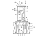
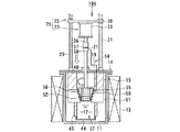
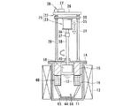
図1は、電解装置10の運用前の電極待機状態を示す縦断面図であり、図2は、電解装置10の電解処理による電解析出物の析出状態を示す断面図、図3は、電解装置10における電解析出物の回収状態を示す断面図である。   FIG. 1 is a longitudinal sectional view showing an electrode standby state before operation of the electrolysis apparatus 10, FIG. 2 is a cross-sectional view showing a deposition state of electrolytic deposits by electrolysis treatment of the electrolysis apparatus 10, and FIG. FIG. 3 is a cross-sectional view showing a state of collecting electrolytic deposits in the apparatus 10.

電解装置10は、原子力発電所から出る使用済燃料の溶解と電解を行なってUO,PuO等の顆粒状酸化物からなる電解析出物を析出させ、回収を行なう装置である。 The electrolyzer 10 is an apparatus for performing recovery by depositing electrolytic deposits made of granular oxides such as UO 2 and PuO 2 by dissolving and electrolyzing spent fuel from a nuclear power plant.

電解装置10は、磁製または金属製、例えばグラファイト製のるつぼ11を有し、このるつぼ11内に溶融状態の塩12が収容される。溶融塩12は、例えば塩化ナトリウム、塩化カリウムのようなアルカリ金属の塩化物で形成される。るつぼ11の外周側には加熱ヒータ13が加熱手段として設けられる。加熱ヒータ13は、るつぼ11の外周側に保護容器を介して設けてもよい。加熱ヒータ13は、るつぼ11を例えば500℃〜700℃の高温に加熱するようになっている。   The electrolyzer 10 has a crucible 11 made of magnetism or metal, for example, graphite, and a molten salt 12 is accommodated in the crucible 11. The molten salt 12 is formed of an alkali metal chloride such as sodium chloride or potassium chloride. On the outer peripheral side of the crucible 11, a heater 13 is provided as a heating means. The heater 13 may be provided on the outer peripheral side of the crucible 11 via a protective container. The heater 13 is configured to heat the crucible 11 to a high temperature of, for example, 500 ° C to 700 ° C.

るつぼ11の頂部は、上蓋14で覆われ、るつぼ11内が閉塞される。上蓋14には、筒状あるいはスリーブ状の断熱部材15を介して陽極バスケット16が設けられる。断熱部材15は筒状あるいは棒状をなし陽極バスケット16のサポートメンバとして機能する。   The top of the crucible 11 is covered with an upper lid 14 and the inside of the crucible 11 is closed. The upper lid 14 is provided with an anode basket 16 via a cylindrical or sleeve-like heat insulating member 15. The heat insulating member 15 has a cylindrical shape or a rod shape and functions as a support member of the anode basket 16.

陽極バスケット16は金網やパンチングメタル等のメッシュ部材あるいは開口部材を円筒状、スリーブ状あるいはトーラス状のバスケット形状に組み立てたものであり、るつぼ11内の外周側に一方の電極を陽極として構成している。この陽極バスケット16の内側に逆截頭円錐形状の可動電極17が他方の電極(陰極)として設けられる。両電極16,17により電極装置18が構成される。   The anode basket 16 is formed by assembling a mesh member or an opening member such as a wire mesh or punching metal into a cylindrical, sleeve-like or torus-like basket shape, and one electrode is configured as an anode on the outer peripheral side in the crucible 11. Yes. A movable electrode 17 having a reverse truncated cone shape is provided inside the anode basket 16 as the other electrode (cathode). An electrode device 18 is constituted by both electrodes 16 and 17.

陽極バスケット16は、るつぼ11内の周方向に沿って設けられたトーラス状あるいは円環状、円筒状の固定電極であり、バスケット内部に被覆管付使用済切断燃料(図示せず)が収納される。他方の電極17は、固定電極16の内側に同心円状に配置可能な可動電極を構成している。   The anode basket 16 is a torus-shaped, annular, or cylindrical fixed electrode provided along the circumferential direction in the crucible 11, and used cutting fuel with a cladding tube (not shown) is stored inside the basket. . The other electrode 17 constitutes a movable electrode that can be arranged concentrically inside the fixed electrode 16.

両電極16,17には電解用電源19により電解用電源回路20を介して電圧が印加され、一方の固定電極16は陽極として、他方の可動電極17は陰極として構成され、機能する。陰極17はスリップリング21を介して電解用電源19に接続される。   A voltage is applied to both the electrodes 16 and 17 by an electrolysis power source 19 via an electrolysis power supply circuit 20, and one fixed electrode 16 is configured as an anode and the other movable electrode 17 is configured as a cathode and functions. The cathode 17 is connected to an electrolysis power source 19 via a slip ring 21.

また、るつぼ11の上蓋14には電極昇降機構22と電極回転機構23を備えた電極駆動装置25が設けられ、この電極駆動装置25により可動電極17の昇降と回転(旋回撹拌)操作が遠隔制御可能に構成されている。   Further, the upper lid 14 of the crucible 11 is provided with an electrode driving device 25 having an electrode lifting mechanism 22 and an electrode rotating mechanism 23, and the electrode driving device 25 remotely controls the raising and lowering and rotating (swirl stirring) operation of the movable electrode 17. It is configured to be possible.

電極昇降機構22は、設置台26上に設けられた昇降モータ27と、この昇降モータ27のモータ駆動力が減速機構等の動力伝達手段28を介して伝達されるボールねじ等のスクリュシャフト29と、このスクリュシャフト29にねじ結合あるいはボールねじ結合された昇降ベース30と、昇降ベース30の昇降を、ベース回転不能に案内するガイドポール31とを備える。スクリュシャフト29およびガイドポール31はるつぼ11の上蓋14上に植設され、立設される。   The electrode elevating mechanism 22 includes an elevating motor 27 provided on an installation base 26, a screw shaft 29 such as a ball screw to which the motor driving force of the elevating motor 27 is transmitted through power transmission means 28 such as a speed reducing mechanism, and the like. The elevating base 30 is screwed or ball screwed to the screw shaft 29, and the guide pole 31 guides the elevating of the elevating base 30 so that the base cannot be rotated. The screw shaft 29 and the guide pole 31 are implanted on the upper lid 14 of the crucible 11 and are erected.

また、電極回転機構23は昇降ベース30に設けられた撹拌モータ35と、この撹拌モータ35のモータ駆動軸36にカップリング37を介して連結された回転ドライブ軸38とを有する。回転ドライブ軸38はるつぼ11の上蓋14に形成された軸受ボス40を貫いてるつぼ11内に入り、その先端に陰極としての可動電極17を設けている。可動電極17の外周面は下方に向って先細り構造の逆截頭円錐形状に形成される。   The electrode rotation mechanism 23 includes a stirring motor 35 provided on the elevating base 30, and a rotary drive shaft 38 connected to a motor drive shaft 36 of the stirring motor 35 via a coupling 37. The rotary drive shaft 38 passes through a bearing boss 40 formed on the upper lid 14 of the crucible 11 and enters the crucible 11, and a movable electrode 17 as a cathode is provided at the tip thereof. The outer peripheral surface of the movable electrode 17 is formed in an inverted frustoconical shape having a tapered structure facing downward.

さらに、るつぼ11内に設けられる陽極バスケット16の底部からサポート部材43が下方に延設され、このサポート部材43の先端に析出物の回収容器44が設けられる。サポート部材43はスリーブ状あるいは筒状メンバであっても、またロッド状メンバを複数本周方向に配設したものでもよい。サポート部材43には、析出物の掻き取り用カッタ45が取り付けられる。   Further, a support member 43 extends downward from the bottom of the anode basket 16 provided in the crucible 11, and a deposit collection container 44 is provided at the tip of the support member 43. The support member 43 may be a sleeve-shaped or cylindrical member, or a plurality of rod-shaped members arranged in the circumferential direction. A precipitate scraping cutter 45 is attached to the support member 43.

析出物の掻き取り用カッタ45は陽極バスケット16の下方で1本あるいは複数本、例えば2本が直径方向に対向して設けられる。析出物の掻き取り用カッタ45はカッタ刃が好ましくは平面視で直径方向に対向するように放射状に設けられ、各カッタ45のカッタ刃が回転電極17の逆截頭円錐面に沿うように下方に向って漸次接近する方向にテーパしている。   One or a plurality of, for example, two, scraper scraping cutters 45 are provided below the anode basket 16 in the diametrical direction. The cutter scraping cutters 45 are provided so that the cutter blades are preferably diametrically opposed in a plan view, and the cutter blades of the cutters 45 are positioned downward along the reverse truncated conical surface of the rotary electrode 17. Taper in the direction of gradually approaching toward.

析出物の掻き取り用カッタ45は、カッタ刃が下方に向って漸次互いに接近するテーパ形状に、かつ可動電極17の回転方向にヘリカル状あるいはラジカル状に形成してもよい。掻き取り用カッタ45の下方中央に析出物の受皿としての回収容器44が設置され、この回収容器44はサポート部材43の下端開口を覆うように設けられる。   The precipitate scraping cutter 45 may be formed in a tapered shape in which the cutter blades gradually approach each other downward, and in a helical shape or a radical shape in the rotational direction of the movable electrode 17. A collection container 44 as a deposit receiving tray is installed at the lower center of the scraping cutter 45, and the collection container 44 is provided so as to cover the lower end opening of the support member 43.

この電解装置10は電極駆動装置25の電極昇降機構22により、回転電極17が図1に示す待機位置と、図2に示す電解析出物位置と、図3に示す析出物回収装置とを選択的にとるように昇降自在に設けられる。   In the electrolyzer 10, the electrode lifting mechanism 22 of the electrode driving device 25 selects the standby position shown in FIG. 1, the electrolytic deposit position shown in FIG. 2, and the precipitate collection device shown in FIG. It can be moved up and down so that it can be taken.

また、電解装置10のるつぼ11内に溶融塩13が収納され、上蓋14で密閉される一方、この上蓋14には、るつぼ11内に反応ガスを吹き込むためのガス吹込管と、るつぼ11内からガスを排出するためのガス排出管(共に図示せず)が設けられる。反応ガスには塩素ガス、あるいは塩素と酸素の混合ガスのような酸化ガスが用いられる。   In addition, the molten salt 13 is housed in the crucible 11 of the electrolysis apparatus 10 and sealed with the upper lid 14, while the upper lid 14 has a gas blowing pipe for blowing reaction gas into the crucible 11 and the crucible 11 from the inside. A gas exhaust pipe (both not shown) for exhausting gas is provided. As the reaction gas, an oxidizing gas such as chlorine gas or a mixed gas of chlorine and oxygen is used.

さらに、陽極バスケット15内に使用済燃料(図示せず)が収納される。使用済燃料は、被覆管付燃料棒を軸方向に所要間隔をおいて切断した被覆管付切断燃料であり、この被覆管付切断燃料は陽極バスケット16内に燃料切断面が可動電極17側を向くように放射状に収容される。   Further, spent fuel (not shown) is stored in the anode basket 15. The spent fuel is a cut fuel with a cladding tube obtained by cutting a fuel rod with a cladding tube at a required interval in the axial direction, and this fuel with a cladding tube has a fuel cut surface on the side of the movable electrode 17 in the anode basket 16. It is accommodated radially so that it faces.

次に電解装置10の作用を説明する。   Next, the operation of the electrolysis apparatus 10 will be described.

電解装置10の運用(運転)前には、加熱ヒータ13に通電することでるつぼ11内が加熱される。この加熱ヒータ13への通電により、るつぼ11内に収容されたアルカリ金属の塩化物は加熱・溶融され、500℃〜700℃程度の高温・液状の溶融塩12となる。   Before operation (operation) of the electrolyzer 10, the inside of the crucible 11 is heated by energizing the heater 13. By energizing the heater 13, the alkali metal chloride contained in the crucible 11 is heated and melted to become a high-temperature / liquid molten salt 12 of about 500 ° C. to 700 ° C.

るつぼ11内を高温・液状の溶融塩12状態に保たれている間に、陽極バスケット16内に被覆管付切断燃料を収納させて、被覆管付切断燃料を収納した陽極バスケット16を、図1に示すように所定位置にセットする。   While the crucible 11 is kept in the high-temperature / liquid molten salt 12 state, the anode basket 16 containing the cutting fuel with the cladding tube is accommodated in the anode basket 16, and the anode basket 16 containing the cutting fuel with the cladding tube is stored in FIG. As shown in FIG.

その際、昇降ベース30が回転せず、昇降動作だけを行なうように、ガイドポール31にて案内され、昇降ベース30の回転方向の動きを拘束している。   At that time, the elevating base 30 is guided by the guide pole 31 so as to perform only the elevating operation without rotating, and the movement of the elevating base 30 in the rotational direction is restricted.

電解装置10の運用開始前に、図1に示すように待機位置にセットした状態で電極駆動装置25の電極昇降機構22を駆動させ、昇降ベース30を待機位置から下降させる。昇降ベース30の下降とともに電極回転機構23を駆動させ、撹拌モータ35を回転駆動させる。この撹拌モータ35の回転駆動により、カップリング37を介して回転ドライブ軸38も回転し、この回転軸38下端に固定された陰極17もるつぼ11内で回転され、陰極17は回転しながら下降する。   Prior to the start of operation of the electrolyzer 10, the electrode lifting mechanism 22 of the electrode driving device 25 is driven in a state of being set at the standby position as shown in FIG. 1, and the lift base 30 is lowered from the standby position. As the elevating base 30 is lowered, the electrode rotation mechanism 23 is driven, and the stirring motor 35 is rotated. Due to the rotational drive of the stirring motor 35, the rotary drive shaft 38 is also rotated through the coupling 37, the cathode 17 fixed to the lower end of the rotary shaft 38 is also rotated in the crucible 11, and the cathode 17 descends while rotating. .

その際、昇降ベース30は回転しないで昇降動作だけを行なうように、ガイドポール31にて案内され、昇降ベース30の回転方向の動きを拘束している。昇降ベース30の下降により、陰極(可動電極、回転電極)17は、陽極である固定電極16内に挿入され、固定電極16に対応する位置で下降が停止され、図2に示すように、陰極17は電解析出位置に持ち来される。可動電極(陰極)17が電解析出位置をとるとき、電極装置18の両電極16,17は平面視同心円状に配設され、電極間間隙(距離)が逆截頭円錐形状またはロート形状に維持される。   At that time, the elevating base 30 is guided by the guide pole 31 so as to perform only the elevating operation without rotating, and restrains the movement of the elevating base 30 in the rotational direction. As the elevating base 30 is lowered, the cathode (movable electrode, rotating electrode) 17 is inserted into the fixed electrode 16 serving as the anode, and the descent is stopped at a position corresponding to the fixed electrode 16, and as shown in FIG. 17 is brought to the electrolytic deposition position. When the movable electrode (cathode) 17 takes an electrolytic deposition position, both electrodes 16 and 17 of the electrode device 18 are arranged concentrically in a plan view, and the gap (distance) between the electrodes has a reverse frustoconical shape or a funnel shape. Maintained.

また、るつぼ11内の溶融塩12中には、ガス吹込管を通して酸化ガスである反応ガスが吹き込まれる一方、るつぼ11内のガスはガス排出管により排出され、外部にパージされる。   In addition, a reaction gas, which is an oxidizing gas, is blown into the molten salt 12 in the crucible 11 through a gas blowing pipe, while the gas in the crucible 11 is discharged through a gas discharge pipe and purged to the outside.

電極回転機構23の駆動により、陽極17は回転状態にキープされ、引き続き回転が保たれた状態で電解用電源回路20により電極装置18に通電され、陽極16と陰極17との間に電圧が印加される。この通電により、陽極バスケット16内の被覆管付切断燃料は溶融塩12内に溶解していき溶融する。溶融塩12に溶解した溶液は、陽極16と陰極17間への電圧印加により、時間の経過に伴って陰極にウランやプルトニウム等の顆粒状の酸化物が電解析出物50として生じ始める。電解析出物50の成長により陰極17側の径が増加していき、陰極17と陽極16との間の間隙が次第に小さくなっていく。   By driving the electrode rotating mechanism 23, the anode 17 is kept in a rotating state, and the electrode device 18 is energized by the electrolysis power supply circuit 20 while maintaining the rotation, and a voltage is applied between the anode 16 and the cathode 17. Is done. By this energization, the cut fuel with the cladding tube in the anode basket 16 is dissolved in the molten salt 12 and melted. The solution dissolved in the molten salt 12 starts to form granular oxides such as uranium and plutonium as electrolytic deposits 50 on the cathode as time passes by applying a voltage between the anode 16 and the cathode 17. The growth of the electrolytic deposit 50 increases the diameter on the cathode 17 side, and the gap between the cathode 17 and the anode 16 gradually decreases.

その際、陽極バスケット16内に収容された被覆管付切断燃料は、切断面が陰極17側を向くようにセットされ、陰極17側を向く被覆管付切断燃料の切断面積を大きく取ることができ、溶融塩への切断燃料の溶融効率を向上させることができる。   At that time, the cutting fuel with a cladding tube accommodated in the anode basket 16 is set so that the cutting surface faces the cathode 17 side, and the cutting area of the cutting fuel with a cladding tube facing the cathode 17 side can be increased. The melting efficiency of the cutting fuel into the molten salt can be improved.

この電解装置10は両電極16,17間への通電により、時間経過に伴って電解析出物50が陰極17側に生じ始め、電解析出物50の成長により陽極16側と接触が生じ始めたり、生じる前に、陰極17を回転させた状態で電極昇降機構22を駆動させて陰極17を下降させ、陰極17を図3に示す電解析出物50の回収位置に移動させる。   In the electrolysis apparatus 10, the electrolytic precipitate 50 starts to be generated on the cathode 17 side with the passage of time between the electrodes 16 and 17, and contact with the anode 16 side starts to be generated by the growth of the electrolytic precipitate 50. In the state where the cathode 17 is rotated, the electrode lifting mechanism 22 is driven to lower the cathode 17 to move the cathode 17 to the electrolytic deposit 50 collection position shown in FIG.

陰極17に析出した電解析出物50は、可動電極である陰極17が回転しながら電極昇降機構22の駆動により下降することにより、析出物の掻き取り用カッタ45に接触して徐々に掻き落とされることになり、最終的には、陰極17の電解析出物50は完全に除去される。   The electrolytic deposit 50 deposited on the cathode 17 descends by the driving of the electrode lifting mechanism 22 while the cathode 17 which is a movable electrode rotates, so that the electrolytic deposit 50 is gradually scraped off by contacting the deposit scraping cutter 45. Eventually, the electrolytic deposit 50 on the cathode 17 is completely removed.

掻き取り用カッタ45で掻き取られた電解析出物50は回収装置47の回収容器46に落下され、回収容器46内に回収されて堆積される。   The electrolytic deposit 50 scraped off by the scraping cutter 45 is dropped into the recovery container 46 of the recovery device 47 and recovered and deposited in the recovery container 46.

陰極17の電解析出物50が完全に除去されると、電極昇降機構22を駆動させて陰極17を引き上げ、陽極(陽極バスケット)16に対応する電解析出位置まで上昇して停止させ、再び電解処理を行なう。陰極17への電解析出物の析出状況に応じて一連の電解析出・回収作業を繰り返す。   When the electrolytic deposit 50 on the cathode 17 is completely removed, the electrode lifting mechanism 22 is driven to pull up the cathode 17, rise to an electrolytic deposition position corresponding to the anode (anode basket) 16, stop, and again Electrolytic treatment is performed. A series of electrolytic deposition / recovery operations are repeated according to the deposition state of the electrolytic deposit on the cathode 17.

一方、析出物の回収容器46内にはUO等顆粒状酸化物の電解析出物50が蓄積されていく。被覆管付使用済燃料(切断燃料)のウラン等の有効成分が無くなったら、るつぼ11の上蓋14を開けて、るつぼ11内機器を外に取り出し、回収装置47の回収容器46内の電解析出物50を取り出して回収し、回収作業が終了する。電解装置10は次の被覆管付使用済燃料の電解析出、回収作業に備えられる。 On the other hand, the electrolytic deposit 50 of granular oxide such as UO 2 is accumulated in the deposit collection container 46. When the active component such as uranium of the spent fuel with a cladding tube (cutting fuel) disappears, the upper cover 14 of the crucible 11 is opened, the equipment inside the crucible 11 is taken out, and the electrolytic deposition in the collection container 46 of the collection device 47 is taken out. The object 50 is taken out and collected, and the collection operation is completed. The electrolyzer 10 is prepared for the following electrolytic deposition and recovery of spent fuel with a cladding tube.

この実施形態の電解装置によれば、使用済燃料の被覆管付切断燃料に含まれる有効成分を、電解装置10の運転を停止させることなく、連続運転させて効率よく電解析出物として陰極17側に析出され、陰極17側に析出した電解析出物を回収装置47によりスムーズに能率的に回収させることができる。   According to the electrolysis apparatus of this embodiment, the active ingredient contained in the cut fuel with the cladding tube of the spent fuel is continuously operated without stopping the operation of the electrolysis apparatus 10 and efficiently used as the electrolytic deposit as the cathode 17. The electrolytic deposits deposited on the side and deposited on the cathode 17 side can be smoothly and efficiently collected by the collection device 47.

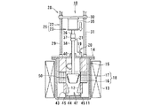
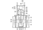
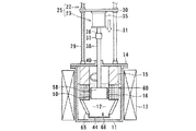
図4ないし図6は、本発明に係る電解装置の第2実施形態を示すものである。   4 to 6 show a second embodiment of the electrolysis apparatus according to the present invention.

図4は、電解装置10Aの運用前の電極待機状態を示す断面図であり、図5は電解装置10Aの運用状態を示すもので陰極側に析出される電解析出物50の析出状態を示す断面図、図6は電解装置10Aで析出された電解析出物50の回収状態を示す断面図である。   FIG. 4 is a cross-sectional view showing the electrode standby state before the operation of the electrolyzer 10A, and FIG. 5 shows the operation state of the electrolyzer 10A and shows the deposited state of the electrolytic deposit 50 deposited on the cathode side. FIG. 6 is a cross-sectional view showing a state in which the electrolytic deposit 50 deposited by the electrolytic apparatus 10A is recovered.

第2実施形態に示された電解装置10Aはるつぼ11内にトーラス状、リング状あるいは円筒状の固定電極51が陰極として収容され、この固定電極51の内側に可動電極52が陽極として出し入れ可能に設けられる。可動電極52は、電極駆動装置25の電極昇降機構22により昇降自在に、かつ電極回転機構23により回転自在に設けられる。   In the electrolysis apparatus 10A shown in the second embodiment, a torus-shaped, ring-shaped or cylindrical fixed electrode 51 is accommodated in a crucible 11 as a cathode, and a movable electrode 52 can be taken in and out of the fixed electrode 51 as an anode. Provided. The movable electrode 52 is provided so as to be movable up and down by the electrode lifting mechanism 22 of the electrode driving device 25 and rotatable by the electrode rotating mechanism 23.

固定電極51と可動電極52との間に電解用電源回路54により電源が供給され、電圧が印加される。電解用電源回路54から供給される電源は、固定電極51側が陰極に、可動電極52側が陽極となるようにプラス極とマイナス極が第1実施形態に示すものと反対になるように形成される。この固定電極52と可動電極53とにより電極装置55が構成される。   Power is supplied by the electrolysis power supply circuit 54 between the fixed electrode 51 and the movable electrode 52, and a voltage is applied. The power supplied from the electrolysis power circuit 54 is formed so that the positive electrode and the negative electrode are opposite to those shown in the first embodiment so that the fixed electrode 51 side is a cathode and the movable electrode 52 side is an anode. . The fixed electrode 52 and the movable electrode 53 constitute an electrode device 55.

電解装置10Aの他の構成および作用は、第1実施形態に示された電解装置10の構成および作用と実質的に異ならないので、共通する部分には同じ符号を付して簡略的に説明する。   Other configurations and operations of the electrolyzer 10A are not substantially different from the configurations and operations of the electrolyzer 10 shown in the first embodiment. Therefore, common portions are denoted by the same reference numerals and will be briefly described. .

図4に示された電解装置10Aは、るつぼ11の外側に加熱ヒータ13が設置されており、るつぼ11の中には溶融塩12が満たされている。るつぼ11の上部開口部は上蓋14で覆われており、この上蓋14に電極駆動装置25が設けられる。電極駆動装置25は、第1実施形態に示される電極駆動装置と同様、電極昇降機構22と電極回転機構23とから構成される。   In the electrolyzer 10 </ b> A shown in FIG. 4, a heater 13 is installed outside the crucible 11, and the crucible 11 is filled with a molten salt 12. The upper opening of the crucible 11 is covered with an upper lid 14, and an electrode driving device 25 is provided on the upper lid 14. The electrode driving device 25 includes an electrode lifting mechanism 22 and an electrode rotating mechanism 23 as in the electrode driving device shown in the first embodiment.

電極昇降機構22は、設置台26上に設けられた昇降モータ27とこのモータ回転軸に動力伝達機構28を介して連結されたスクリュシャフト29とが設けられ、このスクリュシャフト29に昇降ベース30が接続される。スクリュシャフト29の回転による昇降ベース30の昇降はガイドポール31により案内される。   The electrode elevating mechanism 22 is provided with an elevating motor 27 provided on an installation base 26 and a screw shaft 29 connected to the motor rotating shaft via a power transmission mechanism 28, and an elevating base 30 is provided on the screw shaft 29. Connected. The raising / lowering of the raising / lowering base 30 by rotation of the screw shaft 29 is guided by the guide pole 31.

また、昇降ベース30の中央部に電極回転機構23が設けられる。電極回転機構23は昇降ベース30の中央部下面あるいは上面に設置された撹拌モータ35を有し、この撹拌モータ35のモータ出力軸36はカップリング37を介して回転ドライブ軸38に連結される。この回転ドライブ軸38は上蓋14の中央部に形成される軸受ボス40を貫いてるつぼ11内に入り、その先端に可動電極52を設けている。   In addition, an electrode rotation mechanism 23 is provided at the center of the lift base 30. The electrode rotation mechanism 23 has a stirring motor 35 installed on the lower surface or the upper surface of the central portion of the elevating base 30, and the motor output shaft 36 of the stirring motor 35 is connected to a rotary drive shaft 38 via a coupling 37. The rotary drive shaft 38 passes through a bearing boss 40 formed at the center of the upper lid 14 and enters the crucible 11, and a movable electrode 52 is provided at the tip thereof.

また、回転ドライブ軸38の途中に電解用電源回路54を構成するスリップリング20が設けられ、可動電極52に電源をスムーズに供給できるようになっている。   Further, the slip ring 20 constituting the electrolysis power supply circuit 54 is provided in the middle of the rotary drive shaft 38 so that the power can be smoothly supplied to the movable electrode 52.

電極回転機構23の回転ドライブ軸38の下端に固定される可動電極52は、メッシュ状の金網あるいはパンチングプレートを外周側に設けた筒状あるいはスリーブ状のバスケットが設置される。可動電極52は陽極バスケットとして陽極を構成しており、この陽極バスケット52内に使用済燃料である被覆管付切断燃料が収容される。陽極バスケット52内に収容される使用済燃料は、燃料被覆管を除去し、燃料棒を所要間隔に切断したものであっても、裁断した破砕状のものであってもよい。   The movable electrode 52 fixed to the lower end of the rotary drive shaft 38 of the electrode rotating mechanism 23 is provided with a cylindrical or sleeve-like basket having a mesh-like wire net or a punching plate provided on the outer peripheral side. The movable electrode 52 constitutes an anode as an anode basket, and a cutting fuel with a cladding tube, which is a spent fuel, is accommodated in the anode basket 52. The spent fuel accommodated in the anode basket 52 may be one obtained by removing the fuel cladding tube and cutting the fuel rods at a required interval, or may be a crushed pulverized one.

陽極バスケット52の外周面には、電解析出物の掻き取り用カッタ56が設けられる。この掻き取り用カッタ56は陽極バスケット52の外周側に1箇所以上、好ましくは両サイド2箇所に設置される。掻き取り用カッタ56のカッタ刃は、下方に向って陽極バスケット52の外表面側に後退するようにテーパ形状に、また、陽極バスケット52の外周にヘリカル状あるいは螺旋状に設けられる。   An electrolytic deposit scraping cutter 56 is provided on the outer peripheral surface of the anode basket 52. The scraping cutter 56 is installed at one or more locations on the outer peripheral side of the anode basket 52, preferably at two locations on both sides. The cutter blade of the scraping cutter 56 is provided in a tapered shape so as to recede downward toward the outer surface side of the anode basket 52, and in a helical shape or a spiral shape on the outer periphery of the anode basket 52.

一方の陽極52に対向する他方の陰極51は、るつぼ11の溶融塩12内に浸漬され、トーラス状あるいは円環状に構成された固定電極である。固定電極51の中央部に形成される内周面は逆截頭円錐形状に形成され、陽極バスケット52に設けられた掻き取り用カッタ56に対向している。固定電極51の上部には支持部材としてのスリーブ状、筒状あるいはロッド状の断熱部材15が、また下部にはスリーブ状あるいは筒状サポート部材を介して析出物の回収容器44が設置される。   The other cathode 51 facing one anode 52 is a fixed electrode that is immersed in the molten salt 12 of the crucible 11 and configured in a torus shape or an annular shape. The inner peripheral surface formed in the central portion of the fixed electrode 51 is formed in a reverse truncated cone shape and faces a scraping cutter 56 provided in the anode basket 52. A sleeve-like, cylindrical or rod-like heat insulating member 15 as a support member is installed above the fixed electrode 51, and a precipitate collection container 44 is installed below the sleeve via a sleeve-like or cylindrical support member.

次に、電解装置10Aの作用を説明する。   Next, the operation of the electrolyzer 10A will be described.

電解装置10Aの運用前は、図4に示すようにセットされ、加熱ヒータ13に通電することで、るつぼ11内は加熱され、収容されたナトリウム塩化物等からなる溶融塩12は高温・液状となる。   Prior to the operation of the electrolyzer 10A, the crucible 11 is heated by energizing the heater 13 by being set as shown in FIG. 4, and the molten salt 12 made of sodium chloride or the like contained therein is in a high temperature / liquid state. Become.

また、電極回転機構23の回転ドライブ軸38の下端に設けられた可動電極(陽極)52は陽極バスケットで構成しており、この陽極バスケット52内に使用済燃料、例えば被覆管付切断燃料が収容されている。   The movable electrode (anode) 52 provided at the lower end of the rotary drive shaft 38 of the electrode rotating mechanism 23 is constituted by an anode basket, and spent fuel, for example, cutting fuel with a cladding tube is accommodated in the anode basket 52. Has been.

続いて、電極駆動装置25の電極昇降機構22および電極回転機構23が駆動され、電極昇降機構22のスクリュシャフト29にねじ結合あるいはボールねじ結合された昇降ベース30がガイドポール31に案内されて下動する。昇降ベース30は、昇降モータ27のモータ駆動に応じて回転せず、上下の昇降動作だけを行なうようにガイドポール31にて、その回転方向の動きを拘束している。   Subsequently, the electrode elevating mechanism 22 and the electrode rotating mechanism 23 of the electrode driving device 25 are driven, and the elevating base 30 screwed or ball screwed to the screw shaft 29 of the electrode elevating mechanism 22 is guided to the guide pole 31 and lowered. Move. The elevating base 30 is not rotated in accordance with the motor drive of the elevating motor 27, but the movement in the rotation direction is restricted by the guide pole 31 so as to perform only the up and down elevating operation.

電極昇降機構22の昇降ベース30の昇降とともに、電極回転機構23の撹拌モータ35を駆動させると、そのモータ駆動力で回転ドライブ軸38が回転し、陽極としての可動電極52は回転しながら下降する。可動電極52は、筒状の陽極バスケットとなっており、内部に使用済燃料としての被覆管付切断燃料が装荷されている。可動電極52は固定電極51の中央開口部内に回転しながら下降して、固定電極51に対応する位置、すなわち図5に示される電極析出位置に持ち来されてセットされる。   When the agitation motor 35 of the electrode rotation mechanism 23 is driven as the elevating base 30 of the electrode elevating mechanism 22 is raised and lowered, the rotary drive shaft 38 is rotated by the motor driving force, and the movable electrode 52 as the anode is lowered while rotating. . The movable electrode 52 is a cylindrical anode basket, and a cutting fuel with a cladding tube as a spent fuel is loaded therein. The movable electrode 52 descends while rotating into the central opening of the fixed electrode 51, and is brought to the position corresponding to the fixed electrode 51, that is, the electrode deposition position shown in FIG.

陽極52である陽極バスケットを電極回転機構23で回転させたまま、電解用電源回路54により電極装置55を構成する陽極52と陰極51との間に通電し、所要電圧を印加させる。両電極51,52間に電圧を印加させると、時間の経過に伴って陰極51にウラン酸化物等の電解析出物50が生じ始め、この電解析出物50は次第に成長していき、陽極52側と接触が生じるようになり、短絡が起き始める。   While the anode basket which is the anode 52 is rotated by the electrode rotating mechanism 23, the electrolysis power supply circuit 54 energizes between the anode 52 and the cathode 51 constituting the electrode device 55 to apply a required voltage. When a voltage is applied between the electrodes 51 and 52, an electrolytic deposit 50 such as uranium oxide begins to be formed on the cathode 51 with the passage of time, and this electrolytic deposit 50 grows gradually, 52 side comes into contact and a short circuit begins to occur.

陰極51に析出した電解析出物50により陽極52側と短絡が生じ始めると、電極昇降機構22を駆動させて電極52を図5に示す電解析出位置から図6に示す電解析出物の回収位置に電極52を回転させながら下降させる。   When short circuit with the anode 52 side starts to occur due to the electrolytic deposit 50 deposited on the cathode 51, the electrode lifting mechanism 22 is driven to move the electrode 52 from the electrolytic deposition position shown in FIG. 5 to the electrolytic deposit shown in FIG. The electrode 52 is lowered to the collection position while rotating.

陽極52である可動電極が電極駆動装置(電極昇降機構22と電極回転機構23)25の駆動により、回転しながら下降すると、陰極である固定電極25の内周面に析出された電解析出物50が徐々に掻き取り用カッタ56により掻き取られる。可動電極52が図6に示す析出物の回収位置まで下降すると、電極昇降機構22の駆動が停止され、それ以上の下降が停止せしめられる。   When the movable electrode which is the anode 52 is lowered while being rotated by the drive of the electrode driving device (electrode lifting mechanism 22 and electrode rotating mechanism 23) 25, the electrolytic deposit deposited on the inner peripheral surface of the fixed electrode 25 which is the cathode. 50 is gradually scraped off by the scraping cutter 56. When the movable electrode 52 is lowered to the deposit collection position shown in FIG. 6, the driving of the electrode lifting mechanism 22 is stopped, and further lowering is stopped.

可動電極52が回転しながら下降することにより、掻き取り用カッタ56にて掻き落とされた電解析出物50は受皿である回収装置57の回収容器44内に落下し、回収容器44に回収されて堆積される。回収装置57は掻き取り用カッタ56と回収容器44から構成される。陰極である固定電極51に析出した電解析出物50が最終的に略完全に除去されると、電極駆動装置25の電極昇降機構22が、再び駆動されて陽極52を引き上げ、再び陰極51に対応する電解析出位置で停止せしめられる。   As the movable electrode 52 descends while rotating, the electrolytic deposit 50 scraped off by the scraping cutter 56 falls into the collection container 44 of the collection device 57 that is a receiving tray and is collected in the collection container 44. Deposited. The recovery device 57 includes a scraping cutter 56 and a recovery container 44. When the electrolytic deposit 50 deposited on the fixed electrode 51, which is the cathode, is finally almost completely removed, the electrode lifting mechanism 22 of the electrode driving device 25 is driven again to pull up the anode 52, and again to the cathode 51. It stops at the corresponding electrolytic deposition position.

この電解析出位置で電解装置10Aは、再び電解析出運転を行ない、陰極51側の電解析出物50の析出状況に応じて一連の電解析出・回収作業が反復される。   At this electrolytic deposition position, the electrolytic apparatus 10A performs the electrolytic deposition operation again, and a series of electrolytic deposition and recovery operations are repeated according to the deposition state of the electrolytic deposit 50 on the cathode 51 side.

一方、電解装置10Aは、析出物回収装置57の回収容器44に掻き取られた電解析出物が蓄積していき、被覆管付切断燃料に含まれるウラン等の有効成分が無くなったら、るつぼ11の上蓋14を開けて、るつぼ11内の機器を外部に取り出し、析出物の回収容器44に堆積された電解析出物50を取り出し、回収するようになっている。   On the other hand, when the electrolytic deposit scraped off in the collection container 44 of the deposit collection device 57 accumulates in the electrolyzer 10A and there is no active component such as uranium contained in the cut fuel with the cladding tube, the crucible 11 The upper lid 14 is opened, the device in the crucible 11 is taken out, and the electrolytic deposit 50 deposited in the deposit collection container 44 is taken out and collected.

このようにして、電解装置10Aは次の使用済燃料を処理するために備えられ、電解装置10Aによる電解・析出・回収作業が繰り返される。   In this manner, the electrolyzer 10A is provided for processing the next spent fuel, and the electrolysis / deposition / recovery operation by the electrolyzer 10A is repeated.

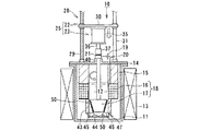
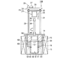
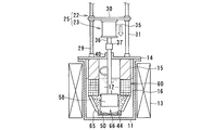
図7ないし図8は、本発明に係る電解装置の第3実施形態を示す全体構成図である。   7 to 8 are overall configuration diagrams showing a third embodiment of the electrolysis apparatus according to the present invention.

図7は、電解装置10Bの運用(運転前)の電極待機状態を示す断面図であり、図8は、電解装置10Bによる高速電解処理により得られる電解析出物の析出状態を示す断面図、図9は、電解析出物の回収状態を示す断面図である。第1実施形態に示される電解装置10と同じ構成および作用を有する部材・機器には同じ符号を付して説明を簡略化する。   FIG. 7 is a cross-sectional view showing an electrode standby state in operation (before operation) of the electrolysis apparatus 10B, and FIG. 8 is a cross-sectional view showing a precipitation state of electrolytic deposits obtained by high-speed electrolysis treatment by the electrolysis apparatus 10B. FIG. 9 is a cross-sectional view showing an electrolytic deposit recovery state. The members and devices having the same configuration and operation as the electrolysis apparatus 10 shown in the first embodiment are denoted by the same reference numerals, and the description is simplified.

図7に示されるように、第3実施形態の電解装置10Bは、るつぼ11の外周側に加熱ヒータ13が加熱源として設置されており、るつぼ11内にはアルカリ金属の塩化物である溶融塩12が満たされている。   As shown in FIG. 7, in the electrolysis apparatus 10 </ b> B of the third embodiment, a heater 13 is installed as a heating source on the outer peripheral side of the crucible 11, and a molten salt that is an alkali metal chloride is contained in the crucible 11. 12 is satisfied.

るつぼ11の頂部開口は上蓋14で覆われており、この上蓋14上に電極駆動装置25が設置される。電極駆動装置25は電極昇降機構22と電極回転機構23とで構成される。   The top opening of the crucible 11 is covered with an upper lid 14, and an electrode driving device 25 is installed on the upper lid 14. The electrode driving device 25 includes an electrode lifting mechanism 22 and an electrode rotating mechanism 23.

電極昇降機構22は設置台26上に設けられた昇降モータ27と、この昇降モータ27のモータ駆動軸に動力伝達機構28を介して接続されるスクリュシャフト29と、このスクリュシャフト29にねじ結合あるいはボールジョイントされた昇降ベース30とを有する。昇降ベース30はスクリュシャフト29の回転により昇降されるが、この昇降はガイドポール31によりベースの回転を拘束するように案内される。   The electrode elevating mechanism 22 includes an elevating motor 27 provided on an installation table 26, a screw shaft 29 connected to a motor drive shaft of the elevating motor 27 via a power transmission mechanism 28, and screw connection to the screw shaft 29 or And a ball-joined lifting base 30. The elevating base 30 is raised and lowered by the rotation of the screw shaft 29, and this elevating and lowering is guided by the guide pole 31 so as to restrain the rotation of the base.

電極昇降機構22の昇降ベース30に電極回転機構23が設けられる。電極回転機構23は、昇降ベース30の上面あるいは下面中央部に設けられた撹拌モータ35と、このモータ出力軸36にカップリング37を介して回転一体に連結された回転ドライブ軸38とを有し、この回転ドライブ軸38は軸受ボス40を介してるつぼ11内に入り、その下端に陰極58が可動電極として固定される。陰極58は、円筒状あるいはスリーブ状に構成される。   An electrode rotating mechanism 23 is provided on the lifting base 30 of the electrode lifting mechanism 22. The electrode rotation mechanism 23 has a stirring motor 35 provided at the center of the upper surface or the lower surface of the elevating base 30, and a rotary drive shaft 38 that is connected to the motor output shaft 36 through a coupling 37 so as to be integrally rotated. The rotary drive shaft 38 enters the crucible 11 through the bearing boss 40, and the cathode 58 is fixed to the lower end thereof as a movable electrode. The cathode 58 is configured in a cylindrical shape or a sleeve shape.

陰極58を取り囲むように外周には、円環状あるいはトーラス状の固定電極16が陽極として設け、電極装置60が構成される。この固定電極16の少なくとも内外周面、図示例では内外周面はメッシユ状の金網あるいはパンチングプレートを取り付けたバスケット形状に形成され、陽極バスケットとして構成される。陽極バスケット16は上蓋14に取り付けられた支持部材としての断熱部材15を介して設けられ、るつぼ11の内周面に沿うように配設される。   An annular or torus-shaped fixed electrode 16 is provided as an anode on the outer periphery so as to surround the cathode 58, and an electrode device 60 is configured. At least the inner and outer peripheral surfaces of the fixed electrode 16, in the illustrated example, the inner and outer peripheral surfaces are formed in a basket shape to which a mesh-shaped wire mesh or punching plate is attached, and are configured as an anode basket. The anode basket 16 is provided via a heat insulating member 15 as a support member attached to the upper lid 14, and is disposed along the inner peripheral surface of the crucible 11.

このようにして陽極16としての固定電極の上部には断熱部材15が、固定電極16の下部中央部にはスリーブ状あるいは円筒状のサポート部材43を介して析出物の回収容器46が設置されている。   In this way, the heat insulating member 15 is installed on the upper part of the fixed electrode as the anode 16, and the precipitate collection container 46 is installed on the lower central part of the fixed electrode 16 via the sleeve-like or cylindrical support member 43. Yes.

また、陽極16の内周面の上下2箇所に析出物の掻き取り用カッタ59が内方側に突出して設けられる。掻き取り用カッタ59は、陽極の上下2箇所に直径方向に対向して少なくとも2個設けてもよい。析出物の掻き取り用カッタ59は、陰極である可動電極58に析出された電解析出物50を陰極表面から掻き取るようになっている。この掻き取り用カッタ59と回収容器46とから析出物の回収装置61が構成される。   In addition, a scraping cutter 59 is provided at two locations on the inner peripheral surface of the anode 16 so as to protrude inward. At least two scraper cutters 59 may be provided at two upper and lower portions of the anode so as to face each other in the diametrical direction. The deposit scraping cutter 59 scrapes the electrolytic deposit 50 deposited on the movable electrode 58 serving as the cathode from the cathode surface. The scraping cutter 59 and the recovery container 46 constitute a precipitate recovery device 61.

さらに、電極装置60は、固定電極16である陽極と可動電極58である陰極との間に、図1に示すと同様な電解用電源回路(図示せず)により電源が供給されるようになっている。また、るつぼ11の上蓋14にはるつぼ11内に処理用ガスを供給するガス供給管とるつぼ11内のガスを排出(パージ)するガス排出管(共に図示せず)が設けられる。   Further, the electrode device 60 is supplied with power by an electrolysis power circuit (not shown) similar to that shown in FIG. 1 between the anode that is the fixed electrode 16 and the cathode that is the movable electrode 58. ing. The upper lid 14 of the crucible 11 is provided with a gas supply pipe for supplying processing gas into the crucible 11 and a gas discharge pipe (both not shown) for discharging (purging) the gas in the crucible 11.

次に、電解装置10Bの作用を説明する。   Next, the operation of the electrolyzer 10B will be described.

この電解装置10Bは、装置運用前に加熱ヒータ13に通電することで、るつぼ11内が加熱され、るつぼ11内に収容されたアルカリ金属の塩化物が加熱溶融され、高温・液状をなす溶融塩12として収容される。るつぼ11内の固定電極16には、使用済燃料である被覆管付切断燃料が収容される。この切断燃料は、切断面が半径方向内方を向くように収容される。固定電極16は、るつぼ11内の溶融塩12に浸漬された状態に設置される。   In this electrolyzer 10B, the inside of the crucible 11 is heated by energizing the heater 13 before the operation of the apparatus, and the alkali metal chloride accommodated in the crucible 11 is heated and melted to form a high temperature / liquid molten salt. 12 is accommodated. The fixed electrode 16 in the crucible 11 accommodates a cut fuel with a cladding tube, which is a spent fuel. This cut fuel is accommodated so that the cut surface faces radially inward. The fixed electrode 16 is installed in a state immersed in the molten salt 12 in the crucible 11.

しかして、電極駆動装置25の電極昇降機構22およびで機回転機構23を駆動させると、可動電極58は図7に示す後退した電極待機位置から回転しながら下降し、図8に示すように固定電極16の中央開口部に上方から挿入され、固定電極16に対応する電解析出位置まで下降し、この位置にセットされる。   When the machine rotating mechanism 23 is driven by the electrode lifting mechanism 22 and the electrode driving device 25, the movable electrode 58 descends while rotating from the retracted electrode standby position shown in FIG. 7, and is fixed as shown in FIG. It is inserted from above into the central opening of the electrode 16, descends to the electrolytic deposition position corresponding to the fixed electrode 16, and is set at this position.

図8に示す電解運転では、電極駆動装置25の昇降モータ27および撹拌モータ35を駆動させてるつぼ11内に可動電極58である陰極を回転させながら下降させる。この下降により陰極58は溶融塩12中に浸漬され、固定電極16である陽極に対向する位置で下降が停止せしめられる.
可動電極58である陰極は、引き続き回転が継続された状態で、両電極16,58間に電源を供給し、電圧を印加させる。この電圧印加により、UO,PuO等の顆粒状酸化物が電解析出物50として陰極58側に析出される。
In the electrolysis operation shown in FIG. 8, the cathode, which is the movable electrode 58, is lowered while rotating the crucible 11 that drives the elevating motor 27 and the agitation motor 35 of the electrode driving device 25. By this descent, the cathode 58 is immersed in the molten salt 12 and the descent is stopped at a position facing the anode which is the fixed electrode 16.
The cathode which is the movable electrode 58 supplies power between the electrodes 16 and 58 in a state where the rotation continues and applies a voltage. By applying this voltage, granular oxides such as UO 2 and PuO 2 are deposited on the cathode 58 side as electrolytic deposits 50.

電解析出物50は陰極58側に生じ始め、時間経過とともに次第に成長し、この電解析出物50の成長により陰極58側は陽極16側と接触が生じ、短絡が起き始める。   The electrolytic deposit 50 starts to be generated on the cathode 58 side and grows gradually with time. Due to the growth of the electrolytic deposit 50, the cathode 58 side comes into contact with the anode 16 side, and a short circuit starts to occur.

陰極58側と陽極16側に短絡が起き始めた時点あるいはその直前に陰極58を回転させた状態で電極昇降機構23を駆動させて陰極58を図8に示す状態から下降させる。   When the cathode 58 side and the anode 16 side start to short-circuit or immediately before the cathode 58 is rotated, the electrode lifting mechanism 23 is driven to lower the cathode 58 from the state shown in FIG.

図8に示す電解析出位置から陰極58を回転させながら下降させると、下部の析出物の掻き取り用カッタ59が陰極58の外表面に付着している電解析出物50と接触し、この電解析出物50を陰極58表面から徐々に掻き落としていく。最終的に図9に示すように回収位置に下降し、陰極58の電解析出物50を下部の掻き取り用カッタ59で除去される。   When the cathode 58 is lowered while rotating from the electrolytic deposition position shown in FIG. 8, the lower deposit scraping cutter 59 comes into contact with the electrolytic deposit 50 adhering to the outer surface of the cathode 58. The electrolytic deposit 50 is gradually scraped off from the surface of the cathode 58. Finally, as shown in FIG. 9, it descends to the collection position, and the electrolytic deposit 50 on the cathode 58 is removed by the lower scraping cutter 59.

下部の掻き取り用カッタ59で電解析出物50を除去した後、電極昇降機構22を反転駆動させ、陰極58を上昇させる。この陰極58の引き上げにより、上部の掻き取り用カッタ59で陰極58上に残された電解析出物を取り除く。   After the electrolytic deposit 50 is removed by the lower scraping cutter 59, the electrode lifting mechanism 22 is driven in reverse to raise the cathode 58. By pulling up the cathode 58, electrolytic deposits left on the cathode 58 are removed by the upper scraping cutter 59.

陰極58から電解析出物50が除去されると、陰極58は電極昇降機構22の駆動により下降させ、画7に示された固定電極16である陽極に対応したい位置に持ち来され、この電解析出位置で、再び電解運転が行なわれる。電解装置10Bは、陰極58側への電解析出物50の析出状態に応じて、電解析出および回収作業が繰り返される。   When the electrolytic deposit 50 is removed from the cathode 58, the cathode 58 is lowered by driving the electrode lifting mechanism 22, and is brought to a position corresponding to the anode which is the fixed electrode 16 shown in FIG. The electrolytic operation is performed again at the analysis output position. In the electrolyzer 10B, electrolytic deposition and recovery operations are repeated in accordance with the deposition state of the electrolytic deposit 50 on the cathode 58 side.

図8に示す電解作業により、陰極58に析出した電解析出物50が、下部および上部の掻き取り用カッタ59で掻き落とされると、陰極58から除去された顆粒状の電解析出物50はサポート部材59内を下降して回収容器46内に落下し、この回収容器46内に回収されて蓄積される。   When the electrolytic deposit 50 deposited on the cathode 58 by the electrolysis operation shown in FIG. 8 is scraped off by the lower and upper scraping cutters 59, the granular electrolytic deposit 50 removed from the cathode 58 is The support member 59 descends and falls into the collection container 46, and is collected and accumulated in the collection container 46.

析出物の回収容器46には電解析出物50が蓄積していき、使用済燃料のウラン等の有効成分が無くなったら、るつぼ11の上蓋14を開けて中の機器を外に取り出し、析出物の回収容器46に収容されている電解析出物50を回収し、取り出すようになっている。   When the electrolytic deposit 50 accumulates in the deposit collection container 46 and there is no active component such as uranium in the spent fuel, the upper lid 14 of the crucible 11 is opened and the equipment inside is taken out. The electrolytic deposit 50 accommodated in the recovery container 46 is recovered and taken out.

析出物の回収容器46から電解析出物50が取り出されると、電解装置10Bは次の使用済燃料の電解作業の準備がなされ、次の電解析出・回収作業が繰り返される。   When the electrolytic deposit 50 is taken out from the deposit collection container 46, the electrolyzer 10B is prepared for the next spent fuel electrolysis operation, and the next electrolytic deposition / recovery operation is repeated.

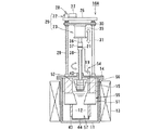
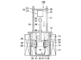
図10ないし図12は、本発明に係る電解装置の第4実施形態を示す全体構成図である。   10 to 12 are overall configuration diagrams showing a fourth embodiment of the electrolysis apparatus according to the present invention.

図10は、図1に示された電解装置10同様、電解装置10C運用前の状態を示す断面図である。図11は電解作業に伴うUO等の電解析出物の析出状態を、図12は析出された電解析出物の回収状態をそれぞれ示す断面図である。第1実施形態に示された電解装置10と同じ構成および作用には同じ符号を付し、説明を簡略化する。 FIG. 10 is a cross-sectional view showing a state before operation of the electrolyzer 10C, like the electrolyzer 10 shown in FIG. FIG. 11 is a cross-sectional view showing the state of precipitation of electrolytic deposits such as UO 2 accompanying the electrolysis operation, and FIG. 12 is a sectional view showing the state of recovery of the deposited electrolytic deposits. The same reference numerals are given to the same configurations and operations as those of the electrolysis apparatus 10 shown in the first embodiment, and the description will be simplified.

この実施形態に示された電解装置10Cは、るつぼ11の外側に加熱ヒータ13が加熱手段として設置されており、るつぼ11の内部はアルカリ金属塩化物等からなる溶融塩12で満たされている。るつぼ11の頂部開口は上蓋14で覆われており、この上蓋14に電極駆動装置25が設けられる。   In the electrolyzer 10C shown in this embodiment, a heater 13 is installed as a heating means on the outside of the crucible 11, and the inside of the crucible 11 is filled with a molten salt 12 made of alkali metal chloride or the like. The top opening of the crucible 11 is covered with an upper lid 14, and an electrode driving device 25 is provided on the upper lid 14.

電極駆動装置25は電極昇降機構22と電極回転機構23とにより構成される。電極昇降機構22は、設置台26上に設けられた昇降モータ27と、このモータ駆動力が動力伝達機構28を介して伝達されるスクリュシャフト29と、このスクリュシャフト29にねじ結合あるいはポールねじ結合された昇降ベース30とを有し、昇降ベース30はガイドポール31によりベース回転が拘束されて昇降せしめられる。   The electrode driving device 25 includes an electrode lifting mechanism 22 and an electrode rotating mechanism 23. The electrode elevating mechanism 22 includes an elevating motor 27 provided on an installation base 26, a screw shaft 29 to which the motor driving force is transmitted via a power transmission mechanism 28, and screw coupling or pole screw coupling to the screw shaft 29. The elevating base 30 is moved up and down with the base pole being restrained by the guide pole 31.

電極昇降機構22の昇降ベース30には電極回転機構23が設けられる。電極回転機構23は、昇降ベース30のベース表面あるいはベース下面の中央部に設けられた撹拌モータ35と、この撹拌モータ35のモータ出力軸36にカップリング37を介して回転一体に連結された回転ドライブ軸38とを有する。回転ドライブ軸38は上蓋14の軸受ボス40を貫いて下方に延び、その下端に可動電極58が陰極として固定される。可動電極58は円筒状あるいはスリーブ状に構成され、トーラス状あるいは円環状の固定電極16の中央開口部に出し入れ自在に挿入される。   An electrode rotating mechanism 23 is provided on the lifting base 30 of the electrode lifting mechanism 22. The electrode rotation mechanism 23 includes a stirring motor 35 provided on the base surface of the elevating base 30 or the central portion of the lower surface of the base, and a rotation integrally connected to the motor output shaft 36 of the stirring motor 35 via a coupling 37. And a drive shaft 38. The rotary drive shaft 38 extends downward through the bearing boss 40 of the upper lid 14, and a movable electrode 58 is fixed as a cathode at the lower end thereof. The movable electrode 58 is formed in a cylindrical shape or a sleeve shape, and is inserted into and removed from the central opening of the torus-shaped or annular fixed electrode 16.

固定電極16は、るつぼ11内に充填された溶融塩12中に浸漬され、トーラス状あるいは円環状に形成される陽極バスケットであり、陽極を構成している。この陽極バスケット16内に被覆管付使用済燃料である被覆管付切断燃料(図示せず)が収容される。被覆管付切断燃料は、切断面が半径方向内方を向くように収容される。   The fixed electrode 16 is an anode basket that is immersed in the molten salt 12 filled in the crucible 11 and formed in a torus shape or an annular shape, and constitutes an anode. In this anode basket 16, a cut fuel with a cladding tube (not shown), which is a spent fuel with a cladding tube, is accommodated. The cutting fuel with the cladding tube is accommodated so that the cut surface faces inward in the radial direction.

固定電極16である陽極バスケットは、電解装置10Cの上蓋14に保持部材としての断熱部材15を介して保持される一方、この陽極バスケット16に支持部材としての逆截頭円錐状あるいはトーラス状サポート部材65を介して受皿である析出物の回収容器46が設けられる。収納容器46は析出物の回収装置66を構成しており、陽極バスケット16の中央部下方に設けられる。陽極バスケット16は、少なくとも内表面にメッシュ状の金網あるいはパンチングプレートが設けられ、陽極バスケット16内に収納される使用済燃料としての被覆管付切断燃料が切断面を内側を向くように設置される。   The anode basket as the fixed electrode 16 is held on the upper lid 14 of the electrolysis apparatus 10C via a heat insulating member 15 as a holding member, while the anode basket 16 has a reverse frustoconical or torus-like support member as a support member. A precipitate collection container 46 serving as a tray is provided through 65. The storage container 46 constitutes a deposit recovery device 66 and is provided below the central portion of the anode basket 16. The anode basket 16 is provided with at least an inner surface provided with a mesh-like metal net or a punching plate, and the cut fuel with a cladding tube as spent fuel stored in the anode basket 16 is installed so that the cut surface faces the inside. .

また、電解装置10Cの上蓋14にはるつぼ11内の溶融塩12に反応ガスを吹き込むガス吹込管が、また、るつぼ11内のガスをパージ(排出)するガス排出管(共に図示せず)が設けられる一方、図1ないし図3に示す電解装置10の電解用電源回路19と同様な電源回路(図示せず)が設けられ、両電極16,58間に電源を供給し、電圧を印加させるようになっている。   Further, the upper lid 14 of the electrolyzer 10C has a gas blowing pipe for blowing reaction gas into the molten salt 12 in the crucible 11, and a gas discharge pipe (both not shown) for purging (discharging) the gas in the crucible 11. On the other hand, a power supply circuit (not shown) similar to the electrolysis power supply circuit 19 of the electrolysis apparatus 10 shown in FIGS. 1 to 3 is provided, and power is supplied between the electrodes 16 and 58 to apply a voltage. It is like that.

次に、電解装置10Cの作用を説明する。   Next, the operation of the electrolyzer 10C will be described.

電解装置10Cは、その運用前に加熱ヒータ13に通電することでるつぼ11内は加熱され、内部に収納された溶融塩12は500℃〜700℃の高温・液状となっている。   In the electrolyzer 10C, the crucible 11 is heated by energizing the heater 13 before its operation, and the molten salt 12 housed therein is in a high temperature / liquid state of 500 ° C. to 700 ° C.

図10に示された電解装置10Cが運用前の状態から電極駆動装置25を駆動させ、電極昇降機構22および電極回転機構23をモータ駆動させる。電極昇降機構22の昇降モータ27のモータ駆動により、そのモータ駆動力が動力伝達機構28を介してスクリュシャフト29を回転駆動させ、昇降ベース30を昇降させる。   The electrolyzer 10C shown in FIG. 10 drives the electrode driving device 25 from the state before operation, and drives the electrode lifting mechanism 22 and the electrode rotating mechanism 23 by a motor. With the motor drive of the lifting motor 27 of the electrode lifting mechanism 22, the motor driving force rotates the screw shaft 29 via the power transmission mechanism 28 and lifts the lifting base 30.

昇降ベース30の昇降はガイドポール31に案内され、ベースの回転を拘束するように昇降させる。昇降ベース30に設けられた電極回転機構23を駆動させることにより、回転ドライブ軸38の下端に設けられた可動電極としての円筒状あるいはスリーブ状陰極58は回転しながら下降し、図10に示す待機位置から図11に示される電解析出位置に持ち来され、この電解析出位置で電極昇降機構22の駆動が停止せしめられる。   The raising / lowering of the raising / lowering base 30 is guided by the guide pole 31, and is raised / lowered to restrain the rotation of the base. By driving the electrode rotating mechanism 23 provided on the elevating base 30, the cylindrical or sleeve-like cathode 58 as the movable electrode provided at the lower end of the rotary drive shaft 38 is lowered while rotating, and is in a standby state as shown in FIG. The electrode is brought from the position to the electrolytic deposition position shown in FIG. 11, and the drive of the electrode lifting mechanism 22 is stopped at this electrolytic deposition position.

電解装置10Cは、陰極である可動電極58が電解析出位置をとるとき、電極昇降機構22の下降が停止された状態で回転が継続され、電動電極である陰極58は引き続き回転したままの状態に保たれて両電極16,58に電源が供給される。   In the electrolyzer 10C, when the movable electrode 58, which is a cathode, takes an electrolytic deposition position, the electrolysis apparatus 10C continues to rotate with the lowering of the electrode lifting mechanism 22 stopped, and the cathode 58, which is an electric electrode, continues to rotate. Thus, power is supplied to both electrodes 16 and 58.

両電極16,58間に電源が供給されると、陽極バスケット16内に収容された被覆管付切断燃料は、溶融塩12内に溶解して溶融する。溶融塩12に溶解した溶液は、両電極16,58間への電圧印加によって陰極58側にUO,PuO等の顆粒状酸化物である電解析出物50が析出し始め、析出した電解析出物50は陰極表面に次第に堆積していく。 When power is supplied between the electrodes 16 and 58, the cut fuel with the cladding tube accommodated in the anode basket 16 is dissolved in the molten salt 12 and melted. The solution dissolved in the molten salt 12 starts to deposit electrolytic deposits 50, which are granular oxides such as UO 2 and PuO 2 , on the cathode 58 side by applying a voltage between the electrodes 16 and 58. The analysis product 50 is gradually deposited on the cathode surface.

電解析出物50の成長により陰極表面に析出していくと、陰極58側は電解析出物50を介して陽極16側と接触が生じ、短絡が起き始める。   As the electrolytic deposit 50 grows and deposits on the cathode surface, the cathode 58 side comes into contact with the anode 16 side via the electrolytic deposit 50 and a short circuit starts to occur.

陰極58が陽極16側と短絡が生じ始めると、陰極58の回転駆動をキープした状態で、電極昇降機構22をモータ駆動させ、陰極58を図11に示す電解析出位置から下降させ、図12に示す電解析出物50の回収位置に持ち来す。   When the cathode 58 starts to short-circuit with the anode 16 side, the electrode lifting mechanism 22 is driven by the motor while keeping the rotation drive of the cathode 58, and the cathode 58 is lowered from the electrolytic deposition position shown in FIG. To the collection position of the electrolytic deposit 50 shown in FIG.

陰極58が陽極(陽極バスケット)16から抜け切った所で下降を停止させ、この下降停止位置で電極回転機構23の撹拌モータ35をより高速に回転させ、回転ドライブ軸38の下端に固定された可動電極58に回転による遠心力を付与する。この回転遠心力により陰極58表面に付着した電解析出物50は遠心力により陰極58の外表面から引き剥がされて周囲に飛散する。   The descent is stopped when the cathode 58 is completely removed from the anode (anode basket) 16, and the stirring motor 35 of the electrode rotation mechanism 23 is rotated at a higher speed at the descent stop position and fixed to the lower end of the rotary drive shaft 38. A centrifugal force by rotation is applied to the movable electrode 58. The electrolytic deposit 50 adhered to the surface of the cathode 58 by this rotational centrifugal force is peeled off from the outer surface of the cathode 58 by the centrifugal force and scattered around.

周囲に飛散した電解析出物50は、逆截頭円錐状あるいはロート状のサポート部材60に案内されて下方に落下し、析出物の回収容器66に掻き集められる。   The electrolytic deposit 50 scattered around is guided downward by the inverted frustoconical or funnel-shaped support member 60 and falls downward, and is collected in the deposit collection container 66.

陰極58表面に付着した電解析出物50が剥離されて飛散し、回収容器46に掻き集められた後、電極昇降機構22を駆動させて陰極58を上昇させ、図11に示された陽極16に対応する電解析出位置に持ち来す。この電解析出位置で再び電解運転を行ない、電解析出物50を析出させた後、電解析出物50の回収位置に持ち来し、この回収作業を行なう。   After the electrolytic deposit 50 adhered to the surface of the cathode 58 is peeled off and scattered and collected in the collection container 46, the electrode lifting mechanism 22 is driven to raise the cathode 58, and the anode 16 shown in FIG. Bring to the corresponding electrolytic deposition position. The electrolytic operation is performed again at the electrolytic deposition position to deposit the electrolytic deposit 50, and then the electrolytic deposit 50 is brought to the collection position to perform the recovery operation.

電解装置10Cによる電解析出・回収作業を繰り返し、電解析出物50を回収容器46に回収させた後、被覆管付使用済燃料に含まれるウラン等の有効成分が無くなったら、るつぼ11の上蓋14を開け、るつぼ11内の収納機器を外部に取り出す。るつぼ11内機器を外部に取り出すことにより、回収容器46内に蓄積された電解析出物50を外部に取り出して回収する。   After the electrolytic deposition / recovery operation by the electrolyzer 10C is repeated and the electrolytic deposit 50 is recovered in the recovery container 46, when the active ingredient such as uranium contained in the spent fuel with the cladding tube disappears, the upper cover of the crucible 11 14 is opened and the storage device in the crucible 11 is taken out. By taking out the equipment in the crucible 11 to the outside, the electrolytic deposit 50 accumulated in the collection container 46 is taken out and collected.

電解析出物50の外部への取出し、回収により、一連の電解析出・回収作業が終了し、電解装置10Cは次の使用済燃料の処理のための準備が行なわれ、以後、同様な電解析出・回収作業が繰り返される。   The series of electrolytic deposition / recovery operations are completed by taking out and collecting the electrolytic deposit 50 to the outside, and the electrolyzer 10C is prepared for the treatment of the next spent fuel. Analyzing / collecting is repeated.

図13および図14は、本発明の各実施形態の電解装置に備えられる電極装置の実施例を示すものである。   FIG. 13 and FIG. 14 show examples of the electrode device provided in the electrolyzer of each embodiment of the present invention.

この実施例に示された電極装置70は、トーラス状あるいは円環状の固定電極71と、この固定電極71の中央開口部に出し入れ可能に案内される可動電極72とを有し、可動電極72の外表面に析出物の掻き取り用カッタ73を設けたものである。   The electrode device 70 shown in this embodiment has a torus-shaped or annular fixed electrode 71 and a movable electrode 72 guided so as to be able to be inserted into and removed from the central opening of the fixed electrode 71. A precipitate scraping cutter 73 is provided on the outer surface.

固定電極71と可動電極72との間には各紙実施例に示された電解用電源回路19と同様な電源回路(図示せず)により電源が供給され、電圧が印加される。両電極62,63から電極装置75を構成しており、この電極装置75は、電解作業時には溶融塩(図示せず)中に浸漬される。   A power supply is supplied between the fixed electrode 71 and the movable electrode 72 by a power supply circuit (not shown) similar to the electrolysis power supply circuit 19 shown in each paper embodiment, and a voltage is applied. Both electrodes 62 and 63 constitute an electrode device 75, and this electrode device 75 is immersed in a molten salt (not shown) during electrolysis.

固定電極71は陰極を構成しており、この固定電極71の内周面は逆截頭円錐形状に形成される。固定電極71の内周面内に可動電極72が出し入れ自在に収納される。可動電極72を固定電極71内に挿入したとき、両電極間に逆截頭円錐形状あるいはロート状の電極間間隙が形成される。   The fixed electrode 71 forms a cathode, and the inner peripheral surface of the fixed electrode 71 is formed in a reverse truncated cone shape. The movable electrode 72 is housed in the inner peripheral surface of the fixed electrode 71 so as to be freely inserted and removed. When the movable electrode 72 is inserted into the fixed electrode 71, a reverse frustoconical or funnel-shaped interelectrode gap is formed between the two electrodes.

可動電極72は陽極を構成しており、図示しない電極駆動装置により、図1〜図12の電解装置10〜10Cと同様、固定電極71から後退した待機位置と、固定電極72に対応(対向)する電解析出装置と、電解析出物を掻き落とす析出物の回収位置との間を上下に昇降自在かつ軸線廻りに回転自在に設けられる。   The movable electrode 72 constitutes an anode, and corresponds to the stand-by position retracted from the fixed electrode 71 and the fixed electrode 72 (opposite) by an electrode driving device (not shown) as in the electrolysis devices 10 to 10C of FIGS. Between the electrolytic deposition apparatus and the deposit collection position for scraping the electrolytic deposit, and is vertically movable up and down and rotatable around the axis.

可動電極72の外表面は、固定電極71の内周面に対応するように逆截頭円錐形状に形成され、可動電極72の外表面は、少なくとも1箇所に掻き取り用カッタ73が設けられる。掻き取り用カッタ73は可動電極72の外表面に、直径方向に対向して、複数個設けてもよい。   The outer surface of the movable electrode 72 is formed in a reverse frustoconical shape so as to correspond to the inner peripheral surface of the fixed electrode 71, and the scraping cutter 73 is provided on at least one location on the outer surface of the movable electrode 72. A plurality of scraping cutters 73 may be provided on the outer surface of the movable electrode 72 so as to face each other in the diametrical direction.

掻き取り用カッタ73のカッタ刃は、陽極である可動電極72の外表面から半径方向外方に突出する一方、可動電極72の高さ方向にヘリカル状あるいは螺旋状に湾曲している。図1および図14(A)には螺旋状あるいはヘリカル状の掻き取り用カッタ73を一体に設けた例を示したが、図14(B)に示すように、掻き取り用カッタ74は、直刃状のカッタ刃を備えるようにしてもよい。   The cutter blade of the scraping cutter 73 protrudes outward in the radial direction from the outer surface of the movable electrode 72 as an anode, and is curved in a helical shape or a spiral shape in the height direction of the movable electrode 72. FIG. 1 and FIG. 14A show an example in which a spiral or helical scraping cutter 73 is integrally provided. However, as shown in FIG. You may make it provide a blade-shaped cutter blade.

図13および図14に開示された電極装置70は、各実施形態に示された電解装置10(10A〜10C)に組み込まれて用いられる。   The electrode device 70 disclosed in FIGS. 13 and 14 is used by being incorporated in the electrolysis device 10 (10A to 10C) shown in each embodiment.

電極装置70は、電極駆動装置(図示せず)により可動電極72を固定電極71内に対応させ、電解析出位置に持ち来した状態(図13参照)で、陽極である可動電極72を回転させ、両電極71,72間に電源を供給する。   The electrode device 70 rotates the movable electrode 72 as an anode in a state where the movable electrode 72 is brought into the fixed electrode 71 by an electrode driving device (not shown) and brought to the electrolytic deposition position (see FIG. 13). And power is supplied between the electrodes 71 and 72.

両電極71,72間に電源が供給され、電圧が印加されると、電解を始めて使用済燃料のウラン等の有効成分が溶融塩に溶解し、溶解した溶液からUO,PuO等の顆粒状酸化物である電解析出物50が陰極71部に生じ始める。 When power is supplied between the electrodes 71 and 72 and a voltage is applied, an active ingredient such as uranium of spent fuel is dissolved in the molten salt by starting electrolysis, and granules such as UO 2 and PuO 2 are dissolved from the dissolved solution. The electrolytic deposit 50, which is an oxide of oxide, begins to form at the cathode 71 part.

電解析出物50の成長により陰極71側に析出された電解析出物50を介して陰極71が陽極72側に接触し始めると、図示しない電極駆動装置(電極昇降機構と電極回転機構)を駆動させて陽極である可動電極72を回転させながら下降させる。   When the cathode 71 starts to come into contact with the anode 72 side through the electrolytic deposit 50 deposited on the cathode 71 side due to the growth of the electrolytic deposit 50, an electrode driving device (electrode lifting mechanism and electrode rotating mechanism) (not shown) is installed. The movable electrode 72 which is an anode is driven and lowered while rotating.

可動電極72を回転させながら下降させると、陽極に取り付けられて析出物の掻き取り用カッタ73が、電解析出物50に徐々に接触しながら、陰極71の表面から削り落としていく。このとき、掻き取り用カッタ73は螺旋形状あるいはヘリカル形状のカッタ刃により、削られた電解析出物50を外に押し出すように作用し、効率よく電解析出物50の除去あるいは回収を行なうことができる。   When the movable electrode 72 is lowered while rotating, the precipitate scraping cutter 73 attached to the anode is scraped off from the surface of the cathode 71 while gradually contacting the electrolytic precipitate 50. At this time, the scraping cutter 73 acts to extrude the scraped electrolytic deposit 50 to the outside with a spiral or helical cutter blade, and the electrolytic deposit 50 is efficiently removed or collected. Can do.

図15ないし図17は、図13に示された電極装置の各変形例を示すものである。   15 to 17 show modifications of the electrode device shown in FIG.

図15は、電極装置70Aの第1変形例を示すものである。この電極装置70Aは、固定電極76をトーラス状あるいは円環状、円筒状のバスケット形状の陽極に構成し、この陽極バスケット76の内側に円筒状あるいはスリーブ状の可動電極77を出し入れ可能に収納させ得るようにしたものである。可動電極77は、陰極を構成している。   FIG. 15 shows a first modification of the electrode device 70A. In this electrode device 70A, the fixed electrode 76 is configured as a torus-shaped, annular, or cylindrical basket-shaped anode, and a cylindrical or sleeve-shaped movable electrode 77 can be accommodated inside the anode basket 76 so as to be able to be put in and out. It is what I did. The movable electrode 77 constitutes a cathode.

陽極バスケット76は、少なくとも内周面がメッシュ状の金網あるいはパンチングプレートで覆われて構成される。図15には陽極バスケット66の内周面および外周面を金網あるいはパンチングプレートで覆設した例を示す。   The anode basket 76 is configured such that at least an inner peripheral surface is covered with a mesh-like metal net or a punching plate. FIG. 15 shows an example in which the inner peripheral surface and the outer peripheral surface of the anode basket 66 are covered with a metal mesh or a punching plate.

陽極バスケット76は、内部に補強を兼ねる放射状に仕切壁78を備え、この仕切壁78で仕切られたバスケット内部に使用済燃料である被覆管付切断燃料79が収納される。この被覆管付切断燃料はバスケット内部に放射状に収納され、燃料切断面が陰極を構成する可動電極7を向くようにセットされる。   The anode basket 76 is provided with a partition wall 78 in a radial pattern that also serves as a reinforcement, and a cut fuel 79 with a cladding tube, which is a spent fuel, is stored in the basket partitioned by the partition wall 78. The cut fuel with the cladding tube is stored radially inside the basket, and is set so that the fuel cut surface faces the movable electrode 7 constituting the cathode.

図16は、電極装置70Bの第2変形例を示すものである。   FIG. 16 shows a second modification of the electrode device 70B.

この電極装置70Bは、円環状あるいはトーラス状、円筒状の固定電極(図示せず)を陰極に、固定電極の内側に配設可能な可動電極80を陽極に構成したものである。   In this electrode device 70B, an annular, torus-shaped, or cylindrical fixed electrode (not shown) is used as a cathode, and a movable electrode 80 that can be disposed inside the fixed electrode is used as an anode.

可動電極80は、図16に示すようにボックス状のバスケットを平断面十字型に配設して十字型陽極バスケットを構成し、陽極バスケット80内に使用済燃料である被覆管付切断燃料69を収納したものである。被覆管付切断燃料79は図16に示すように周方向を向くように配設しても、また、放射状に配設してもよい。   As shown in FIG. 16, the movable electrode 80 has a box-shaped basket arranged in a cross-shaped cross section to form a cross-shaped anode basket, and a cut fuel 69 with a cladding tube, which is spent fuel, is used in the anode basket 80. It is what was stored. The cut fuel 79 with a cladding tube may be disposed so as to face the circumferential direction as shown in FIG. 16, or may be disposed radially.

図17は、電極装置61Cの第3変形例を示すものである。   FIG. 17 shows a third modification of the electrode device 61C.

この電極装置61Cは、円環状あるいはトーラス状、円筒状の固定電極(図示せず)を陰極に、固定電極の内側に配設可能な可動電極を陽極に構成したものである。   The electrode device 61C has an annular, torus-shaped, or cylindrical fixed electrode (not shown) as a cathode, and a movable electrode that can be arranged inside the fixed electrode as an anode.

可動電極71は、平面形状が扇型をなすボックス状のバスケットを、放射状に配設して陽極バスケットを構成し、この陽極バスケット81内に使用済燃料である被覆管付切断燃料69を放射状に収容したものである。   In the movable electrode 71, a box-shaped basket having a fan-shaped planar shape is radially arranged to constitute an anode basket, and the cut fuel 69 with a cladding tube, which is a spent fuel, is radially arranged in the anode basket 81. It is what was contained.

図17に示された可動電極81は、扇型ボックス形状を組み合せた陽極バスケットのバスケット内部に被覆管付使用済切断燃料79を放射状に収容したものである。   A movable electrode 81 shown in FIG. 17 is one in which spent cutting fuel 79 with a cladding tube is radially accommodated in the basket of an anode basket combined with a fan-shaped box shape.

図15ないし図17に示された電極装置の各変形例によれば、電極装置70,70A〜70Cの両電極間に円筒状あるいはスリーブ状の電極間間隙を形成し、この間隙を常時所定値に保つことができる。   According to each modification of the electrode device shown in FIGS. 15 to 17, a cylindrical or sleeve-like interelectrode gap is formed between both electrodes of the electrode devices 70, 70A to 70C, and this gap is always set to a predetermined value. Can be kept in.

本発明に係る電解装置の第1実施形態を示す全体構成図。BRIEF DESCRIPTION OF THE DRAWINGS The whole block diagram which shows 1st Embodiment of the electrolyzer based on this invention. 図1に示された電解装置による電解析出状態を示す断面図。Sectional drawing which shows the electrolytic deposition state by the electrolysis apparatus shown by FIG. 図1に示された電解装置による電解析出物の回収状態を示す断面図。Sectional drawing which shows the collection | recovery state of the electrolytic deposit by the electrolysis apparatus shown by FIG. 本発明に係る電解装置の第2実施形態を示す全体構成図。The whole block diagram which shows 2nd Embodiment of the electrolyzer based on this invention. 図4に示された電解装置による電解析出状態を示す断面図。Sectional drawing which shows the electrolytic deposition state by the electrolysis apparatus shown by FIG. 図4に示された電解装置による電解析出物の回収状態を示す断面図。Sectional drawing which shows the collection | recovery state of the electrolytic deposit by the electrolysis apparatus shown by FIG. 本発明に係る電解装置の第3実施形態を示す全体構成図。The whole block diagram which shows 3rd Embodiment of the electrolyzer based on this invention. 図7に示された電解装置による電解析出状態を示す断面図。Sectional drawing which shows the electrolytic deposition state by the electrolytic device shown by FIG. 図7に示された電解装置による電解析出物の回収状態を示す断面図。Sectional drawing which shows the collection | recovery state of the electrolytic deposit by the electrolysis apparatus shown by FIG. 本発明に係る電解装置の第4実施形態を示す全体構成図。The whole block diagram which shows 4th Embodiment of the electrolyzer based on this invention. 図10に示された電解装置による電解析出状態を示す断面図。Sectional drawing which shows the electrolytic deposition state by the electrolysis apparatus shown by FIG. 図10に示された電解装置による電解析出物の回収状態を示す断面図。Sectional drawing which shows the collection | recovery state of the electrolytic deposit by the electrolysis apparatus shown by FIG. 本発明に係る電解装置に組み込まれる電極装置の第1実施例を一部破断して示す斜視図。The perspective view which partially fractures and shows the 1st Example of the electrode apparatus integrated in the electrolytic device which concerns on this invention. (A)および(B)は電極装置の可動電極に備えられる析出物の掻き取り用カッタをそれぞれ示す図。(A) And (B) is a figure which respectively shows the cutter for scraping off of the deposit with which the movable electrode of an electrode apparatus is equipped. 前記電極装置の第1変形例を示す斜視図。The perspective view which shows the 1st modification of the said electrode apparatus. 前記電極装置の第2変形例を示す斜視図。The perspective view which shows the 2nd modification of the said electrode apparatus. 前記電極装置の第3変形例を示す斜視図。The perspective view which shows the 3rd modification of the said electrode apparatus.

符号の説明Explanation of symbols

10,10A 電解装置
11 るつぼ
12 溶融塩
13 加熱ヒータ(加熱手段)
14 上蓋
15 断熱部材(サポート部材)
16 陽極バスケット(陽極、固定電極)
17 電極(陰極、回転電極)
18 電極装置
19 電解用電源
20 電解用電源回路
21 スリップリング
22 電極昇降機構
23 電極回転機構
25 電極駆動装置
26 設置台
27 昇降モータ
28 動力伝達機構
29 スクリュシャフト
30 昇降ベース
31 ガイドポール
35 撹拌モータ
36 モータ駆動軸
37 カップリング
38 回転ドライブ軸
40 軸受ボス
43 サポート部材
44 回収容器
45 掻き取り用カッタ
47,50 回収装置
50 電解析出物
51 固定電極(陰極)
52 可動電極(陽極、陽極バスケット)
54 電解用電源回路
56 掻き取り用カッタ
58 可動電極(陰極)
59 掻き取り用カッタ
60 サポート部材
60 電極装置
61 回収装置
65 サポート部材
71 固定電極(陰極)
72 可動電極(陽極)
73,74 掻き取り用カッタ
75 電極装置
59 被覆管付切断燃料
76 固定電極(陽極)
77 可動電極(陰極)
78 仕切壁
79 被覆管付切断燃料
80,81 可動電極(陽極、陽極バスケット)
10, 10A Electrolytic device 11 Crucible 12 Molten salt 13 Heater (heating means)
14 Upper lid 15 Thermal insulation member (support member)
16 Anode basket (anode, fixed electrode)
17 electrodes (cathode, rotating electrode)
18 Electrode Device 19 Electrolytic Power Supply 20 Electrolytic Power Supply Circuit 21 Slip Ring 22 Electrode Elevating Mechanism 23 Electrode Rotating Mechanism 25 Electrode Driving Device 26 Installation Table 27 Elevating Motor 28 Power Transmission Mechanism 29 Screw Shaft 30 Elevating Base 31 Guide Pole 35 Agitation Motor 36 Motor drive shaft 37 Coupling 38 Rotation drive shaft 40 Bearing boss 43 Support member 44 Recovery container 45 Scraping cutters 47, 50 Recovery device 50 Electrodeposited matter 51 Fixed electrode (cathode)
52 Movable electrodes (anode, anode basket)
54 Electrolytic power circuit 56 Scraping cutter 58 Movable electrode (cathode)
59 Cutter 60 for scraping Support member 60 Electrode device 61 Recovery device 65 Support member 71 Fixed electrode (cathode)
72 Movable electrode (anode)
73, 74 Scraping cutter 75 Electrode device 59 Cutting fuel with cladding tube 76 Fixed electrode (anode)
77 Movable electrode (cathode)
78 Partition wall 79 Cutting fuel with cladding tube 80, 81 Movable electrode (anode, anode basket)

Claims (10)

溶融塩を収納するるつぼと、
このるつぼを加熱する加熱手段と、
前記るつぼ内に収容され、陽極と陰極とを有する電極装置と、
この電極装置の両電極間に電源を供給する電解用電源回路と、
前記電極装置の可動電極を昇降可能かつ回転可能に駆動する電極駆動装置と、
前記両電極に電源を供給することにより、陰極側に析出する電解析出物を回収する回収装置とを有し、
前記電極装置はるつぼ内の溶融塩に浸漬可能に設けられたトーラス状あるいは円環状の固定電極と、この固定電極の内側に出し入れ可能に配設される可動電極とを有し、前記両電極の一方を陽極に、その他方を陰極に構成し、
前記電極装置の固定電極は陽極あるいは陰極に、可動電極は陰極あるいは陽極にそれぞれ形成され、
前記可動電極は、前記電極駆動装置により固定電極から上方に後退した待機位置と、固定電極に対応する電解析出位置と、固定電極より下降した電解析出物の回収位置との間を選択的に移動せしめられるように構成されたことを特徴とする電解装置。
A crucible for storing molten salt;
Heating means for heating the crucible;
An electrode device housed in the crucible and having an anode and a cathode;
An electrolysis power supply circuit for supplying power between both electrodes of the electrode device;
An electrode driving device for driving the movable electrode of the electrode device to be movable up and down and rotatable;
A recovery device for recovering the electrolytic deposits deposited on the cathode side by supplying power to both electrodes;
The electrode device has a torus-shaped or annular fixed electrode provided so as to be immersed in the molten salt in the crucible, and a movable electrode disposed so as to be able to be taken in and out of the fixed electrode. Configure one as the anode and the other as the cathode ,
The fixed electrode of the electrode device is formed on the anode or the cathode, and the movable electrode is formed on the cathode or the anode, respectively.
The movable electrode is selectively between a standby position retracted upward from the fixed electrode by the electrode driving device, an electrolytic deposition position corresponding to the fixed electrode, and a collection position of the electrolytic deposit descending from the fixed electrode. An electrolysis apparatus configured to be moved to a position.
前記陽極は金網、パンチングメタル等の開孔部材を備えたバスケット形状の陽極バスケットに構成され、上記陽極バスケットのバスケット内部に被覆管付使用済燃料が収納された請求項1記載の電解装置。 2. The electrolysis apparatus according to claim 1, wherein the anode is configured as a basket-shaped anode basket having an opening member such as a metal mesh or punching metal, and spent fuel with a cladding tube is accommodated inside the basket of the anode basket. 前記回収装置は、両電極間への電源供給により、陰極側に析出されたUO等の電解析出物を陰極表面から掻き取る析出物の掻き取り用カッタと、この掻き取り用カッタで掻き落とされた電解析出物を回収する回収容器とを備えた請求項1記載の電解装置。 The recovery device includes a scraping cutter for scraping off electrolytic deposits such as UO 2 deposited on the cathode side from the cathode surface by supplying power between both electrodes, and scraping with the scraping cutter. The electrolysis apparatus according to claim 1, further comprising a collection container for collecting the dropped electrolytic deposit. 前記電極装置は、トーラス状あるいは円環状の固定電極と、この固定電極の内側に出し入れ可能な円筒状あるいはスリーブ状の可動電極とを有し、
前記固定電極は内周面が円筒状あるいはスリーブ状に形成され、この固定電極と可動電極の間にスリーブ状、リング状の電極間間隙が形成された請求項1記載の電解装置。
The electrode device has a torus-shaped or annular fixed electrode and a cylindrical or sleeve-shaped movable electrode that can be taken in and out of the fixed electrode,
2. The electrolysis apparatus according to claim 1, wherein the fixed electrode has an inner peripheral surface formed in a cylindrical shape or a sleeve shape, and a sleeve-like or ring-like inter-electrode gap is formed between the fixed electrode and the movable electrode.
溶融塩を収納するるつぼと、
このるつぼを加熱する加熱手段と、
前記るつぼ内に収容され、陽極と陰極とを有する電極装置と、
この電極装置の両電極間に電源を供給する電解用電源回路と、
前記電極装置の可動電極を昇降可能かつ回転可能に駆動する電極駆動装置と、
前記両電極に電源を供給することにより、陰極側に析出する電解析出物を回収する回収装置とを有し、
前記電極装置はるつぼ内の溶融塩に浸漬可能に設けられたトーラス状あるいは円環状の固定電極と、この固定電極の内側に出し入れ可能に配設される可動電極とを有し、前記両電極の一方を陽極に、その他方を陰極に構成し
前記電極装置は、トーラス状あるいは円環状の固定電極と、この固定電極の内側に出し入れ可能な可動電極とを有し、
前記固定電極は内周面が逆截頭円錐形状に形成され、この固定電極の内側に収納可能な可動電極は外周面が逆截頭円錐形状に形成され、両電極間に逆截頭円錐形状あるいはロート形状の電極間間隙が形成されたことを特徴とする電解装置。
A crucible for storing molten salt;
Heating means for heating the crucible;
An electrode device housed in the crucible and having an anode and a cathode;
An electrolysis power supply circuit for supplying power between both electrodes of the electrode device;
An electrode driving device for driving the movable electrode of the electrode device to be movable up and down and rotatable;
A recovery device for recovering the electrolytic deposits deposited on the cathode side by supplying power to both electrodes;
The electrode device has a torus-shaped or annular fixed electrode provided so as to be immersed in the molten salt in the crucible, and a movable electrode disposed so as to be able to be taken in and out of the fixed electrode. Configure one as the anode and the other as the cathode ,
The electrode device has a torus-shaped or annular fixed electrode, and a movable electrode that can be taken in and out of the fixed electrode,
The fixed electrode has an inner peripheral surface formed in a reverse frustoconical shape, and the movable electrode that can be accommodated inside the fixed electrode has an outer peripheral surface formed in an inverted frustoconical shape. Alternatively, an electrolytic apparatus in which a funnel-shaped interelectrode gap is formed.
前記可動電極は陽極を構成し、可動電極の外周面に析出物の掻き取り用カッタを電極軸方向にヘリカル状、直線状あるいはテーパ状に設け、前記掻き取り用カッタで掻き取られた電解析出物を可動電極下方の回収容器に回収させた請求項4または5記載の電解装置。 The movable electrode constitutes an anode, and a scraping cutter is provided on the outer peripheral surface of the movable electrode in a helical, linear, or tapered shape in the electrode axial direction, and the electrical analysis is scraped off by the scraping cutter. The electrolyzer according to claim 4 or 5 , wherein the extract is collected in a collection container below the movable electrode. 前記固定電極は陽極を構成し、前記固定電極の内周面側の少なくとも下部あるいは下方に析出物の掻き取り用カッタを設け、上記掻き取り用カッタで掻き取られた電解析出物を可動電極下方の回収容器に回収させた請求項4または5記載の電解装置。 The fixed electrode constitutes an anode, a cutter for scraping the deposit is provided at least below or below the inner peripheral surface of the fixed electrode, and the electrolytic deposit scraped by the scraping cutter is moved to the movable electrode. The electrolyzer according to claim 4 or 5 , wherein the electrolyzer is recovered in a lower recovery container. 前記電極装置は、トーラス状あるいは円環状の固定電極が陽極を構成してバスケット形状に形成され、
上記固定電極の陽極バスケットはバスケット内部に被覆管付使用済切断燃料が切断面を陰極を向けて収容され、上記陽極バスケットの少なくとも内周面は金網、パンチングメタル等の開孔部材で構成された請求項1記載の電解装置。
In the electrode device, a torus-shaped or annular fixed electrode constitutes an anode and is formed in a basket shape,
The anode basket of the fixed electrode contains spent cutting fuel with a cladding tube inside the basket with the cut surface facing the cathode, and at least the inner peripheral surface of the anode basket is composed of an opening member such as a metal mesh or punching metal. The electrolyzer according to claim 1.
前記電極装置は、固定電極の内側に出し入れ可能な可動電極が陽極に構成され、上記可動電極を構成する陽極バスケットは、平面視トーラス形状あるいは円環形状に、または平面視矩形あるいは扇型のボックスを放射状あるいは十字型に配設した構成とした請求項1記載の電解装置。 In the electrode device, a movable electrode that can be taken in and out of a fixed electrode is configured as an anode, and an anode basket that configures the movable electrode has a torus shape or an annular shape in plan view, or a rectangular or fan-shaped box in plan view The electrolysis apparatus according to claim 1, wherein the structure is arranged in a radial or cross shape. 前記電極駆動装置は、可動電極を固定電極から下降させ、固定電極下方の析出物の回収位置で電解析出位置より高速回転させ、電解析出物を遠心力作用で陰極を構成する可動電極の外周面より飛散させた請求項1記載の電解装置。 The electrode driving device lowers the movable electrode from the fixed electrode, rotates it at a high speed from the electrolytic deposition position at the deposit collection position below the fixed electrode, and moves the electrolytic deposit to form the cathode by centrifugal action. The electrolyzer according to claim 1 , wherein the electrolyzer is scattered from the outer peripheral surface.
JP2005141892A 2005-05-13 2005-05-13 Electrolyzer Expired - Lifetime JP4734026B2 (en)

Priority Applications (1)

Application Number Priority Date Filing Date Title
JP2005141892A JP4734026B2 (en) 2005-05-13 2005-05-13 Electrolyzer

Applications Claiming Priority (1)

Application Number Priority Date Filing Date Title
JP2005141892A JP4734026B2 (en) 2005-05-13 2005-05-13 Electrolyzer

Publications (2)

Publication Number Publication Date
JP2006314958A JP2006314958A (en) 2006-11-24
JP4734026B2 true JP4734026B2 (en) 2011-07-27

Family

ID=37536084

Family Applications (1)

Application Number Title Priority Date Filing Date
JP2005141892A Expired - Lifetime JP4734026B2 (en) 2005-05-13 2005-05-13 Electrolyzer

Country Status (1)

Country Link
JP (1) JP4734026B2 (en)

Cited By (1)

* Cited by examiner, † Cited by third party
Publication number Priority date Publication date Assignee Title
KR20190135589A (en) * 2018-05-29 2019-12-09 무진기공주식회사 Cavitation reactor for biodiesel production in which the clearance between rotating body and fixed body is adjusted

Families Citing this family (11)

* Cited by examiner, † Cited by third party
Publication number Priority date Publication date Assignee Title
KR100880731B1 (en) * 2007-06-04 2009-02-02 한국원자력연구원 Continuous Electrolytic Refinery of Metal Uranium
JP5483867B2 (en) * 2008-11-25 2014-05-07 日立Geニュークリア・エナジー株式会社 Method for recovering metallic fuel material from spent fuel and method for reprocessing spent fuel
JP5591645B2 (en) * 2010-09-22 2014-09-17 株式会社東芝 Spent nuclear fuel reprocessing apparatus and reprocessing method thereof
CN101976853A (en) * 2010-11-09 2011-02-16 张建洲 Wind power hydrogen production regulation, control and grid-connection system
JP5787785B2 (en) * 2012-02-20 2015-09-30 株式会社東芝 Molten salt electrolysis apparatus and molten salt electrolysis method
KR101397935B1 (en) 2012-11-29 2014-05-23 한국수력원자력 주식회사 Electrolytic reduction device having multiplr circuits and method for driving the same
GB2545185A (en) * 2015-12-08 2017-06-14 Infogauge Ltd Electrochemical cell
JP6615629B2 (en) * 2016-02-05 2019-12-04 株式会社東芝 Electrolytic treatment apparatus and electrolytic treatment method for metal alloy fuel
CN110578155B (en) * 2019-09-29 2024-04-26 苏州拓又达新能源科技有限公司 Automatic production line for rare earth smelting and production method thereof
CN110615564B (en) * 2019-10-18 2023-12-22 福建创投环保科技有限公司 High-concentration oily wastewater purification process based on electrolytic treatment process
CN120311256B (en) * 2025-06-17 2025-10-10 包头市贵鑫科技发展有限责任公司 Cathode lifting device for rare earth molten salt electrolytic furnace

Family Cites Families (9)

* Cited by examiner, † Cited by third party
Publication number Priority date Publication date Assignee Title
US4880506A (en) * 1987-11-05 1989-11-14 The United States Of America As Represented By The Department Of Energy Electrorefining process and apparatus for recovery of uranium and a mixture of uranium and plutonium from spent fuels
JP2875819B2 (en) * 1989-08-17 1999-03-31 財団法人電力中央研究所 Molten salt electrorefining equipment
JP3199937B2 (en) * 1993-12-16 2001-08-20 株式会社東芝 Molten salt electrorefining equipment
JP3524234B2 (en) * 1995-09-20 2004-05-10 株式会社東芝 Reprocessing method and reprocessing device for spent oxide fuel
JP2941741B2 (en) * 1997-06-03 1999-08-30 核燃料サイクル開発機構 Dry reprocessing method and spent reprocessing device for spent nuclear fuel
JP3872873B2 (en) * 1997-08-15 2007-01-24 株式会社東芝 Method for electrolytic reprocessing of spent salt from spent fuel
JP2002357696A (en) * 2001-06-04 2002-12-13 Toshiba Corp Method and apparatus for decontaminating solid waste
JP3514742B2 (en) * 2001-07-30 2004-03-31 核燃料サイクル開発機構 Spent nuclear fuel reprocessing equipment
JP3892864B2 (en) * 2004-08-20 2007-03-14 株式会社東芝 Method for electrolytic reprocessing of spent salt from spent fuel

Cited By (2)

* Cited by examiner, † Cited by third party
Publication number Priority date Publication date Assignee Title
KR20190135589A (en) * 2018-05-29 2019-12-09 무진기공주식회사 Cavitation reactor for biodiesel production in which the clearance between rotating body and fixed body is adjusted
KR102088366B1 (en) 2018-05-29 2020-03-12 무진기공주식회사 Cavitation reactor for biodiesel production in which the clearance between rotating body and fixed body is adjusted

Also Published As

Publication number Publication date
JP2006314958A (en) 2006-11-24

Similar Documents

Publication Publication Date Title
JP4734026B2 (en) Electrolyzer
JPH0545000B2 (en)
JP5849064B2 (en) Method for stabilizing corium and spent nuclear fuel
US6689260B1 (en) Nuclear fuel electrorefiner
US5531868A (en) Advanced electrorefiner design
JP4124643B2 (en) Reactor dismantling and removal methods
US4596647A (en) Electrolysis cell for reprocessing plutonium reactor fuel
US7097747B1 (en) Continuous process electrorefiner
JP3940632B2 (en) Zirconium waste recycling system
US20040134785A1 (en) Advanced high-throughput electrorefiner design
KR100880421B1 (en) Solid-Liquid Integrated Cathode Apparatus and Actinide-Based Element Recovery Method Using the Same
KR100767053B1 (en) Method of producing metal uranium and apparatus used in the method
JP2006308442A (en) Minor actinide recycling method
JP2008266662A (en) Molten salt electrolytic purification apparatus and molten salt electrolytic purification method
JP5787785B2 (en) Molten salt electrolysis apparatus and molten salt electrolysis method
JP2002357696A (en) Method and apparatus for decontaminating solid waste
JP2006520470A (en) Process for separating metals
CN212133283U (en) Rod mill waste lining plate remelting device
JP3524234B2 (en) Reprocessing method and reprocessing device for spent oxide fuel
US6365019B1 (en) Universal fuel basket for use with an improved oxide reduction vessel and electrorefiner vessel
US5443705A (en) Electrorefiner
KR100945156B1 (en) Molten Salt Electrolyzer for Recovery of Actinide Elements
JPH11148996A (en) Molten salt electrorefining equipment
KR100347107B1 (en) Decladding method and equipment of nuclear fuel pellet
JP2007063591A (en) Zirconium waste treatment method and molten salt purification apparatus

Legal Events

Date Code Title Description
A621 Written request for application examination

Free format text: JAPANESE INTERMEDIATE CODE: A621

Effective date: 20071217

A131 Notification of reasons for refusal

Free format text: JAPANESE INTERMEDIATE CODE: A131

Effective date: 20110118

A521 Request for written amendment filed

Free format text: JAPANESE INTERMEDIATE CODE: A523

Effective date: 20110310

TRDD Decision of grant or rejection written
A01 Written decision to grant a patent or to grant a registration (utility model)

Free format text: JAPANESE INTERMEDIATE CODE: A01

Effective date: 20110329

A61 First payment of annual fees (during grant procedure)

Free format text: JAPANESE INTERMEDIATE CODE: A61

Effective date: 20110425

FPAY Renewal fee payment (event date is renewal date of database)

Free format text: PAYMENT UNTIL: 20140428

Year of fee payment: 3

R151 Written notification of patent or utility model registration

Ref document number: 4734026

Country of ref document: JP

Free format text: JAPANESE INTERMEDIATE CODE: R151

FPAY Renewal fee payment (event date is renewal date of database)

Free format text: PAYMENT UNTIL: 20140428

Year of fee payment: 3