JP4733686B2 - Wireless ECG in implantable devices - Google Patents
Wireless ECG in implantable devices Download PDFInfo
- Publication number
- JP4733686B2 JP4733686B2 JP2007501996A JP2007501996A JP4733686B2 JP 4733686 B2 JP4733686 B2 JP 4733686B2 JP 2007501996 A JP2007501996 A JP 2007501996A JP 2007501996 A JP2007501996 A JP 2007501996A JP 4733686 B2 JP4733686 B2 JP 4733686B2
- Authority
- JP
- Japan
- Prior art keywords
- electrode
- sensing
- implantable medical
- medical device
- ecg
- Prior art date
- Legal status (The legal status is an assumption and is not a legal conclusion. Google has not performed a legal analysis and makes no representation as to the accuracy of the status listed.)
- Expired - Fee Related
Links
Images


Classifications
-
- A—HUMAN NECESSITIES
- A61—MEDICAL OR VETERINARY SCIENCE; HYGIENE
- A61B—DIAGNOSIS; SURGERY; IDENTIFICATION
- A61B5/00—Measuring for diagnostic purposes; Identification of persons
- A61B5/24—Detecting, measuring or recording bioelectric or biomagnetic signals of the body or parts thereof
- A61B5/316—Modalities, i.e. specific diagnostic methods
- A61B5/318—Heart-related electrical modalities, e.g. electrocardiography [ECG]
- A61B5/329—Load diagnosis, e.g. cardiac stress tests
-
- A—HUMAN NECESSITIES
- A61—MEDICAL OR VETERINARY SCIENCE; HYGIENE
- A61N—ELECTROTHERAPY; MAGNETOTHERAPY; RADIATION THERAPY; ULTRASOUND THERAPY
- A61N1/00—Electrotherapy; Circuits therefor
- A61N1/18—Applying electric currents by contact electrodes
- A61N1/32—Applying electric currents by contact electrodes alternating or intermittent currents
- A61N1/36—Applying electric currents by contact electrodes alternating or intermittent currents for stimulation
- A61N1/362—Heart stimulators
- A61N1/365—Heart stimulators controlled by a physiological parameter, e.g. heart potential
-
- A—HUMAN NECESSITIES
- A61—MEDICAL OR VETERINARY SCIENCE; HYGIENE
- A61N—ELECTROTHERAPY; MAGNETOTHERAPY; RADIATION THERAPY; ULTRASOUND THERAPY
- A61N1/00—Electrotherapy; Circuits therefor
- A61N1/18—Applying electric currents by contact electrodes
- A61N1/32—Applying electric currents by contact electrodes alternating or intermittent currents
- A61N1/36—Applying electric currents by contact electrodes alternating or intermittent currents for stimulation
- A61N1/372—Arrangements in connection with the implantation of stimulators
- A61N1/375—Constructional arrangements, e.g. casings
- A61N1/3756—Casings with electrodes thereon, e.g. leadless stimulators
Landscapes
- Health & Medical Sciences (AREA)
- Life Sciences & Earth Sciences (AREA)
- Cardiology (AREA)
- Heart & Thoracic Surgery (AREA)
- Engineering & Computer Science (AREA)
- General Health & Medical Sciences (AREA)
- Biophysics (AREA)
- Biomedical Technology (AREA)
- Veterinary Medicine (AREA)
- Public Health (AREA)
- Animal Behavior & Ethology (AREA)
- Pathology (AREA)
- Physics & Mathematics (AREA)
- Medical Informatics (AREA)
- Molecular Biology (AREA)
- Surgery (AREA)
- Radiology & Medical Imaging (AREA)
- Nuclear Medicine, Radiotherapy & Molecular Imaging (AREA)
- Physiology (AREA)
- Power Engineering (AREA)
- Electrotherapy Devices (AREA)
Description
優先権主張
本明細書において援用されている、2004年3月5日に提出された米国特許出願第10/795,126号に対する優先権の恩典を主張するものである。
PRIORITY CLAIM Claims the benefit of priority to US patent application Ser. No. 10 / 795,126, filed Mar. 5, 2004, incorporated herein by reference.
本発明は、一般に、心臓律動管理(CRM)システムに関するものであり、特に、限定されないが、埋込可能型医用装置を利用して、体表面心電図(ECG)によく似た信号を検知するこうしたシステムに関するものである。 The present invention relates generally to a cardiac rhythm management (CRM) system, and in particular, but not limited to, using an implantable medical device to detect a signal that closely resembles a body surface electrocardiogram (ECG). It is about the system.
心臓は、人の循環系等の中心である。心臓には、肺から酸素を含んだ血液を汲み出し、人体の臓器に送り込んで、代謝を必要とする臓器に酸素を供給し、臓器から酸素が除かれた血液を汲み出して、血液が酸素化される肺に送り込む、複雑な電気機械系統を備えている。正常な電気系統を備える心臓の場合、心臓の天然ペースメーカである、洞房結節によって、導電系統を介して心臓のさまざまな領域に伝搬し、これらの領域における心筋組織を励起する、活動電位と呼ばれる電気信号が発生する。正常な導電系統における活動電位の伝搬遅延を調整すると、心臓のさまざまな領域における収縮の同期がとれ、ポンプ機能が効率よく実施されることになる。電気系統の機能は、皮膚に取り付けられるか、体内に埋め込まれた少なくとも2つの電極で検知される生体電位信号によって示される。電気系統の機能に異常があれば、生体電位信号によって、1つ以上の心臓領域における収縮が無秩序で、同期がとれていないことが明らかになる。こうした状態は、心臓の不整脈として知られている。生体電位信号に含まれるタイミング及び形態学的情報を利用して、不整脈のタイプの診断及び/または適切な治療の決定がなされる。 The heart is the center of the human circulatory system. Blood that contains oxygen from the lungs is pumped into the heart, sent to human organs, oxygen is supplied to organs that require metabolism, blood that has been deoxygenated from the organs, and blood is oxygenated It has a complex electromechanical system that sends it to the lungs. In the case of a heart with a normal electrical system, the natural pacemaker of the heart, the sinoatrial node, propagates through the conductive system to various regions of the heart and excites myocardial tissue in these regions, called an action potential A signal is generated. Adjusting the action potential propagation delay in the normal conduction system synchronizes the contractions in the various regions of the heart and effectively performs the pump function. The function of the electrical system is indicated by a biopotential signal that is sensed with at least two electrodes attached to the skin or implanted in the body. If there is an abnormality in the function of the electrical system, the biopotential signal reveals that the contraction in one or more heart regions is disordered and out of synchronization. Such a condition is known as cardiac arrhythmia. The timing and morphological information contained in the biopotential signal is used to make a diagnosis of the type of arrhythmia and / or determine an appropriate treatment.
生体電位信号が皮膚に取り付けられた電極で検知される場合、その検知信号は、一般に、体表面心電図(ECG)または簡単にECGと呼ばれる。診断のため、電極位置をさまざまに組み合わせて、各種標準ECG信号(ベクトル)が記録される。電極が皮下に埋め込まれる場合、検知信号は、皮下ECGまたは遠距離電磁界電位図と呼ばれる。心臓内または心臓上に少なくとも1つの電極が配置される場合、検知信号は、電位図または心臓内電位図と呼ばれる。体表面ECGは診断目的で広く用いられており、心臓の全体的な電気性能に関する情報を提供する。対照的に、心臓内電位図は、局所的な電気性能を示し、一般的な診断目的にとって十分な情報を含んでいない可能性がある。心臓ペースメーカ及び電気除細動器/除細動器のような埋込可能型医用装置が、治療的電気エネルギを供給するタイミングをとるため、心臓内電位図を検知する。こうした埋込可能型医用装置によって、心臓内電位図が捕捉され、伝送されて、外部装置に表示されるが、医師は、依然として、診断や治療のため、体表面ECGを必要とすることがある。体表面ECGの記録に必要な、皮膚接触電極、及び、ECG記録器に電極を接続するケーブルは、例えば、埋込可能型医用装置の埋め込みといった手術中、または、運動中にECGが記録される患者の検査中、邪魔になる可能性がある。定期的な在宅でのECGモニタは、医師または他の訓練された介護者がいなければ、手に負えないであろう。 When a biopotential signal is detected with an electrode attached to the skin, the detection signal is commonly referred to as a body surface electrocardiogram (ECG) or simply ECG. For diagnosis, various standard ECG signals (vectors) are recorded in various combinations of electrode positions. When the electrodes are implanted subcutaneously, the detection signal is called a subcutaneous ECG or a far field electrogram. When at least one electrode is placed in or on the heart, the sensing signal is called an electrogram or intracardiac electrogram. Body surface ECG is widely used for diagnostic purposes and provides information on the overall electrical performance of the heart. In contrast, intracardiac electrograms show local electrical performance and may not contain enough information for general diagnostic purposes. Implantable medical devices, such as cardiac pacemakers and cardioverter / defibrillators, sense intracardiac electrograms to time to deliver therapeutic electrical energy. With such an implantable medical device, an intracardiac electrogram is captured, transmitted, and displayed on an external device, but the physician may still require a body surface ECG for diagnosis and treatment. . The skin contact electrode and the cable connecting the electrode to the ECG recorder, which are necessary for recording the body surface ECG, record the ECG during surgery such as implantation of an implantable medical device or during exercise. May be in the way during patient examinations. Regular home ECG monitors will be out of hand without a doctor or other trained caregiver.
特定構成の埋込可能電極で捕捉される信号は、体表面ECG信号に近似していることが研究によって明らかになったが、さまざまな標準的体表面ECG信号の代わりになる信号を捕捉するためのシステムを埋め込む必要がある。 Research has shown that the signal captured by a specific configuration of the implantable electrode approximates the body surface ECG signal, but to capture signals that replace various standard body surface ECG signals. Need to embed the system.
CRMシステムは、埋込可能型ペースメーカまたは埋込可能型電気除細動器/除細動器のような埋込可能型医用装置を含む。埋込可能型医用装置は、埋込可能電極を介して体表面ECGに近似した信号の検知を可能にする、プログラマブル検知回路を含む。さまざまな電極構成によって、ケーブル付きの電極を皮膚に取り付けることを必要とせずに、さまざまな標準的体表面ECG信号に近似した信号が捕捉される。 The CRM system includes an implantable medical device such as an implantable pacemaker or an implantable cardioverter / defibrillator. The implantable medical device includes a programmable sensing circuit that allows detection of a signal that approximates the body surface ECG via the implantable electrode. Various electrode configurations capture signals that approximate various standard body surface ECG signals without the need to attach electrodes with cables to the skin.
実施態様の1つでは、CRMシステムには、複数の埋込可能型電極と埋込可能型装置が含まれる。埋込可能型電極は、体表面ECGに近似した心臓信号の検知に適した、少なくとも第1の電極と第2の電極を備えている。埋込可能型医用装置は、検知回路、プロセッサ、プログラマブル検知インターフェイスを備えている。検知回路は、体表面ECGに近似した心臓信号を検知するための差動入力対となる、第1の検知入力と第2の検知入力を備えている。検知回路の利得は、少なくとも、体表面ECGに近似した心臓信号を検知するために選択可能な体表面ECG利得と、心臓内電位図を検知するために選択可能な電位図利得に関してプログラム可能である。検知回路の周波数応答は、少なくとも、体表面ECGに近似した心臓信号を検知するために選択可能な体表面ECG通過帯域と、心臓内電位図を検知するために選択可能な心臓内電位図通過帯域について、プログラム可能である。プロセッサは、検知回路の動作を制御する。プロセッサには、ECG捕捉コマンドを受信するためのコマンド受信器を備えている。プログラマブル検知インターフェイスは、ECG捕捉コマンドに応答して、少なくとも第1の電気接続と第2の電気接続を行う。第1の電気接続によって、第1の電極が第1の検知入力に接続される。第2の電気接続によって、第2の電極が第2の検知入力に接続される。 In one embodiment, the CRM system includes a plurality of implantable electrodes and implantable devices. The implantable electrode includes at least a first electrode and a second electrode suitable for detecting a cardiac signal approximate to the body surface ECG. The implantable medical device includes a detection circuit, a processor, and a programmable detection interface. The detection circuit includes a first detection input and a second detection input that form a differential input pair for detecting a cardiac signal approximate to the body surface ECG. The gain of the sensing circuit is programmable with respect to at least a body surface ECG gain that can be selected to sense a cardiac signal that approximates the body surface ECG and an electrogram gain that can be selected to sense an intracardiac electrogram. . The frequency response of the sensing circuit includes at least a body surface ECG passband that can be selected to sense a heart signal that approximates the body surface ECG and an intracardiac electrogram passband that can be selected to sense an intracardiac electrogram. Is programmable. The processor controls the operation of the detection circuit. The processor includes a command receiver for receiving an ECG capture command. The programmable sensing interface makes at least a first electrical connection and a second electrical connection in response to the ECG capture command. The first electrical connection connects the first electrode to the first sensing input. The second electrical connection connects the second electrode to the second sensing input.
実施態様の1つでは、CRMシステムに、複数の埋込可能型電極と埋込可能型医用装置が含まれる。複数の埋込可能型電極は、埋込可能型医用装置に組み込まれており、それぞれ、体表面ECGベクトルに近似した心臓信号を検知するように構成されている。埋込可能型医用装置は、検知回路、プロセッサ、プログラマブル検知インターフェイスを備えている。検知回路は、心臓信号の同時検知を行うための複数の検知チャネルを備えている。プロセッサは検知回路の動作を制御する。プロセッサは、ECG捕捉コマンドを受信するためのコマンド受信器を備えている。プログラマブル検知インターフェイスは、複数対をなす電気接続を行う。各対毎に、複数の検知チャネルの1つと複数の埋込可能型電極から選択された2つの電極との間が接続される。 In one embodiment, the CRM system includes a plurality of implantable electrodes and an implantable medical device. The plurality of implantable electrodes are incorporated into an implantable medical device and are each configured to detect a cardiac signal that approximates a body surface ECG vector. The implantable medical device includes a detection circuit, a processor, and a programmable detection interface. The detection circuit includes a plurality of detection channels for simultaneous detection of cardiac signals. The processor controls the operation of the detection circuit. The processor includes a command receiver for receiving an ECG capture command. The programmable sensing interface makes multiple pairs of electrical connections. For each pair, there is a connection between one of the plurality of sensing channels and two electrodes selected from a plurality of implantable electrodes.
実施態様の1つでは、埋込可能型医用装置は、検知回路と、気密封止缶と、少なくとも2つの同心電極を備えている。検知回路は、体表面ECGを検知するのに適した周波数応答をするようにプログラム可能であり、心臓信号を検知するための差動入力対をなす第1の検知入力と第2の検知入力を備えている。気密封止缶には、検知回路の少なくともいくつかの部分を含む回路を収容することが可能である。缶の外表面は、体組織と接触させられる。同心電極は缶の外表面に組み込まれる。これらの同心電極には、少なくとも内側電極と外側電極を備えている。内側電極は第1の検知入力に結合される。外側電極は第2の検知入力に結合される。 In one embodiment, the implantable medical device comprises a sensing circuit, a hermetically sealed can, and at least two concentric electrodes. The sensing circuit is programmable to provide a frequency response suitable for sensing a body surface ECG, and includes a first sensing input and a second sensing input forming a differential input pair for sensing cardiac signals. I have. The hermetically sealed can may contain a circuit that includes at least some portions of the sensing circuit. The outer surface of the can is brought into contact with body tissue. Concentric electrodes are incorporated on the outer surface of the can. These concentric electrodes include at least an inner electrode and an outer electrode. The inner electrode is coupled to the first sensing input. The outer electrode is coupled to the second sensing input.
実施態様の1つでは、埋込可能型医用装置を利用して、体表面ECGに近似した信号を捕捉する方法が提供される。信号補足は、ECG捕捉コマンドの受信に応答して開始される。埋込可能型医用装置の検知回路の通過帯域は、体表面ECG通過帯域に関してプログラムされる。埋込可能型医用装置の検知インターフェイスは、少なくとも2つの電極を検知回路に電気的に接続するようにプログラムされる。検知回路と検知インターフェイスのプログラムが済むと、心臓信号が検知される。 In one embodiment, a method is provided for utilizing an implantable medical device to capture a signal that approximates a body surface ECG. Signal supplementation is initiated in response to receipt of an ECG capture command. The passband of the sensing circuit of the implantable medical device is programmed with respect to the body surface ECG passband. The sensing interface of the implantable medical device is programmed to electrically connect at least two electrodes to the sensing circuit. After the detection circuit and the detection interface are programmed, the heart signal is detected.
この要約は、本出願の教示の一部に関する概観であって、本主題の排他的または網羅的取扱いを意図したものではない。本主題に関するさらなる詳細については、詳細な説明と付属の請求項において明らかになる。本発明の他の態様については、下記の詳細な説明を読んで、理解し、それぞれ、制限を意味するものと解釈してはならない、その一部をなす図面を検討すれば、当業者には明らかになるであろう。本発明の範囲は、付属の請求項及びその同等物によって規定される。 This summary is an overview of some of the teachings of the present application and is not intended to be an exclusive or exhaustive treatment of the subject matter. Further details about the present subject matter appear in the detailed description and appended claims. Other aspects of the present invention will be understood by those of ordinary skill in the art upon reading and understanding the following detailed description, and review of the drawings that form a part thereof, each of which should not be construed as limiting. It will become clear. The scope of the present invention is defined by the appended claims and their equivalents.
必ずしも一定の縮尺比率で描かれているわけではない図面において、同様の参照番号は、いくつかの図全体にわたって同様のコンポーネントを表わしている。図面には、説明のため、限定はしないが、本明細書で論考される各種実施形態の概要が例示されている。図面は、説明だけを目的としており、一定の縮尺比率によるものでもないし、解剖学的に正確でもない。 In the drawings, which are not necessarily drawn to scale, like reference numerals represent like components throughout the several views. For purposes of explanation, the drawings illustrate, but are not limited to, an overview of various embodiments discussed herein. The drawings are for illustrative purposes only and are not to scale and are not anatomically accurate.
下記の詳細な説明では、その一部をなし、本発明の実施が可能な具体的実施形態を説明するために示された、添付の図面を参照する。これらの実施形態は、当業者が本発明を実施すのに十分なほど詳細に説明されるが、もちろん、これらの実施形態を組み合わせることもできるし、あるいは、他の実施形態を利用することもできるし、さらに、本発明の精神と範囲を逸脱することなく、構造的、論理的、電気的変更を加えることも可能である。下記の詳細な説明には、いくつかの例が提示されており、本発明の範囲は、付属の請求項とその同等物によって決められる。 In the following detailed description, reference is made to the accompanying drawings that form a part here and are shown to illustrate specific embodiments in which the invention may be practiced. These embodiments are described in sufficient detail to enable those skilled in the art to practice the invention, but of course, these embodiments may be combined or other embodiments may be utilized. In addition, structural, logical, and electrical changes can be made without departing from the spirit and scope of the invention. In the following detailed description, several examples are presented, and the scope of the present invention is defined by the appended claims and their equivalents.
本開示における「ある」、「1つの」、または、「さまざまな」実施形態への言及は、必ずしも、同じ実施形態に対するものとは限らず、こうした言及は、2つ以上の実施形態を考慮したものである。 References to “an”, “one”, or “various” embodiments in this disclosure are not necessarily to the same embodiment, and such references contemplate more than one embodiment. Is.
本明細書では、埋込可能型医用装置を利用して、従って、皮膚接触電極、及び、電極とECG記録器を接続するワイヤ/ケーブルを取り付ける必要をなくして、体表面ECGに近似した信号の検知を可能にする、心臓律動管理(CRM)システムについて論考する。研究によって、体内の特定位置に埋め込まれた電極を利用して検知された信号は、体表面ECGに近似している、すなわち、体表面ECGから抽出可能な情報の一部または全てを含んでいることが明らかになった。こうした信号は、体表面ECGに代わるものとして、診断やその他の目的に利用可能である。 The present specification utilizes an implantable medical device, and therefore eliminates the need to attach skin contact electrodes and wires / cables connecting the electrodes to the ECG recorder, and provides a signal approximating body surface ECG. Discuss a cardiac rhythm management (CRM) system that enables detection. Research has shown that signals detected using electrodes embedded at specific locations in the body approximate the body surface ECG, i.e. contain some or all of the information that can be extracted from the body surface ECG. It became clear. Such signals can be used for diagnostic and other purposes as an alternative to body surface ECG.
本明細書において、「ユーザ」には、CRMシステムを利用して、患者を治療する医師または他の介護者が含まれる。「体表面ECG」は、皮膚表面に取り付けられた電極を介して検知される心臓電気信号を含む。「皮下ECG」には、皮下に配置された埋込可能型電極を介して検知される心臓電気信号が含まれ、特性や含まれる診断情報に関しては、体表面ECGと同様である。「電位図」には、心臓内または心臓上に配置された埋込可能型電極を介して検知される心臓電気信号が含まれる。「無線ECG」には、表面(皮膚接触)電極を利用せずに捕捉される、体表面ECGに近似した信号が含まれる。 As used herein, “user” includes a physician or other caregiver who treats a patient using a CRM system. "Body surface ECG" includes cardiac electrical signals that are sensed through electrodes attached to the skin surface. The “subcutaneous ECG” includes a cardiac electrical signal detected through an implantable electrode placed under the skin, and characteristics and diagnostic information included are the same as those of the body surface ECG. An “electrogram” includes cardiac electrical signals that are sensed through implantable electrodes placed in or on the heart. “Wireless ECG” includes signals that approximate the body surface ECG that are captured without the use of surface (skin contact) electrodes.
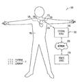
図1は、CRMシステム100のいくつかの部分、及び、システム100が利用される環境のいくつかの部分の実施形態の1つを例示したものである。CRMシステム100は、埋込可能型システム115と外部システム155とを含み、さらに埋込可能型システム115と外部システム155の間の双方向通信を可能にするテレメトリ・リンク145を備えている。埋込可能型システム115は、埋込可能型医用装置120とリード・システム108を備えている。埋込可能型医用装置120は体102内に移植され、リード・システム108を介して心臓105に結合されている。埋込可能型医用装置120の例には、制限するわけではないが、ペースメーカ、ペースメーカ/細動除去器、心臓再同期装置、心臓リモデリング制御装置、心臓モニタが含まれる。実施形態の1つでは、リード・システム108には、複数の心房と心室リードが含まれる。実施形態の1つでは、外部システム155はプログラマを含む。もう1つの実施形態では、外部システム155は患者管理システムであって、埋込可能型装置140に近接した外部装置150と比較的遠い位置にある遠隔装置170を含み、さらに、外部装置150と遠隔装置170をリンクする遠隔通信ネットワーク160を含む。患者管理システムによって、患者状況のモニタと治療の調整といった目的のため、遠隔位置から埋込可能型システム115にアクセスすることが可能になる。実施形態の1つでは、テレメトリリンク145は、誘導性テレメトリリンクである。ある代替実施形態では、遠隔通信リンク145は、遠距離電磁界無線周波数テレメトリリンクである。実施形態の1つでは、テレメトリリンク145によって、埋込可能型医用装置120から外部システム155へのデータ伝送が行われる。これには、例えば、埋込可能型医用装置120によって捕捉したリアルタイムの生理学的データを伝送すること、埋込可能型医用装置120によって捕捉され、それに記憶されている生理学的データを取り出すこと、埋込可能型医用装置120に記憶されている治療歴データを取り出すこと、埋込可能型医用装置120の動作状況(例えば、バッテリ状況及びリード・インピーダンス)を示すデータを取り出すことなどが含まれる。もう1つの実施形態では、テレメトリリンク145によって、外部システム155から埋込可能型医用装置120へのデータ伝送が行われる。これには、例えば、生理学的データを捕捉するように、埋込可能型医用装置120にプログラミングすることと、少なくとも1つの自己診断試験(装置の動作状況に関するような)を実施するように、埋込可能型医用装置120にプログラミングすることと、少なくとも1つの治療を行うように、埋込可能型医用装置120にプログラミングすることなどが含まれる。
FIG. 1 illustrates one embodiment of some portions of the
図2Aは、無線ECG検知を行う、埋込可能型医用装置220Aの回路のいくつかの部分に関する実施形態の1つを例示したブロック図である。埋込可能型医用装置220Aは、埋込可能型医用装置120のある特定の実施形態であり、数あるコンポーネントの中でも、心臓信号を検知するプログラマブル検知回路222を備えている。プログラマブル検知回路222は、電極210Aと210Bを介して心臓信号を検知する、1対の差動入力である検知入力223と検知入力224を備えている。電極210A、210Bは、体102内において体表面ECGに近似した信号を検知するように構成されており、そのために選択された位置に配置されている。実施形態の1つでは、プログラマブル検知回路222は、無線ECGの検知に適した周波数応答をするようにプログラム可能である。実施形態の1つでは、プログラマブル検知回路222は、無線ECGの検知に適した少なくとも1つの周波数応答をし、心臓内電位図の検知に適した別の周波数応答をするようにプログラム可能である。
FIG. 2A is a block diagram illustrating one embodiment of several portions of the circuitry of an implantable
図2Bは、無線ECG検知を行う、埋込可能型医用装置220Bの回路のいくつかの部分に関するもう1つの実施形態を例示したブロック図である。埋込可能型医用装置220Bは埋込可能型医用装置120の別の特定の実施形態であり、さらに、プログラマブル検知インターフェイス230を備えている。プログラマブル検知インターフェイス230は、複数の検知インターフェイス入力を備え、かつ検知入力223に接続された出力と検知入力224に接続されたもう1つの出力を備えている。検知インターフェイス入力は、電極210A、210Bを含む複数の電極をインターフェースに接続する。プログラマブル検知インターフェイス230によれば、複数の電極の任意の2つと検知入力223、224との選択的接続が可能になる。例えば、プログラマブル検知インターフェイス230は、ある期間中には、電極210Aを検知入力223に接続し、電極210Bを検知入力224に接続するようにプログラムされ、別の期間中には、電極210Mを検知入力223に接続し、電極210Nを検知入力224に接続するようにプログラムされる。一般に、電極210A、210B、210M、210Nは、それぞれ、無線ECG検知に用いるため、埋込可能型システム115において利用可能な複数の電極の任意の1つに相当する。プログラマブル検知インターフェイス230は、ある時には、第1の電極対をプログラマブル検知回路222に接続し、別の時には、第2の電極対をプログラマブル検知回路222に接続する等のプログラミングすることが可能である。埋込可能型医用装置220Bに、並列をなすプログラマブル検知回路222の複数ユニットのような、マルチチャネル検知回路が含まれる場合には、プログラマブル検知インターフェイス230は、それぞれ、1つの体表面ECGベクトルに近似した複数信号の同時検知ができるように、複数電極対を、それぞれ、1つの検知チャネルに接続するようにプログラム可能である。
FIG. 2B is a block diagram illustrating another embodiment of some portions of the circuitry of the implantable
埋込可能型医用装置220Bには、さらに、その動作を制御するプロセッサ232を備えている。プロセッサ232は、ECG捕捉コマンドを受信するコマンド受信器234を含み、心臓信号の検知を開始させるためのECG捕捉信号を発生する。埋込可能型医用装置220BにECG捕捉信号が存在する間中、心臓信号、すなわち、体表面ECGに近似した信号が検知される。プログラマブル検知回路222とプログラマブル検知インターフェイス230は、両方とも、ECG捕捉信号が生じると、体表面ECGに近似した信号を検知するようにプログラムされている。ECG捕捉コマンドは、外部システム155から、または、埋込可能型医用装置220B内から発生する。実施形態の1つでは、体表面ECGが必要になると、ユーザによって、ECG捕捉コマンドが埋込可能型医用装置220Bに伝送される。別の実施形態では、プロセッサ232は、所定の状態を検出し、所定の状態が検出されるとECG捕捉コマンドを発生する検出器を備えている。特定の実施形態の1つでは、検出器は、電位図から不整脈の発症を検出する不整脈検出器を含む。別の特定の実施形態では、検出器は、体の全身運動を検知する加速度計や毎分換気量を検知する呼吸センサのような活動センサを備えている。特定の実施形態の1つでは、運動中の体表面ECGに近似した信号を捕捉するため、検出器は、検知した活動レベルが所定のしきい値を超えると、ECG捕捉コマンドを発生する。こうして、運動中のECG捕捉が起動される。別の実施形態では、体表面ECGに近似した信号のモーション・アーチファクトが問題になると、活動レベルを利用して、その信号の捕捉が停止させる。特定の実施形態の1つでは、検出器は、所定の状態を検出すると、連続してECG捕捉コマンドを発生する。別の特定の実施形態では、検出器は、毎時、毎日、毎週、または、他の周期といった、組み込みスケジュールまたはユーザ・プログラマブル・スケジュールに基づいて、所定の状態を検出し、ECG捕捉コマンドを発生する。この実施形態の場合、プロセッサ232には、組み込みスケジュールまたはユーザ・プログラマブル・スケジュールに基づいて、所定の状態の検出を起動し、そのタイミングをとる検出タイマを備えている。
The implantable
図3A〜図3Fでは、電極210A−B(または210M−N)のさまざまな実施形態が、210AA−BA、210AB−BB、210AC−BC、210AD−BD、210AE−BE、210AF−BFとして表示されている。体表面ECGに近似した信号を検知するため、電極210Aが検知入力223に電気的に接続され、電極210Bが検知入力224に電気的に接続されているが、この場合、電極210A−Bは、電極対210AA−BA、210AB−BB、210AC−BC、210AD−BD、210AE−BE、210AF−BFの1つを含む。別の実施形態では、体表面ECGに近似した信号を検知するため、プログラマブル検知インターフェイス230が、電極210Aと検知入力223の間を電気的に接続し、電極210Bと検知入力224の間にもう1つの電気的接続を行うようにプログラムされるが、この場合、電極210A−Bは、電極対210AA−BA、210AB−BB、210AC−BC、210AD−BD、210AE−BE、210AF−BFの1つを含む。図3Gには、それぞれ、体表面ECGベクトルの1つに近似した複数信号を考慮した電極システムが例示されている。
In FIGS. 3A-3F, the various embodiments of
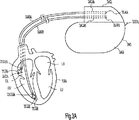
図3Aは、無線ECG検知を行う典型的な電極システムの1つを例示したものである。埋込可能型医用装置120の特定の実施形態の1つである埋込可能型医用装置320Aは、リード308A、308Bを含むが、これらに限定されないリード・システムを介して心臓105に電気的に接続されている。無線ECG検知に用いられる電極は、リード・システムのペーシング電極から選択される。
FIG. 3A illustrates one exemplary electrode system for performing wireless ECG detection. One particular embodiment of implantable
埋込可能型医用装置320Aは、その回路を収容する気密封止缶341を備えている。缶341に収容された回路は、プログラマブル検知回路222の少なくともいくつかの部分を備えている。缶341は外表面が体組織に接触させられる。缶341は、缶電極340のベースを含んでいるか、または、缶電極340のベースになる。缶341の外表面の少なくとも一部は、導電性材料から製作されている。実施形態の1つでは、缶341が缶電極340として用いられる。特定の実施形態の1つでは、缶電極340に、缶341の少なくとも1つの導電性部分を備えている。別の実施形態では、缶電極340は、缶341の外表面に組み込まれている。缶電極340は、非導電層を用いて、缶341の任意の導電性部分から電気的に絶縁される。特定の実施形態の1つでは、導体を含む気密密閉されたフィードスルーによって、缶電極340と缶341に収容された回路との電気的接続が施される。缶341には、ヘッダ342が取り付けられるが、これには、缶341に収容された回路への電気的アクセスを可能にするコネクタ343A−Bを備えている。
Implantable medical device 320A includes a hermetically sealed can 341 that houses the circuit. The circuit housed in the
図3Aに例示のように、リード・システムには、心房ペーシング・リード308Aと心室ペーシング・リード308Bを備えている。心房ペーシング・リード308Aは、近位端314Aと遠位端313Aを備えている。近位端314Aは、コネクタ343Aに接続されている。遠位端313Aには、先端電極312Aが配置されている。先端電極312Aから所定の距離をあけて、遠位端313Aの近くに、リング電極210AAが配置されている。心室ペーシング・リード308Bは、近位端314Bと遠位端313Bを備えている。近位端314Bはコネクタ343Bに接続されている。遠位端313Bには、先端電極312Bが配置されている。先端電極312Bから所定の距離をあけて、遠位端313Bの近くに、リング電極210BAが配置されている。図3Aに例示のように、特定の実施形態の1つでは、心房ペーシング・リード308AはRAリードであり、心室ペーシング・リード308BはRVリードである。別の特定の実施形態では、心房ペーシング・リード308AはRAリードであり、心室ペーシング・リード308BはLVリードである。
As illustrated in FIG. 3A, the lead system includes an
実施形態の1つでは、体表面ECGに近似した信号を検知するため、RAリードのリング電極(電極210AA)が、検知入力223に電気的に接続され、RV(またはLV)リードのリング電極(電極210BA)が、検知入力224に電気的に接続される。別の実施形態では、体表面ECGに近似した信号を検知するため、プログラマブル検知インターフェイス230が、RAリードのリング電極(電極210AA)と検知入力223の間に電気的接続を行い、RV(またはLV)リードのリング電極(電極210BA)と検知入力224の間にもう1つの電気的接続を設けるようにプログラムされる。
In one embodiment, the RA lead ring electrode (electrode 210AA) is electrically connected to the
図3Bは、無線ECG検知を行うための別の典型的な電極システムを例示したものである。埋込可能型医用装置120の別の特定の実施形態である埋込可能型医用装置320Bは、リード308Aと308Bを含むリード・システムを介して心臓105に電気的に接続されている。体表面ECGに近似した信号を検知するため、心室ペーシング・リード308Bのリング電極は、電極210ABとして利用され、缶電極340は電極210BBとして利用される。図3Bに例示のように、特定の実施形態の1つでは、心室ペーシング・リード308BはRVリードである。別の特定の実施形態では、心室ペーシング・リード308BはLVリードである。
FIG. 3B illustrates another exemplary electrode system for performing wireless ECG detection. Another particular embodiment of implantable
実施形態の1つでは、体表面ECGに近似した信号を検知するため、RV(またはLV)リードのリング電極(電極210AA)が検知入力223に電気的に接続され、缶電極340(電極210BA)が検知入力224に電気的に接続される。別の実施形態では、体表面ECGに近似した信号を検知するため、プログラマブル検知インターフェイス230が、RV(またはLV)リードのリング電極(電極210AA)と検知入力223の間に電気的接続を行い、缶電極340(電極210BA)と検知入力224の間にもう1つの電気的接続を設けるようにプログラムされる。
In one embodiment, the ring electrode (electrode 210AA) of the RV (or LV) lead is electrically connected to the
図3Cは、無線ECG検知を行うための別の典型的な電極システムを例示したものである。埋込可能型医用装置320Cは埋込可能型医用装置120の別の特定の実施形態である。電極210ACがヘッダ342に組み込まれている。特定の実施形態の1つでは、埋込可能型医用装置320Cは、毎分換気量を表すインピーダンス信号を検知する、呼吸センサとして機能するインピーダンス・センサを備えている。電極210ACは、インピーダンス・センサの中立電極である。缶電極340は電極210BCとして利用される。
FIG. 3C illustrates another exemplary electrode system for performing wireless ECG detection. Implantable medical device 320C is another specific embodiment of implantable
実施形態の1つでは、体表面ECGに近似した信号を検知するため、電極210AC(例えば、インピーダンス・センサの中立電極)が検知入力223に電気的に接続され、電極210BC(缶電極340)が検知入力224に電気的に接続される。別の実施形態では、体表面ECGに近似した信号を検知するため、プログラマブル検知インターフェイス230が、電極210AC(例えば、インピーダンス・センサの中立電極)と検知入力223の間に電気的接続を行い、電極210BC(缶電極340)と検知入力224の間にもう1つの電気的接続を設けるようにプログラムされる。
In one embodiment, electrode 210AC (eg, a neutral electrode of an impedance sensor) is electrically connected to sense
別の実施形態では、複数電極がヘッダ342に組み込まれる。電極のうち任意のものが、体表面ECGに近似した信号の検知専用とされるか、または、他の目的に利用される。こうした電極のうち任意のものは、電極210ACとして機能することが可能である。
In another embodiment, multiple electrodes are incorporated into the
図3Dは、無線ECG検知を行うための別の典型的な電極システムを例示したものである。埋込可能型医用装置320Dは埋込可能型医用装置120の別の特定の実施形態である。同心電極が、非導電層によって、缶341の導電性部分から絶縁されている。図3Dに示すように、同心電極対は内側電極210ADと外側電極210BDを備えている。内側電極210ADは円形状である。外側電極210BDはリング形状である。実施形態の1つでは、内側電極210ADの表面積は約15〜50mm2であり、外側電極210BDの表面積は約50〜150mm2である。特定の実施形態の1つでは、内側電極210ADの表面積は約31.7mm2であり、外側電極210BDの表面積は約87.1mm2である。実施形態の1つでは、導体を含む気密密閉されたフィードスルーによって、内側電極210ADと缶341に収容された回路との間に電気的接続が施され、導体を含むもう1つの気密密閉されたフィードスルーによって、外側電極210BDと缶341に収容された回路との間にもう1つの電気的接続が施される。別の実施形態では、2つの導体を含む気密密閉されたフィードスルーによって、内側電極210ADと外側電極210BDの両方について、缶341に収容された回路への電気的アクセスが行われる。
FIG. 3D illustrates another exemplary electrode system for performing wireless ECG detection. Implantable
実施形態の1つでは、体表面ECGに近似した信号を検知するため、内側電極210ADが検知入力223に電気的に接続され、外側電極210BDが検知入力224に電気的に接続される。別の実施形態では、体表面ECGに近似した信号を検知するため、プログラマブル検知インターフェイス230が、内側電極210ADと検知入力223との間に電気的接続を行い、外側電極210BDと検知入力224との間にもう1つの電気的接続を設けるようにプログラムされる。
In one embodiment, the inner electrode 210AD is electrically connected to the
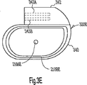
図3Eは、無線ECG検知を行うための別の典型的な電極システムを例示したものである。埋込可能型医用装置320Eは埋込可能型医用装置120の別の特定の実施形態である。1対の同心電極が、缶341の外表面に組み込まれる(取り付けられる)。同心電極は、非導電層を用いて、缶341の導電性部分から電気的に絶縁されている。図3Eに示すように、同心電極対は内側電極210AEと外側電極210BEを備えている。内側電極210AEは円形状である。外側電極210BEは缶341の輪郭に近似した形状である。実施形態の1つでは、内側電極210AEの表面積は約3〜12mm2であり、外側電極の表面積は約100〜250mm2である。特定の実施形態の1つでは、内側電極210AEの表面積は約7.9mm2であり、外側電極の表面積は約170mm2である。実施形態の1つでは、導体を含む気密密閉されたフィードスルーによって、内側電極210AEと缶341に収容された回路との間に電気的接続が施され、導体を含むもう1つの気密密閉されたフィードスルーによって、外側電極210BEと缶341に収容された回路との間にもう1つの電気的接続が施される。別の実施形態では、2つの導体を含む気密密閉されたフィードスルーによって、内側電極210AEと外側電極210BEの両方について、缶341に収容された回路への電気的アクセスが行われる。
FIG. 3E illustrates another exemplary electrode system for performing wireless ECG detection. Implantable
実施形態の1つでは、体表面ECGに近似した信号を検知するため、内側電極210AEが検知入力223に電気的に接続され、外側電極210BEが検知入力224に電気的に接続される。別の実施形態では、体表面ECGに近似した信号を検知するため、プログラマブル検知インターフェイス230が、内側電極210AEと検知入力223との間に電気的接続を行い、外側電極210BEと検知入力224との間にもう1つの電気的接続を設けるようにプログラムされる。
In one embodiment, the inner electrode 210AE is electrically connected to the
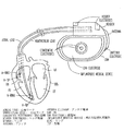
図3Fは、無線ECG検知を行うための別の典型的な電極システムを例示したものである。埋込可能型医用装置320Fは埋込可能型医用装置120の別の特定の実施形態である。埋込可能型医用装置320Fは無線周波テレメトリのためのアンテナ344を備えている。アンテナ344は、缶341に収容された回路に電気的に接続されている。実施形態の1つでは、図3Fに例示のように、アンテナ344が、ヘッダ342から突き出し、缶341の片側に沿って延びている。実施形態の1つでは、アンテナ344は、遠位部分がアンテナ電極210AFとして機能するため露出された金属導体を含んでいる。缶電極340は、電極210BFとして用いられる。
FIG. 3F illustrates another exemplary electrode system for performing wireless ECG detection. Implantable
実施形態の1つでは、体表面ECGに近似した信号を検知するため、アンテナ344/電極210AFが検知入力223に電気的に接続され、缶電極340が検知入力224に電気的に接続される。別の実施形態では、体表面ECGに近似した信号を検知するため、プログラマブル検知インターフェイス230が、アンテナ344/電極210AFと検知入力223との間に電気的接続を行い、缶電極340と検知入力224との間にもう1つの電気的接続を設けるようにプログラムされる。
In one embodiment, the
云うまでもないが、図3A〜図3Eを参照して論考の実施形態は、例示を意図したものであって、限定を意図したものではない。体表面ECGに近似しているか、さもなければ、診断及び/または治療のために役立つ情報を含んでいる信号が検知される限りにおいて、他の電極構成や選択を利用することも可能である。複数ECGベクトルが必要とされる各種実施形態では、マルチチャネル無線ECG検知のために、同時に、または、1つずつ、複数電極対が選択される。特定の実施形態の1つでは、標準的なマルチリード体表面ECG記録に近似するように、複数信号が検知される。別の特定の実施形態では、特定の診断に必要となる特定の情報に応じて、複数信号が検知される。それらの信号は、必ずしも、標準体表面ECGベクトルに近似するとは限らない。 It will be appreciated that the embodiments discussed with reference to FIGS. 3A-3E are intended to be illustrative and not limiting. Other electrode configurations and selections can be utilized as long as a signal is detected that approximates the body surface ECG or otherwise contains information useful for diagnosis and / or treatment. In various embodiments where multiple ECG vectors are required, multiple electrode pairs are selected simultaneously or one by one for multi-channel wireless ECG detection. In one particular embodiment, multiple signals are detected to approximate a standard multilead body surface ECG recording. In another specific embodiment, multiple signals are detected in response to specific information required for a specific diagnosis. These signals do not necessarily approximate the standard surface ECG vector.
図3Gは、こうした複数ベクトル無線ECG検知を可能にする典型的な電極システムを例示したものである。図3Gに例示のように、電極システムには、図3A〜図3Fを参照して上述した全ての電極を備えている。すなわち、電極システムは、心房リードの先端電極とリング電極(A−TIP及びA−RING)、1つ以上の心室リードの先端電極とリング電極(V−TIP及びV−RING)、埋込可能型医用装置の缶(缶電極)、埋込可能型医用装置のヘッダに組み込まれた1つ以上の電極(ヘッダ電極)、2つ以上の同心電極、アンテナ電極を備えている。実施形態の1つでは、体表面ECGに近似した信号を検知するため、プログラマブル検知インターフェイス230が、これらの電極の1つと検知入力223の間に電気的接続を行い、これらの電極と検知入力224との間にもう1つの電気的接続を設けるようにプログラムされる。換言すれば、プログラマブル検知インターフェイス230は、プログラマブル検知回路222と、埋込可能型システム115において利用可能な任意の2つの電極から選択された1対の電極との間を電極接続するようにプログラムされる。実施形態の1つでは、プログラマブル検知インターフェイス230は、複数信号(ベクトル)を得るため、プログラマブル検知回路222にいくつかの電極対を1つずつ接続するようにプログラムされる。別の実施形態では、プログラマブル検知インターフェイス230は、複数信号(ベクトル)を同時に得るため、いくつかの電極対を、それぞれ、(平列するプログラマブル検知回路222のマルチ回路のような)マルチチャネル検知回路のチャネルの1つに接続するようにプログラムされる。これらの実施形態において、1対または複数対の電極には、それぞれ、電極210AA−AF、電極210BA−210BF、埋込可能型システム115における任意の他の電極を含む、体表面ECGに近似した信号を検知するための任意の組み合わせの電極が含まれる。特定の実施形態の1つでは、埋込可能型医用装置には、無線ECG検知のため、2つの(第1及び第2の)ヘッダ電極と、缶電極を備えている。ECGベクトルは、(1)第1のヘッダ電極と第2のヘッダ電極の間、(2)第1のヘッダ電極と缶電極の間、(3)第2のヘッダ電極と缶電極の間で検知される。別の特定の実施形態では、埋込可能型医用装置は、無線ECG検知のため、ヘッダ電極、アンテナ電極、缶電極の1つを備えている。ECGベクトルは、(1)ヘッダ電極とアンテナ電極の間、(2)ヘッダ電極と缶電極の間、(3)アンテナ電極と缶電極の間で検知される。別の特定の実施形態では、埋込可能型医用装置は、無線ECG検知のため、2つの(第1及び第2の)ヘッダ電極と、アンテナ電極と、缶電極を備えている。ECGベクトルは、(1)第1のヘッダ電極と第2のヘッダ電極の間、(2)第1のヘッダ電極とアンテナ電極の間、(3)第1のヘッダ電極と缶電極の間、(4)第2のヘッダ電極とアンテナ電極の間、(5)第2のヘッダ電極と缶電極の間、(6)アンテナ電極と缶電極の間で検知される。可能性のある診断と他の医療上の必要性や考慮事項に基づいて、無線ECG検知のために任意の電極の組合せを必要とする他の特定の実施形態を用いることができる。
FIG. 3G illustrates an exemplary electrode system that enables such multi-vector wireless ECG detection. As illustrated in FIG. 3G, the electrode system includes all of the electrodes described above with reference to FIGS. 3A-3F. That is, the atrial lead tip and ring electrodes (A-TIP and A-RING), one or more ventricular lead tip and ring electrodes (V-TIP and V-RING), implantable It has a can (can electrode) of a medical device, one or more electrodes (header electrode) incorporated in a header of an implantable medical device, two or more concentric electrodes, and an antenna electrode. In one embodiment, the
図4は、プログラマブル検知回路422、プロセッサ232、埋込可能型テレメトリモジュール436、メモリ回路438を含む、埋込可能型医用装置120の回路の諸部分の実施形態の1つを示すブロック図である。
FIG. 4 is a block diagram illustrating one embodiment of portions of the circuitry of implantable
プログラマブル検知回路222の特定の実施形態であるプログラマブル検知回路422は、入力223、224、前置増幅回路425、デシメータ426、アナログ・ディジタル変換器(ADC)427、ディジタル帯域フィルタ428を含む。実施形態の1つでは、前記増幅回路425は、アナログ増幅器とアナログ・フィルタを含む。別の実施形態では、プログラマブル検知インターフェイス230に、アナログ・フィルタを備える。プログラマブル検知回路422の利得及び周波数応答は、前置増幅回路425とディジタル帯域フィルタ428の特性によって決まる。実施形態の1つでは、プログラマブル検知回路422の利得及び周波数応答は、それぞれ、プログラム可能である。利得には、少なくとも、体表面ECGに近似した信号の検知に適するように選択可能な利得と、心臓内電位図の検知に適するように選択可能な利得が得られるようにプログラム可能な利得が含まれる。周波数応答には、少なくとも、体表面ECGに近似した信号の検知に適するように選択可能な体表面ECG通過帯域と、心臓内電位図の検知に適するように選択可能な心臓内電位図通過帯域が得られるようにプログラム可能な通過帯域が含まれる。各通過帯域は、低カットオフ周波数と高カットオフ周波数によって決まる。低カットオフ周波数と高カットオフ周波数の少なくとも一方はプログラム可能である。低カットオフ周波数及び/または高カットオフ周波数は、前置増幅回路425とディジタル帯域フィルタ428の一方または両方にプログラミングすることによって、プログラミングすることが可能である。体表面ECG通過帯域には、体表面ECGに近似した検知信号に、関連する低周波成分を備えているか否かを確認するために選択された低カットオフ周波数を備えている。実施形態の1つでは、体表面ECG通過帯域の低カットオフ周波数は4Hz以下にプログラム可能である。もう1つの実施形態では、体表面ECG通過帯域の低カットオフ周波数は0.5Hz以下にプログラム可能である。実施形態の1つでは、プログラマブル検知回路422の低カットオフ周波数は、0.1Hz〜30Hzの範囲でプログラム可能であり、プログラマブル検知回路422の高カットオフ周波数は、30Hz〜150Hzの範囲でプログラム可能である。通過帯域が体表面ECG通過帯域にプログラムされると、低カットオフ周波数は0.1Hz〜4Hzの値にプログラムされ、高カットオフ周波数は30Hz〜100Hzの値にプログラムされる。通過帯域が心臓内電位図通過帯域にプログラムされると、低カットオフ周波数は10Hz〜30Hzの値にプログラムされ、高カットオフ周波数は60Hz〜150Hzの値にプログラムされる。
埋込可能型テレメトリモジュール436は、テレメトリリンク145を介して、体表面ECGに近似した検知信号を外部システム155に伝送する。実施形態の1つでは、コマンド受信器234が、埋込可能型テレメトリモジュール436を介して外部システム155からECG捕捉コマンドを受信する。
The
メモリ回路438は、体表面ECGに近似した検知信号を記憶するためのECG記憶装置を備えている。実施形態の1つでは、埋込可能型医用装置120は、ECG捕捉コマンドを受信すると、体表面ECGに近似した信号を検知して、ほぼリアルタイムで、検知信号を外部システム155に伝送する。別の実施形態では、埋込可能型医用装置120は、ECG捕捉コマンドを受信すると、体表面ECGに近似した信号を検知して、検知信号をECG記憶装置に記憶し、後で伝送されるようにする。
The
図5は、電極210A、210B、埋込可能型医用装置120、外部システム155を含むCRMシステム100の諸部分を示すブロック図である。外部システム155には、数あるコンポーネントの中でも、外部テレメトリモジュール552、ユーザ入力装置554、ディスプレイ556を備えている。外部テレメトリモジュール552は、テレメトリリンク145を介して、埋込可能型医用装置120から体表面ECGに近似した信号を受信し、埋込可能型医用装置120にECG捕捉コマンドを送信する。ユーザ入力装置554は、ユーザが入力したECG捕捉コマンドを受信する。ディスプレイ556は、体表面ECGに近似した信号を視覚的に表示する。実施形態の1つでは、体表面ECGに近似した信号は、埋込可能型医用装置120によって検知されると、ほぼリアルタイムで表示される。別の実施形態では、体表面ECGに近似した信号は、埋込可能型医用装置120のメモリ回路438のECG記憶装置から取り出されると、表示される。
FIG. 5 is a block diagram illustrating portions of the
実施形態の1つでは、外部システム155には、プログラマを備えている。別の実施形態では、外部システム155は、図1に例示のように、外部装置150、ネットワーク160、遠隔装置170を含む患者管理システムである。特定の実施形態の1つでは、遠隔装置170に、ユーザ入力554とディスプレイ556を備えている。これによって、ユーザは、遠隔施設からの患者のECGをリアルタイムで検分するか、あるいは、記憶することが可能になる。
In one embodiment, the
図6は、上述のCRMシステム100のようなシステムを利用する無線ECG検知方法の実施形態の1つを例示したフローチャートである。この方法では、埋込可能型医用装置を利用することにより、皮膚接触電極、及び、電極とECG記録装置を接続するワイヤ/ケーブルの必要をなくして、体表面ECGの代わりとなる信号の検知が可能になる。
FIG. 6 is a flowchart illustrating one embodiment of a wireless ECG detection method utilizing a system such as the
600において、ECG捕捉コマンドが、埋込可能型医用装置によって受信される。実施形態の1つでは、ECG捕捉コマンドは、テレメトリにより外部装置から受信する。別の実施形態では、1つ以上の所定の心臓状態が埋込可能型医用装置によって検出され、その1つ以上の所定の心臓状態の検出に応答して、埋込可能型医用装置内でECG捕捉コマンドが発生する。 At 600, an ECG capture command is received by the implantable medical device. In one embodiment, the ECG capture command is received from an external device by telemetry. In another embodiment, one or more predetermined heart conditions are detected by the implantable medical device, and in response to detecting the one or more predetermined heart conditions, an ECG in the implantable medical device. A capture command occurs.
610において、埋込可能型医用装置の検知回路は、ECG捕捉コマンドに応答して、体表面ECGをモニタするようにプログラムされる。これには、体表面ECGのモニタに適したカットオフ周波数になるように、帯域濾波回路にプログラミングするステップが含まれる。実施形態の1つでは、低カットオフ周波数は、約0.1Hz〜10Hzの値にプログラムされ、高カットオフ周波数は、約30Hz〜100Hzの値になるようにプログラムされる。最大量の情報が求められる、特定の実施形態の1つでは、低カットオフ周波数は約0.1Hzにプログラムされ、高カットオフ周波数は約100Hzにプログラムされる。雑音レベルを最小限に抑えなければならない別の特定の実施形態では、低カットオフ周波数は約0.5Hzにプログラムされ、高カットオフ周波数は約50Hz以下にプログラムされる。 At 610, the implantable medical device sensing circuitry is programmed to monitor the body surface ECG in response to the ECG capture command. This includes programming the bandpass filter to have a cutoff frequency suitable for monitoring the body surface ECG. In one embodiment, the low cutoff frequency is programmed to a value of about 0.1 Hz to 10 Hz and the high cutoff frequency is programmed to a value of about 30 Hz to 100 Hz. In one particular embodiment where the maximum amount of information is desired, the low cutoff frequency is programmed to about 0.1 Hz and the high cutoff frequency is programmed to about 100 Hz. In another specific embodiment where the noise level must be minimized, the low cutoff frequency is programmed to about 0.5 Hz and the high cutoff frequency is programmed to about 50 Hz or less.
620において、埋込可能型医用装置の検知回路は、ECG捕捉コマンドに応答して、1対の電極を検知回路に接続するようにプログラムされる。この電極対は、体表面ECGに近似した心臓信号の検知に適している。実施形態の1つでは、検知インターフェイスが、検知回路とRAペーシング・リードのリング電極との間に電気的接続を行い、検知回路とRVペーシング・リードのリング電極との間にもう1つの電気的接続を設けるようにプログラムされる。別の実施形態では、検知インターフェイスは、検知回路とRVペーシング・リードのリング電極の間に電気的接続を行い、検知回路と埋込可能型医用装置のハウジングの間にもう1つの電気的接続を設けるようにプログラムされる。別の実施形態では、検知インターフェイスは、検知回路と、埋込可能型医用装置に含まれるインピーダンス・センサの中立電極との間に電気的接続を行い、検知回路と埋込可能型医用装置のハウジングの間にもう1つの電気的接続を設けるようにプログラムされる。別の実施形態では、検知インターフェイスは、検知回路と、埋込可能型医用装置のハウジングに組み込まれた1対の同心電極との間を接続するようにプログラムされる。特定の実施形態の1つでは、同心電極に、内側電極と外側電極が含まれており、検知インターフェイスは、検知回路と内側電極の間に電気的接続を行い、検知回路と外側電極の間にもう1つの電気的接続を設けるようにプログラムされる。 At 620, the sensing circuit of the implantable medical device is programmed to connect a pair of electrodes to the sensing circuit in response to an ECG capture command. This electrode pair is suitable for detecting a cardiac signal approximate to the body surface ECG. In one embodiment, the sensing interface provides an electrical connection between the sensing circuit and the ring electrode of the RA pacing lead, and another electrical connection between the sensing circuit and the ring electrode of the RV pacing lead. Programmed to provide a connection. In another embodiment, the sensing interface provides an electrical connection between the sensing circuit and the ring electrode of the RV pacing lead, and another electrical connection between the sensing circuit and the housing of the implantable medical device. Programmed to provide. In another embodiment, the sensing interface provides an electrical connection between the sensing circuit and a neutral electrode of an impedance sensor included in the implantable medical device, the housing of the sensing circuit and the implantable medical device. Are programmed to provide another electrical connection between them. In another embodiment, the sensing interface is programmed to connect between sensing circuitry and a pair of concentric electrodes incorporated in the housing of the implantable medical device. In one particular embodiment, the concentric electrodes include an inner electrode and an outer electrode, and the sensing interface provides an electrical connection between the sensing circuit and the inner electrode, and between the sensing circuit and the outer electrode. Programmed to provide another electrical connection.
検知回路と検知インターフェイスのプログラミングが済むと、630において、体表面ECGに近似した心臓信号が検知される。実施形態の1つでは、検知した心臓信号が外部装置に送信され、ほぼリアルタイムで表示される。別の実施形態の場合、検知した心臓信号は、埋込可能型医用装置に記憶され、後で、外部装置に送られて、表示される。 After programming the sensing circuit and sensing interface, at 630, a cardiac signal approximating the body surface ECG is detected. In one embodiment, the detected heart signal is transmitted to an external device and displayed in near real time. In another embodiment, sensed cardiac signals are stored in an implantable medical device and later sent to an external device for display.
実施形態の1つでは、体表面ECGに近似した検知心臓信号が、P波、QRSオンセット、R波、QRSオフセット、T波を含むが、これに限定されない、基準点に関連した測定値に関して表示される。実施形態の1つでは、体表面ECGに近似した検知心臓信号が、内因性心臓脱分極を表わす検知マーカ、ペーシング・パルス供給を表わすペース・マーカ、毎分換気量信号、心音、及び、呼吸と他の機械的事象を表わすマーカといった、埋込可能型医用装置によって捕捉される信号及び/またはこれら捕捉信号から導き出される信号と同時に表示される。実施形態の1つでは、体表面ECGに近似した心臓信号の検知によって、ペーシング及び/または細動除去治療のための検知方式全体が強化される。特定の実施形態の1つでは、体表面ECGに近似した心臓信号によって、電位図から検出される事象の独立した検証が可能になる。別の特定の実施形態では、電位図の検知システムが機能障害の場合に、体表面ECGに近似した心臓信号が、その電位図の代わりになる。患者管理システムが用いられる実施形態の1つでは、体表面ECGに近似した心臓信号が、夜間心房細動または無呼吸といった概日性事象に関して、リアルタイムで表示される。特定の実施形態の1つでは、これらの事象は、傾向把握のため記憶される。この傾向把握を利用して、信号形態の経時シフトが求められ、表示される。 In one embodiment, the sensed cardiac signal approximated to the body surface ECG is related to measurements related to reference points, including but not limited to P-waves, QRS onsets, R-waves, QRS offsets, T-waves. Is displayed. In one embodiment, the detected cardiac signal approximated to the body surface ECG includes a sensing marker representing intrinsic cardiac depolarization, a pace marker representing pacing pulse delivery, a minute ventilation signal, a heart sound, and respiration. Displayed simultaneously with signals captured by and / or derived from the implantable medical device, such as markers representing other mechanical events. In one embodiment, sensing the cardiac signal close to the body surface ECG enhances the overall sensing scheme for pacing and / or defibrillation therapy. In one particular embodiment, cardiac signals that approximate the body surface ECG allow for independent verification of events detected from the electrogram. In another specific embodiment, when the electrogram sensing system is dysfunctional, a cardiac signal approximating the body surface ECG is substituted for the electrogram. In one embodiment in which a patient management system is used, cardiac signals that approximate the body surface ECG are displayed in real time for circadian events such as nocturnal atrial fibrillation or apnea. In one particular embodiment, these events are stored for trending. By using this tendency grasp, a shift of the signal form with time is obtained and displayed.
もちろん、上記詳細な説明は、説明を意図したものであって、制限を意図したものではない。例えば、上述の無線ECG検知システムは、体表面ECGに近似した信号の検知に適した検知回路と電極を含む、任意の埋込可能型医用装置で実施することが可能である。上記説明を読み、理解すれば、当業者には、本明細書において論考するシステム・コンポーネントの可能性のある任意の置換を含む、他の実施形態が明らかになるであろう。本発明の範囲は、従って、付属の請求の範囲、並びに、こうした請求の範囲が権利を付与される同等物の全範囲に準拠して判定すべきである。 Of course, the above detailed description is intended to be illustrative and not limiting. For example, the wireless ECG detection system described above can be implemented with any implantable medical device that includes detection circuitry and electrodes suitable for detection of signals that approximate the body surface ECG. Upon reading and understanding the above description, other embodiments will become apparent to those skilled in the art, including any possible permutations of system components discussed herein. The scope of the invention should, therefore, be determined with reference to the appended claims, along with the full scope of equivalents to which such claims are entitled.
100 CRMシステム、108 リード・システム、115 埋込可能型システム、120 埋込可能型医用装置、145 テレメトリリンク、150 外部装置、155 外部システム、160 遠隔通信ネットワーク、170 遠隔装置 100 CRM system, 108 lead system, 115 implantable system, 120 implantable medical device, 145 telemetry link, 150 external device, 155 external system, 160 telecommunications network, 170 remote device
Claims (56)
体表面心電図(ECG)に近似した心臓信号を検知するために選択可能な第1の電極および第2の電極を少なくとも含む複数の埋込可能な電極と、
埋込可能な医用装置と
を含み、
前記埋込可能な医用装置は、
ECG捕捉コマンドに応答して、体表面ECGに近似した前記心臓信号を検知するようにプログラムされた検知回路と、
前記検知回路の動作を制御するように構成されたプロセッサであって、前記ECG捕捉コマンドを受信するように構成されたコマンド受信器を含むプロセッサと、
前記ECG捕捉コマンドに応答して、前記体表面ECGに近似した前記心臓信号を検知するための第1の電気的接続および第2の電気的接続を少なくとも提供するようにプログラムされたプログラム可能な検知インターフェースと
を含み、
前記検知回路は、
前記体表面ECGに近似した前記心臓信号を検知するように構成された一対の差動入力である第1の検知入力および第2の検知入力と、
前記体表面ECGに近似した前記心臓信号を検知するために選択可能な体表面ECG利得および心臓内電位図を検知するために選択可能な電位図利得に対して少なくともプログラム可能な利得と、
前記体表面ECGに近似した前記心臓信号を検知するために選択可能な体表面ECG通過帯域および心臓内電位図を検知するために選択可能な心臓内電位図通過帯域に対して少なくともプログラム可能な周波数応答特性と
を含み、
前記第1の電気的接続は、前記第1の電極を前記第1の検知入力に接続し、前記第2の電気的接続は、前記第2の電極を前記第2の検知入力に接続する、システム。 A cardiac rhythm management system,
A plurality of implantable electrodes including at least a first electrode and a second electrode can be selected to sense cardiac signals that approximate body surface electrocardiogram (ECG),
And implantable medical devices
Including
The implantable medical device,
In response to the ECG acquisition command, and the programmed sensing circuit to sense the cardiac signal that approximates the body surface ECG,
And a processor configured to control operation of the sensing circuit, and a processor comprising a configuration commands receiver to receive the ECG acquisition command,
In response to the ECG acquisition command, the first electrical connection and a second electrical connection of the programmable it is programmed to provide at least sensing for sensing the cardiac signal approximate to the body surface ECG interface and
Including
The detection circuit includes:
A first sensing input and a second sensing input that are a pair of differential inputs configured to sense the cardiac signal approximated to the body surface ECG;
At least programmable gain for selectable electrogram gain to detect the surface ECG gain and intracardiac electrograms selectable to sense the cardiac signal approximating the surface ECG,
At least programmable frequency for selectable intracardiac electrogram passband to detect the body surface ECG passband and intracardiac electrograms selectable to sense the cardiac signal approximate to the body surface ECG Response characteristics and
Including
The first electrical connection connects the first electrode to the first sensing input, and the second electrical connection connects the second electrode to the second sensing input; system.
第2の近位端および第2の遠位端を有する第2のペーシング・リードと
をさらに含み、
前記第1の電極は、前記第1の遠位端またはその近くにあり、前記第2の電極は、前記第2の遠位端またはその近くにある、請求項1〜7のいずれかに記載のシステム。A first pacing lead including a first proximal end and a first distal end;
Further comprising a second pacing lead having a second proximal end and a second distal end,
Said first electrode, said there first distal end or near, the second electrode, the certain second distal end or near the, according to any one of claims 1 to 7 System.
前記第2のペーシング・リードは、心室ペーシング・リードである、請求項8に記載のシステム。The first pacing lead is an atrial pacing lead;
Said second pacing lead, a ventricular pacing lead system of claim 8.
前記第2のペーシング・リードは、第2の先端電極および第2のリング電極を少なくとも含み、前記第2の先端電極は、前記第2の遠位端に配置され、前記第2のリング電極は、前記第2の遠位端の近くに、前記第2の先端電極から所定の距離をあけて配置され、
前記第1の電極は、前記第1のリング電極であり、前記第2の電極は、前記第2のリング電極である、請求項8〜11のいずれかに記載のシステム。Said first pacing lead comprises at least a first tip electrode and the first ring electrode, the first tip electrode is disposed on the first distal end, said first ring electrode , Disposed near the first distal end, at a predetermined distance from the first tip electrode,
Said second pacing lead comprises at least a second tip electrode and a second ring electrode, the second tip electrode is disposed on the second distal end, said second ring electrode , Disposed near the second distal end and at a predetermined distance from the second tip electrode;
Said first electrode, said a first ring electrode, said second electrode, said a second ring electrode system according to any of claims 8-11.
前記検知回路の少なくともいくつかの部分を含む回路を収容する気密封止缶と、
前記缶の少なくとも一部、および、前記缶に組み込まれ、前記缶から電気的に絶縁された電極のうちの一方を含む缶電極と
をさらに含み、
前記第1の電極は、前記ペーシング・リードの前記遠位端またはその近くにあり、前記第2の電極は、缶電極である、請求項1〜7のいずれかに記載のシステム。 A pacing lead including a proximal end and a distal end;
A hermetically sealed can containing a circuit including at least some portions of the sensing circuit;
And at least a part of the can , and a can electrode including one of the electrodes incorporated into the can and electrically insulated from the can , and
Said first electrode is located at the distal end or near the pacing lead, the second electrode is a can electrode, as claimed in any one of claims 1 to 7 System.
前記ヘッダに組み込まれる電極である少なくとも1つのヘッダ電極と、
前記缶の少なくとも一部、および、前記缶に組み込まれ、前記缶から電気的に絶縁された電極のうちの一方を含む缶電極と
を含み、
前記第1の電極は、前記少なくとも1つのヘッダ電極であり、前記第2の電極は、前記缶電極である、請求項17に記載のシステム。The implantable medical device,
At least one header electrode which is an electrode incorporated in the header;
A can electrode comprising at least a portion of the can and one of the electrodes incorporated into the can and electrically insulated from the can;
Including
The first electrode, the at least one header electrodes, said second electrode, said a can electrode system according to claim 17.
前記患者管理システムは、
テレメトリ法によって前記埋込可能な医用装置に通信可能に結合された外部装置と、
前記外部装置に結合されたネットワークと、
前記ネットワークに結合された遠隔装置と
を含む、請求項29または30に記載のシステム。The external system includes a patient management system ,
The patient management system includes :
An external device communicatively coupled to the implantable medical device by telemetry method,
A network coupled to the external device;
A remote device coupled to the network ;
The system according to claim 29 or 30 , comprising:
前記検知回路の少なくともいくつかの部分を含む埋込可能回路を収容する気密封止缶であって、前記缶は、体組織に接触させられる外表面を有する、気密封止缶と、
前記缶の前記外表面に組み込まれ、内側電極および外側電極を含む少なくとも2つの同心電極と
を含み、
前記内側電極は、前記第1の検知入力に結合され、前記外側電極は、前記第2の検知入力に結合される、埋込可能な医用装置。A sensing circuit programmable to provide a frequency response suitable for detecting a body surface electrocardiogram (ECG) , a first sensing input and a second sensing being a pair of differential inputs for sensing a cardiac signal A sensing circuit including an input;
A hermetically sealed can containing an implantable circuit including at least some portions of the sensing circuit, the can having an outer surface that is brought into contact with body tissue;
At least two concentric electrodes incorporated into the outer surface of the can and including an inner electrode and an outer electrode;
Including
The inner electrode is coupled to the first sensing input, wherein the outer electrode is coupled to the second sense input, implantable medical device.
体表面心電図(ECG)ベクトルに近似したそれぞれの心臓信号を検知するように構成された複数の埋込可能な電極と、
埋込可能な医用装置と
を含み、
前記埋込可能な医用装置は、
前記心臓信号の同時検知を提供する複数の検知チャネルを含む検知回路と、
前記検知回路の動作を制御するプロセッサであって、ECG捕捉コマンドを受信するコマンド受信器を含むプロセッサと、
前記複数の検知チャネルのうちの1つと前記複数の埋込可能な電極から選択される2つの電極との間に、それぞれ、複数の対をなす電気的接続を提供するプログラム可能な検知インターフェイスと
を含み、
前記複数の埋込可能な電極は、前記埋込可能な医用装置に組み込まれている、システム。 A cardiac rhythm management system,
A plurality of implantable electrodes adapted to detect the respective cardiac signals approximates to the body surface electrocardiogram (ECG) vector,
And a implantable medical device,
The implantable medical device,
A sensing circuit including a plurality of sensing channels to provide simultaneous sensing of the cardiac signal;
A processor for controlling the operation of the detection circuit, and a processor including a command receiver for receiving an ECG acquisition command,
Between the two electrodes selected from one of the plurality of implantable electrodes of the plurality of sensing channels, respectively, and a programmable sensing interface to provide an electrical connection forming a plurality of pairs Including
Wherein the plurality of implantable electrodes, Ru Tei incorporated into the implantable medical device, the system.
前記検知回路の少なくともいくつかの部分を含む埋込可能回路を収容する気密封止缶と、
前記缶の少なくとも一部、および、前記缶に組み込まれ、前記缶から電気的に絶縁された電極のうちの一方を含む缶電極と
を含む、請求項44に記載のシステム。The implantable medical device,
A hermetically sealed can containing an implantable circuit including at least some portions of the sensing circuit;
At least a portion of the can, and, incorporated in the can, and a can electrode comprising one of electrically isolated electrodes from the can, the system according to claim 44.
Applications Claiming Priority (3)
| Application Number | Priority Date | Filing Date | Title |
|---|---|---|---|
| US10/795,126 | 2004-03-05 | ||
| US10/795,126 US7299086B2 (en) | 2004-03-05 | 2004-03-05 | Wireless ECG in implantable devices |
| PCT/US2005/006984 WO2005089643A1 (en) | 2004-03-05 | 2005-03-03 | Wireless ecg in implantable devices |
Publications (3)
| Publication Number | Publication Date |
|---|---|
| JP2007527294A JP2007527294A (en) | 2007-09-27 |
| JP2007527294A5 JP2007527294A5 (en) | 2008-04-17 |
| JP4733686B2 true JP4733686B2 (en) | 2011-07-27 |
Family
ID=34912437
Family Applications (1)
| Application Number | Title | Priority Date | Filing Date |
|---|---|---|---|
| JP2007501996A Expired - Fee Related JP4733686B2 (en) | 2004-03-05 | 2005-03-03 | Wireless ECG in implantable devices |
Country Status (4)
| Country | Link |
|---|---|
| US (5) | US7299086B2 (en) |
| EP (1) | EP1729637A1 (en) |
| JP (1) | JP4733686B2 (en) |
| WO (1) | WO2005089643A1 (en) |
Families Citing this family (173)
| Publication number | Priority date | Publication date | Assignee | Title |
|---|---|---|---|---|
| US6493579B1 (en) | 1999-08-20 | 2002-12-10 | Cardiac Pacemakers, Inc. | System and method for detection enhancement programming |
| US6766189B2 (en) * | 2001-03-30 | 2004-07-20 | Cardiac Pacemakers, Inc. | Method and apparatus for predicting acute response to cardiac resynchronization therapy |
| US6993389B2 (en) | 2001-03-30 | 2006-01-31 | Cardiac Pacemakers, Inc. | Identifying heart failure patients suitable for resynchronization therapy using QRS complex width from an intracardiac electrogram |
| US6705999B2 (en) * | 2001-03-30 | 2004-03-16 | Guidant Corporation | Method and apparatus for determining the coronary sinus vein branch accessed by a coronary sinus lead |
| US7101339B2 (en) | 2002-12-13 | 2006-09-05 | Cardiac Pacemakers, Inc. | Respiration signal measurement apparatus, systems, and methods |
| US7200440B2 (en) | 2003-07-02 | 2007-04-03 | Cardiac Pacemakers, Inc. | Cardiac cycle synchronized sampling of impedance signal |
| US7684861B2 (en) * | 2003-11-13 | 2010-03-23 | Cardiac Pacemakers, Inc. | Implantable cardiac monitor upgradeable to pacemaker or cardiac resynchronization device |
| US20060247693A1 (en) | 2005-04-28 | 2006-11-02 | Yanting Dong | Non-captured intrinsic discrimination in cardiac pacing response classification |
| US8521284B2 (en) | 2003-12-12 | 2013-08-27 | Cardiac Pacemakers, Inc. | Cardiac response classification using multisite sensing and pacing |
| US7774064B2 (en) | 2003-12-12 | 2010-08-10 | Cardiac Pacemakers, Inc. | Cardiac response classification using retriggerable classification windows |
| US7783353B2 (en) | 2003-12-24 | 2010-08-24 | Cardiac Pacemakers, Inc. | Automatic neural stimulation modulation based on activity and circadian rhythm |
| US7668594B2 (en) | 2005-08-19 | 2010-02-23 | Cardiac Pacemakers, Inc. | Method and apparatus for delivering chronic and post-ischemia cardiac therapies |
| US8126560B2 (en) | 2003-12-24 | 2012-02-28 | Cardiac Pacemakers, Inc. | Stimulation lead for stimulating the baroreceptors in the pulmonary artery |
| US8024050B2 (en) | 2003-12-24 | 2011-09-20 | Cardiac Pacemakers, Inc. | Lead for stimulating the baroreceptors in the pulmonary artery |
| US7706884B2 (en) | 2003-12-24 | 2010-04-27 | Cardiac Pacemakers, Inc. | Baroreflex stimulation synchronized to circadian rhythm |
| US7869881B2 (en) | 2003-12-24 | 2011-01-11 | Cardiac Pacemakers, Inc. | Baroreflex stimulator with integrated pressure sensor |
| US7277754B2 (en) * | 2003-12-24 | 2007-10-02 | Cardiac Pacemakers, Inc. | Method and system for removing pacing artifacts from subcutaneous electrocardiograms |
| US7460906B2 (en) | 2003-12-24 | 2008-12-02 | Cardiac Pacemakers, Inc. | Baroreflex stimulation to treat acute myocardial infarction |
| US7486991B2 (en) | 2003-12-24 | 2009-02-03 | Cardiac Pacemakers, Inc. | Baroreflex modulation to gradually decrease blood pressure |
| US9020595B2 (en) | 2003-12-24 | 2015-04-28 | Cardiac Pacemakers, Inc. | Baroreflex activation therapy with conditional shut off |
| US7873413B2 (en) * | 2006-07-24 | 2011-01-18 | Cardiac Pacemakers, Inc. | Closed loop neural stimulation synchronized to cardiac cycles |
| US7840263B2 (en) | 2004-02-27 | 2010-11-23 | Cardiac Pacemakers, Inc. | Method and apparatus for device controlled gene expression |
| US7299086B2 (en) | 2004-03-05 | 2007-11-20 | Cardiac Pacemakers, Inc. | Wireless ECG in implantable devices |
| FR2868323B1 (en) * | 2004-04-05 | 2006-06-02 | Ela Medical Sa | ACTIVE IMPLANTABLE MEDICAL DEVICE WITH DIAGNOSTIC MEANS FOR RESPIRATORY DISORDERS, WITH IMPROVED DETECTION OF ARTIFACT BREATHING CYCLES |
| US7706866B2 (en) | 2004-06-24 | 2010-04-27 | Cardiac Pacemakers, Inc. | Automatic orientation determination for ECG measurements using multiple electrodes |
| US7751890B2 (en) * | 2004-07-14 | 2010-07-06 | Cardiac Pacemakers, Inc. | Self-diagnostic method and system for implantable cardiac device |
| US7917196B2 (en) | 2005-05-09 | 2011-03-29 | Cardiac Pacemakers, Inc. | Arrhythmia discrimination using electrocardiograms sensed from multiple implanted electrodes |
| US7797036B2 (en) | 2004-11-30 | 2010-09-14 | Cardiac Pacemakers, Inc. | Cardiac activation sequence monitoring for ischemia detection |
| US7890159B2 (en) | 2004-09-30 | 2011-02-15 | Cardiac Pacemakers, Inc. | Cardiac activation sequence monitoring and tracking |
| US7457664B2 (en) | 2005-05-09 | 2008-11-25 | Cardiac Pacemakers, Inc. | Closed loop cardiac resynchronization therapy using cardiac activation sequence information |
| US7509170B2 (en) | 2005-05-09 | 2009-03-24 | Cardiac Pacemakers, Inc. | Automatic capture verification using electrocardiograms sensed from multiple implanted electrodes |
| US7805185B2 (en) | 2005-05-09 | 2010-09-28 | Cardiac Pacemakers, In. | Posture monitoring using cardiac activation sequences |
| US8175705B2 (en) * | 2004-10-12 | 2012-05-08 | Cardiac Pacemakers, Inc. | System and method for sustained baroreflex stimulation |
| US7212849B2 (en) | 2004-10-28 | 2007-05-01 | Cardiac Pacemakers, Inc. | Methods and apparatuses for arrhythmia detection and classification using wireless ECG |
| US7328063B2 (en) * | 2004-11-30 | 2008-02-05 | Cardiac Pacemakers, Inc. | Method and apparatus for arrhythmia classification using atrial signal mapping |
| US20060116596A1 (en) * | 2004-12-01 | 2006-06-01 | Xiaohong Zhou | Method and apparatus for detection and monitoring of T-wave alternans |
| US8118741B2 (en) | 2004-12-20 | 2012-02-21 | Hypo-Safe A/X | Method and apparatus for prediction and warning of hypoglycaemic attack |
| US7295874B2 (en) * | 2005-01-06 | 2007-11-13 | Cardiac Pacemakers, Inc. | Intermittent stress augmentation pacing for cardioprotective effect |
| US7283864B2 (en) * | 2005-02-10 | 2007-10-16 | Cardiac Pacemakers, Inc. | Method and apparatus for identifying patients with wide QRS complexes |
| US8473049B2 (en) | 2005-05-25 | 2013-06-25 | Cardiac Pacemakers, Inc. | Implantable neural stimulator with mode switching |
| US7493161B2 (en) | 2005-05-10 | 2009-02-17 | Cardiac Pacemakers, Inc. | System and method to deliver therapy in presence of another therapy |
| US7542800B2 (en) | 2005-04-05 | 2009-06-02 | Cardiac Pacemakers, Inc. | Method and apparatus for synchronizing neural stimulation to cardiac cycles |
| US8406876B2 (en) | 2005-04-05 | 2013-03-26 | Cardiac Pacemakers, Inc. | Closed loop neural stimulation synchronized to cardiac cycles |
| US20060241715A1 (en) * | 2005-04-22 | 2006-10-26 | Cardiac Pacemakers, Inc. | Electrode for a pulse generator and method therefor |
| US7962208B2 (en) | 2005-04-25 | 2011-06-14 | Cardiac Pacemakers, Inc. | Method and apparatus for pacing during revascularization |
| US7392086B2 (en) | 2005-04-26 | 2008-06-24 | Cardiac Pacemakers, Inc. | Implantable cardiac device and method for reduced phrenic nerve stimulation |
| US20060259088A1 (en) * | 2005-05-13 | 2006-11-16 | Pastore Joseph M | Method and apparatus for delivering pacing pulses using a coronary stent |
| US7894896B2 (en) * | 2005-05-13 | 2011-02-22 | Cardiac Pacemakers, Inc. | Method and apparatus for initiating and delivering cardiac protection pacing |
| US7917210B2 (en) | 2005-05-13 | 2011-03-29 | Cardiac Pacemakers, Inc. | Method and apparatus for cardiac protection pacing |
| US7922669B2 (en) | 2005-06-08 | 2011-04-12 | Cardiac Pacemakers, Inc. | Ischemia detection using a heart sound sensor |
| US7848792B2 (en) * | 2005-07-05 | 2010-12-07 | Ela Medical S.A.S. | Detection of apneae and hypopneae in an active implantable medical device |
| US8784336B2 (en) | 2005-08-24 | 2014-07-22 | C. R. Bard, Inc. | Stylet apparatuses and methods of manufacture |
| US7774057B2 (en) | 2005-09-06 | 2010-08-10 | Cardiac Pacemakers, Inc. | Method and apparatus for device controlled gene expression for cardiac protection |
| US7616990B2 (en) * | 2005-10-24 | 2009-11-10 | Cardiac Pacemakers, Inc. | Implantable and rechargeable neural stimulator |
| US8108034B2 (en) | 2005-11-28 | 2012-01-31 | Cardiac Pacemakers, Inc. | Systems and methods for valvular regurgitation detection |
| US7885710B2 (en) * | 2005-12-23 | 2011-02-08 | Cardiac Pacemakers, Inc. | Method and apparatus for tissue protection against ischemia using remote conditioning |
| US20070156190A1 (en) * | 2005-12-30 | 2007-07-05 | Can Cinbis | Subcutaneous ICD with motion artifact noise suppression |
| US7567836B2 (en) * | 2006-01-30 | 2009-07-28 | Cardiac Pacemakers, Inc. | ECG signal power vector detection of ischemia or infarction |
| US8050759B2 (en) * | 2006-01-31 | 2011-11-01 | Medtronic, Inc. | Subcutaneous ICD with separate cardiac rhythm sensor |
| US20070190028A1 (en) * | 2006-02-13 | 2007-08-16 | Jihong Qu | Method and apparatus for heat or electromagnetic control of gene expression |
| US7689286B2 (en) * | 2006-05-02 | 2010-03-30 | Cardiac Pacemakers, Inc. | Myocardium conditioning using myocardial and parasympathetic stimulation |
| US7702383B2 (en) * | 2006-05-04 | 2010-04-20 | Cardiac Pacemakers, Inc. | Methodology for automated signal morphology analysis in implantable electrotherapy and diagnostic systems |
| US8000780B2 (en) | 2006-06-27 | 2011-08-16 | Cardiac Pacemakers, Inc. | Detection of myocardial ischemia from the time sequence of implanted sensor measurements |
| US8527048B2 (en) | 2006-06-29 | 2013-09-03 | Cardiac Pacemakers, Inc. | Local and non-local sensing for cardiac pacing |
| US7580741B2 (en) | 2006-08-18 | 2009-08-25 | Cardiac Pacemakers, Inc. | Method and device for determination of arrhythmia rate zone thresholds using a probability function |
| US8209013B2 (en) | 2006-09-14 | 2012-06-26 | Cardiac Pacemakers, Inc. | Therapeutic electrical stimulation that avoids undesirable activation |
| US8712507B2 (en) | 2006-09-14 | 2014-04-29 | Cardiac Pacemakers, Inc. | Systems and methods for arranging and labeling cardiac episodes |
| FR2906123A1 (en) * | 2006-09-25 | 2008-03-28 | Ela Medical Soc Par Actions Si | METHOD FOR RECONSTRUCTING A SURFACE ELECTROCARDIOGRAM FROM A ENDOCAVITARY ELECTROGRAM |
| US7794407B2 (en) | 2006-10-23 | 2010-09-14 | Bard Access Systems, Inc. | Method of locating the tip of a central venous catheter |
| US8388546B2 (en) | 2006-10-23 | 2013-03-05 | Bard Access Systems, Inc. | Method of locating the tip of a central venous catheter |
| US7941208B2 (en) | 2006-11-29 | 2011-05-10 | Cardiac Pacemakers, Inc. | Therapy delivery for identified tachyarrhythmia episode types |
| US8014863B2 (en) | 2007-01-19 | 2011-09-06 | Cardiac Pacemakers, Inc. | Heart attack or ischemia detector |
| US7736319B2 (en) | 2007-01-19 | 2010-06-15 | Cardiac Pacemakers, Inc. | Ischemia detection using heart sound timing |
| US8523771B2 (en) * | 2007-02-12 | 2013-09-03 | Cardiac Pacemakers, Inc. | Cardiovascular pressure annotations and logbook |
| US8615296B2 (en) | 2007-03-06 | 2013-12-24 | Cardiac Pacemakers, Inc. | Method and apparatus for closed-loop intermittent cardiac stress augmentation pacing |
| US20080234591A1 (en) * | 2007-03-20 | 2008-09-25 | Scinicariello Anthony P | Methods and apparatus for patient notification of physiologic events and device function |
| US8055339B2 (en) | 2007-04-11 | 2011-11-08 | Cardiac Pacemakers, Inc. | Reverse pacing-mode switch |
| US7873414B2 (en) * | 2007-04-17 | 2011-01-18 | Cardiac Pacemakers, Inc. | Patient characteristic based adaptive anti-tachy pacing programming |
| US8265736B2 (en) | 2007-08-07 | 2012-09-11 | Cardiac Pacemakers, Inc. | Method and apparatus to perform electrode combination selection |
| US9037239B2 (en) | 2007-08-07 | 2015-05-19 | Cardiac Pacemakers, Inc. | Method and apparatus to perform electrode combination selection |
| JP5119334B2 (en) | 2007-10-12 | 2013-01-16 | カーディアック ペースメイカーズ, インコーポレイテッド | Decompensation detection based on heart failure comorbidity |
| US10524691B2 (en) | 2007-11-26 | 2020-01-07 | C. R. Bard, Inc. | Needle assembly including an aligned magnetic element |
| US9649048B2 (en) | 2007-11-26 | 2017-05-16 | C. R. Bard, Inc. | Systems and methods for breaching a sterile field for intravascular placement of a catheter |
| US10751509B2 (en) | 2007-11-26 | 2020-08-25 | C. R. Bard, Inc. | Iconic representations for guidance of an indwelling medical device |
| CN103750858B (en) | 2007-11-26 | 2017-04-12 | C·R·巴德股份有限公司 | Integrated system for intravascular placement of a catheter |
| US10449330B2 (en) | 2007-11-26 | 2019-10-22 | C. R. Bard, Inc. | Magnetic element-equipped needle assemblies |
| US8849382B2 (en) | 2007-11-26 | 2014-09-30 | C. R. Bard, Inc. | Apparatus and display methods relating to intravascular placement of a catheter |
| US9521961B2 (en) | 2007-11-26 | 2016-12-20 | C. R. Bard, Inc. | Systems and methods for guiding a medical instrument |
| US8781555B2 (en) | 2007-11-26 | 2014-07-15 | C. R. Bard, Inc. | System for placement of a catheter including a signal-generating stylet |
| US8548586B2 (en) | 2008-01-29 | 2013-10-01 | Cardiac Pacemakers, Inc. | Configurable intermittent pacing therapy |
| WO2009097527A1 (en) * | 2008-01-30 | 2009-08-06 | Transoma Medical, Inc. | Minimally invasive physiologic parameter recorder and introducer system |
| US8649866B2 (en) | 2008-02-14 | 2014-02-11 | Cardiac Pacemakers, Inc. | Method and apparatus for phrenic stimulation detection |
| US8140155B2 (en) | 2008-03-11 | 2012-03-20 | Cardiac Pacemakers, Inc. | Intermittent pacing therapy delivery statistics |
| WO2009117086A2 (en) | 2008-03-17 | 2009-09-24 | Cardiac Pacemakers, Inc. | Deactivation of intermittent pacing therapy |
| US8332049B2 (en) * | 2008-03-31 | 2012-12-11 | Boston Scientific Neuromodulation Corporation | Implantable multi-lead electric stimulation system and methods of making and using |
| US7917226B2 (en) * | 2008-04-23 | 2011-03-29 | Enteromedics Inc. | Antenna arrangements for implantable therapy device |
| US20090275998A1 (en) * | 2008-04-30 | 2009-11-05 | Medtronic, Inc. | Extra-cardiac implantable device with fusion pacing capability |
| US20090275999A1 (en) * | 2008-04-30 | 2009-11-05 | Burnes John E | Extra-cardiac implantable device with fusion pacing capability |
| US8457738B2 (en) | 2008-06-19 | 2013-06-04 | Cardiac Pacemakers, Inc. | Pacing catheter for access to multiple vessels |
| US9037235B2 (en) | 2008-06-19 | 2015-05-19 | Cardiac Pacemakers, Inc. | Pacing catheter with expandable distal end |
| US9409012B2 (en) | 2008-06-19 | 2016-08-09 | Cardiac Pacemakers, Inc. | Pacemaker integrated with vascular intervention catheter |
| US8244352B2 (en) | 2008-06-19 | 2012-08-14 | Cardiac Pacemakers, Inc. | Pacing catheter releasing conductive liquid |
| US8639357B2 (en) | 2008-06-19 | 2014-01-28 | Cardiac Pacemakers, Inc. | Pacing catheter with stent electrode |
| WO2010022370A1 (en) | 2008-08-22 | 2010-02-25 | C.R. Bard, Inc. | Catheter assembly including ecg sensor and magnetic assemblies |
| EP2349467B1 (en) | 2008-10-06 | 2017-08-23 | Cardiac Pacemakers, Inc. | Dynamic cardiac resynchronization therapy by tracking intrinsic conduction |
| US8437833B2 (en) | 2008-10-07 | 2013-05-07 | Bard Access Systems, Inc. | Percutaneous magnetic gastrostomy |
| DE102008043480A1 (en) * | 2008-11-05 | 2010-05-06 | Biotronik Crm Patent Ag | Single-chamber cardiac stimulator |
| US9655518B2 (en) | 2009-03-27 | 2017-05-23 | Braemar Manufacturing, Llc | Ambulatory and centralized processing of a physiological signal |
| WO2010132203A1 (en) | 2009-05-15 | 2010-11-18 | Cardiac Pacemakers, Inc. | Pacing system with safety control during mode transition |
| US8958873B2 (en) | 2009-05-28 | 2015-02-17 | Cardiac Pacemakers, Inc. | Method and apparatus for safe and efficient delivery of cardiac stress augmentation pacing |
| EP2440122B1 (en) | 2009-06-12 | 2019-08-14 | Bard Access Systems, Inc. | Apparatus, computer-based data processing algorithm and computer storage medium for positioning an endovascular device in or near the heart |
| US9532724B2 (en) | 2009-06-12 | 2017-01-03 | Bard Access Systems, Inc. | Apparatus and method for catheter navigation using endovascular energy mapping |
| US9445734B2 (en) | 2009-06-12 | 2016-09-20 | Bard Access Systems, Inc. | Devices and methods for endovascular electrography |
| AU2010273546B2 (en) | 2009-07-15 | 2013-08-29 | Cardiac Pacemakers, Inc. | Physiological vibration detection in an implanted medical device |
| WO2011008748A2 (en) | 2009-07-15 | 2011-01-20 | Cardiac Pacemakers, Inc. | Remote pace detection in an implantable medical device |
| US8285373B2 (en) * | 2009-07-15 | 2012-10-09 | Cardiac Pacemakers, Inc. | Remote sensing in an implantable medical device |
| US20110054934A1 (en) * | 2009-08-31 | 2011-03-03 | General Electric Company, A New York Corporation | Patient initiated emergency response coordinator systems, apparatus, articles of manufacture, and methods |
| US8812104B2 (en) | 2009-09-23 | 2014-08-19 | Cardiac Pacemakers, Inc. | Method and apparatus for automated control of pacing post-conditioning |
| EP2482719A4 (en) * | 2009-09-29 | 2016-03-09 | Bard Inc C R | Stylets for use with apparatus for intravascular placement of a catheter |
| US8412326B2 (en) | 2009-10-30 | 2013-04-02 | Cardiac Pacemakers, Inc. | Pacemaker with vagal surge monitoring and response |
| EP2509683B1 (en) | 2009-12-08 | 2017-08-23 | Cardiac Pacemakers, Inc. | Concurrent therapy detection in implantable medical devices |
| ES2811107T3 (en) | 2010-02-02 | 2021-03-10 | Bard Inc C R | Apparatus and method for catheter conduction and tip localization |
| EP2575611B1 (en) | 2010-05-28 | 2021-03-03 | C. R. Bard, Inc. | Apparatus for use with needle insertion guidance system |
| CN103037762B (en) | 2010-05-28 | 2016-07-13 | C·R·巴德股份有限公司 | For inserting, with pin, the device that guiding system is used together |
| WO2012013212A1 (en) | 2010-07-30 | 2012-02-02 | Md Start Sa | Implantable electrode device, in particular for sensing an intracardiac electrogram |
| WO2012013360A1 (en) | 2010-07-30 | 2012-02-02 | Md Start Sa | Implantable electrode device, in particular for sensing an intracardiac electrogram |
| CN103442632A (en) | 2010-08-20 | 2013-12-11 | C·R·巴德股份有限公司 | Reconfirmation of ECG-assisted catheter tip placement |
| US8801693B2 (en) | 2010-10-29 | 2014-08-12 | C. R. Bard, Inc. | Bioimpedance-assisted placement of a medical device |
| US9420959B2 (en) | 2010-12-15 | 2016-08-23 | Cardiac Pacemakers, Inc. | Detecting heart failure by monitoring the time sequence of physiological changes |
| US9986918B2 (en) | 2011-03-14 | 2018-06-05 | Cardiac Pacemakers, Inc. | Systems and methods to indicate heart failure co-morbidity |
| KR20140061995A (en) | 2011-04-15 | 2014-05-22 | 인포바이오닉, 인크. | Remote data monitoring and collection system with multi-tiered analysis |
| US8812102B2 (en) | 2011-05-23 | 2014-08-19 | Cardiac Pacemakers, Inc. | Sensor response delay for hemodynamic stability detection during arrhythmia |
| US9713432B2 (en) | 2011-05-31 | 2017-07-25 | Cardiac Pacemakers, Inc. | Wide QRS detector |
| RU2609203C2 (en) | 2011-07-06 | 2017-01-30 | Си.Ар. Бард, Инк. | Determination and calibration of needle length for needle guidance system |
| US9161775B1 (en) | 2012-05-08 | 2015-10-20 | Greatbatch Ltd. | Tunneling tool for deliberate placement of an ILR |
| US9186513B2 (en) | 2013-03-07 | 2015-11-17 | Medtronic, Inc. | Subcutaneous cardiac monitoring devices, systems and methods |
| CN106068141B (en) | 2014-01-10 | 2019-05-14 | 心脏起搏器股份公司 | System and method for detecting cardiac arrhythmia |
| US10449361B2 (en) | 2014-01-10 | 2019-10-22 | Cardiac Pacemakers, Inc. | Systems and methods for treating cardiac arrhythmias |
| US9424020B2 (en) | 2014-01-13 | 2016-08-23 | Carefusion 303, Inc. | Remote flashing during infusion |
| US9839372B2 (en) | 2014-02-06 | 2017-12-12 | C. R. Bard, Inc. | Systems and methods for guidance and placement of an intravascular device |
| US10463866B2 (en) | 2014-07-11 | 2019-11-05 | Cardiac Pacemakers, Inc. | Systems and methods for treating cardiac arrhythmias |
| US10973584B2 (en) | 2015-01-19 | 2021-04-13 | Bard Access Systems, Inc. | Device and method for vascular access |
| WO2016126613A1 (en) | 2015-02-06 | 2016-08-11 | Cardiac Pacemakers, Inc. | Systems and methods for treating cardiac arrhythmias |
| US10052489B2 (en) | 2015-03-23 | 2018-08-21 | Greatbatch Ltd. | Apparatus and method for implanting an implantable device |
| US10271795B2 (en) | 2015-06-12 | 2019-04-30 | C. R. Bard, Inc. | Systems and methods for confirmation of prior catheter tip placement |
| US10349890B2 (en) | 2015-06-26 | 2019-07-16 | C. R. Bard, Inc. | Connector interface for ECG-based catheter positioning system |
| US11000207B2 (en) | 2016-01-29 | 2021-05-11 | C. R. Bard, Inc. | Multiple coil system for tracking a medical device |
| US9968274B2 (en) | 2016-04-29 | 2018-05-15 | Infobionic, Inc. | Systems and methods for processing ECG data |
| USD794807S1 (en) | 2016-04-29 | 2017-08-15 | Infobionic, Inc. | Health monitoring device with a display |
| USD794805S1 (en) | 2016-04-29 | 2017-08-15 | Infobionic, Inc. | Health monitoring device with a button |
| USD794806S1 (en) | 2016-04-29 | 2017-08-15 | Infobionic, Inc. | Health monitoring device |
| EP3512409A1 (en) | 2016-09-16 | 2019-07-24 | Boston Scientific Neuromodulation Corporation | System for pain management using heart sounds |
| US10758737B2 (en) | 2016-09-21 | 2020-09-01 | Cardiac Pacemakers, Inc. | Using sensor data from an intracardially implanted medical device to influence operation of an extracardially implantable cardioverter |
| EP3519037B1 (en) | 2016-09-27 | 2020-07-29 | Boston Scientific Neuromodulation Corporation | Systems for closed-loop pain management |
| US10750994B2 (en) | 2016-09-27 | 2020-08-25 | Boston Scientific Neuromodulation Corporation | Method and apparatus for pain management using objective pain measure |
| WO2018080887A1 (en) | 2016-10-25 | 2018-05-03 | Boston Scientific Neuromodulation Corporation | System for pain management using baroreflex sensitivity |
| US10631776B2 (en) | 2017-01-11 | 2020-04-28 | Boston Scientific Neuromodulation Corporation | Pain management based on respiration-mediated heart rates |
| US10729905B2 (en) | 2017-01-11 | 2020-08-04 | Boston Scientific Neuromodulation Corporation | Pain management based on muscle tension measurements |
| US10926091B2 (en) | 2017-01-11 | 2021-02-23 | Boston Scientific Neuromodulation Corporation | Pain management based on emotional expression measurements |
| US10675469B2 (en) | 2017-01-11 | 2020-06-09 | Boston Scientific Neuromodulation Corporation | Pain management based on brain activity monitoring |
| US10631777B2 (en) | 2017-01-11 | 2020-04-28 | Boston Scientific Neuromodulation Corporation | Pain management based on functional measurements |
| US11089997B2 (en) | 2017-01-11 | 2021-08-17 | Boston Scientific Neuromodulation Corporation | Patient-specific calibration of pain quantification |
| US10960210B2 (en) | 2017-02-10 | 2021-03-30 | Boston Scientific Neuromodulation Corporation | Method and apparatus for pain management with sleep detection |
| US10987517B2 (en) * | 2017-03-15 | 2021-04-27 | Medtronic, Inc. | Detection of noise signals in cardiac signals |
| EP3936185A1 (en) | 2017-07-18 | 2022-01-12 | Boston Scientific Neuromodulation Corporation | Sensor-based pain management systems and methods |
| CA3236972A1 (en) * | 2017-07-19 | 2019-01-24 | Endotronix, Inc. | Physiological monitoring system |
| US11419539B2 (en) | 2017-12-22 | 2022-08-23 | Regents Of The University Of Minnesota | QRS onset and offset times and cycle selection using anterior and posterior electrode signals |
| JP7176292B2 (en) * | 2018-08-21 | 2022-11-22 | オムロンヘルスケア株式会社 | Electrocardiograph |
| EP3852622B1 (en) | 2018-10-16 | 2025-04-02 | Bard Access Systems, Inc. | Safety-equipped connection systems and methods thereof for establishing electrical connections |
| IT201900025204A1 (en) | 2019-12-23 | 2021-06-23 | Praxe Srl | Optimized wireless electrocardiograph |
| US12023503B2 (en) | 2020-07-30 | 2024-07-02 | Medtronic, Inc. | ECG belt systems to interoperate with IMDs |
| US11813464B2 (en) | 2020-07-31 | 2023-11-14 | Medtronic, Inc. | Cardiac conduction system evaluation |
| US12280260B2 (en) | 2020-12-02 | 2025-04-22 | Medtronic, Inc. | Evaluation and adjustment of left bundle branch (LBB) pacing therapy |
Family Cites Families (88)
| Publication number | Priority date | Publication date | Assignee | Title |
|---|---|---|---|---|
| US4333470A (en) | 1980-04-07 | 1982-06-08 | Medtronic, Inc. | Output pulse artifact rejection in demand pacemakers |
| USRE32378E (en) | 1980-04-07 | 1987-03-24 | Medtronic, Inc. | Output pulse artifact rejection in demand pacemakers and sensing circuits employed in conjunction therewith |
| US4539999A (en) | 1983-07-22 | 1985-09-10 | Datascope Corp. | Method and device for subtracting a pacer signal from an ECG signal |
| US4585004A (en) | 1984-06-01 | 1986-04-29 | Cardiac Control Systems, Inc. | Heart pacing and intracardiac electrogram monitoring system and associated method |
| US4662382A (en) | 1985-01-16 | 1987-05-05 | Intermedics, Inc. | Pacemaker lead with enhanced sensitivity |
| EP0308536B2 (en) | 1987-09-24 | 1999-06-23 | Pacesetter, Inc. | Pacemaker having programmable configuration |
| US5040533A (en) * | 1989-12-29 | 1991-08-20 | Medical Engineering And Development Institute Incorporated | Implantable cardiovascular treatment device container for sensing a physiological parameter |
| US5113869A (en) | 1990-08-21 | 1992-05-19 | Telectronics Pacing Systems, Inc. | Implantable ambulatory electrocardiogram monitor |
| US5127401A (en) | 1990-11-09 | 1992-07-07 | Medtronic, Inc. | Method of and apparatus for multi-vector pacing artifact detection |
| US6638963B1 (en) * | 1990-12-04 | 2003-10-28 | Oregon Health And Science University | Methods for treating circadian rhythm disorders |
| EP0578748B1 (en) | 1991-04-05 | 1996-05-01 | Medtronic, Inc. | Subcutaneous multi-electrode sensing system |
| JP2764660B2 (en) | 1991-05-17 | 1998-06-11 | 信越化学工業株式会社 | Polymer scale adhesion inhibitor and method for preventing adhesion of polymer scale |
| WO1993008872A1 (en) | 1991-10-31 | 1993-05-13 | Medtronic, Inc. | Implantable medical device with flexible hardware platform |
| US5439481A (en) | 1992-02-26 | 1995-08-08 | Angeion Corporation | Semi-automatic atrial and ventricular cardioverter defibrillator |
| DE69319641T2 (en) | 1992-03-09 | 1999-02-18 | Angeion Corp., Plymouth, Minn. | Detection of tachycardia and cardiac fibrillation |
| US5324310A (en) | 1992-07-01 | 1994-06-28 | Medtronic, Inc. | Cardiac pacemaker with auto-capture function |
| US5265602A (en) | 1992-07-13 | 1993-11-30 | Medtronic, Inc. | Ring-to-ring cardiac electrogram pacemaker |
| US5456692A (en) | 1993-09-03 | 1995-10-10 | Pacesetter, Inc. | System and method for noninvasively altering the function of an implanted pacemaker |
| US5503160A (en) | 1993-10-12 | 1996-04-02 | Hewlett-Packard Company | Dynamic filter for real-time artifact removal from waveforms |
| US5379775A (en) | 1993-10-15 | 1995-01-10 | Medtronic, Inc. | Low amplitude pacing artifact detection apparatus and method using isolation amplifier to minimize distortion |
| US5448997A (en) | 1993-10-15 | 1995-09-12 | Medtronic, Inc. | Heart pacing pulse detection system |
| US5500008A (en) | 1994-03-29 | 1996-03-19 | Ventritex, Inc. | Method and apparatus for delivering defibrillation shocks with improved effectiveness |
| US6256313B1 (en) * | 1995-01-11 | 2001-07-03 | Sony Corporation | Triplet architecture in a multi-port bridge for a local area network |
| US5711305A (en) | 1995-02-17 | 1998-01-27 | Ep Technologies, Inc. | Systems and methods for acquiring endocardially or epicardially paced electrocardiograms |
| US5630425A (en) | 1995-02-17 | 1997-05-20 | Ep Technologies, Inc. | Systems and methods for adaptive filtering artifacts from composite signals |
| US5882352A (en) | 1995-05-25 | 1999-03-16 | Pacesetter, Inc. | Automatic adjustment of detection rate threshold in an implantable antitachycardia therapy device |
| SE9504258D0 (en) * | 1995-11-28 | 1995-11-28 | Pacesetter Ab | Device and method for generating a synthesized ECG |
| US5776168A (en) | 1996-04-03 | 1998-07-07 | Medtronic, Inc. | EGM recording system for implantable medical device |
| US5725559A (en) | 1996-05-16 | 1998-03-10 | Intermedics Inc. | Programmably upgradable implantable medical device |
| US6157859A (en) | 1996-05-16 | 2000-12-05 | Sulzer Intermedics, Inc. | Upgradable implantable medical device with post-shock pacing and redraw functions |
| US6496715B1 (en) | 1996-07-11 | 2002-12-17 | Medtronic, Inc. | System and method for non-invasive determination of optimal orientation of an implantable sensing device |
| US6134463A (en) * | 1997-03-31 | 2000-10-17 | Cordis Webster, Inc. | Electrophysiology catheter with a bullseye electrode |
| US5978707A (en) | 1997-04-30 | 1999-11-02 | Cardiac Pacemakers, Inc. | Apparatus and method for treating ventricular tachyarrhythmias |
| US5843138A (en) | 1997-07-09 | 1998-12-01 | Vitatron Medical, B.V. | Pacemaker system with enhanced programmable modification capacity |
| US5935081A (en) | 1998-01-20 | 1999-08-10 | Cardiac Pacemakers, Inc. | Long term monitoring of acceleration signals for optimization of pacing therapy |
| US6076015A (en) | 1998-02-27 | 2000-06-13 | Cardiac Pacemakers, Inc. | Rate adaptive cardiac rhythm management device using transthoracic impedance |
| US6088618A (en) | 1998-07-07 | 2000-07-11 | Vitatron Medical, B.V. | Pacemaker system and method for providing manual display concurrent with pacemaker software modification |
| US6141584A (en) | 1998-09-30 | 2000-10-31 | Agilent Technologies, Inc. | Defibrillator with wireless communications |
| US6169918B1 (en) | 1998-10-28 | 2001-01-02 | Cardiac Pacemakers, Inc. | Cardiac rhythm management system with cross-chamber soft blanking |
| US6201993B1 (en) | 1998-12-09 | 2001-03-13 | Medtronic, Inc. | Medical device telemetry receiver having improved noise discrimination |
| US6223078B1 (en) | 1999-03-12 | 2001-04-24 | Cardiac Pacemakers, Inc. | Discrimination of supraventricular tachycardia and ventricular tachycardia events |
| US6312388B1 (en) | 1999-03-12 | 2001-11-06 | Cardiac Pacemakers, Inc. | Method and system for verifying the integrity of normal sinus rhythm templates |
| US6230059B1 (en) | 1999-03-17 | 2001-05-08 | Medtronic, Inc. | Implantable monitor |
| US6179865B1 (en) | 1999-04-01 | 2001-01-30 | Cardiac Pacemakers, Inc. | Cross chamber interval correlation |
| US6334071B1 (en) * | 1999-06-07 | 2001-12-25 | Pacesetter, Inc. | Minute volume pacemakers that require only a single distal electrode |
| US6449503B1 (en) | 1999-07-14 | 2002-09-10 | Cardiac Pacemakers, Inc. | Classification of supraventricular and ventricular cardiac rhythms using cross channel timing algorithm |
| US6493579B1 (en) | 1999-08-20 | 2002-12-10 | Cardiac Pacemakers, Inc. | System and method for detection enhancement programming |
| US6418340B1 (en) * | 1999-08-20 | 2002-07-09 | Cardiac Pacemakers, Inc. | Method and system for identifying and displaying groups of cardiac arrhythmic episodes |
| US6480733B1 (en) | 1999-11-10 | 2002-11-12 | Pacesetter, Inc. | Method for monitoring heart failure |
| US6456871B1 (en) | 1999-12-01 | 2002-09-24 | Cardiac Pacemakers, Inc. | System and method of classifying tachyarrhythmia episodes as associated or disassociated |
| US6636963B1 (en) | 1999-12-30 | 2003-10-21 | Cardiac Pacemakers, Inc. | Quick starting for microprocessor-based system by retrieving a target state memory image and a target state data structure from an image storage medium |
| US6477404B1 (en) | 2000-03-01 | 2002-11-05 | Cardiac Pacemakers, Inc. | System and method for detection of pacing pulses within ECG signals |
| US6522925B1 (en) | 2000-05-13 | 2003-02-18 | Cardiac Pacemakers, Inc. | System and method for detection enhancement programming |
| US6522914B1 (en) | 2000-07-14 | 2003-02-18 | Cardiac Pacemakers, Inc. | Method and apparatuses for monitoring hemodynamic activities using an intracardiac impedance-derived parameter |
| US6512940B1 (en) | 2000-10-31 | 2003-01-28 | Medtronic, Inc. | Subcutaneous spiral electrode for sensing electrical signals of the heart |
| US6505067B1 (en) | 2000-11-22 | 2003-01-07 | Medtronic, Inc. | System and method for deriving a virtual ECG or EGM signal |
| US6745068B2 (en) | 2000-11-28 | 2004-06-01 | Medtronic, Inc. | Automated template generation algorithm for implantable device |
| US6574510B2 (en) * | 2000-11-30 | 2003-06-03 | Cardiac Pacemakers, Inc. | Telemetry apparatus and method for an implantable medical device |
| US6589187B1 (en) | 2000-12-08 | 2003-07-08 | Medtronic, Inc. | Prioritized dynamic memory allocation of arrhythmia episode detail collection |
| US6564106B2 (en) | 2000-12-13 | 2003-05-13 | Medtronic, Inc. | Thin film electrodes for sensing cardiac depolarization signals |
| US6904315B2 (en) | 2000-12-14 | 2005-06-07 | Medtronic, Inc. | Atrial aware VVI: a method for atrial synchronous ventricular (VDD/R) pacing using the subcutaneous electrode array and a standard pacing lead |
| US6622045B2 (en) * | 2001-03-29 | 2003-09-16 | Pacesetter, Inc. | System and method for remote programming of implantable cardiac stimulation devices |
| US6628988B2 (en) * | 2001-04-27 | 2003-09-30 | Cardiac Pacemakers, Inc. | Apparatus and method for reversal of myocardial remodeling with electrical stimulation |
| AU2002303488A1 (en) | 2001-05-03 | 2002-11-18 | Quetzal Biomedical, Inc. | Method and apparatus for determining spatial relation of multiple implantable electrodes |
| US6526313B2 (en) | 2001-06-05 | 2003-02-25 | Cardiac Pacemakers, Inc. | System and method for classifying cardiac depolarization complexes with multi-dimensional correlation |
| US7050851B2 (en) | 2001-06-29 | 2006-05-23 | Medtronic, Inc. | Implantable cardioverter/defibrillator with housing electrode and lead detection and switching circuitry |
| US6792307B1 (en) | 2001-09-12 | 2004-09-14 | Pacesetter, Inc. | Implantable cardiac stimulation system and method for measuring atrioventricular conduction and adjusting atrioventricular hysteresis |
| US6810283B2 (en) | 2001-09-13 | 2004-10-26 | Medtronic, Inc. | Multiple templates for filtering of far field R-waves |
| US6658283B1 (en) | 2001-09-25 | 2003-12-02 | Pacesetter, Inc. | Implantable cardiac stimulation device, system and method which provides an electrogram signal having the appearance of a surface electrocardiogram |
| US7027861B2 (en) | 2001-10-09 | 2006-04-11 | Medtronic, Inc. | Method and apparatus for affecting atrial defibrillation with bi-atrial pacing |
| US6760615B2 (en) | 2001-10-31 | 2004-07-06 | Medtronic, Inc. | Method and apparatus for discriminating between tachyarrhythmias |
| US6909916B2 (en) | 2001-12-20 | 2005-06-21 | Cardiac Pacemakers, Inc. | Cardiac rhythm management system with arrhythmia classification and electrode selection |
| US6889079B2 (en) | 2002-04-12 | 2005-05-03 | Cardiac Pacemakers, Inc. | Method and system for characterizing supraventricular rhythm during cardiac pacing |
| US7212857B2 (en) | 2002-05-01 | 2007-05-01 | Pacesetter, Inc. | Implantable cardiac device for restoring inter-chamber synchrony and method |
| US7031764B2 (en) | 2002-11-08 | 2006-04-18 | Cardiac Pacemakers, Inc. | Cardiac rhythm management systems and methods using multiple morphology templates for discriminating between rhythms |
| US7101339B2 (en) | 2002-12-13 | 2006-09-05 | Cardiac Pacemakers, Inc. | Respiration signal measurement apparatus, systems, and methods |
| US7191004B2 (en) | 2002-12-31 | 2007-03-13 | Cardiac Pacemakers, Inc. | Capture verification using an evoked response reference |
| US20040230229A1 (en) | 2003-04-11 | 2004-11-18 | Lovett Eric G. | Hybrid transthoracic/intrathoracic cardiac stimulation devices and methods |
| US20040215240A1 (en) | 2003-04-11 | 2004-10-28 | Lovett Eric G. | Reconfigurable subcutaneous cardiac device |
| US7177685B2 (en) | 2003-07-11 | 2007-02-13 | Cardiac Pacemakers, Inc. | Classifying tachyarrhythmia using time interval between ventricular depolarization and mitral valve closure |
| US7684861B2 (en) * | 2003-11-13 | 2010-03-23 | Cardiac Pacemakers, Inc. | Implantable cardiac monitor upgradeable to pacemaker or cardiac resynchronization device |
| US7277754B2 (en) | 2003-12-24 | 2007-10-02 | Cardiac Pacemakers, Inc. | Method and system for removing pacing artifacts from subcutaneous electrocardiograms |
| US7299086B2 (en) * | 2004-03-05 | 2007-11-20 | Cardiac Pacemakers, Inc. | Wireless ECG in implantable devices |
| US7751890B2 (en) | 2004-07-14 | 2010-07-06 | Cardiac Pacemakers, Inc. | Self-diagnostic method and system for implantable cardiac device |
| US7228176B2 (en) | 2004-07-22 | 2007-06-05 | Cardiac Pacemakers, Inc. | Systems, devices, and methods for tachyarrhythmia discrimination or therapy decisions |
| US7212849B2 (en) * | 2004-10-28 | 2007-05-01 | Cardiac Pacemakers, Inc. | Methods and apparatuses for arrhythmia detection and classification using wireless ECG |
| US7567836B2 (en) | 2006-01-30 | 2009-07-28 | Cardiac Pacemakers, Inc. | ECG signal power vector detection of ischemia or infarction |
| US8000780B2 (en) | 2006-06-27 | 2011-08-16 | Cardiac Pacemakers, Inc. | Detection of myocardial ischemia from the time sequence of implanted sensor measurements |
-
2004
- 2004-03-05 US US10/795,126 patent/US7299086B2/en active Active
-
2005
- 2005-03-03 JP JP2007501996A patent/JP4733686B2/en not_active Expired - Fee Related
- 2005-03-03 WO PCT/US2005/006984 patent/WO2005089643A1/en active Application Filing
- 2005-03-03 EP EP05731753A patent/EP1729637A1/en not_active Withdrawn
-
2007
- 2007-10-26 US US11/925,657 patent/US7818051B2/en not_active Expired - Fee Related
-
2010
- 2010-09-29 US US12/893,127 patent/US8055332B2/en not_active Expired - Lifetime
-
2011
- 2011-11-03 US US13/288,105 patent/US8301234B2/en not_active Expired - Fee Related
-
2012
- 2012-10-22 US US13/657,224 patent/US8639317B2/en not_active Expired - Lifetime
Also Published As
| Publication number | Publication date |
|---|---|
| US20080051672A1 (en) | 2008-02-28 |
| EP1729637A1 (en) | 2006-12-13 |
| WO2005089643A1 (en) | 2005-09-29 |
| US8055332B2 (en) | 2011-11-08 |
| US7818051B2 (en) | 2010-10-19 |
| US20110022109A1 (en) | 2011-01-27 |
| US20130046195A1 (en) | 2013-02-21 |
| JP2007527294A (en) | 2007-09-27 |
| US20120053474A1 (en) | 2012-03-01 |
| US8639317B2 (en) | 2014-01-28 |
| US8301234B2 (en) | 2012-10-30 |
| US20050197674A1 (en) | 2005-09-08 |
| US7299086B2 (en) | 2007-11-20 |
Similar Documents
| Publication | Publication Date | Title |
|---|---|---|
| JP4733686B2 (en) | Wireless ECG in implantable devices | |
| US6882883B2 (en) | Implantable medical device (IMD) system configurable to subject a patient to a stress test and to detect myocardial ischemia within the patient | |
| US8798750B2 (en) | Identifying a lead related condition based on detecting noise subsequent to signal delivery | |
| US6622045B2 (en) | System and method for remote programming of implantable cardiac stimulation devices | |
| US8116868B2 (en) | Implantable device with cardiac event audio playback | |
| US7570997B2 (en) | Subcutaneous cardiac rhythm management with asystole prevention therapy | |
| US7925348B1 (en) | Extra-cardiac impedance based hemodynamic assessment method and system | |
| US8396543B2 (en) | Storage of data for evaluation of lead integrity | |
| US20120095521A1 (en) | Detection of heart rhythm using an accelerometer | |
| US8682436B2 (en) | Detection of target vein for CRT therapy | |
| JP2002522103A (en) | Method for detecting, indicating and operating implantable myocardial ischemia | |
| JP2004524074A (en) | Leadless fully automatic pacemaker follow-up | |
| CN110225778B (en) | In-vivo device communication with redundant message transmission | |
| US9538922B2 (en) | Monitoring an interval within the cardiac cycle | |
| US12245863B2 (en) | Methods and systems for reducing false declarations of arrythmias | |
| WO2013009563A1 (en) | Apparatuses and methods to predict ventricular remodeling | |
| US7103414B1 (en) | Combined programming wand and PSA for pacemaker and ICD programmer system | |
| US7933643B1 (en) | System and method for displaying an emulated surface EKG using an external programming device | |
| US8527069B2 (en) | Sternal closure wire for sensing and therapeutic energy delivery |
Legal Events
| Date | Code | Title | Description |
|---|---|---|---|
| A521 | Request for written amendment filed |
Free format text: JAPANESE INTERMEDIATE CODE: A523 Effective date: 20080303 |
|
| A621 | Written request for application examination |
Free format text: JAPANESE INTERMEDIATE CODE: A621 Effective date: 20080303 |
|
| A521 | Request for written amendment filed |
Free format text: JAPANESE INTERMEDIATE CODE: A821 Effective date: 20090224 |
|
| RD02 | Notification of acceptance of power of attorney |
Free format text: JAPANESE INTERMEDIATE CODE: A7422 Effective date: 20090224 |
|
| A521 | Request for written amendment filed |
Free format text: JAPANESE INTERMEDIATE CODE: A821 Effective date: 20090402 |
|
| RD04 | Notification of resignation of power of attorney |
Free format text: JAPANESE INTERMEDIATE CODE: A7424 Effective date: 20090402 |
|
| A131 | Notification of reasons for refusal |
Free format text: JAPANESE INTERMEDIATE CODE: A131 Effective date: 20101014 |
|
| A521 | Request for written amendment filed |
Free format text: JAPANESE INTERMEDIATE CODE: A523 Effective date: 20110113 |
|
| TRDD | Decision of grant or rejection written | ||
| A01 | Written decision to grant a patent or to grant a registration (utility model) |
Free format text: JAPANESE INTERMEDIATE CODE: A01 Effective date: 20110415 |
|
| A01 | Written decision to grant a patent or to grant a registration (utility model) |
Free format text: JAPANESE INTERMEDIATE CODE: A01 |
|
| A61 | First payment of annual fees (during grant procedure) |
Free format text: JAPANESE INTERMEDIATE CODE: A61 Effective date: 20110422 |
|
| FPAY | Renewal fee payment (event date is renewal date of database) |
Free format text: PAYMENT UNTIL: 20140428 Year of fee payment: 3 |
|
| R150 | Certificate of patent or registration of utility model |
Ref document number: 4733686 Country of ref document: JP Free format text: JAPANESE INTERMEDIATE CODE: R150 Free format text: JAPANESE INTERMEDIATE CODE: R150 |
|
| R250 | Receipt of annual fees |
Free format text: JAPANESE INTERMEDIATE CODE: R250 |
|
| R250 | Receipt of annual fees |
Free format text: JAPANESE INTERMEDIATE CODE: R250 |
|
| RD02 | Notification of acceptance of power of attorney |
Free format text: JAPANESE INTERMEDIATE CODE: R3D02 |
|
| R250 | Receipt of annual fees |
Free format text: JAPANESE INTERMEDIATE CODE: R250 |
|
| R250 | Receipt of annual fees |
Free format text: JAPANESE INTERMEDIATE CODE: R250 |
|
| R250 | Receipt of annual fees |
Free format text: JAPANESE INTERMEDIATE CODE: R250 |
|
| R250 | Receipt of annual fees |
Free format text: JAPANESE INTERMEDIATE CODE: R250 |
|
| R250 | Receipt of annual fees |
Free format text: JAPANESE INTERMEDIATE CODE: R250 |
|
| LAPS | Cancellation because of no payment of annual fees |