JP4731666B2 - Mobile X-ray device - Google Patents
Mobile X-ray device Download PDFInfo
- Publication number
- JP4731666B2 JP4731666B2 JP2000298196A JP2000298196A JP4731666B2 JP 4731666 B2 JP4731666 B2 JP 4731666B2 JP 2000298196 A JP2000298196 A JP 2000298196A JP 2000298196 A JP2000298196 A JP 2000298196A JP 4731666 B2 JP4731666 B2 JP 4731666B2
- Authority
- JP
- Japan
- Prior art keywords
- turning
- arm
- motor
- electric
- ray
- Prior art date
- Legal status (The legal status is an assumption and is not a legal conclusion. Google has not performed a legal analysis and makes no representation as to the accuracy of the status listed.)
- Expired - Fee Related
Links
- 230000007246 mechanism Effects 0.000 claims description 84
- 230000005540 biological transmission Effects 0.000 claims description 4
- 230000006835 compression Effects 0.000 description 7
- 238000007906 compression Methods 0.000 description 7
- 230000033001 locomotion Effects 0.000 description 7
- 239000004575 stone Substances 0.000 description 7
- 230000000399 orthopedic effect Effects 0.000 description 6
- 238000000034 method Methods 0.000 description 4
- 238000003384 imaging method Methods 0.000 description 3
- 230000003014 reinforcing effect Effects 0.000 description 3
- 238000007493 shaping process Methods 0.000 description 3
- 238000001356 surgical procedure Methods 0.000 description 3
- 238000012790 confirmation Methods 0.000 description 2
- 238000010586 diagram Methods 0.000 description 2
- 230000007257 malfunction Effects 0.000 description 2
- 230000035939 shock Effects 0.000 description 2
- 230000000881 depressing effect Effects 0.000 description 1
- 230000000994 depressogenic effect Effects 0.000 description 1
- 230000000694 effects Effects 0.000 description 1
- 238000002594 fluoroscopy Methods 0.000 description 1
- 230000000149 penetrating effect Effects 0.000 description 1
- 238000003825 pressing Methods 0.000 description 1
- 230000002265 prevention Effects 0.000 description 1
Images


Classifications
-
- A—HUMAN NECESSITIES
- A61—MEDICAL OR VETERINARY SCIENCE; HYGIENE
- A61B—DIAGNOSIS; SURGERY; IDENTIFICATION
- A61B6/00—Apparatus for radiation diagnosis, e.g. combined with radiation therapy equipment
- A61B6/54—Control of apparatus or devices for radiation diagnosis
- A61B6/548—Remote control of the apparatus or devices
Description
【0001】
【発明の属する技術分野】
本発明は、移動型X線装置に関するものである。特に、C型アームの旋回をX線像の撮影の用途によって手動と電動に切り換えることができる移動型X線装置に関するものである。
【0002】
【従来の技術】
整形外科でのX線像撮影を主な用途とされる移動型X線装置は、一端にX線発生部、他端にX線受像部を持つC型アームを具え、移動台車に搭載されている。このようなX線装置は、比較的狭い手術室や病室等で使用されるため、小型軽量、コンパクトな装置が望まれる。このため、C型アームの旋回は、手動で、軽く、素早く動かせる構造となっている。
【0003】
近年、この移動型X線装置を結石破砕装置と組合せ、結石の位置を確認しながら破砕装置により治療する方法が行われている。この方法では、C型アームを左右約30°づつ旋回させてX線透視撮影を行い、結石破砕装置の衝撃波の焦点が体内の結石に合うように調整を行う作業が必要である。例えば、旋回角が左30°のときに画面中央に結石を確認できても、右30°に旋回したときに画像中央に結石がなければ、X線発生部とX線受像部との中央に結石が位置していないことになる。その場合、旋回角の異なるX線透視撮影と患者の乗ったテーブルの移動とを繰り返すことで、いずれの旋回角でも結石が画像の中央に位置するように調整する。
【0004】
このような調整を迅速に行うには、C型アームの旋回を電動で行うことが考えられよう。この旋回を電動化すれば、C型アームを旋回させながら患者を乗せたテーブルを動かすことができ、位置決め操作が簡単に行える。
【0005】
【発明が解決しようとする課題】
しかし、C型アームの旋回を手動のみ又は電動のみで行うと、整形外科と結石破砕の両用途に最適な旋回動作を実現できないと言う問題があった。
【0006】
手動のみでC型アームを旋回させる場合、整形外科用には軽く、素早く動かせるため好ましい。しかし、結石破砕用には、C型アームを手動で旋回させてX線透視を行い、かつ患者の乗ったテーブルを動かすと言う動作を繰り返し行う必要がある。そのため、C型アームの位置決め設定に手間がかかるという問題があった。
【0007】
一方、電動のみによりC型アームを旋回させる場合、結石破砕用には結石位置を確認しながらテーブルが動かせるため、位置決め操作が簡単になる。しかし、緊急度の高い整形外科用として手術場という限られたスペースで使用する場合は、電動の旋回では微妙な位置決めが難しく、迅速な位置決めが行えないと言う欠点があった。その上、万一C型アームが誤作動した場合、同アームが患者を直撃したりすることを防止するため、誤作動防止機構が必要になり、装置の複雑化が避けられない。
【0008】
従って、本発明の目的は、整形外科用と結石破砕用の双方の用途に最適な旋回動作が可能な移動型X線装置を提供することにある。
【0009】
【課題を解決するための手段】
本発明は、C型アームの旋回を手動と電動のいずれかに切り替え自在とすることで上記の目的を達成する。
【0010】
すなわち、本発明の移動型X線装置は、一端にX線発生部、他端にX線受像部を支持するC型アームと、水平軸を旋回中心軸として前記C型アームが旋回できるように保持する旋回機構とを備えた移動型X線装置において、前記C型アームを電動によって旋回させるための回転動力を前記旋回機構に与えるモータと、前記旋回機構へ伝達される前記モータの駆動力を断続して前記C型アームの手動旋回と電動旋回を切り替える切り替え機構とを備えたことを特徴とする。
【0011】
C型アームの旋回を電動と手動の切り替え式とすることで、結石破砕装置に組合わせて使用する場合は、電動旋回により位置決め設定の手間をはぶくことができ、緊急を要する手術場にて本来の整形外科に使用する場合は、手動による旋回に切替え、迅速な位置決めを行うことができる。電動旋回の操作は、フットスイッチなどの遠隔操作手段により行うことが好ましい。これにより、C型アームの旋回と同時に患者の乗ったテーブルの移動が容易に行え、結石位置への位置決め操作が簡単になる。
【0012】
切り替え機構の具体例としては、手動モータを前進後退させるスライド機構と、この進退に伴ってモータの駆動力を旋回機構に断続するクラッチとを具えたものが好適である。スライド機構には、モータをスライド自在に保持するガイドと、レバー操作により回転されて押圧するカムとを具えるものが好ましい。クラッチには、かみ合いクラッチ、摩擦クラッチ、電磁クラッチなどが利用できる。
【0013】
本発明装置を結石破砕装置との組み合わせて使用する場合、C型アームを電動旋回、すなわちモータの駆動力が旋回機構に伝動された状態とする。結石破砕用途では、旋回角は±30°程度で十分なため、旋回角制限機構を設けることが好ましい。旋回角制限機構には、スイッチを用いた電気的制限機構と、部材のはめ合わせを利用した機械的制限機構が挙げられる。電気的・機械的制限機構のいずれか一方だけを設けても構わないが、両方を設けた方がより望ましい。
【0014】
▲1▼電気的制限機構:旋回用モータの駆動力をC型アームの旋回に伝動する回転体と、この回転体に設けられた旋回角規定部と、回転体の回転に伴って前記旋回角規定部に接触して旋回停止信号を出力する第一スイッチ手段とを具える。回転体は、モータからC型アームまでの間に介在される駆動力伝達機構を構成するギアや軸のいずれでも構わない。通常、C型アームの旋回軸と同軸のギアを回転体とすることが好ましい。第一スイッチ手段には、マイクロスイッチなどが利用できる。旋回角規定部は、第一スイッチ手段が接触し得る凸部または凹部が好適である。
【0015】
▲2▼X機械的制限機構:旋回用モータの駆動力をC型アームの旋回に伝動する回転体と、この回転体に設けられた円弧孔と、モータの駆動力を旋回機構に断続する動作に連動して前記円弧孔に嵌脱する安全棒とを具える。円弧孔の範囲を特定することで機械的にC型アームの旋回角を制限する。この機械的制限機構における回転体には、電気的制限機構における回転体と同様のものが利用できる。
【0016】
一方、外科整形用に使用する場合は、C型アームを手動旋回、すなわちモータの駆動力が旋回機構に伝動されていない状態とする。外科整形用途では幅広い旋回角が求められるため、手動旋回時、前記旋回角制限機構は作動しないように構成することが好適である。例えば、前記安全棒の嵌脱を検知する第二スイッチ手段を設け、嵌合しているときのみ第一スイッチ手段および旋回用モータを作動状態とし、嵌合していないときは第一スイッチ手段および旋回用モータを作動しない状態に制御する。第二スイッチ手段にもマイクロスイッチを用いることが好適である。
【0017】
また、手動旋回時には、C型アームの旋回位置を固定する機構が必要となるが、この固定には、旋回用モータの電磁ブレーキを利用することが好ましい。例えば、モータ、安全棒および旋回機構の接続関係を、モータも安全棒も旋回機構に接続されない状態、モータは旋回機構に接続されるが安全棒は旋回機構に接続されない状態、モータと安全棒の双方が旋回機構に接続された状態の3通りとする。モータも安全棒も旋回機構に接続されない状態のときは手動旋回、モータと安全棒の双方が旋回機構に接続された状態のときは電動旋回が可能とする。そして、モータは旋回機構に接続されるが安全棒は旋回機構に接続されない状態では、モータの電磁ブレーキによりC型アームの旋回を阻止して、旋回位置の固定を行う。その際、前記第二スイッチ手段の信号により電動旋回はできないように制御する。
【0018】
なお、本発明装置は手動旋回を外科手術用に利用し、電動旋回を結石破砕用に利用することを基本的用途としているが、本発明装置の用途がこれらに限定されるわけではない。
【0019】
【発明の実施の形態】
以下、本発明の実施の形態を説明する。
(X線装置の概略)
図1は本発明装置の外観斜視図である。本発明装置は、走行用モータで走行する移動台車1と、台車上に設置されたX線制御部2と、一端にX線発生部3を他端にX線受像部4を有するC型アーム5とを具える。このC型アーム5は支持部6を介してX線制御部2に支持されている。また、X線制御部2には、フットスイッチ7が接続され、このスイッチ7を操作することで、C型アーム5の旋回を行う。
【0020】
(支持部の外観)
支持部6は浅いV型に屈曲され、X線制御部上に装着される箱型の水平部8と、水平部8に連続して下方に伸延する角柱状の傾斜部9とを具える。C型アーム5は、この水平部8の軸を回転軸として旋回自在に支持されると共に、C型アーム5の円弧中心を通る軸を回転軸として円弧動自在に支持されている。
【0021】
(支持部の内部構成)
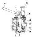
支持部6の内部構造を図2〜5に示す。図2は支持部における水平部8の内部機構を示す斜視図、図3は同正面図、図4は同底面図、図5は図3のA-A断面図である。図2に示すように、支持部6にはC型アーム5の旋回機構と、旋回用モータ20と、切り替え機構が含まれる。モータ20の駆動力は切り替え機構のクラッチ60で駆動ギア70に伝達・解除でき、伝達時は駆動ギア70に噛合する従動ギア10を電動回転させる。
【0022】
<旋回機構>
旋回機構は従動ギア10と、このギアと同軸の旋回軸と、旋回軸の軸受けとを具えている。図2では、旋回軸と軸受けは内ケース11内に収納されているため図示しておらず、内ケース11の端部に露出する従動ギア10のみを示している。これら従動ギア10と内ケース11は図1に示す外ケース13内に収納されている。
【0023】
<旋回用モータ>
旋回用モータ20は、内ケース側方に装着されて、電動旋回時、旋回機構を駆動してC型アーム5を旋回させるための駆動源である。このモータ20には電磁ブレーキが具えられ、手動旋回時、C型アーム5の旋回位置の固定に利用される。
【0024】
<切り替え機構>
切り替え機構は、レバー操作によりモータ自体を水平部8の軸方向に前進後退するスライド機構と、この進退動作によりモータ20の駆動力を従動ギア10に断続するクラッチ60とを有する。
【0025】
スライド機構の詳細を図2〜6に基づいて説明する。図6は図3におけるB-B断面図である。モータ20のスライドは図2〜4に示すレバー30の操作により、図5に示すカム31を回転させ、カム31の偏心量を利用してモータ20を押圧することで行う。モータ20はガイド32を介してスライド自在に保持され、カム31の押圧によりクラッチ60の断続を行う。
【0026】
図6に示すように、レバー30は円筒状のブロック33に固定され、このブロック33の下方に操作軸34が伸延されている。カム31は操作軸34の一部を切り欠いて構成される。カム31の断面は優弧31Aと直線31Bで囲まれる形状である(図5)。図5はカム31の直線31Bが後述する軸ガイド51に当接しており、モータ20は前進してクラッチ60が接続された状態を示している。さらに、カム31の優弧31Aには突起部35が形成されている。この突起部35は後述する安全棒80を動作させるためのものである。
【0027】
上記ブロック33の上部にはブロック33を貫通するプランジャ40が設けられ、下部には位置決め板41が設けられている(図6)。このプランジャ40と位置決め板41は手動旋回と電動旋回の選択に用いられ、電動旋回の場合はレバー30の回転位置を固定することに用いる。位置決め板41は、ほぼ90°の範囲に亘って設けられた円弧状の長孔と、この長孔の端部からさらに約90°離れた位置に設けられた円孔を有する。長孔または円孔にはプランジャ40の端部が嵌合され、長孔に嵌合されているときは手動旋回が、円孔に嵌合されているときは電動旋回が選択される。従って、プランジャ40を一旦引き上げて長孔との嵌合または円孔との嵌合を切り替えない限り、手動旋回と電動旋回とを切り替えることはできず、誤った旋回方式の選択を防止できる。
【0028】
モータ20は内ケース側に固定した一対のガイド32を介してハウジング36に装着されている(図3〜図4)。このハウジング内にモータ20とギアヘッド21が装着される。ハウジング36の内面とガイド32との間には圧縮バネ37が介在され、常時ハウジング36がカム側に押圧する状態に保持している。図3〜4にはガイド32の他、ハウジング両側を接続する補強板38が記載されているが、図2では、ガイド32および補強板38は省略している。
【0029】
クラッチ60が衝撃的に接続されないように緩衝機構を設けた。緩衝機構は、図5に示すように、ハウジング36に固定された筒ガイド50の内部に軸ガイド51をスライド自在にはめ込み、筒ガイド50の内側端面と軸ガイド端面との間に圧縮バネ53を介在させる。軸ガイド51の端面がカム31に押圧されると、圧縮バネ53を介してモータ20(ハウジング36)のスライドが行われるため、クラッチ60を衝撃的に連結することを抑制できる。
【0030】
クラッチ60は、駆動側摩擦板61と従動側摩擦板62とを有し、前者はギアヘッド21から伸延する駆動軸22に一体化されて、後者は駆動ギア70のギア軸71と一体化されている。駆動軸22はベアリング23(図5)を介してハウジング36に対して回転自在に保持され、ギア軸71はベアリング72を介してギア支持片73に対して回転自在に保持されている。ギア支持片73はベース74を介して内ケース11に固定される(図3)。
【0031】
(旋回角制限機構)
結石破砕用途に用いる場合、C型アーム5の旋回角は±30°程度で十分なため、電動旋回時にはC型アームの旋回角を制限する旋回角制限機構を設けた。この制限機構には、機械的機構と電気的機構の双方がある。
【0032】
<機械的旋回角制限機構>
機械的機構として、従動ギア10(回転体)の側面に円弧孔14を形成し、この円弧孔14に嵌脱する安全棒80を用いた(図2)。安全棒80は、図4に示すように、支持筒81を介してベース74にスライド自在に装着されており、一端にカム31の突起部35に押圧される接触片82(図5、図6、図8)が固定されている。支持筒81と接触片82との間には圧縮バネ83が介在され、常時安全棒80を従動ギア10から離れる方向に押圧している。レバー操作によりカムの優弧31Aが軸ガイド51に接触する状態としてさらにカム31を回転させると、突起部35が接触片82を押圧し、安全棒80を従動ギア側にスライドさせる(図5)。そして、安全棒80の他端が従動ギアの円弧孔14に嵌合すると、従動ギア10は円弧孔14の範囲でしか回転できないため、C型アーム5の旋回角が制限されることになる。図7に従動ギアの平面図を示す。本例では、円弧孔14はほぼ60°の範囲に形成している。
【0033】
<電気的旋回角制限機構>
電気的機構として、従動ギア10(回転体)に固定された旋回角規定部15と、この規定部15に接触するマイクロスイッチ90A〜90F(第一スイッチ手段)とを用いた。図2に示すようにマイクロスイッチ90A〜90F は内ケース11に固定されている。一方、旋回角規定部15は、図7に示すように、従動ギア10に固定された一対の円弧状の凸部である。この凸部の一端側は段階状の接触端15A〜15Dを有している。各々突出した接触端15B、15Cが30°、後退した接触端15A、15Dが20°の旋回角に対応している。マイクロスイッチ90A〜90Dが接触端15A〜15Dに当接したときにC型アーム5が規定の旋回角になっており、停止信号を出力してC型アーム5の旋回を停止させる。本例で、20°の場合にも旋回角の制限機構を設けたのは、より小さい旋回角で結石への位置調整を行うためである。旋回角を20°程度としただけでも結石破砕装置の衝撃波の焦点を結石に位置合わせできる場合があり、その場合は30°まで旋回することなく、より迅速な調整が可能となる。
【0034】
2つある旋回角規定部のうち、一方の旋回角規定部には中間部に一対の接触端15E、15Fを形成している。この接触端15E、15Fは互いに逆向きに構成されて、一対のマイクロスイッチ90E、90Fとの接触に対応しており、C型アーム5の旋回角が0°の際の従動ギア10の回転位置を検出する。一対のマイクロスイッチ90E、90Fが共にオン(オフ)になった場合にC型アーム5の旋回角が0°と判断する。一対のマイクロスイッチ90E、90Fを用いているのは、ある旋回角から0°の状態に復帰する場合、左右のどちらに従動ギア10を回転させれば良いかを判断するためである。例えば、図7の左側のマイクロスイッチ90Eがオンで、右側のマイクロスイッチ90Fがオフであった場合、従動ギア10は0°の位置より左回りに回転した位置にあるとする。0°への復帰が指令されれば、両スイッチ90E、90Fがオンになるまで右回りに回転させれば良い。逆に、左側のマイクロスイッチ90Eがオフで、右側のマイクロスイッチ90Fがオンであった場合、従動ギア10は0°の位置より右回りに回転した位置にあることになる。そのため、0°への復帰が指令されれば、両スイッチ90E、90Fがオンになるまで左回りに回転させれば良い。
【0035】
上記の接触端15A〜15Fはいずれもテーパー状に形成されて、マイクロスイッチ90A〜90Fの当接の衝撃を緩衝するように構成されている。
【0036】
なお、図7はC型アーム5の旋回角が0°の場合における従動ギア10の向きを示しており、各マイクロスイッチ90A〜90Fは、どの接触端15A〜15Fに対応しているかを模式的に示しているに過ぎない。従って、図7は従動ギア10に対する実際のマイクロスイッチ90A〜90Fの配置個所や向きを示したものではない。
【0037】
(安全棒の従動ギアへの嵌合確認機構)
安全棒80が従動ギアの円弧孔14に嵌合することで、旋回角が制限されることは前述の通りである。さらに、本例では、この嵌合が確実に行われたかどうかを電気的に検出する確認機構を設けた。この確認機構は安全棒80のスライドをマイクロスイッチ84(第二スイッチ手段)で検出する。図8は図3における一点鎖線の円内の詳細図である。図8に示すように、安全棒80と一体の接触片82がガイド85に沿ってスライドする。ここで、接触片82にテーパー部を形成し、安全棒80が円弧孔14に嵌合したとき、テーパー部に接触するようにマイクロスイッチ84を配置する。このマイクロスイッチ84からの信号により、C型アーム5の電動旋回の可否を判断する。
【0038】
(制御機構)
上記構成のC型アーム支持部6は、フットスイッチ7の操作により制御される。その制御機構のブロック図を図9に示す。フットスイッチ7は、3つのペダルを具え、それぞれ「左回転」、「右回転」、「0°」に対応している。「0°」はC型アームの旋回角に関らず、0°の状態に復帰させる。
【0039】
各マイクロスイッチ90A〜90Fの信号とフットスイッチ7からの制御信号は旋回動制御回路100に出力され、さらにモータ駆動回路101を介してモータ20の回転・停止と回転方向とを制御する。
【0040】
マイクロスイッチ90A〜90Dまでは、いずれもオン(またはオフ)になることで旋回停止信号を出力する。例えば、「左回転」のペダルを踏むとC型アーム5は左旋回を開始し、左に20°旋回した所で接触端15Aがマイクロスイッチ90Aに当接してより停止信号が出力されてC型アーム5の旋回は止められる(図7)。さらに30°までC型アーム5を旋回させるには、一旦「左回転」のペダルを放して再度踏みなおす。そして、左に30°旋回した所で接触端15Bがマイクロスイッチ90Bに当接して停止信号が出力されてC型アーム5の旋回は止められる。
【0041】
一対のマイクロスイッチ90E、90Fは双方がオン(またはオフ)になった場合のみ旋回停止信号を出力する。「0°」のペダルを踏むと、一対のマイクロスイッチのうちいずれがオン(オフ)になっているかと言うことから0°に復帰するための旋回方向を検出し、双方がオンになるまで検出方向にC型アーム5を旋回させる。
【0042】
マイクロスイッチ84は、オン(またはオフ)になることで安全棒80が従動ギア10に嵌合したと判断して電動旋回を許容し、オフであれば安全棒80が従動ギア10に嵌合していないと判断して電動旋回を不能にする。従って、電動旋回可能な場合は、上記フットスイッチ7とマイクロスイッチ90A〜90Fまでの信号によりC型アーム5の旋回を制御可能であるが、電動旋回不能であれば、フットスイッチ7のいずれのペダルを操作してもモータ20は駆動されない。
【0043】
(旋回手順と動作)
<手動旋回>
手動旋回する場合、プランジャ40の先端を位置決め板の長孔にはめ込み、レバー30は図2のA位置からB位置の間で操作可能な状態とする。A位置で手動旋回可能となり、B位置で旋回位置固定となる。
【0044】
通常、レバー30はB位置に保持されてC型アーム5の旋回はできない。このとき、カム31の優弧31Aが軸ガイド51に当接し、モータ20は前進してクラッチ60が接続された状態となる。しかし、安全棒80は従動ギアの円弧孔14に嵌合しておらず、かつマイクロスイッチ84がオフとなっており電動旋回はできない。そして、モータ20は電磁ブレーキが作動して回転せず、モータ20に接続される駆動ギア70および従動ギア10も回転させることができない。そのため、C型アーム5の旋回位置が保持される。
【0045】
手動旋回する場合、レバー30をA位置に移動する。このとき、プランジャ40の先端は位置決め板の長孔内で一端から他端に移動する。また、カム31の直線31Bが軸ガイド51に当接し、モータ20は後退してクラッチ60が離れた状態となり、駆動力を従動ギア10に伝達できない。さらに、安全棒80も従動ギアの円弧孔14に嵌合していない。そのため、従動ギア10はフリーの状態となり、C型アーム5を手動で旋回することができる。本発明装置では、±210°の旋回ができるように構成した。所定の角度まで旋回できれば、再度レバー30をB位置に戻してC型アーム5の位置を固定すれば良い。
【0046】
<電動旋回>
電動旋回する場合、レバー30をB位置からC位置に移動する。この移動を行うには、プランジャ40を一旦引き上げた後、その先端を長孔から円孔へとはめ直す必要がある。
【0047】
このレバー操作に伴ってB位置と同じくカム31が回転され、優弧31Aが軸ガイド51に当接し、モータ20は前進してクラッチ60が接続された状態となる。同時にカム31の突起部35が安全棒80をスライドさせ、従動ギアの円弧孔14に嵌合させる。そして、マイクロスイッチ84がオンになり、電動旋回可能な状態になる。この後はフットスイッチ7を操作して、所定の角度にC型アーム5を旋回させれば良い。
【0048】
【発明の効果】
以上説明したように、本発明装置によれば、C型アームを手動による旋回と電動による旋回に切り替えて動作することができる。そのため、外科整形に用いる場合は手動にて広範囲に素早く旋回を行うことができる。一方、結石破砕装置と組み合わせて用いる場合は、遠隔操作で電動によるC型アームの旋回が行え、旋回と同時に患者の乗ったテーブルの位置設定が容易にできるため、衝撃波の焦点を迅速に結石へ位置調整することができる。
【図面の簡単な説明】
【図1】本発明移動形X線装置の外観図である。
【図2】図1の装置における支持部の内部機構を示す斜視図である。
【図3】図1の装置における支持部の内部機構を示す正面図である。
【図4】図1の装置における支持部の内部機構を示す底面図である。
【図5】図3のA-A断面図である。
【図6】図3のB-B断面図である。
【図7】従動ギアの平面図である。
【図8】図3における一点鎖線の円内の詳細図である。
【図9】本発明装置におけるC型アームの旋回制御機構のブロック図である。
【符号の説明】
1 移動台車
2 X線制御部
3 X線発生部
4 X線受像部
5 C型アーム
6 支持部
7 フットスイッチ
8 水平部
9 傾斜部
10 従動ギア
11 内ケース
13 外ケース
14 円弧孔
15 旋回角規定部
15A〜15F 接触端
20 旋回用モータ
21 ギアヘッド
22 駆動軸
23 ベアリング
30 レバー
31 カム
31A 優弧
31B 第一直線
31C 第二直線
32 ガイド
33 ブロック
34 操作軸
35 突起部
36 ハウジング
37 圧縮バネ
38 補強板
40 プランジャ
41 位置決め板
50 筒ガイド
51 軸ガイド
53 圧縮バネ
60 クラッチ
61 駆動側摩擦板
62 従動側摩擦板
70 駆動ギア
71 ギア軸
72 ベアリング
73 ギア支持片
74 ベース
80 安全棒
81 支持筒
82 接触片
83 圧縮バネ
84 マイクロスイッチ
85 ガイド
90A〜90F マイクロスイッチ
100 旋回動制御回路
101 モータ駆動回路[0001]
BACKGROUND OF THE INVENTION
The present invention relates to a mobile X-ray apparatus. In particular, the present invention relates to a mobile X-ray apparatus that can switch the rotation of a C-arm between manual and electric depending on the use of X-ray image capturing.
[0002]
[Prior art]
A mobile X-ray apparatus, which is mainly used for X-ray imaging in orthopedics, has a C-arm with an X-ray generator at one end and an X-ray receiver at the other end, and is mounted on a mobile carriage. Yes. Since such an X-ray apparatus is used in a relatively small operating room, hospital room or the like, a small, light and compact apparatus is desired. For this reason, the C-arm is pivoted manually, lightly and quickly.
[0003]
In recent years, a method has been used in which this mobile X-ray apparatus is combined with a calculus crushing device and treated with the crushing device while checking the position of the calculus. In this method, it is necessary to perform an X-ray fluoroscopic imaging by turning the C-arm about 30 ° left and right and adjusting the shock wave focus of the calculus breaking device to match the calculus in the body. For example, if you can see a calculus in the center of the screen when the turning angle is 30 ° to the left, but there is no calculus in the center of the image when you turn to the right 30 °, it will be in the center of the X-ray generator and X-ray receiver The stone is not located. In that case, the X-ray fluoroscopic imaging with different turning angles and the movement of the table on which the patient is placed are repeated so that the stone is positioned at the center of the image at any turning angle.
[0004]
In order to perform such adjustment quickly, it may be considered that the C-arm is turned electrically. If this turning is motorized, the table on which the patient is placed can be moved while turning the C-arm, and the positioning operation can be easily performed.
[0005]
[Problems to be solved by the invention]
However, if the C-arm is swung manually or only by electric power, there is a problem that it is not possible to realize a swivel operation that is optimal for both orthopedic surgery and stone crushing.
[0006]
When the C-arm is swung manually only, it is preferable for orthopedic use because it is light and can be moved quickly. However, for stone crushing, it is necessary to repeat the operation of manually turning the C-arm to perform X-ray fluoroscopy and moving the table on which the patient is placed. For this reason, there is a problem that it takes time to set and position the C-arm.
[0007]
On the other hand, when the C-arm is turned only by electric power, the positioning operation is simplified because the table can be moved while checking the calculus position for calculus crushing. However, when used in a limited space such as an operating field for orthopedic surgery with a high degree of urgency, there is a drawback that it is difficult to perform delicate positioning by electric turning, and quick positioning cannot be performed. In addition, in the unlikely event that the C-type arm malfunctions, a malfunction prevention mechanism is necessary to prevent the arm from hitting the patient directly, and the complexity of the apparatus is inevitable.
[0008]
Accordingly, an object of the present invention is to provide a mobile X-ray apparatus capable of a pivoting motion that is optimal for both orthopedic and lithotripsy applications.
[0009]
[Means for Solving the Problems]
The present invention achieves the above object by making it possible to switch the turning of the C-arm between manual and electric.
[0010]
That is, the mobile X-ray apparatus of the present invention is configured so that the C-type arm can turn about the X-ray generating unit at one end and the C-type arm that supports the X-ray image receiving unit at the other end and the horizontal axis as the turning center axis. In a mobile X-ray apparatus having a turning mechanism for holding, a motor for applying rotational power to the turning mechanism for electrically turning the C-arm to the turning mechanism, and a driving force of the motor transmitted to the turning mechanism. A switching mechanism that intermittently switches between manual turning and electric turning of the C-arm is provided.
[0011]
By switching the C-arm to electric and manual switching, when using it in combination with a calculus crusher, the electric rotation can save time and effort for positioning. When used for orthopedic surgery, it is possible to switch to manual pivoting for quick positioning. The electric turning operation is preferably performed by remote operation means such as a foot switch. Accordingly, the table on which the patient is placed can be easily moved simultaneously with the turning of the C-arm, and the positioning operation to the calculus position is simplified.
[0012]
A specific example of the switching mechanism is preferably provided with a slide mechanism for moving the manual motor forward and backward, and a clutch for intermittently connecting the driving force of the motor to the turning mechanism in accordance with the forward and backward movement. The slide mechanism preferably includes a guide that holds the motor slidably and a cam that is rotated and pressed by lever operation. As the clutch, an engagement clutch, a friction clutch, an electromagnetic clutch, or the like can be used.
[0013]
When the device of the present invention is used in combination with a calculus breaking device, the C-type arm is electrically swiveled, that is, the driving force of the motor is transmitted to the turning mechanism. In stone crushing applications, a turning angle of about ± 30 ° is sufficient, and therefore it is preferable to provide a turning angle limiting mechanism. Examples of the turning angle limiting mechanism include an electrical limiting mechanism using a switch and a mechanical limiting mechanism using fitting of members. Only one of the electrical and mechanical limiting mechanisms may be provided, but it is more desirable to provide both.
[0014]
(1) Electrical restriction mechanism: a rotating body that transmits the driving force of the turning motor to the turning of the C-arm, a turning angle defining portion provided on the rotating body, and the turning angle as the rotating body rotates. First switch means for contacting the defining portion and outputting a turning stop signal. The rotating body may be either a gear or a shaft constituting a driving force transmission mechanism interposed between the motor and the C-arm. Usually, it is preferable to use a gear coaxial with the swivel axis of the C-arm as a rotating body. A micro switch or the like can be used as the first switch means. The turning angle defining portion is preferably a convex portion or a concave portion that can be contacted by the first switch means.
[0015]
(2) X mechanical limiting mechanism: a rotating body that transmits the driving force of the turning motor to the turning of the C-arm, an arc hole provided in the rotating body, and an operation for intermittently driving the driving force of the motor to the turning mechanism And a safety rod that fits into and out of the arc hole. By specifying the range of the arc hole, the turning angle of the C-arm is mechanically limited. As the rotating body in this mechanical limiting mechanism, the same rotating body as in the electrical limiting mechanism can be used.
[0016]
On the other hand, when used for surgical shaping, the C-arm is manually turned, that is, the driving force of the motor is not transmitted to the turning mechanism. Since a wide swivel angle is required for surgical shaping applications, it is preferable that the swivel angle limiting mechanism is configured not to operate during manual swiveling. For example, there is provided second switch means for detecting the engagement / disengagement of the safety rod, the first switch means and the turning motor are activated only when they are fitted, and the first switch means and Control the turning motor not to operate. It is preferable to use a microswitch for the second switch means.
[0017]
Further, during manual turning, a mechanism for fixing the turning position of the C-arm is required. For this fixing, it is preferable to use an electromagnetic brake of a turning motor. For example, the connection relationship between the motor, the safety rod, and the turning mechanism is such that neither the motor nor the safety rod is connected to the turning mechanism, the motor is connected to the turning mechanism, but the safety rod is not connected to the turning mechanism, There are three ways in which both are connected to the turning mechanism. Manual turning is possible when neither the motor nor the safety rod is connected to the turning mechanism, and electric turning is possible when both the motor and the safety rod are connected to the turning mechanism. When the motor is connected to the turning mechanism but the safety rod is not connected to the turning mechanism, the C-arm is prevented from turning by the electromagnetic brake of the motor and the turning position is fixed. At that time, control is performed so that electric turning is not possible by a signal from the second switch means.
[0018]
Although the device of the present invention basically uses manual turning for surgical operation and electric turning for stone crushing, the use of the device of the present invention is not limited to these.
[0019]
DETAILED DESCRIPTION OF THE INVENTION
Embodiments of the present invention will be described below.
(Outline of X-ray device)
FIG. 1 is an external perspective view of the device of the present invention. The apparatus of the present invention is a C-arm having a moving carriage 1 that is driven by a running motor, an
[0020]
(Appearance of support part)
The support portion 6 is bent into a shallow V shape, and includes a box-shaped
[0021]
(Internal structure of support part)
The internal structure of the support part 6 is shown in FIGS. 2 is a perspective view showing an internal mechanism of the
[0022]
<Swivel mechanism>
The turning mechanism includes a driven
[0023]
<Rotating motor>
The turning
[0024]
<Switching mechanism>
The switching mechanism includes a slide mechanism for moving the motor itself forward and backward in the axial direction of the
[0025]
Details of the sliding mechanism will be described with reference to FIGS. 6 is a cross-sectional view taken along the line BB in FIG. The sliding of the
[0026]
As shown in FIG. 6, the
[0027]
A
[0028]
The
[0029]
A buffer mechanism is provided so that the clutch 60 is not shockedly connected. As shown in FIG. 5, the buffer mechanism is configured such that the
[0030]
The clutch 60 has a drive
[0031]
(Turning angle limiting mechanism)
When used for calculus crushing, a turning angle of the C-
[0032]
<Mechanical turning angle limiting mechanism>
As a mechanical mechanism, an
[0033]
<Electric turning angle limiting mechanism>
As an electrical mechanism, a turning
[0034]
Of the two turning angle defining portions, one turning angle defining portion has a pair of contact ends 15E and 15F formed in the intermediate portion. The contact ends 15E and 15F are configured in opposite directions to correspond to contact with the pair of
[0035]
Each of the contact ends 15A to 15F is formed in a taper shape so as to buffer the impact of the contact of the
[0036]
FIG. 7 shows the direction of the driven
[0037]
(Mechanism for checking the fitting of the safety rod to the driven gear)
As described above, the turning angle is limited by fitting the
[0038]
(Control mechanism)
The C-arm support portion 6 configured as described above is controlled by operating the foot switch 7. A block diagram of the control mechanism is shown in FIG. The foot switch 7 has three pedals and corresponds to “left rotation”, “right rotation”, and “0 °”, respectively. “0 °” returns to 0 ° regardless of the turning angle of the C-arm.
[0039]
The signals of the
[0040]
The
[0041]
The pair of
[0042]
When the
[0043]
(Turning procedure and operation)
<Manual turning>
When manually turning, the tip of the
[0044]
Normally, the
[0045]
When manually turning, the
[0046]
<Electric turning>
In the case of electric turning, the
[0047]
With this lever operation, the
[0048]
【The invention's effect】
As described above, according to the device of the present invention, the C-arm can be operated by switching between manual turning and electric turning. Therefore, when using it for surgical shaping, it can be swung quickly in a wide range manually. On the other hand, when used in combination with a lithotripter, the C-arm can be turned by remote control and the position of the table on which the patient is placed can be easily set at the same time as turning. The position can be adjusted.
[Brief description of the drawings]
FIG. 1 is an external view of a mobile X-ray apparatus according to the present invention.
2 is a perspective view showing an internal mechanism of a support portion in the apparatus of FIG. 1. FIG.
3 is a front view showing an internal mechanism of a support portion in the apparatus of FIG. 1. FIG.
4 is a bottom view showing an internal mechanism of a support portion in the apparatus of FIG. 1. FIG.
5 is a cross-sectional view taken along the line AA in FIG.
6 is a cross-sectional view taken along the line BB in FIG. 3;
FIG. 7 is a plan view of a driven gear.
FIG. 8 is a detailed view in a circle of an alternate long and short dash line in FIG. 3;
FIG. 9 is a block diagram of a turning control mechanism for a C-arm in the device of the present invention.
[Explanation of symbols]
1 Moving cart
2 X-ray controller
3 X-ray generator
4 X-ray receiver
5 C-type arm
6 Support section
7 Foot switch
8 Horizontal part
9 Inclined part
10 Driven gear
11 Inner case
13 Outer case
14 Arc hole
15 Turning angle setting part
15A-15F Contact end
20 Rotating motor
21 Gear head
22 Drive shaft
23 Bearing
30 lever
31 cams
31A dominant arc
31B first straight line
31C second straight line
32 Guide
33 blocks
34 Operation axis
35 Protrusion
36 Housing
37 Compression spring
38 Reinforcing plate
40 Plunger
41 Positioning plate
50 Tube guide
51 axis guide
53 Compression spring
60 clutch
61 Drive friction plate
62 Driven friction plate
70 Drive gear
71 Gear shaft
72 Bearing
73 Gear support piece
74 base
80 safety rod
81 Support tube
82 Contact piece
83 Compression spring
84 Micro switch
85 Guide
90A ~ 90F micro switch
100 Swing motion control circuit
101 Motor drive circuit
Claims (3)
前記C型アームを電動によって旋回させるための回転動力を前記旋回機構に与えるモータと、前記旋回機構へ伝達される前記モータの駆動力を断続して前記C型アームの手動旋回と電動旋回を切り替える切り替え機構と、を備え、前記電動旋回を行う際は、前記C型アームの旋回角度を制限する電気的制限機構、もしくは機械的制限機構の少なくてもいずれか一方の制限機構を有し、前記切り替え機構は、レバー操作により、前記モータの位置を、スライド機構を用いて前進後退させ、前記前進後退動作により、前記モータの回転動力をクラッチと駆動ギアを用いて、前記旋回機構の従動ギアに伝達及び非伝達すると共に、前記レバー操作は、前記モータの回転とブレーキとを合わせて制御することで、前記C型アームの手動旋回、電動旋回、及びブレーキ、の3つの状態を制御する機構を備えることを特徴とする移動型X線装置。A movable X having a C-type arm that supports an X-ray generation unit at one end and an X-ray image receiving unit at the other end, and a turning mechanism that holds the C-type arm so that the C-type arm can turn about a horizontal axis. In the wire device,
A motor for turning the C-arm by electric power to the turning mechanism and a driving force of the motor transmitted to the turning mechanism are intermittently switched between manual turning and electric turning of the C-arm. A switching mechanism, and when performing the electric turning, at least one of the electric restriction mechanism and the mechanical restriction mechanism for restricting the turning angle of the C-arm, The switching mechanism moves the position of the motor forward and backward using a slide mechanism by lever operation, and uses the clutch and drive gear to drive the rotational power of the motor to the driven gear of the turning mechanism using the forward and backward operation. Transmission and non-transmission, and the lever operation is controlled by combining the rotation of the motor and the brake, so that the C-arm is manually turned and electrically turned. And mobile X-ray apparatus, characterized in that it comprises a mechanism for controlling the three states of the brake.
前記C型アームを電動によって旋回させるための回転動力を前記旋回機構に与えるモータと、前記旋回機構へ伝達される前記モータの駆動力を断続して前記C型アームの手動旋回と電動旋回を切り替える切り替え機構と、を備え、前記電動旋回を行う際は、A motor for turning the C-arm by electric power to the turning mechanism and a driving force of the motor transmitted to the turning mechanism are intermittently switched between manual turning and electric turning of the C-arm. A switching mechanism, and when performing the electric turning,
前記C型アームの旋回角度を制限する機械的制限機構を有し、前記機械的制限機構は、前記C型アームの旋回に伝動する回転体と、前記回転体に設けられた円弧孔と、前記円弧孔と、前記モータの回転動力を前記旋回機構に断続する動作に連動して前記円弧孔に嵌脱する安全棒を備え、前記円弧孔の範囲において機械的に前記C型アームの旋回角度を制限することを特徴とする移動型X線装置。A mechanical restriction mechanism for restricting a turning angle of the C-arm, and the mechanical restriction mechanism includes a rotating body that transmits the turning of the C-type arm, an arc hole provided in the rotating body, An arc hole and a safety rod that fits in and out of the arc hole in conjunction with an operation of intermittently rotating the rotational power of the motor to the turning mechanism, and mechanically adjusts the swivel angle of the C-arm in the range of the arc hole. A mobile X-ray apparatus characterized by limiting.
Priority Applications (1)
| Application Number | Priority Date | Filing Date | Title |
|---|---|---|---|
| JP2000298196A JP4731666B2 (en) | 2000-09-29 | 2000-09-29 | Mobile X-ray device |
Applications Claiming Priority (1)
| Application Number | Priority Date | Filing Date | Title |
|---|---|---|---|
| JP2000298196A JP4731666B2 (en) | 2000-09-29 | 2000-09-29 | Mobile X-ray device |
Publications (3)
| Publication Number | Publication Date |
|---|---|
| JP2002102214A JP2002102214A (en) | 2002-04-09 |
| JP2002102214A5 JP2002102214A5 (en) | 2007-11-01 |
| JP4731666B2 true JP4731666B2 (en) | 2011-07-27 |
Family
ID=18780185
Family Applications (1)
| Application Number | Title | Priority Date | Filing Date |
|---|---|---|---|
| JP2000298196A Expired - Fee Related JP4731666B2 (en) | 2000-09-29 | 2000-09-29 | Mobile X-ray device |
Country Status (1)
| Country | Link |
|---|---|
| JP (1) | JP4731666B2 (en) |
Families Citing this family (7)
| Publication number | Priority date | Publication date | Assignee | Title |
|---|---|---|---|---|
| EP1910907A2 (en) * | 2005-07-25 | 2008-04-16 | Koninklijke Philips Electronics N.V. | System and method for providing lateral and frontal x-ray images of a patient |
| US7954996B2 (en) * | 2008-07-08 | 2011-06-07 | General Electric Company | Positioning system with tilting arm support for imaging devices |
| JP6362852B2 (en) * | 2013-11-20 | 2018-07-25 | キヤノンメディカルシステムズ株式会社 | Mobile X-ray diagnostic device |
| CN109363694A (en) * | 2018-09-18 | 2019-02-22 | 深圳圣诺医疗设备股份有限公司 | The rotating device and breast X-ray imaging system of breast X-ray imaging system |
| CN114401672A (en) * | 2019-09-30 | 2022-04-26 | 富士胶片株式会社 | Radiation imaging apparatus and control method for radiation imaging apparatus |
| JP7129963B2 (en) * | 2019-09-30 | 2022-09-02 | 富士フイルム株式会社 | radiography equipment |
| JP7301704B2 (en) * | 2019-09-30 | 2023-07-03 | 富士フイルム株式会社 | radiography equipment |
Citations (7)
| Publication number | Priority date | Publication date | Assignee | Title |
|---|---|---|---|---|
| GB1175032A (en) * | 1967-03-30 | 1969-12-23 | Man Ets De | Systems for driving and guiding electric supply cables |
| JPS56124408U (en) * | 1980-02-19 | 1981-09-22 | ||
| JPS63158312U (en) * | 1987-04-06 | 1988-10-17 | ||
| JPH03173537A (en) * | 1989-11-22 | 1991-07-26 | Philips Gloeilampenfab:Nv | X-ray inspection device |
| JPH0788107A (en) * | 1993-09-27 | 1995-04-04 | Toshiba Medical Eng Co Ltd | Support rotary mechanism of ceiling hanging x-ray diagnostic device |
| JPH11188024A (en) * | 1997-12-26 | 1999-07-13 | Shimadzu Corp | X ray diagnostic device |
| JP2000070248A (en) * | 1998-08-31 | 2000-03-07 | Siemens Ag | Medial x-ray device, especially vessel photographing device |
Family Cites Families (3)
| Publication number | Priority date | Publication date | Assignee | Title |
|---|---|---|---|---|
| JPS56124408A (en) * | 1980-03-06 | 1981-09-30 | Shigeru Kobayashi | Removing device for sand contained in miscellaneous waste water |
| JPH0643846B2 (en) * | 1986-08-18 | 1994-06-08 | 三菱電機株式会社 | Hiding plate for fixing screws |
| DE19746079C2 (en) * | 1997-10-17 | 1999-10-28 | Siemens Ag | Medical facility with a carrying device for at least one component |
-
2000
- 2000-09-29 JP JP2000298196A patent/JP4731666B2/en not_active Expired - Fee Related
Patent Citations (7)
| Publication number | Priority date | Publication date | Assignee | Title |
|---|---|---|---|---|
| GB1175032A (en) * | 1967-03-30 | 1969-12-23 | Man Ets De | Systems for driving and guiding electric supply cables |
| JPS56124408U (en) * | 1980-02-19 | 1981-09-22 | ||
| JPS63158312U (en) * | 1987-04-06 | 1988-10-17 | ||
| JPH03173537A (en) * | 1989-11-22 | 1991-07-26 | Philips Gloeilampenfab:Nv | X-ray inspection device |
| JPH0788107A (en) * | 1993-09-27 | 1995-04-04 | Toshiba Medical Eng Co Ltd | Support rotary mechanism of ceiling hanging x-ray diagnostic device |
| JPH11188024A (en) * | 1997-12-26 | 1999-07-13 | Shimadzu Corp | X ray diagnostic device |
| JP2000070248A (en) * | 1998-08-31 | 2000-03-07 | Siemens Ag | Medial x-ray device, especially vessel photographing device |
Also Published As
| Publication number | Publication date |
|---|---|
| JP2002102214A (en) | 2002-04-09 |
Similar Documents
| Publication | Publication Date | Title |
|---|---|---|
| US7084364B2 (en) | Dual control footswitch assembly | |
| US9025730B2 (en) | Electrically controlled brakes for arm joints on a mini C-arm mobile X-ray system | |
| EP2347693B1 (en) | Endoscope apparatus | |
| JP6082553B2 (en) | Brake release mechanism and medical manipulator having the same | |
| JP4731666B2 (en) | Mobile X-ray device | |
| JP6042678B2 (en) | Brake mechanism and medical manipulator having the same | |
| JP2009106689A (en) | X-ray imaging apparatus | |
| JP4996237B2 (en) | Ophthalmic laser treatment device | |
| JP4349652B2 (en) | X-ray equipment | |
| JP4484423B2 (en) | X-ray equipment | |
| EP3801272A1 (en) | Compression arm devices and methods | |
| JP3977017B2 (en) | Laser therapy device | |
| JPH11285491A (en) | Photofluoroscope | |
| JP2003175030A (en) | X-ray imaging apparatus | |
| CN111658021A (en) | Universal prostate puncture device | |
| JP4354043B2 (en) | Endoscope holder | |
| JP4094429B2 (en) | Enable switch | |
| JPH10225450A (en) | X-ray diagnostic device | |
| JP4311165B2 (en) | C-arm X-ray device | |
| JP4176255B2 (en) | Laser therapy device | |
| JP3647726B2 (en) | Ophthalmic operating table | |
| JP4137437B2 (en) | Medical X-ray device | |
| JP3628153B2 (en) | Panoramic X-ray equipment | |
| JP2011161139A (en) | Diagnostic x-ray equipment | |
| JPH0127795Y2 (en) |
Legal Events
| Date | Code | Title | Description |
|---|---|---|---|
| A521 | Request for written amendment filed |
Free format text: JAPANESE INTERMEDIATE CODE: A523 Effective date: 20070914 |
|
| A621 | Written request for application examination |
Free format text: JAPANESE INTERMEDIATE CODE: A621 Effective date: 20070914 |
|
| A131 | Notification of reasons for refusal |
Free format text: JAPANESE INTERMEDIATE CODE: A131 Effective date: 20100413 |
|
| A521 | Request for written amendment filed |
Free format text: JAPANESE INTERMEDIATE CODE: A523 Effective date: 20100526 |
|
| A131 | Notification of reasons for refusal |
Free format text: JAPANESE INTERMEDIATE CODE: A131 Effective date: 20101129 |
|
| A521 | Request for written amendment filed |
Free format text: JAPANESE INTERMEDIATE CODE: A523 Effective date: 20110113 |
|
| A131 | Notification of reasons for refusal |
Free format text: JAPANESE INTERMEDIATE CODE: A131 Effective date: 20110131 |
|
| A521 | Request for written amendment filed |
Free format text: JAPANESE INTERMEDIATE CODE: A523 Effective date: 20110329 |
|
| TRDD | Decision of grant or rejection written | ||
| A01 | Written decision to grant a patent or to grant a registration (utility model) |
Free format text: JAPANESE INTERMEDIATE CODE: A01 Effective date: 20110418 |
|
| A01 | Written decision to grant a patent or to grant a registration (utility model) |
Free format text: JAPANESE INTERMEDIATE CODE: A01 |
|
| A61 | First payment of annual fees (during grant procedure) |
Free format text: JAPANESE INTERMEDIATE CODE: A61 Effective date: 20110420 |
|
| FPAY | Renewal fee payment (event date is renewal date of database) |
Free format text: PAYMENT UNTIL: 20140428 Year of fee payment: 3 |
|
| R150 | Certificate of patent or registration of utility model |
Free format text: JAPANESE INTERMEDIATE CODE: R150 |
|
| LAPS | Cancellation because of no payment of annual fees |