JP4730510B2 - Image forming apparatus - Google Patents
Image forming apparatus Download PDFInfo
- Publication number
- JP4730510B2 JP4730510B2 JP2004203758A JP2004203758A JP4730510B2 JP 4730510 B2 JP4730510 B2 JP 4730510B2 JP 2004203758 A JP2004203758 A JP 2004203758A JP 2004203758 A JP2004203758 A JP 2004203758A JP 4730510 B2 JP4730510 B2 JP 4730510B2
- Authority
- JP
- Japan
- Prior art keywords
- display
- image forming
- screen
- display screen
- forming apparatus
- Prior art date
- Legal status (The legal status is an assumption and is not a legal conclusion. Google has not performed a legal analysis and makes no representation as to the accuracy of the status listed.)
- Expired - Fee Related
Links
Images


Description
この発明は、原稿の読み取りなどによって得られる画像情報に基づいて画像形成を行う画像形成装置に関するものである。 The present invention relates to an image forming apparatus that forms an image based on image information obtained by reading a document.
複写機、プリンタ、ファクシミリ、複合機などの画像形成装置は、画像情報に基づいて画像を形成する画像形成手段を有しており、さらに複写機、ファクシミリ、複合機などでは原稿を読み取って画像情報を得る読み取り手段を備えている。画像情報は、メモリなどの画像記憶手段に記憶される。
上記画像形成装置では、原稿を読み取る際の読み取り条件や画像形成に際しての画像形成条件などの各種動作条件の設定が可能になっており、多くの装置では表示画面上でこれら設定の入力が可能になっている。また、多くの画像形成装置では、ジョブの予約設定が可能になっており、複数ジョブの管理も表示画面上で行うことができる。また表示画面は、装置の機械状態を表示する画面としても使用される。このように、表示画面は複数の状況に応じて内容を変えて表示するように構成されており、一つの画面を複数の役割で兼用しそれぞれの状況に応じた表示がなされるように画面の表示制御がなされている。
Image forming apparatuses such as copiers, printers, facsimiles, and multifunction machines have image forming means for forming images based on image information. Further, copiers, facsimiles, multifunction machines, and the like read image data by reading originals. Is provided. The image information is stored in image storage means such as a memory.
In the image forming apparatus, it is possible to set various operating conditions such as a reading condition when reading a document and an image forming condition when forming an image, and many apparatuses can input these settings on a display screen. It has become. In many image forming apparatuses, job reservation settings can be made, and a plurality of jobs can be managed on the display screen. The display screen is also used as a screen for displaying the machine state of the apparatus. In this way, the display screen is configured to display with different contents according to a plurality of situations, and the screen can be displayed according to each situation by using one screen for a plurality of roles. Display control is performed.
例えば、ジョブ毎に設定画面を持つ画面構成とし、異常が発生した際には、設定画面上に異常画面を貼り付け設定入力を受け付けないで異常発生状況の解消を促す画面表示とする画像形成装置が知られている。 For example, an image forming apparatus having a screen configuration with a setting screen for each job, and in the event of an abnormality, an abnormal screen is pasted on the setting screen and a screen display that prompts the user to eliminate the abnormality occurrence state without accepting setting input It has been known.
また、新たなジョブの設定操作中、動作している別のジョブに障害が発生した場合、一定時間だけ異常発生を表示して設定の継続を可能にし、設定完了後に再度異常発生を表示する画像形成装置が提案されている(特許文献1参照)。
しかし、前者の画像形成装置では、異常が発生した際に設定入力が受け付けられなくなるので、次ジョブの予約や異常発生箇所と関わりなく動作する機能の実行ができないなどの制約があり、操作者の事情に拘わらず作業を中断せざるを得ないという問題がある。
例えば、1つのジョブを大量に印刷し、かつ次ジョブの読取りを連続的に実施するプロダクション向け印刷装置において、紙づまり等の出力系の異常が発生した場合、関係のないジョブの操作(次ジヨブ設定や読取り指示)を中断しなければならなくなる。
また、後者の画像形成装置では、設定操作中に他のジョブで異常が発生しても設定操作を継続することができるという利点がある。しかし、装置によって予め定めた作業時間が許容されるだけであり、装置事情に制約を受けざるを得ないという問題がある。また、異常が発生した際に作業をしていた設定操作が完了した後は、異常発生表示状態になるため、新たな設定操作等が困難であるという問題がある。
However, since the former image forming apparatus cannot accept setting input when an abnormality occurs, there are restrictions such as the reservation of the next job and the execution of functions that are independent of the location of the abnormality, etc. There is a problem that work must be interrupted regardless of circumstances.
For example, in a production printing device that prints a large amount of one job and continuously reads the next job, if an output system abnormality such as a paper jam occurs, the operation of the unrelated job (next job) Setting and reading instructions) must be interrupted.
Further, the latter image forming apparatus has an advantage that the setting operation can be continued even if an abnormality occurs in another job during the setting operation. However, there is a problem that only a predetermined working time is allowed by the apparatus, and the apparatus circumstances must be restricted. In addition, after the setting operation that was performed when an abnormality occurred is completed, the abnormality occurrence display state is entered, so that a new setting operation or the like is difficult.
本発明は上記事情を背景としてなされたものであり、装置側の事情による制約を極力小さくして、操作者の意思に従って操作をできるだけ自由に行うことができる画像形成装置を提供することを目的とする。 The present invention has been made against the background of the above circumstances, and an object of the present invention is to provide an image forming apparatus capable of performing operations as freely as possible in accordance with the intention of the operator while minimizing restrictions due to circumstances on the apparatus side. To do.
すなわち本発明の画像形成装置のうち、第1の発明は、画像情報に基づいて画像を形成する画像形成手段と、
動作条件を表示するとともに該条件の設定及び実行入力が可能な第1の表示画面、装置の機械状態を管理する第2の表示画面、出力中及び出力予約されたジョブを管理する第3の表示画面の各々を表示可能であると共に、表示されている各表示画面に拘わらず、前記第1の表示画面を表示させる指示部、前記第2の表示画面を表示させる指示部、前記第3の表示画面を表示させる指示部を、前記各表示画面において表示する表示手段と、を備えることを特徴とする。
That is, among the image forming apparatuses of the present invention, the first invention is an image forming unit that forms an image based on image information;
First display screen and displays the operating conditions can be set and executed input of the condition, a second display screen for managing a machine state of the device, the third display of managing jobs and output reserved in the output each with can be displayed to the screen, regardless of the display screen displayed, an instruction unit for displaying the first display screen, an instruction portion for displaying said second display screen, the third An instruction unit for displaying a display screen includes display means for displaying on each of the display screens .
第2の発明の画像形成装置は、第1の発明において、前記表示手段は、前記各表示画面を表示選択する指示部が並列して配置されていることを特徴とする。 The image forming apparatus of the second aspect, in the first aspect, wherein the display unit is characterized in that the instruction unit for displaying selecting the respective display screens are arranged in parallel.
第3の発明の画像形成装置は、第1または第2の発明において、装置の異常を検知する異常検知手段を備えることを特徴とする。 According to a third aspect of the present invention, there is provided the image forming apparatus according to the first or second aspect , further comprising abnormality detection means for detecting abnormality of the apparatus.
第4の発明の画像形成装置は、第1〜第3の発明のいずれかにおいて、前記第1の表示画面は、新規ジョブを予約するジョブ予約手段を備えることを特徴とする。 According to a fourth aspect of the present invention, in any one of the first to third aspects, the first display screen includes job reservation means for reserving a new job.
第5の発明の画像形成装置は、第1〜第4の発明のいずれかにおいて、第1の表示画面に表示されているジョブに異常が発生した場合、第1の表示画面に異常発生通知表示を行い、第1の表示画面に表示されていないジョブに異常が発生した場合、第2の表示画面に異常発生通知表示を行うことを特徴とする。 An image forming apparatus according to a fifth aspect of the present invention is the image forming apparatus according to any one of the first to fourth aspects, wherein an abnormality occurrence notification is displayed on the first display screen when an abnormality has occurred in the job displayed on the first display screen. When an abnormality occurs in a job that is not displayed on the first display screen, an abnormality occurrence notification is displayed on the second display screen.
第6の発明の画像形成装置は、第5の発明において、前記異常発生通知表示は、簡易機械図を用いた異常状態表示であることを特徴とする。 According to a sixth aspect of the present invention, in the fifth aspect , the abnormality occurrence notification display is an abnormal state display using a simplified mechanical diagram.
第7の発明の画像形成装置は、第1〜第6の発明のいずれかにおいて、前記異常発生時に前記表示手段に第2の表示画面が表示されていない場合、前記表示手段は、第2の表示画面を表示選択する指示部に異常発生通知表示を行うことを特徴とする。 In any one of the first to sixth inventions, the image forming apparatus according to a seventh aspect of the invention is configured such that when the second display screen is not displayed on the display means when the abnormality occurs, the display means An abnormality occurrence notification display is performed on an instruction unit for selecting and displaying the display screen.
第8の発明の画像形成装置は、第7の発明において、前記異常発生通知表示が、前記指示部の点滅表示であることを特徴とする。 Eighth image forming apparatus of the present invention is directed to the seventh aspect of the present invention, the abnormality occurrence notification display, characterized in that it is a flickering display of the instruction unit.
第9の発明の画像形成装置は、第1〜第8の発明において、中断中ジョブがある場合に、第2の表示画面に該ジョブの中断詳細内容を選択表示することを指示する詳細表示指示部を有することを特徴とする。 According to a ninth aspect of the present invention, in the first to eighth aspects, when there is a suspended job, a detailed display instruction for instructing to selectively display the suspended details of the job on the second display screen It has the part.
第10の発明の画像形成装置は、第1〜第9の発明のいずれかにおいて、少なくとも電源オン時に表示されるデフォルト画面を、第1〜第3の表示画面の中から任意に選択可能とする選択手段を有することを特徴とする。 In any one of the first to ninth inventions, the image forming apparatus of the tenth invention can arbitrarily select at least a default screen displayed when the power is turned on from the first to third display screens. It has a selection means.
第11の発明の画像形成装置は、第10の発明において、前記表示手段は、コピー及びコピー予約開始時に、第1の表示画面にコピー予約を継続する/しないの選択手段を設け、継続することが選択された場合、第1の表示画面のままとし、継続しないことが選択された場合は前記デフォルト画面へ遷移することを特徴とする。 An image forming apparatus according to an eleventh aspect is the image forming apparatus according to the tenth aspect , wherein the display means is provided with selection means for continuing / not making the copy reservation on the first display screen at the start of copying and copy reservation. When is selected, the first display screen is left as it is, and when it is selected not to continue, a transition is made to the default screen.
第12の発明の画像形成装置は、第1〜第11の発明のいずれかにおいて、原稿を読み取って画像情報を得る読み取り手段と、画像情報を記憶する記憶手段とを備えることを特徴とする。 According to a twelfth aspect of the present invention, in any one of the first to eleventh aspects, the image forming apparatus includes a reading unit that reads a document and obtains image information, and a storage unit that stores the image information.
第13の発明の画像形成装置は、第12の発明において、前記表示手段は、第2の表示画面で前記読み取り手段と前記画像形成手段の状態表示を独立に表示可能であることを特徴とする。 An image forming apparatus according to a thirteenth aspect is the image forming apparatus according to the twelfth aspect , wherein the display means is capable of independently displaying a status display of the reading means and the image forming means on a second display screen. .
第14の発明の画像形成装置は、第12または第13の発明において、中断中ジョブについて、前記読み取り手段と画像形成手段とを独立して再起動可能であることを特徴とする。
さらに、第15の発明の画像形成装置は、第1〜14のいずれかの発明において、前記表示手段は、ジョブに異常が発生した場合に、異常発生画面が表示され、該異常発生画面の表示状態で表示画面の表示選択が行われると、選択がなされた表示画面に遷移することを特徴とする。
第16の発明の画像形成装置は、第1〜15のいずれかの発明において、ジョブに異常が発生した場合、該異常発生ジョブが現在表示されているジョブに係るものであるか否かの判定を行い、該判定の可否に応じて前記表示画面に異なる表示を行うことを特徴とする。
第17の発明の画像形成装置は、第1〜16のいずれかの発明において、少なくとも電源オン時に表示されるデフォルト画面に依って、表示画面の表示内容を相違させることが可能であることを特徴とする。
An image forming apparatus according to a fourteenth aspect is characterized in that, in the twelfth or thirteenth aspect , the reading unit and the image forming unit can be restarted independently for a suspended job.
The image forming apparatus according to a fifteenth aspect of the present invention is the image forming apparatus according to any one of the first to fourteenth aspects, wherein the display means displays an abnormality occurrence screen when an abnormality occurs in the job, and displays the abnormality occurrence screen. When display screen display selection is performed in a state, the display screen is changed to the selected display screen.
In any one of the first to fifteenth inventions, the image forming apparatus according to the sixteenth invention determines whether or not the abnormality-occurring job relates to the currently displayed job when an abnormality occurs in the job. And performing different display on the display screen depending on whether or not the determination is possible.
An image forming apparatus according to a seventeenth aspect is characterized in that, in any one of the first to sixteenth aspects, the display content of the display screen can be made different at least according to a default screen displayed when the power is turned on. And
すなわち本発明によれば、動作条件を表示するとともに該条件の設定及び実行入力が可能な第1の表示画面と、装置の機械状態を管理する第2の表示画面と出力中および出力予約されたジョブを管理する第3の表示画面とが各々独立した制御によって表示手段で表示可能とされ、装置の状況や他の表示画面にできるだけ制約されずに上記表示画面での表示や設定入力を行うことが可能になる。そして第1の表示画面では、通常は、新規ジョブを予約するジョブ予約手段を備えるので、上記動作によれば、例えば動作出力ジョブに異常が発生した場合でも、次ジョブの設定や読取り開始指示等に影響なく操作を行うことが可能になる。又操作者の意思により、次ジョブ操作と異常解除のどちらを先に実施するかも自由に実施することが可能になる。 That is, according to the present invention, the first display screen that displays the operating conditions and allows the setting and execution input of the conditions, the second display screen that manages the machine state of the apparatus, and the output and reserved output The third display screen for managing jobs can be displayed on the display means by independent control, and display on the above display screen and setting input can be performed without being restricted as much as possible by the status of the apparatus and other display screens. Is possible. The first display screen normally includes job reservation means for reserving a new job. According to the above operation, for example, even when an abnormality occurs in the operation output job, the next job setting, reading start instruction, etc. The operation can be performed without affecting the operation. In addition, it is possible to freely carry out whether the next job operation or the abnormality cancellation is performed first according to the intention of the operator.
前記表示画面は、各表示画面において、表示選択を行う指示部を優先的に表示しておくことで、いつでも表示を選択して設定入力や所望の情報の表示を行うことができる。
電源オン時などに前記表示手段で表示する画面は、上記した第1〜第3の表示画面のいずれかとすることができ、予めどの表示画面をデフォルトとするかを設定する設定手段を設けることができる。
デフォルト画面を設定することで、例えば1人で大量印刷を実施し機械の状態を管理する作業を行うプロダクションユーザーと、少ない部数を多人数で印刷するオフィスユーザーとが、作業形態に合わせて最適なデフォルト画面を選択できユーザーの使い勝手を向上させることができ、機械の使われ方に合わせてユーザーの操作性を向上させることができる。デフォルト画面が表示される状況としては、上記した電源オン時の他、パワーセーブ(省電力)復帰時、オートリセットタイマー時(ジョブ無し限定)、リセットボタン押下げ時などが挙げられる。
In the display screen, an instruction section for performing display selection is preferentially displayed on each display screen, so that the display can be selected at any time for setting input and display of desired information.
Screen displayed on a power-on time on the display unit shows the above-mentioned can be any of the first to third display screen in advance what the display screen be provided with setting means for setting whether the default it can.
By setting a default screen, for example, a production user who performs mass printing by one person and manages the state of the machine, and an office user who prints a small number of copies by a large number of people are best suited to the work type. The default screen can be selected to improve the user's convenience, and the user's operability can be improved according to how the machine is used. The situation in which the default screen is displayed includes, for example, when the power is turned on, when power save (power saving) is restored, when an auto-reset timer (only when there is no job), when the reset button is pressed.
また、本願発明の画像形成装置では、通常、異常検知手段を備えている。該異常検知手段は、装置の適所に配置されたセンサ等と装置全体を制御する制御CPUとによって構成することができる。制御CPUでは、検知した異常に基づいて予め定めた処理を行う。例えば表示部を制御して異常が発生したことを通知する異常発生通知表示を行ったり、所定の動作を禁止する処理などを行う。 The image forming apparatus according to the present invention usually includes an abnormality detection means. The abnormality detection means can be constituted by a sensor or the like arranged at a proper position of the apparatus and a control CPU that controls the entire apparatus. The control CPU performs a predetermined process based on the detected abnormality. For example, an abnormality occurrence notification display for notifying that an abnormality has occurred by controlling the display unit or a process for prohibiting a predetermined operation is performed.
以上説明したように、本発明の画像形成装置によれば、画像情報に基づいて画像を形成する画像形成手段と、動作条件を表示するとともに該条件の設定及び実行入力が可能な第1の表示画面、装置の機械状態を管理する第2の表示画面、出力中及び出力予約されたジョブを管理する第3の表示画面の各々を表示可能であると共に、表示されている各表示画面に拘わらず、前記第1の表示画面を表示させる指示部、前記第2の表示画面を表示させる指示部、前記第3の表示画面を表示させる指示部を、前記各表示画面において表示する表示手段と、を備えるので、装置の状況、表示されている画面などによる制約が小さくなり、操作の自由度が増して操作性が向上する。また、異常発生時に作業を中断することなく設定操作などを継続することができ、機械の都合ではなくユーザーの意思に基づいた操作(異常解除をするか設定を継続するか等)が可能となり作業効率が向上する。 As described above, according to the image forming apparatus of the present invention, the image forming means for forming an image based on the image information, and the first display capable of displaying the operation condition and setting and executing the condition. screen, a second display screen for managing a machine state of the device, as well as a possible display of each of the third display screen for managing a job outputted in and output reserved, regardless of the display screen displayed Display means for displaying the first display screen, an instruction part for displaying the second display screen, and an instruction part for displaying the third display screen on each display screen ; Therefore, restrictions due to the status of the apparatus, the displayed screen, etc. are reduced, the degree of freedom of operation is increased, and operability is improved. In addition, setting operations can be continued without interruption when an abnormality occurs, and operations based on the user's intention (such as canceling the abnormality or continuing the setting) can be performed instead of the convenience of the machine. Efficiency is improved.
以下に、本発明の一実施形態を添付図面に基づいて説明する。
画像形成装置1は、その上部側に、CCD131を含むスキャナ部130、自動原稿給紙装置(ADF)133、原稿がセットされるプラテンガラス134、ADF原稿読み取り用スリットガラス135が設けられており、これらによって原稿読み取り手段が構成されており、さらに、プラテンガラス134に近接して操作部140が設けられている。
Hereinafter, an embodiment of the present invention will be described with reference to the accompanying drawings.
The
また、画像形成装置1の下部側には、給紙トレイ153が配置され、さらに画像形成装置1に付設するようにして大容量給紙トレイ154が配置されている。これら給紙トレイの搬送先には第2給紙ローラ155が配置され、その搬送方向下流場所にLD151等からなる画像形成部が設けられている。上記画像形成部、第1〜第3給紙トレイ153、大容量給紙トレイ154、第2給紙ローラ155などによってプリンタ部150が構成されている。画像形成部の下流側には、排紙域に後処理装置(FNS)156が設置されており、画像形成がなされた転写紙に所望の後処理(ステープル、パンチなど)を行えるようになっている。上記画像形成部は、感光体151a、帯電器151b、現像器151c、定着器151dなどによって構成されている。
Further, a paper feed tray 153 is disposed on the lower side of the
上記画像形成装置1はデジタル複合機からなり、図2に示すように、LAN50に接続されている。図では、LAN50に端末3が接続されている。
また図2は、画像形成装置1を機能面からブロック図として示しており、その内容を以下に詳細に説明する。
すなわち画像形成装置1は、図2のブロック図に示すように、主要な構成として画像装置制御部110とスキャナ部130と操作部140とプリンタ部150とを有するデジタルコピア部100と、LAN50を通して外部との間で入出力される画像データを処理する画像処理手段(プリント&スキャナコントローラ)160とを備えている。
The
FIG. 2 shows the
That is, as shown in the block diagram of FIG. 2, the
前記デジタルコピア部100の画像装置制御部110には、LAN50等に接続されるLANインターフェース112を有しており、該LANインターフェース112は、画像形成装置100の内部側ではPCIバス102に接続され、PCIバス102は画像形成装置制御部110のDRAM制御IC111に接続されている。また、画像装置制御部110には、制御CPU113を備えており、該制御CPU113に前記DRAM制御IC111が接続されている。また、制御CPU113には、不揮発メモリ115が接続されている。該不揮発メモリ115には、上記制御CPU113を動作させるためのプログラムや画像形成装置100の設定データ、プロセス制御パラメータ等のデータが格納されている。さらにJOB情報に関する管理データを格納することもできる。したがって複数のジョブ(実行中や予約中のものなど)を上記制御CPU113と不揮発メモリ115とによって管理することができる。
The image device control unit 110 of the
制御CPU113は、不揮発メモリ115の不揮発データを読み取り可能であり、また、所望のデータを不揮発データとして該不揮発メモリ115に書き込むことが可能である。さらに制御CPU113は、上記LANインターフェース112を通して他の画像形成装置等との通信が可能であり、他の画像形成装置等との間で画像データの送受信と画像処理指令の送受信を行うことができる。 なお、画像形成装置1では、図示しないが、適宜箇所に異常を検知するセンサ等が配置されており、その検知結果は、制御CPU113に送出されている。すなわち、図示しないセンサ等と制御CPU113とによって本願発明の異常検知手段が構成されている。異常検知手段では、出力中などにセンサ等で検知された異常(使用転写紙が無くなった時、紙づまりを発生した時、トナー残量が不足した時など)が、通信により制御部110へ送られ、制御CPU113により異常情報と判断され、操作部制御部142へ異常発生通知表示を要求する。
The
また、前記スキャナ部130は、光学読み取りを行うCCD131と、スキャナ部130全体の制御を行うスキャナ制御部132とを備えている。スキャナ制御部132は、前記制御CPU113とシリアル通信可能に接続されている。また、前記CCD131は、該CCD131で読み取った画像データを処理する読み取り処理部116に接続され、該読み取り処理部116には画像データを圧縮処理する圧縮IC118が接続され、該圧縮IC118は前記したDRAM制御IC111に接続されている。上記スキャナ部130と読み取り処理部116と圧縮IC118とによって画像読み取り手段が構成される。
The scanner unit 130 includes a
前記操作部140は、タッチパネル141と、操作部制御部142とを備えており、上記タッチパネル141と操作部制御部142とが接続され、該操作部制御部142と前記制御CPU113とが接続されている。該構成によって制御部140の制御が制御CPU113によって行われる。操作部140では、画像形成装置における設定や動作指令などの動作制御条件の入力や設定内容、機械状態の表示等が可能になっており、上記制御CPU113で制御される。したがって、制御CPU113と操作部140とは、協働して本願発明の表示手段として機能する。
The operation unit 140 includes a
また、DRAM制御IC111は、圧縮メモリ121とページメモリ122とからなる画像メモリ120に接続されている。該画像メモリ120には、前記読み取り手段で取得した画像データやLAN50を通して取得した画像データが格納される。したがって、画像メモリ120は、本願発明における記憶手段として機能する。また、複数のジョブに関する画像データも画像メモリ120に記憶して、上記制御CPU113と不揮発メモリ115とによって管理することができる。したがって、画像メモリ120には予約されたジョブの画像データの格納も可能である。また、前記PCIバス102には、HDD123が接続されており、画像データ等のデータを不揮発に格納することができる。したがってHDD123は、本願発明における記憶手段としても機能する。
The
さらにDRAM制御IC111には、圧縮された画像データを伸張する伸張IC125が接続されており、該伸張IC125には書き込み処理部126が接続されている。該書き込み処理部126は、プリンタ部150のLD(レーザダイオード)151に接続され、該LD151の動作に用いられるデータの処理を行う。また、プリンタ部150は、プリンタ部150の全体を制御するプリンタ制御部152を備えており、プリンタ制御部152は、前記した制御CPU113に接続されている。そして上記伸長IC125、書き込み処理部126、プリンタ部150は、本願発明の画像形成手段を構成している。
Further, a
また、前記DRAM制御IC111に接続された前記PCIバス102には、前記した画像処理制御部160のDRAM制御IC161が接続されている。画像処理制御部160では、DRAM制御IC161に画像メモリ162が接続されている。また、画像処理制御部160では、共通バスに前記DRAM制御IC161と、コントローラー制御CPU163、HDD164、LANインターフェース165が接続されている。LANインターフェース165は、前記LAN50に接続されている。
Further, a
次に、上記画像形成装置1の基本的動作について説明する。
先ず、画像形成装置1において画像データを蓄積する手順について説明する。
第1に画像形成装置1において、スキャナ部130で原稿の画像を読み取り画像データを生成する場合について説明する。スキャナ部130において原稿からCCD131により原稿の画像を光学的に読み取る。この際には、画像装置制御CPU113から指令を受けるスキャナ制御部132によってCCD131の動作制御を行う。
Next, the basic operation of the
First, a procedure for storing image data in the
First, a case where the
制御CPU113はプログラムによって動作し、操作部140による操作や端末装置3における操作に基づいてスキャナ部130への指令を発行する。CCD131で読み取られた画像は、読み取り処理部116でデータ処理がなされ、データ処理された画像データは、圧縮IC118において所定の方法によって圧縮され、DRAM制御IC111を介して圧縮メモリ121に格納される。
The
また画像データは、外部から取得することもできる。例えば、LAN50からDRAM制御IC161を介して画像メモリ162に格納される。上記画像データは、例えば端末装置3においてアプリケーションプログラム等により生成されたり、インターネットを介してメールとして送信されたりする。該データは、LANインターフェース165を介して画像形成装置1の画像処理制御部160で受信され、DRAM制御IC161によって画像メモリ162に格納される。上記画像メモリ162のデータは、DRAM制御IC161、PCIバス102、DRAM制御IC111を介してページメモリ122に一旦格納される。ページメモリ122に格納されたデータは、DRAM制御IC111を介して圧縮IC118に順次送られて圧縮処理され、DRAM制御IC111を介して圧縮メモリ121に格納される。
The image data can also be acquired from the outside. For example, it is stored in the
そして、画像形成装置1をスキャナとして用い、画像データを外部に送出する場合は、前記したようにスキャナ部130を利用して得た画像データを圧縮メモリ121からDRAM制御IC111を介して伸張IC125に送出してデータを伸張し、DRAM制御IC111を介してページメモリ122に送出し、格納する。ページメモリ122に格納されたデータは、DRAM制御IC111、PCIバス101、画像処理制御部160のDRAM制御IC161を介して画像処理制御部160の画像メモリ162に格納される。
画像メモリ162に格納された画像データは、LANインターフェース165、LAN50を介して端末装置3に送信したり他の機器等に送信したりすることができる。また、画像データを不揮発的にHDD164に格納しておき、必要に応じて外部に画像データを送出することもできる。
また、上記圧縮メモリ121に格納された画像データは、DRAM制御IC111、LANインターフェース112、LAN50を介して他の画像形成装置2等に送信することもできる。
When the
Image data stored in the
The image data stored in the
また、画像形成装置1で画像出力を行う場合、すなわち複写機やプリンタとして使用する場合、前記のようにして圧縮メモリ121に画像データを格納した後に、画像データを圧縮メモリ121からDRAM制御IC111を介して伸張IC125に送出してデータを伸張し、伸張したデータを書き込み処理部126に送出し、LD151において感光体への書き込みを行う。また、プリンタ部150では、画像装置制御部113の指令を受けてプリンタ制御部152によって各部の制御が行われ所定の転写紙(図示しない)への印刷が行われる。
また、コピー出力時には、次にコピーするモード設定を行い原稿を上記画像読取り手段によって圧縮メモリ121内に格納する。格納された画像は、出力中のジョブ終了後に上記画像形成手段により出力が行われる。
When the
At the time of copy output, the next copy mode is set and the original is stored in the
次に、上記画像形成装置1で、タッチパネル141に表示される表示画面について説明する。
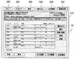
図3に示されるコピー画面210は、本発明の第1の表示画面に相当する画面であり、画面の上部に位置するコピーキー200に対応している。画面の上部には、該コピーキー200、スキャナーキー300、保存キー400、読み出しキー500、JOB管理キー600、機械状態キー700が並列して表示されており、該キーの押し下げによって関連する表示画面に遷移するように構成されている。なお、これらのキーの動作はそれぞれ独立して制御可能になっており、表示されている表示画面に拘わらず、各キーを選択してそれぞれのキーに関連する表示画面を表示させて動作させることが可能である。また、現表示画面によっては上記キーの選択を不可とする場合があっても、現表示画面を閉じることを可能にし、その後、各指示部の選択が可能になる。
なお、前記機械状態キー700は本願発明の第2の表示画面に関連付けられ、JOB管理キー600は、本願発明の第3の表示画面に関連付けられており、これらのキーは各表示画面を表示選択する指示部に相当する。
Next, a display screen displayed on the
A
The
第1の表示画面は、コピー画面であり、各種の動作条件の設定入力が可能になっている。例えば、原稿設定、画質設定、倍率設定、応用設定、出力設定、両面設定、用紙予約設定などの入力を行うことができる。メッセージ欄211には、コピー予約が可能であることが表示されている。メッセージ欄211の下方には、予約JOB数欄212が設けられており、この図では、JOBが既に5ジョブ登録されていることが示されている。そして、この画面では、入力を終了することで設定情報が不揮発メモリ115に記憶管理されてジョブ予約がされる。すなわち、この画面は本願発明のジョブ予約手段としても機能する。
The first display screen is a copy screen, and various operation condition settings can be input. For example, input such as document setting, image quality setting, magnification setting, application setting, output setting, duplex setting, and paper reservation setting can be performed. The
上記第1の表示画面では、原稿読込キー213を押すことで読み取り動作が実行される。該動作では、読み取り手段によって自動原稿給紙装置(ADF)123にセットされた原稿やプラテンガラス124に載置された原稿の読み取りがなされる。
読み込み動作開始と同時に図4に示す設定内容表示画面220を表示する。該設定内容表示画面220は、本願発明の第1の表示画面に含まれるものである。また、この画面においても画面の上部に各表示画面を選択可能とするコピーキー200、スキャナーキー300、保存キー400、読み出しキー500、JOB管理キー600、機械状態キー700が並列して表示されている。なお、設定内容表示画面220では、後述するデフォルト画面に依って表示内容が相違している。すなわち、デフォルト画面設定が前記したコピー画面の場合、設定内容表示画面220にJOB進行状況画面230を重ねて表示している(図4(a))。該画面は、消去が可能になる閉じるキー231を有しており、操作者は所望により、該閉じるキー231を押してJOB進行状況画面230を消去して新規JOBの予約が可能なコピー画面210が表示される。なお、上記閉じるキー231の操作が無い場合は、設定内容表示画面230で表示されているJOBの出力完了に従って画面を閉じてコピー画面に遷移する。
On the first display screen, the reading operation is executed by pressing the
Simultaneously with the start of the reading operation, the setting
一方、デフォルト画面設定が前記コピー画面以外では、設定内容表示画面220にコピー予約を継続するかしないかを選択可能な選択表示画面240を重ねて表示する(図4(b))。該選択表示画面240も本願発明の第1の表示画面に含まれ、コピー予約を継続する/しないの選択手段として機能する。選択表示画面240には予約を継続することに関し、YESキー241とNOキー242とを有しており、継続YESキー241が押されると選択表示画面240が消去されてコピー画面210に遷移する。一方、継続NOキー242が押されるとデフォルト画面に遷移する。キー操作がない場合は、設定内容表示画面220で表示されているJOBの出力完了に従って画面を閉じてデフォルト画面に遷移する。
On the other hand, when the default screen setting is other than the copy screen, a
次に、図5は、複数のJOBの状態を表示して管理するJOB管理画面610を表示するものであり、本願発明の第3の表示画面に相当する。該表示画面においても、画面の上部に各表示画面を選択可能とするコピーキー200、スキャナーキー300、保存キー400、読み出しキー500、JOB管理キー600、機械状態キー700が並列して表示されており、各キーに対応する表示画面について独立して制御がなされている。該JOB管理画面610では、動作中JOBも含めたJOBリスト表示が可能になっており、さらに動作中JOBの停止、予約JOBの出力並び替え、保留指示、予約JOBの削除などが可能になっている。
Next, FIG. 5 displays a
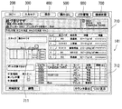
次に、図6は、機械状態画面710を示すものであり、本願発明の第2の表示画面に相当する。この表示画面においても画面の上部に各表示画面を選択可能とするコピーキー200、スキャナーキー300、保存キー400、読み出しキー500、JOB管理キー600、機械状態キー700が並列して表示されており、各キーに対応する表示画面について独立して制御がなされている。
該機械状態画面710では、JOBに依存しない状態の表示(例えばカセット、針無し、パンチ屑、裁断屑、トナー)や、異常発生表示、異常解除表示、異常解除後のリカバリースタート、動作中JOBのキャンセル、簡易機械図を用いた異常状態表示、スキャナ、プリンタ別状態表示が可能になっている。
Next, FIG. 6 shows a
On the
図中711は、読み取り手段に相当するスキャナの状態表示欄であり、712は画像形成手段に相当するプリンタの状態表示欄であり、それぞれ独立して表示可能となっている。なお、該機械状態画面710で中断ジョブが認識されている際に、スキャナとプリンタとで独立してリカバリ(再起動)することができる。例えば、スキャナとプリンタとで異なるJOBを実行している場合や同一のJOBを実行している際などに、リカバリ対象を特定して独立してリカバリすることで、操作や作業を円滑に行うことができる。
In the figure,
なお、各画面で表示される保存キー400を押すことで既に画像メモリ120に格納されている画像データがある場合には、HDD123やHDD164に格納することができる。また読み出しキー500を押すことでHDD123やHDD164に格納されている画像データを読み出して出力指示をしたり、予約ジョブとして登録することができる。
If there is image data already stored in the
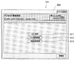
次に、図7は、デフォルト時に選択される表示画面を設定するデフォルト画面設定画面800を表示するものであり、デフォルト画面を選択する選択手段を構成している。
該画面は、サービスマンなどにより各種キーの組合せなどの特定された操作によって表示させることができる。
該設定画面800では、コピー画面キー801、ジョブ管理画面キー802、機械状態画面キー803が選択可能に表示されており、いずれかのキーを押すことで、デフォルト時に表示される画面をコピー画面210、ジョブ管理画面610、機械状態画面710の中から選定することができる。これにより操作者の使用方法などで最適なデフォルト画面が表示されるようにして操作性を高めることができる。
Next, FIG. 7 displays a default
The screen can be displayed by a specified operation such as a combination of various keys by a service person or the like.
In the
次に、JOBの設定入力中などに異常が発生した場合の表示画面制御について説明する。
コピー画面や設定内容表示画面の状態で異常が発生した場合の処理手順を図8のフローチャートに基づいて説明する。
Next, display screen control when an abnormality occurs during JOB setting input or the like will be described.
A processing procedure when an abnormality has occurred in the state of the copy screen or the setting content display screen will be described based on the flowchart of FIG.
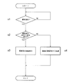
先ず、異常発生があったかどうかが判定される(ステップs1)。該判定は、前記した異常検知手段に基づいて行うことができる。異常発生が認められない場合には異常処理は待機される。一方、異常発生が認められる場合、異常発生JOBが現在表示されているJOBに係るものであるか否かの判定がなされる(ステップs2)。ここで、異常発生JOBが現在表示されているJOBである場合、この例では設定内容表示画面の状態であり、設定内容表示画面に異常発生画面を表示するとする(ステップs3)。図9は、設定内容表示画面220で表示JOBに異常が発生した場合に、異常発生画面750を領域を区分けして重ねて表示したものである。該異常発生画面750は、簡易機械図を用いた異常状態表示によって行われている。該異常発生画面750が表示されている画面では、指示部であるコピーキー200、スキャナーキー300、保存キー400、読み出しキー500、JOB管理キー600、機械状態キー700のキーを選択して押し下げることで異常解除が可能であり、例えばコピーキー200を押し下げてコピー画面210に遷移することができる。他の表示画面に遷移されて異常発生画面750が表示されていない状態では、機械状態キー700を赤色などの目立つ色で点滅させて異常発生通知表示を行う。
First, it is determined whether or not an abnormality has occurred (step s1). This determination can be made based on the above-described abnormality detection means. If no abnormality is found, the abnormality process is waited. On the other hand, when the occurrence of an abnormality is recognized, it is determined whether or not the abnormality occurrence JOB relates to the currently displayed JOB (step s2). Here, in the case where the abnormality occurrence JOB is the currently displayed JOB, in this example, the setting content display screen is displayed, and the abnormality occurrence screen is displayed on the setting content display screen (step s3). FIG. 9 shows an
一方、前記ステップs2で異常発生JOBが現在表示されているJOBと異なるものであると判定がなされた場合、ここでは、コピー画面で新規JOBの予約設定がなされていた状態であるとすると、図10に示すようにコピー画面210には異常発生画面は表示せず、機械状態キー700を赤色などの目立つ色で点滅させて異常発生通知表示を行う。操作者はそのままJOBの設定を続行することもできる。また、異常発生の内容を確認したい場合、機械状態キー700を押し下げると、機械状態画面710を表示するとともに異常発生画面760を表示する。また、ステップs2の判定時に機械状態画面710が表示されていた場合には、図11に示すように、該画面710に上記と同様に異常発生画面760を表示する。該機械状態画面710では、各表示画面と同様に画面の上部に各表示画面を選択可能とするコピーキー200、スキャナーキー300、保存キー400、読み出しキー500、JOB管理キー600、機械状態キー700が並列して表示されており、各キーを選択して各キーに対応した表示画面を表示させることができる。なお、図11に示すように、異常表示画面760には、簡易機械図を用いた異常状態表示によって行われている。該異常表示画面760には閉じるキー761が設けられており、該キー761を押し下げると異常表示画面760が閉じられて機械状態表示画面710が表示される。機械状態表示画面710には、中断しているジョブの中断詳細内容が表示されている。すなわち、前記した閉じるきー761は、本発明の詳細表示指示部に相当する。また機械状態表示画面710に確認キー715が設けられており、該確認キーを押し下げると再度上記異常表示画面760が表示される。すなわち、機械状態画面では、詳細表示と簡易表示とを任意に選択することができる。
異常が解除された場合には、異常表示画面750、760は閉じられてそれぞれの元画面が表示され、設定入力等を継続することができる。
On the other hand, if it is determined in step s2 that the abnormal job is different from the currently displayed job, it is assumed here that the reservation setting for the new job has been made on the copy screen. As shown in FIG. 10, an error occurrence screen is not displayed on the
When the abnormality is released, the abnormality display screens 750 and 760 are closed and the respective original screens are displayed, and setting input or the like can be continued.
以上本発明を上記実施形態に基づいて説明したが、本発明は上記説明に限定されるものではなく、本発明の範囲を逸脱しない限りにおいて変更が可能である。 Although the present invention has been described based on the above embodiment, the present invention is not limited to the above description and can be modified without departing from the scope of the present invention.
1 画像形成装置
50 ネットワーク
100 画像装置制御部
112 LANインターフェース
113 制御CPU
115 不揮発メモリ
120 画像メモリ
123 HDD
125 伸長IC
126 書き込み処理部
130 スキャナ部
140 操作部
141 タッチパネル
150 プリンタ部
160 画像処理手段
164 HDD
165 LANインターフェース
200 コピーキー
210 コピー画面
220 設定内容表示画面
300 スキャナーキー
400 保存キー
500 読み出しキー
600 JOB管理キー
610 JOB管理画面
700 機械状態キー
710 機械状態画面
750 異常発生画面
760 異常発生画面
DESCRIPTION OF
115
125 extension IC
126 Write processing unit 130 Scanner unit 140
165
Claims (17)
動作条件を表示するとともに該条件の設定及び実行入力が可能な第1の表示画面、装置の機械状態を管理する第2の表示画面、出力中及び出力予約されたジョブを管理する第3の表示画面の各々を表示可能であると共に、表示されている各表示画面に拘わらず、前記第1の表示画面を表示させる指示部、前記第2の表示画面を表示させる指示部、前記第3の表示画面を表示させる指示部を、前記各表示画面において表示する表示手段と、を備えることを特徴とする画像形成装置。 Image forming means for forming an image based on image information;
First display screen and displays the operating conditions can be set and executed input of the condition, a second display screen for managing a machine state of the device, the third display of managing jobs and output reserved in the output each with can be displayed to the screen, regardless of the display screen displayed, an instruction unit for displaying the first display screen, an instruction portion for displaying said second display screen, the third An image forming apparatus comprising: an instruction unit for displaying a display screen ; and display means for displaying on each display screen .
Priority Applications (1)
| Application Number | Priority Date | Filing Date | Title |
|---|---|---|---|
| JP2004203758A JP4730510B2 (en) | 2004-07-09 | 2004-07-09 | Image forming apparatus |
Applications Claiming Priority (1)
| Application Number | Priority Date | Filing Date | Title |
|---|---|---|---|
| JP2004203758A JP4730510B2 (en) | 2004-07-09 | 2004-07-09 | Image forming apparatus |
Publications (3)
| Publication Number | Publication Date |
|---|---|
| JP2006023669A JP2006023669A (en) | 2006-01-26 |
| JP2006023669A5 JP2006023669A5 (en) | 2007-02-22 |
| JP4730510B2 true JP4730510B2 (en) | 2011-07-20 |
Family
ID=35796954
Family Applications (1)
| Application Number | Title | Priority Date | Filing Date |
|---|---|---|---|
| JP2004203758A Expired - Fee Related JP4730510B2 (en) | 2004-07-09 | 2004-07-09 | Image forming apparatus |
Country Status (1)
| Country | Link |
|---|---|
| JP (1) | JP4730510B2 (en) |
Families Citing this family (7)
| Publication number | Priority date | Publication date | Assignee | Title |
|---|---|---|---|---|
| JP2007232908A (en) * | 2006-02-28 | 2007-09-13 | Kyocera Mita Corp | Image forming apparatus |
| US7757131B2 (en) | 2006-02-28 | 2010-07-13 | Kyocera Mita Corporation | Image forming apparatus |
| JP4830713B2 (en) * | 2006-08-16 | 2011-12-07 | 富士ゼロックス株式会社 | Instruction information processing apparatus and control method thereof |
| JP4727752B2 (en) * | 2010-02-02 | 2011-07-20 | 京セラミタ株式会社 | Image forming apparatus |
| JP2018128530A (en) * | 2017-02-07 | 2018-08-16 | 株式会社東芝 | Image processing apparatus and information providing method |
| JP7238425B2 (en) * | 2019-01-24 | 2023-03-14 | 富士フイルムビジネスイノベーション株式会社 | Information processing device and program |
| JP7286366B2 (en) | 2019-03-26 | 2023-06-05 | キヤノン株式会社 | Image forming apparatus and its control method |
Citations (5)
| Publication number | Priority date | Publication date | Assignee | Title |
|---|---|---|---|---|
| JP2001356853A (en) * | 2000-06-12 | 2001-12-26 | Canon Inc | Image processor and state display control method of the same |
| JP2002344674A (en) * | 2001-05-18 | 2002-11-29 | Sharp Corp | Operation panel and image forming device provided with it |
| JP2003101712A (en) * | 2001-09-25 | 2003-04-04 | Kyocera Mita Corp | Composite device |
| JP2003177852A (en) * | 2001-12-07 | 2003-06-27 | Konica Corp | Operation display part control method for information processor and information processor |
| JP2003298783A (en) * | 2002-03-29 | 2003-10-17 | Ricoh Co Ltd | Image forming apparatus |
Family Cites Families (4)
| Publication number | Priority date | Publication date | Assignee | Title |
|---|---|---|---|---|
| JP3405880B2 (en) * | 1996-01-26 | 2003-05-12 | 株式会社リコー | Digital copier |
| JP3486502B2 (en) * | 1996-02-22 | 2004-01-13 | 株式会社リコー | Digital copier |
| JP3889135B2 (en) * | 1996-11-28 | 2007-03-07 | 株式会社東芝 | Image forming apparatus and image forming method |
| JP3544127B2 (en) * | 1997-10-24 | 2004-07-21 | キヤノン株式会社 | Image forming apparatus and control method of image forming apparatus |
-
2004
- 2004-07-09 JP JP2004203758A patent/JP4730510B2/en not_active Expired - Fee Related
Patent Citations (5)
| Publication number | Priority date | Publication date | Assignee | Title |
|---|---|---|---|---|
| JP2001356853A (en) * | 2000-06-12 | 2001-12-26 | Canon Inc | Image processor and state display control method of the same |
| JP2002344674A (en) * | 2001-05-18 | 2002-11-29 | Sharp Corp | Operation panel and image forming device provided with it |
| JP2003101712A (en) * | 2001-09-25 | 2003-04-04 | Kyocera Mita Corp | Composite device |
| JP2003177852A (en) * | 2001-12-07 | 2003-06-27 | Konica Corp | Operation display part control method for information processor and information processor |
| JP2003298783A (en) * | 2002-03-29 | 2003-10-17 | Ricoh Co Ltd | Image forming apparatus |
Also Published As
| Publication number | Publication date |
|---|---|
| JP2006023669A (en) | 2006-01-26 |
Similar Documents
| Publication | Publication Date | Title |
|---|---|---|
| US8836965B2 (en) | Printing system, job processing method, storage medium, and printing apparatus | |
| JP4125269B2 (en) | Job processing system and control method thereof | |
| JP2006308913A (en) | Image forming apparatus, image forming apparatus control method and recording medium | |
| JP5103307B2 (en) | Image forming apparatus | |
| JP4730510B2 (en) | Image forming apparatus | |
| JP5245726B2 (en) | Image forming apparatus | |
| JP2008177817A (en) | Image forming device | |
| JP5716729B2 (en) | Image forming apparatus, program, and job execution control method | |
| JP2006197053A (en) | Image forming apparatus | |
| JP4111972B2 (en) | Image processing device | |
| US20120057203A1 (en) | Printing system, printing system control method, and storage medium | |
| JP2006174064A (en) | Image forming apparatus | |
| JP2010158777A (en) | Image forming device, terminal device and printing system including those devices | |
| JP2006224398A (en) | Printer device | |
| JP2008022456A (en) | Image processing device and image processing control method | |
| JP5376170B2 (en) | Image formation control unit, image forming apparatus, display device, and display program | |
| JP7022353B2 (en) | Image forming device, control method of image forming device, and program | |
| JP5509938B2 (en) | Image forming apparatus and information display method | |
| JP2008028705A (en) | Maintenance system and image processor | |
| JP2008279699A (en) | Image formation device and control method of the same | |
| JP2008049509A (en) | Image forming apparatus | |
| JP2007336155A (en) | Image forming apparatus | |
| JP6379053B2 (en) | Image processing device | |
| JP4393536B2 (en) | Image forming apparatus and control method thereof | |
| JP2010139531A (en) | Image forming apparatus |
Legal Events
| Date | Code | Title | Description |
|---|---|---|---|
| A521 | Written amendment |
Free format text: JAPANESE INTERMEDIATE CODE: A523 Effective date: 20061215 |
|
| A621 | Written request for application examination |
Free format text: JAPANESE INTERMEDIATE CODE: A621 Effective date: 20061215 |
|
| A977 | Report on retrieval |
Free format text: JAPANESE INTERMEDIATE CODE: A971007 Effective date: 20100114 |
|
| A131 | Notification of reasons for refusal |
Free format text: JAPANESE INTERMEDIATE CODE: A131 Effective date: 20100126 |
|
| A521 | Written amendment |
Free format text: JAPANESE INTERMEDIATE CODE: A523 Effective date: 20100329 |
|
| A131 | Notification of reasons for refusal |
Free format text: JAPANESE INTERMEDIATE CODE: A131 Effective date: 20100602 |
|
| A131 | Notification of reasons for refusal |
Free format text: JAPANESE INTERMEDIATE CODE: A131 Effective date: 20101020 |
|
| A01 | Written decision to grant a patent or to grant a registration (utility model) |
Free format text: JAPANESE INTERMEDIATE CODE: A01 Effective date: 20110323 |
|
| A61 | First payment of annual fees (during grant procedure) |
Free format text: JAPANESE INTERMEDIATE CODE: A61 Effective date: 20110405 |
|
| FPAY | Renewal fee payment (event date is renewal date of database) |
Free format text: PAYMENT UNTIL: 20140428 Year of fee payment: 3 |
|
| R150 | Certificate of patent or registration of utility model |
Free format text: JAPANESE INTERMEDIATE CODE: R150 |
|
| S111 | Request for change of ownership or part of ownership |
Free format text: JAPANESE INTERMEDIATE CODE: R313111 |
|
| R350 | Written notification of registration of transfer |
Free format text: JAPANESE INTERMEDIATE CODE: R350 |
|
| LAPS | Cancellation because of no payment of annual fees |