JP4728362B2 - Node identifier setting method for communication system - Google Patents
Node identifier setting method for communication system Download PDFInfo
- Publication number
- JP4728362B2 JP4728362B2 JP2008080249A JP2008080249A JP4728362B2 JP 4728362 B2 JP4728362 B2 JP 4728362B2 JP 2008080249 A JP2008080249 A JP 2008080249A JP 2008080249 A JP2008080249 A JP 2008080249A JP 4728362 B2 JP4728362 B2 JP 4728362B2
- Authority
- JP
- Japan
- Prior art keywords
- node
- slave
- setting
- node identifier
- start signal
- Prior art date
- Legal status (The legal status is an assumption and is not a legal conclusion. Google has not performed a legal analysis and makes no representation as to the accuracy of the status listed.)
- Expired - Fee Related
Links
Images


Landscapes
- Small-Scale Networks (AREA)
Description
この発明は、マスタノードとスレーブノードとが存在する通信システムのスレーブノードにノード識別子を割り当てる通信システムのノード識別子設定方法に係り、特に接続されるスレーブノードの個数が変化しても、マスタノードの設定を変更することなくスレーブノードへのノード識別子を設定できるものである。 The present invention relates to a node identifier setting method of a communication system that assigns a node identifier to a slave node of a communication system in which a master node and a slave node exist, and in particular, even if the number of connected slave nodes changes, The node identifier to the slave node can be set without changing the setting.
従来の通信システムのノード識別子設定方法としては、通信システム内のスレーブノードにノード識別子を割り当てる種々の方法が示されている。例えば、通信バス上に接続されるノードにノード識別子を割り当てる方法として、マスタ(ノード識別子を決める側を指す。以下においても同様であるためこの説明は適宜省略する。)ノードとスレーブ(ノード識別子が決まっていない側を指す。以下においても同様であるためこの説明は適宜省略する。)ノードとがあらかじめ同じノード識別子リストを保有する。次に、スレーブノードは、保有するノード識別子リストから一つのノード識別子を選択する。 As a node identifier setting method of a conventional communication system, various methods for assigning a node identifier to a slave node in the communication system are shown. For example, as a method of assigning a node identifier to a node connected on a communication bus, a master (refers to a side that determines a node identifier. The same applies to the following, so this description will be omitted as appropriate) a node and a slave (the node identifier is (This is the same in the following, and this description will be omitted as appropriate.) The node has the same node identifier list in advance. Next, the slave node selects one node identifier from the node identifier list that it holds.
次に、マスタノードは、保有するノード識別子リストから一つのノード識別子を選択し、すべてのノードに対して送信する。次に、スレーブノードは自身が選択したノード識別子と同じものが送信されれば応答する。次に、スレーブノードは、他のスレーブノードからの応答を監視し、応答したスレーブノードが自身だけなら、そのノード識別子を自スレーブノードの固有のノード識別子として確定する。次に、応答したスレーブノードが他にもあれば、スレーブノードは別のノード識別子を選択しなおす。次に、マスタノードは保有するノード識別子リストの順に送信し、すべてのスレーブノードのノード識別子を決めていく(例えば、特許文献1参照)。 Next, the master node selects one node identifier from the node identifier list that it holds and transmits it to all nodes. Next, the slave node responds if the same node identifier selected by itself is transmitted. Next, the slave node monitors responses from other slave nodes, and if the responding slave node is the only one, it determines the node identifier as a unique node identifier of the own slave node. Next, if there are other slave nodes that responded, the slave node reselects another node identifier. Next, the master node transmits in the order of the node identifier list that it holds, and determines the node identifiers of all the slave nodes (see, for example, Patent Document 1).
また、他の通信バス上に接続されるノードにノード識別子を割り当てる通信システムのノード識別子設定方法としては、マスタノードは要求メッセージを送信し、要求メッセージを受信したスレーブノードは、ランダム変数に基づき設定した監視時間の間、応答メッセージの送信を待機する。次に、スレーブノードは監視時間中に他のスレーブノードから応答メッセージが送信されなかったとき、受信したノード識別子を自スレーブノードの固有のノード識別子として設定し、応答メッセージを送信する(例えば、特許文献2参照)。 As a node identifier setting method of a communication system that assigns a node identifier to a node connected to another communication bus, a master node transmits a request message, and a slave node that receives the request message sets based on a random variable. During the monitoring time, it waits for a response message to be sent. Next, when a response message is not transmitted from another slave node during the monitoring time, the slave node sets the received node identifier as a unique node identifier of the slave node, and transmits the response message (for example, patent Reference 2).
この発明は、1つのマスタノードと1つまたは複数のスレーブノードとが通信バスにて接続されるとともに、マスタノードと1つまたは複数のスレーブノードとがノード識別子設定状況を通知する通知線にてデイジーチェーン接続でかつリング状に接続されている通信システムのノード識別子設定方法であって、
マスタノードが、通知線において後に接続されているスレーブノードに設定開始信号を出力し、通知線から設定開始信号を入力したスレーブノードは、通信バス上へのメッセージ送信を停止するとともに、通知線において後に接続されているスレーブノードまたはマスタノードに設定開始信号を出力し、マスタノードは、通知線において前に接続されているスレーブノードから設定開始信号を受け取ると、再度、通知線において後に接続されているスレーブノードに再度設定開始信号を出力して、当該スレーブノードにノード識別子の設定を行うための要求メッセージを通信バス上に送信する第1ステップと、
通知線から設定開始信号を入力したスレーブノードは、通信バス上に流れている要求メッセージを受信し、要求メッセージで要求されたノード識別子を自スレーブノードの固有のノード識別子として設定し、通信バス上へノード識別子設定を行ったとの応答メッセージを送信するとともに、通知線において後に接続されているスレーブノードまたはマスタノードに設定開始信号を出力する第2ステップと、
マスタノードが、応答メッセージを受信し、かつ、通知線において前に接続されているスレーブノードから設定開始信号を受け取らなければ、別の要求メッセージを通信バス上に送信して第2ステップへ戻り、
マスタノードが、応答メッセージを受信し、かつ、通知線において前に接続されているスレーブノードから設定開始信号を受け取るとノード識別子設定を終了する第3ステップとを備えたものである。
In the present invention, one master node and one or a plurality of slave nodes are connected by a communication bus, and the master node and one or a plurality of slave nodes use a notification line for notifying a node identifier setting status. A node identifier setting method for a communication system connected in a ring shape with a daisy chain connection,
The master node outputs a setting start signal to a slave node connected later on the notification line, and the slave node that has input the setting start signal from the notification line stops message transmission on the communication bus and When a setting start signal is output to a slave node or a master node that is connected later, and the master node receives a setting start signal from a slave node that is connected before on the notification line, the master node is again connected later on the notification line. A first step of outputting a setting start signal to the slave node again and transmitting a request message for setting the node identifier to the slave node on the communication bus;
The slave node that has input the setting start signal from the notification line receives the request message flowing on the communication bus, sets the node identifier requested in the request message as a unique node identifier of its own slave node, A second step of transmitting a response message indicating that the node identifier has been set to the node and outputting a setting start signal to a slave node or a master node connected later on the notification line;
If the master node receives a response message and does not receive a setup start signal from a previously connected slave node on the notification line, it sends another request message on the communication bus and returns to the second step;
The master node includes a third step of receiving the response message and ending the node identifier setting when receiving the setting start signal from the slave node previously connected in the notification line.
この発明の通信システムのノード識別子設定方法は、1つのマスタノードと1つまたは複数のスレーブノードとが通信バスにて接続されるとともに、マスタノードと1つまたは複数のスレーブノードとがノード識別子設定状況を通知する通知線にてデイジーチェーン接続でかつリング状に接続されている通信システムのノード識別子設定方法であって、
マスタノードが、通知線において後に接続されているスレーブノードに設定開始信号を出力し、通知線から設定開始信号を入力したスレーブノードは、通信バス上へのメッセージ送信を停止するとともに、通知線において後に接続されているスレーブノードまたはマスタノードに設定開始信号を出力し、マスタノードは、通知線において前に接続されているスレーブノードから設定開始信号を受け取ると、再度、通知線において後に接続されているスレーブノードに再度設定開始信号を出力して、当該スレーブノードにノード識別子の設定を行うための要求メッセージを通信バス上に送信する第1ステップと、
通知線から設定開始信号を入力したスレーブノードは、通信バス上に流れている要求メッセージを受信し、要求メッセージで要求されたノード識別子を自スレーブノードの固有のノード識別子として設定し、通信バス上へノード識別子設定を行ったとの応答メッセージを送信するとともに、通知線において後に接続されているスレーブノードまたはマスタノードに設定開始信号を出力する第2ステップと、
マスタノードが、応答メッセージを受信し、かつ、通知線において前に接続されているスレーブノードから設定開始信号を受け取らなければ、別の要求メッセージを通信バス上に送信して第2ステップへ戻り、
マスタノードが、応答メッセージを受信し、かつ、通知線において前に接続されているスレーブノードから設定開始信号を受け取るとノード識別子設定を終了する第3ステップとを備えたので、マスタノードの設定を変更することなく、全てのスレーブノードへノード識別子を設定することができ、さらに、ノード識別子設定の時間を短縮することができる。
In the node identifier setting method of the communication system according to the present invention, one master node and one or a plurality of slave nodes are connected via a communication bus, and the master node and one or a plurality of slave nodes are set to a node identifier. A node identifier setting method for a communication system that is connected in a ring shape in a daisy chain connection with a notification line that notifies the situation,
The master node outputs a setting start signal to a slave node connected later on the notification line, and the slave node that has input the setting start signal from the notification line stops message transmission on the communication bus and When a setting start signal is output to a slave node or a master node that is connected later, and the master node receives a setting start signal from a slave node that is connected before on the notification line, the master node is again connected later on the notification line. A first step of outputting a setting start signal to the slave node again and transmitting a request message for setting the node identifier to the slave node on the communication bus;
The slave node that has input the setting start signal from the notification line receives the request message flowing on the communication bus, sets the node identifier requested in the request message as a unique node identifier of its own slave node, A second step of transmitting a response message indicating that the node identifier has been set to the node and outputting a setting start signal to a slave node or a master node connected later on the notification line;
If the master node receives a response message and does not receive a setup start signal from a previously connected slave node on the notification line, it sends another request message on the communication bus and returns to the second step;
When the master node receives the response message and receives the setting start signal from the slave node previously connected in the notification line, the master node includes a third step for ending the node identifier setting. Node identifiers can be set for all slave nodes without change, and the node identifier setting time can be reduced.
この発明は、1つのマスタノードと1つまたは複数のスレーブノードとが通信バスにて接続されるとともに、マスタノードと1つまたは複数のスレーブノードとがノード識別子設定状況を通知する通知線にてデイジーチェーン接続でかつリング状に接続されている通信システムのノード識別子設定方法であって、
マスタノードが、通知線において後に接続されているスレーブノードに設定開始信号を出力して、当該スレーブノードにノード識別子の設定を行うための要求メッセージを通信バス上に送信する第1ステップと、
通知線から設定開始信号を入力したスレーブノードは、通信バス上に流れている要求メッセージを受信し、要求メッセージで要求されたノード識別子を自スレーブノードの固有のノード識別子として設定し、通信バス上へノード識別子設定を行ったとの応答メッセージを送信するとともに、通知線において後に接続されているスレーブノードまたはマスタノードに設定開始信号を出力する第2ステップと、
マスタノードが、応答メッセージを受信し、かつ、通知線において前に接続されているスレーブノードから設定開始信号を受け取らなければ、別の要求メッセージを通信バス上に送信して第2ステップへ戻り、
マスタノードが、応答メッセージを受信し、かつ、通知線において前に接続されているスレーブノードから設定開始信号を受け取るとノード識別子設定を終了する第3ステップとを備えたものである。
In the present invention, one master node and one or a plurality of slave nodes are connected by a communication bus, and the master node and one or a plurality of slave nodes use a notification line for notifying a node identifier setting status. A node identifier setting method for a communication system connected in a ring shape with a daisy chain connection,
A first step in which a master node outputs a setting start signal to a slave node connected later on a notification line and transmits a request message for setting a node identifier to the slave node on the communication bus;
The slave node that has input the setting start signal from the notification line receives the request message flowing on the communication bus, sets the node identifier requested in the request message as a unique node identifier of its own slave node, A second step of transmitting a response message indicating that the node identifier has been set to the node and outputting a setting start signal to a slave node or a master node connected later on the notification line;
If the master node receives a response message and does not receive a setup start signal from a previously connected slave node on the notification line, it sends another request message on the communication bus and returns to the second step;
The master node includes a third step of receiving the response message and ending the node identifier setting when receiving the setting start signal from the slave node previously connected in the notification line.
この発明の通信システムのノード識別子設定方法は、1つのマスタノードと1つまたは複数のスレーブノードとが通信バスにて接続されるとともに、マスタノードと1つまたは複数のスレーブノードとがノード識別子設定状況を通知する通知線にてデイジーチェーン接続でかつリング状に接続されている通信システムのノード識別子設定方法であって、
マスタノードが、通知線において後に接続されているスレーブノードに設定開始信号を出力して、当該スレーブノードにノード識別子の設定を行うための要求メッセージを通信バス上に送信する第1ステップと、
通知線から設定開始信号を入力したスレーブノードは、通信バス上に流れている要求メッセージを受信し、要求メッセージで要求されたノード識別子を自スレーブノードの固有のノード識別子として設定し、通信バス上へノード識別子設定を行ったとの応答メッセージを送信するとともに、通知線において後に接続されているスレーブノードまたはマスタノードに設定開始信号を出力する第2ステップと、
マスタノードが、応答メッセージを受信し、かつ、通知線において前に接続されているスレーブノードから設定開始信号を受け取らなければ、別の要求メッセージを通信バス上に送信して第2ステップへ戻り、
マスタノードが、応答メッセージを受信し、かつ、通知線において前に接続されているスレーブノードから設定開始信号を受け取るとノード識別子設定を終了する第3ステップとを備えたので、マスタノードの設定を変更することなく、全てのスレーブノードへノード識別子を設定することができ、さらに、ノード識別子設定の時間を短縮することができる。
In the node identifier setting method of the communication system according to the present invention, one master node and one or a plurality of slave nodes are connected via a communication bus, and the master node and one or a plurality of slave nodes are set to a node identifier. A node identifier setting method for a communication system that is connected in a ring shape in a daisy chain connection with a notification line that notifies the situation,
A first step in which a master node outputs a setting start signal to a slave node connected later on a notification line and transmits a request message for setting a node identifier to the slave node on the communication bus;
The slave node that has input the setting start signal from the notification line receives the request message flowing on the communication bus, sets the node identifier requested in the request message as a unique node identifier of its own slave node, A second step of transmitting a response message indicating that the node identifier has been set to the node and outputting a setting start signal to a slave node or a master node connected later on the notification line;
If the master node receives a response message and does not receive a setup start signal from a previously connected slave node on the notification line, it sends another request message on the communication bus and returns to the second step;
When the master node receives the response message and receives the setting start signal from the slave node previously connected in the notification line, the master node includes a third step for ending the node identifier setting. Node identifiers can be set for all slave nodes without change, and the node identifier setting time can be reduced.
実施の形態1.
以下、この発明の実施の形態について説明する。図1はこの発明の実施の形態1における通信システムの構成を示す図、図2は図1に示した通信システムのノード識別子設定方法を説明するためのフローチャート、図3は図2に示した通信システムのノード識別子設定方法におけるマスタノードの動作を説明するためのフローチャート、図4は図2に示した通信システムのノード識別子設定方法におけるスレーブノードの動作を説明するためのフローチャートである。
Embodiment 1 FIG.
Embodiments of the present invention will be described below. 1 is a diagram showing a configuration of a communication system according to Embodiment 1 of the present invention, FIG. 2 is a flowchart for explaining a node identifier setting method of the communication system shown in FIG. 1, and FIG. 3 is a communication shown in FIG. 4 is a flowchart for explaining the operation of the master node in the node identifier setting method of the system, and FIG. 4 is a flowchart for explaining the operation of the slave node in the node identifier setting method of the communication system shown in FIG.
図のおいて、マスタノード21と、スレーブノードA22と、スレーブノードB23と、スレーブノードC24とが通信バス11にそれぞれ接続されネットワークが構成されている。また、マスタノード21と、スレーブノードA22と、スレーブノードB23と、スレーブノードC24とは、例えばデジタル入出力線にて形成されているノード識別子設定の状況を通知する通知線12にて、デジタス出力32、34、36、38およびデジタル入力31、33、35、37が、デイジーチェーン接続に、かつ、リング状に接続されている。尚、図示したもの以外にも、ネットワークの通信システムに必要な装置・構成を有するが、この発明において直接関与しないため図示を省略する。
In the figure, a
上記のように構成された実施の形態1の通信システムのノード識別子設定方法について図2ないし図4のフローチャートに基づいて説明する。まず、電源の投入もしくはリセット等で通信システムが初期化されると、ノード識別子設定が開始される。次に、マスタノード21がデジタル出力32の出力値を現在の値から論理反転して出力することにより、通知線12から設定開始信号を出力する。そして、マスタノード21は、通知線12において後に接続されているスレーブノードA22にノード識別子の設定を行うための要求メッセージを通信バス11上へ送信する(図2のステップS11)。
A node identifier setting method of the communication system of the first embodiment configured as described above will be described based on the flowcharts of FIGS. First, when the communication system is initialized by power-on or reset, node identifier setting is started. Next, the
次に、デジタル入力33の入力値が論理反転したことを検出することにより、通知線12から設定開始信号を入力したスレーブノードA22は、通信バス11上に流れている要求メッセージを受信する。そして、要求メッセージにて要求されたノード識別子を自スレーブノードA22の固有のノード識別子として設定する。そして、ノード識別子の設定を行ったとの応答メッセージを通信バス11上へ送信する。そして、デジタル出力34の出力値を現在の値から論理反転して出力することにより、スレーブノードA22は設定開始信号を通知線12から出力する(図2のステップS12)。このように、ノード識別子を設定されたスレーブノードA22は通常状態となり、通信バス11にて通常の通信を開始する。
Next, by detecting that the input value of the digital input 33 is logically inverted, the
尚、この要求メッセージおよび応答メッセージは、マスタノードおよびスレーブノードの受信もれを防止するために、複数回送信してもよいことは言うまでもない。また、要求メッセージと応答メッセージとは、通信バス11上に流れている通常の通信メッセージとは異なる構成にて形成する。このように形成することにより、通信バス11上に流れている他の通信メッセージとの区別を容易に行うできる。そしてこのことにより、誤った通信メッセージをノード識別子設定に用いられることが防止できる。
Needless to say, the request message and the response message may be transmitted a plurality of times in order to prevent the master node and the slave node from leaking. In addition, the request message and the response message are formed with a configuration different from that of a normal communication message flowing on the
次に、マスタノード21がスレーブノードA22から送信された応答メッセージを通信バス11から受信する(図2のステップS13)。次に、マスタノード21は通知線12において前に接続されているスレーブノードC24からデジタル入力31の入力値が論理反転したか否かを判断することにより、設定開始信号が入力されたか否かを判断する。このことより、全てのスレーブノードA22、B23、C24へノード識別子設定が終了したか否かを判定することができる(図2のステップS14)。そして、マスタノード21がデジタル入力31の入力値に変化がないと判断する、すなわち設定開始信号が入力されていないと判断する(NO)と、別の要求メッセージを通信バス11上へ送信する(図2のステップS15)。次に、ステップS12へ戻り、上記に示した動作を繰り返す。
Next, the
そして、デジタル入力35の入力値が論理反転したことを検出することにより、スレーブノードB23が上記に示したスレーブノードA22と同様の動作を行い、自スレーブノードのノード識別子に設定し、応答メッセージを通信バス11上へ送信すると同時に、デジタル出力36の出力値を現在の値から論理反転して出力することにより、スレーブノードB23は設定開始信号を出力する。このように、ノード識別子を設定されたスレーブノードB23は通常状態となり、通信バス11にて通常の通信を開始する。
Then, by detecting that the input value of the
そして、再びステップS12に戻り、デジタル入力37の入力値が理論反転したことを検出することにより、スレーブノードC24が上記に示したスレーブノードA22、B23と同様の動作を行い、自スレーブノードC24のノード識別子に設定し、応答メッセージを通信バス11上へ送信すると同時に、デジタル出力38の出力値を現在の値から論理反転して出力することにより、スレーブノードC24は設定開始信号を出力する。このように、ノード識別子を設定されたスレーブノードC24は通常状態となり、通信バス11にて通常の通信を開始する。
Then, returning to step S12 again, by detecting that the input value of the
次に、マスタノード21はスレーブノードC24から送信された応答メッセージを受信する(図2のステップS13)。次に、マスタノード21は通知線12において前に接続されているスレーブノードC24からデジタル入力31の入力値が論理反転したと判断することにより、設定開始信号が入力されたと判断し(YES)、全てのスレーブノードA22、B23、C24へノード識別子が設定されたと判断し、ノード識別子の設定を終了する。
Next, the
このようにして、図1に示したネットワークにおいて全てのスレーブノードA22、B23、C24に固有のノード識別子を割り当てることができる。尚、ここでは便宜上、3つのスレーブノードを例に説明したが、これに限られることはなく、1つまたは複数のスレーブノードが配設されていても同様に行うことができることは言うまでもない。 In this way, unique node identifiers can be assigned to all the slave nodes A22, B23, and C24 in the network shown in FIG. For convenience, three slave nodes have been described as an example here, but the present invention is not limited to this, and it goes without saying that the same can be done even if one or more slave nodes are provided.
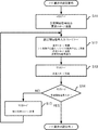
次に、マスタノード21が、いずれかのスレーブノードA22、B23、C24からの応答メッセージを第1の所定期間が経過しても受信できない場合について、図3の先に示した通信システムのノード識別子設定方法におけるマスタノードの動作を示したフローチャートに基づいて説明する。まず、マスタノード21がデジタル出力32から設定開始信号を出力するとともに、要求メッセージを通信バス11上へ送信する(図3のステップS21、図2に示したステップS11と同一の動作である)。次に、いずれかのスレーブノードA22、B23、C24からの応答メッセージが受信されたか否かを判断する(図3のステップS22)。このことにより、要求メッセージに対する応答があったか否かを判定することができる。
Next, in the case where the
次に、要求メッセージに対する応答がないと判断される(NO)と、要求メッセージを送信してから予め設定された第1の所定期間が経過したか否かを判断する(図3のステップS23)。次に、第1の所定期間が経過していなければ(NO)、再びステップS22に戻って上記に示した動作と同様の動作を行うことにより、いずれかのスレーブノードA22、B23、C24からの応答メッセージが送信されてくるのを待つ。尚、ここにおいて設定されている第1の所定期間とは、スレーブノードが要求メッセージを受信してから応答メッセージを送信するまでの最大期間よりも長い期間で、かつ、これ以上はかかることがないだろうと考えられる期間より短い期間において設定されているものである。 Next, when it is determined that there is no response to the request message (NO), it is determined whether or not a first predetermined period set in advance has elapsed since the request message was transmitted (step S23 in FIG. 3). . Next, if the first predetermined period has not elapsed (NO), the process returns to step S22 again, and the same operation as the above operation is performed, so that one of the slave nodes A22, B23, C24 Wait for a response message to be sent. Note that the first predetermined period set here is a period longer than the maximum period from when the slave node receives the request message until it transmits the response message, and it does not take any longer. It is set in a period shorter than the period considered to be.
次に、ステップS23にて第1の所定期間が経過したと判断される(YES)と、何らかの通信異常などが発生して、いずれかのスレーブノードA22、B23、C24にノード識別子を正常に設定できなかったもの判断できる。そして、後述するステップS26からノード識別子の設定回数を表すカウンタ値を入力し、何番目のスレーブノードから応答メッセージが送信されなかったのかを記録する(図3のステップS24)。次に、再びステップS21へ戻り、上記に示した動作と同様の動作を繰り返す。 Next, when it is determined in step S23 that the first predetermined period has elapsed (YES), some kind of communication abnormality has occurred, and the node identifier is normally set to any of the slave nodes A22, B23, C24. Can judge what could not be done. Then, a counter value indicating the number of times the node identifier is set is input from step S26, which will be described later, and the number of slave nodes from which the response message has not been transmitted is recorded (step S24 in FIG. 3). Next, the process returns to step S21 again, and the same operation as the operation described above is repeated.
次に、ステップS22にて、要求メッセージに対する応答があったと判断される(YES)と、マスタノード21は通知線12において前に接続されているスレーブノードC24から設定開始信号が入力されたか否かを判断する(図3のステップS25、図2のステップS14と同一の動作である。)。そして、マスタノード21はデジタル入力31の入力値に変化がないと判断される、すなわち設定開始信号が入力されていない(NO)と判断されると、ノード識別子の設定回数カウンタ値をインクリメント(つまり+1)する(図3のステップS26)。次に、別の要求メッセージを通信バス11上へ送信し(図3のステップS27、図2のステップS15と同一の動作である。)、ステップS22へ戻り、上記に示した動作を繰り返す。また、ステップS25において、マスタノード21は通知線12において前に接続されているスレーブノードC24から設定開始信号が入力されたと判断すると、全てのスレーブノードA22、B23、C24へノード識別子が設定されたと判断し、ノード識別子設定を終了する。
Next, when it is determined in step S22 that there is a response to the request message (YES), the
このようにして、図1に示したネットワークにおいて、もし、いずれかのスレーブノードA22、B23、C24からの応答メッセージが第1の所定期間経過しても送信されないと、再度、ノード識別子設定を開始するとともに、何番目のスレーブノードから応答がないのかを記録することができる。 In this way, in the network shown in FIG. 1, if the response message from any of the slave nodes A22, B23, C24 is not transmitted even after the first predetermined period, the node identifier setting is started again. At the same time, it is possible to record which slave node does not respond.
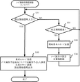
次に、いずれかのスレーブノードA22、B23、C24が自スレーブノードのノード識別子が登録されていない状態で、第2の所定期間が経過してもノード識別子設定が行われない場合について、図4の先に示した通信システムのノード識別子設定方法におけるスレーブノードの動作を示したフローチャートに基づいて説明する。尚、この処理は各スレーブノードA22、B23、C24がそれぞれ独立して実行するものである。まず、各スレーブノードA22、B23、C24はデジタル入力33、35、37から設定開始信号が入力されたか否かにより、マスタノード21からの要求メッセージを受信するか否かを判定する(図4のステップS31)。
Next, when any of the slave nodes A22, B23, C24 is not registered with the node identifier of its own slave node, the node identifier setting is not performed even after the second predetermined period has elapsed. A description will be given based on the flowchart showing the operation of the slave node in the node identifier setting method of the communication system shown above. This process is executed independently by each of the slave nodes A22, B23, C24. First, each of the slave nodes A22, B23, and C24 determines whether or not to receive a request message from the
次に、設定開始信号が入力されていないと判断する(NO)と、予め設定された第2の所定期間が経過したか否かを判断する(図4のステップS32)。次に、第2の所定期間が経過していなければ、再びステップS31に戻り上記に示した動作を繰り返すことにより、ノード識別子の設定の実施を待つ。尚、ここにおいて設定されている第2の所定期間とは、マスタノードがノード識別子設定を開始してから、全てのスレーブノードに固有のノード識別子を割り当てることができるまでの最大期間よりも長い期間で、かつ、これ以上はかかることがないだろうと考えられる期間より短い期間において設定されているものである。 Next, if it is determined that the setting start signal has not been input (NO), it is determined whether or not a second predetermined period set in advance has elapsed (step S32 in FIG. 4). Next, if the second predetermined period has not elapsed, the process returns to step S31 again to repeat the operation described above to wait for the node identifier setting. Note that the second predetermined period set here is a period longer than the maximum period from when the master node starts setting the node identifier to when a unique node identifier can be assigned to all slave nodes. In addition, it is set in a period shorter than a period in which it will not take any longer.
次に、ステップS32にて、第2の所定期間が経過したと判断された(YES)場合には、ノード識別子を設定するための開始要求メッセージを通信バス11上へ送信する(図4のステップS33)。次に、当該スレーブノードはノード識別子の設定が第2の所定期間経過しても実施されなかったことを記録する(図4のステップS34)。次に、マスタノード21は、開始要求メッセージを通信バス11より受信し、かつ、まだノード識別子設定を開始していない場合には、図2に示すノード識別子設定を開始する。次に、ステップS31にて、設定開始信号を入力したこと当該スレーブノードが検出する(YES)と、当該スレーブノードが通信バス11から要求メッセージを受信する。そして、要求メッセージにて要求されたノード識別子を自スレーブノードのノード識別子として設定する。そして、ノード識別子の設定を行ったとの応答メッセージを通信バス11上へ送信する。そして、設定開始信号を出力する(図4のステップS35、図2のステップS12と同一の動作)。
Next, when it is determined in step S32 that the second predetermined period has elapsed (YES), a start request message for setting a node identifier is transmitted on the communication bus 11 (step in FIG. 4). S33). Next, the slave node records that the node identifier has not been set even after the second predetermined period has elapsed (step S34 in FIG. 4). Next, the
このようにして、スレーブノードが第2の所定期間経過しても自スレーブノードのノード識別子が登録されないとき、開始要求メッセージを送信することで、マスタノードへノード識別子設定の開始を要求することができる。 In this way, when the node identifier of the slave node is not registered even after the second predetermined period has elapsed, the start request message can be transmitted to request the master node to start setting the node identifier. it can.
上記のように行われたこの発明の実施の形態1によれば、1つのマスタノードと1つまたは複数のスレーブノードとが共通の通信バスで接続され、マスタノードと各スレーブノードとがノード識別子設定状況を通知する通知線でデイジーチェーン接続され、かつ、リング状に接続されている通信システムのノード識別子設定方法において、マスタノードが通知線を用いて全てのスレーブノードがノード識別子設定を終了したことを判断することで、ネットワークに接続されるスレーブノードの個数が変化した場合でも、マスタノードのデータを変更することなく、全てのスレーブノードへ固有のノード識別子を割り当てることができる。 According to Embodiment 1 of the present invention performed as described above, one master node and one or a plurality of slave nodes are connected by a common communication bus, and the master node and each slave node are node identifiers. In the node identifier setting method of a communication system that is daisy chain connected by a notification line for notifying the setting status and connected in a ring shape, the master node uses the notification line and all the slave nodes have completed the node identifier setting. By determining this, even when the number of slave nodes connected to the network changes, a unique node identifier can be assigned to all slave nodes without changing the data of the master node.
さらに、マスタノードが送信した要求メッセージを受信するスレーブノードを、通知線を用いて1ノードだけに指定することで、他のスレーブノードのノード識別子の設定処理が衝突することがなくなるので、ノード識別子設定を所望期間で終了することができる。
さらに、要求メッセージと応答メッセージとを通常の通信メッセージとは異なる構成とすることで、通信バス上に流れている他のメッセージを誤ってノード識別子設定に用いることが防止できる。
Further, by specifying the slave node that receives the request message transmitted by the master node to only one node using the notification line, the node identifier setting processing of other slave nodes does not collide, so that the node identifier The setting can be completed in a desired period.
Furthermore, by making the request message and the response message different from normal communication messages, it is possible to prevent other messages flowing on the communication bus from being erroneously used for node identifier setting.
また、マスタノードはスレーブノードからの応答メッセージを第1の所定期間が経過しても受信できないときは、再度、ノード識別子の設定を開始することができる。
さらに、マスタノードは、何番目のスレーブノードからの応答メッセージがなかったのかを記録することで、ネットワークに異常が起きた箇所を特定することが容易になる。
また、スレーブノードは自スレーブノードのノード識別子が登録されていない状態で、第2の所定期間が経過してもノード識別子設定が行われないとき、開始要求メッセージを通信バス上に送信し、これを受信したマスタノードがノード識別子設定を開始することで、全てのスレーブノードへ固有のノード識別子を確実に割り当てることができる。
さらに、スレーブノードが、ノード識別子設定が行われなかったことを記録することで、ネットワークに異常が起きた箇所を特定することが容易になる。
Further, when the master node cannot receive the response message from the slave node even after the first predetermined period has elapsed, the master node can start setting the node identifier again.
Furthermore, the master node records the number of the slave node that has not received a response message, thereby making it easy to identify a location where an abnormality has occurred in the network.
In addition, when the node identifier of the slave node is not registered and the node identifier is not set even after the second predetermined period has elapsed, the slave node transmits a start request message on the communication bus. When the master node that has received the node identifier setting starts, a unique node identifier can be reliably assigned to all the slave nodes.
Furthermore, by recording that the node identifier has not been set, the slave node can easily identify the location where an abnormality has occurred in the network.
実施の形態2.
図5はこの発明の実施の形態2における通信システムのノード識別子設定方法を示すフローチャートである。尚、通信システムの構成は上記実施の形態1と同様であるため、図1を交えて説明する。
Embodiment 2. FIG.
FIG. 5 is a flowchart showing a node identifier setting method of the communication system according to Embodiment 2 of the present invention. The configuration of the communication system is the same as that of the first embodiment, and will be described with reference to FIG.
まず、電源の投入もしくはリセット等で通信システムが初期化されるとノード識別子の設定が開始される。このとき通常、1つまたは複数のスレーブノードに既に固有のノード識別子が記録されている場合、スレーブノードは電源の投入と同時に通常の通信を開始する(以下、これを通常状態と称する)。次に、マスタノード21が準備開始メッセージを通信バス11上へ送信する(図5のステップS41)。次に、各スレーブノードA22、B23、C24が通信バス11上から準備開始メッセージを受信すると、通常の通信メッセージの送信を停止し、ノード識別子の設定の準備状態となる(図5のステップS42)。
First, when the communication system is initialized by turning on or resetting the power, the node identifier setting is started. At this time, usually, when a unique node identifier is already recorded in one or more slave nodes, the slave node starts normal communication simultaneously with power-on (hereinafter referred to as a normal state). Next, the
次に、上記実施の形態1と同様にステップS11からステップS15と同様の処理を行い、全てのスレーブノードA22、B23、C24に固有のノード識別子を割り当てる。但し、本実施の形態においては、上記実施の形態1と異なり、各スレーブノードA22、B23、C24は、ノード識別子を設定されても通常状態には戻らず、通常の通信メッセージの送信を停止したままとする。次に、マスタノード21がノード識別子設定の完了メッセージを通信バス11上へ送信する(図5のステップS48)。次に、各スレーブノードA22、B23、C24が完了メッセージを受信すると、通常状態となり、通常の通信メッセージの送信を開始する(図5のステップS49)。
Next, similarly to the first embodiment, the same processes as in steps S11 to S15 are performed, and unique node identifiers are assigned to all the slave nodes A22, B23, and C24. However, in the present embodiment, unlike the first embodiment, each of the slave nodes A22, B23, and C24 does not return to the normal state even if the node identifier is set, and stops transmitting the normal communication message. Leave. Next, the
上記のように行われたこの発明の実施の形態2によれば、上記実施の形態1と同様の効果を奏するのはもちろんのこと、マスタノードが準備開始メッセージを送信し、これを受信した全てのスレーブノードが通常の通信メッセージの送信を停止した後、ノード識別子設定が実施され、ノード識別子設定が終了したとき、マスタノードが完了メッセージを送信することで、各スレーブノードが通常状態に戻るため、ノード識別子設定が全て終了するまでは、ノード識別子設定で使用するメッセージのみが通信バス上を流れるため、各スレーブノードは誤ったメッセージをノード識別子設定に用いることがなくなり、全てのスレーブノードへ固有のノード識別子を確実に割り当てることができる。 According to the second embodiment of the present invention performed as described above, the master node transmits the preparation start message and receives all of the same effects as the first embodiment. After the slave node stops sending normal communication messages, node identifier setting is performed, and when the node identifier setting is completed, the master node sends a completion message so that each slave node returns to the normal state. Until all node identifier settings are completed, only the messages used for node identifier setting flow on the communication bus, so that each slave node will not use the wrong message for node identifier setting and is unique to all slave nodes. Node identifiers can be reliably assigned.
尚、本実施の形態2においては、マスタノードが完了メッセージを送信した後に、各スレーブノードを通常状態に戻す例を示したが、これに限られることはなく、ノード識別子を設定されたスレーブノードは通常状態となり、通信バスにて通常の通信を開始するように設定してもよい。この場合であっても、ノード識別子が設定されるまでは通常状態とならないため、上記実施の形態1と同様の効果を奏することは可能である。 In the second embodiment, an example is shown in which each master node is returned to a normal state after the master node has transmitted a completion message. However, the present invention is not limited to this, and the slave node in which the node identifier is set. May be set to enter a normal state and start normal communication on the communication bus. Even in this case, since the normal state is not obtained until the node identifier is set, the same effect as in the first embodiment can be obtained.
実施の形態3.
図6はこの発明の実施の形態3における通信システムのノード識別子設定方法を示すフローチャートである。尚、通信システムの構成は上記各実施の形態と同様であるため、図1を交えて説明する。まず、電源の投入もしくはリセット等で通信システムが初期化されるとノード識別子の設定が開始される。このとき通常、1つまたは複数のスレーブノードに既に固有のノード識別子が記録されている場合、スレーブノードは電源の投入と同時に通常の通信を開始する。次に、マスタノード21がデジタル出力32の出力値を現在の値から論理反転して出力することにより、通知線12から設定開始信号を出力する(図6のステップS51)。
FIG. 6 is a flowchart showing a node identifier setting method of the communication system according to
次に、デジタル入力33の入力値が論理反転したことを検出することにより、通知線12から設定開始信号を入力したスレーブノードA22は、通常の通信メッセージを停止すると同時に、デジタル出力34の出力値を現在の値から論理反転して出力することにより、スレーブノードA22は設定開始信号を通知線12から出力する。そして、ノード識別子設定の準備状態となる(図6のステップS52)。次に、マスタノード21は通知線12において前に接続されているスレーブノードC24からデジタル入力31の入力値が論理反転したか否かを判断することにより、設定開始信号が入力されたか否かを判断する。このことより、全てのスレーブノードA22、B23、C24がノード識別子設定の準備状態となったか否かを判定することができる(図6のステップS53)。
Next, by detecting that the input value of the digital input 33 is logically inverted, the slave node A22 that has input the setting start signal from the
次に、マスタノード21はデジタル入力31の入力値に変化がないと判断する、すなわち、設定開始信号が入力されていなく、全てのスレーブノードA22、B23、C24がノード識別子設定の準備状態になっていないと判断される(NO)と、再びステップS52に戻り、上記に示した動作を繰り返し、全てのスレーブノードがノード識別子設定の準備状態となるまで待つ。そして、デジタル入力35の入力値が論理反転したことを検出することにより、通知線12から設定開始信号を入力したとスレーブノードB23が検出する。そして、スレーブノードB23は通常の通信メッセージを停止すると同時に、デジタル出力36の出力値を現在の値から論理反転して出力して設定開始信号として出力する。そして、ノード識別子設定の準備状態となる(図6のステップS52)。
Next, the
そして、デジタル入力37の入力値が論理反転したことを検出することにより設定開始信号を入力したことスレーブノードC24が検出する。そして、スレーブノードC24は通常の通信メッセージを停止すると同時に、デジタル出力38の出力値を現在の値から論理反転して出力して設定開始信号として出力する。そして、ノード識別子設定の準備状態となる(図6のステップS52)。
Then, by detecting that the input value of the
次に、マスタノード21は通知線12において前に接続されているスレーブノードC24からデジタル入力31の入力値が論理反転したことを検出、すなわち、設定開始信号が入力されたと判断し、全てのスレーブノードA22、B23、C24がノード識別子設定の準備状態になったと判断する(YES)。
Next, the
次に、上記各実施の形態と同様に、マスタノード21が設定開始信号として出力する。そして、マスタノード21は要求メッセージを通信バス11上へ送信する(図6のステップS11)。次に、デジタル入力33の入力値が論理反転したことを検出することにより設定開始信号を入力したことスレーブノードA22が検出すると、スレーブノードA22が通信バス11から要求メッセージを受信する。そして、要求されたノード識別子を自スレーブノードA22のノード識別子として設定する。そして、ノード識別子の設定を行ったとの応答メッセージを通信バス11上へ送信する。そして、デジタル出力34の出力値を現在の値から論理反転して出力して設定開始信号として出力する(図2のステップS12)。
Next, as in the above embodiments, the
そして、スレーブノードA22は通常状態となり、通常の通信を開始する。ここで、ノード識別子設定の準備状態にある他のスレーブノードB23、C24は、通信バス11上へ何もメッセージを送信していない状態にあるので、スレーブノードA22が送信する応答メッセージには、特別な構成を有するメッセージとすることなく、通常の通信に用いられるメッセージ構成を用いてもよい。次に、ステップS13からステップS15を上記各実施の形態と同様に行って、繰り返すことにより、ネットワークの全てのスレーブノードに固有のノード識別子を確実に割り当てる。
Then, the slave node A22 enters a normal state and starts normal communication. Here, since the other slave nodes B23 and C24 in the node identifier setting ready state are not transmitting any message on the
上記のように行われたこの発明の実施の形態3によれば、上記各実施の形態と同様の効果を奏するのはもちろんのこと、スレーブノードが送信する応答メッセージを通常の通信メッセージと共通にすることで、スレーブノードがノード識別子設定のみで使用するようなメッセージを持つ必要がなくなり、ソフトウェアの構成がより簡単になるという効果がある。 According to the third embodiment of the present invention performed as described above, the response message transmitted by the slave node is shared with the normal communication message as well as the same effects as the above-described embodiments. By doing so, there is no need for the slave node to have a message that is used only for setting the node identifier, and there is an effect that the software configuration becomes easier.
尚、上記各実施の形態では、デイジーチェーン接続として構成されるノード識別子設定状態通知線としてデジタル入出力線を用いたが、もちろん、アナログ入出力線やシリアル通信線などのように、次のノードへ設定開始信号の信号を伝えることが出来るものであればよい。 In each of the above embodiments, a digital input / output line is used as a node identifier setting state notification line configured as a daisy chain connection. Of course, the next node such as an analog input / output line or a serial communication line is used. Any device can be used as long as it can transmit a setting start signal.
1 通信バス、12 通知線、21 マスタノード、22 スレーブノードA、
23 スレーブノードB、24 スレーブノードC。
1 communication bus, 12 notification line, 21 master node, 22 slave node A,
23 Slave node B, 24 Slave node C.
Claims (6)
上記マスタノードが、上記通知線において後に接続されているスレーブノードに設定開始信号を出力し、上記通知線から上記設定開始信号を入力したスレーブノードは、上記通信バス上へのメッセージ送信を停止するとともに、上記通知線において後に接続されているスレーブノードまたはマスタノードに設定開始信号を出力し、上記マスタノードは、上記通知線において前に接続されているスレーブノードから上記設定開始信号を受け取ると、再度、上記通知線において後に接続されているスレーブノードに再度設定開始信号を出力して、当該スレーブノードにノード識別子の設定を行うための要求メッセージを上記通信バス上に送信する第1ステップと、
上記通知線から上記設定開始信号を入力したスレーブノードは、上記通信バス上に流れている上記要求メッセージを受信し、上記要求メッセージで要求されたノード識別子を自スレーブノードの固有のノード識別子として設定し、上記通信バス上へノード識別子設定を行ったとの応答メッセージを送信するとともに、上記通知線において後に接続されているスレーブノードまたはマスタノードに上記設定開始信号を出力する第2ステップと、
上記マスタノードが、上記応答メッセージを受信し、かつ、上記通知線において前に接続されているスレーブノードから上記設定開始信号を受け取らなければ、別の上記要求メッセージを上記通信バス上に送信して上記第2ステップへ戻り、
上記マスタノードが、上記応答メッセージを受信し、かつ、上記通知線において前に接続されているスレーブノードから上記設定開始信号を受け取るとノード識別子設定を終了する第3ステップと、
を備えたことを特徴とする通信システムのノード識別子設定方法。 A master node and one or more slave nodes are connected by a communication bus, and the master node and the one or more slave nodes are daisy chained by a notification line for notifying a node identifier setting status. A node identifier setting method of a communication system that is connected and connected in a ring shape,
The master node outputs a setting start signal to a slave node connected later on the notification line, and the slave node that has input the setting start signal from the notification line stops message transmission on the communication bus. A setting start signal is output to a slave node or a master node connected later on the notification line, and the master node receives the setting start signal from a slave node connected earlier on the notification line. again, the first step of transmitting output again setting start signal to the connected slave node after the above notification line, a request message for setting the node identifier to the slave node on said communication bus,
The slave node receiving the setting start signal from the notification line receives the request message flowing on the communication bus, and sets the node identifier requested by the request message as a unique node identifier of the own slave node. A second step of transmitting a response message indicating that the node identifier has been set on the communication bus, and outputting the setting start signal to a slave node or a master node connected later on the notification line;
If the master node receives the response message and does not receive the setting start signal from a slave node previously connected on the notification line, it sends another request message on the communication bus. Return to the second step,
A third step of ending the node identifier setting when the master node receives the response message and receives the setting start signal from a slave node previously connected in the notification line;
A node identifier setting method for a communication system, comprising:
上記マスタノードは、上記開始要求メッセージを受信すると、上記第1ステップを開始することを特徴とする請求項1ないし請求項4のいずれか1項に記載の通信システムのノード識別子設定方法。 The slave node transmits a start request message for setting a node identifier on the communication bus if registration is not performed even after the second predetermined period of time has elapsed for the node identifier of the slave node.
The master node receives the start request message, the node identifier setting method of a communication system according to any one of claims 1 to 4, characterized in that to initiate the first step.
Priority Applications (1)
| Application Number | Priority Date | Filing Date | Title |
|---|---|---|---|
| JP2008080249A JP4728362B2 (en) | 2008-03-26 | 2008-03-26 | Node identifier setting method for communication system |
Applications Claiming Priority (1)
| Application Number | Priority Date | Filing Date | Title |
|---|---|---|---|
| JP2008080249A JP4728362B2 (en) | 2008-03-26 | 2008-03-26 | Node identifier setting method for communication system |
Publications (2)
| Publication Number | Publication Date |
|---|---|
| JP2009239429A JP2009239429A (en) | 2009-10-15 |
| JP4728362B2 true JP4728362B2 (en) | 2011-07-20 |
Family
ID=41252895
Family Applications (1)
| Application Number | Title | Priority Date | Filing Date |
|---|---|---|---|
| JP2008080249A Expired - Fee Related JP4728362B2 (en) | 2008-03-26 | 2008-03-26 | Node identifier setting method for communication system |
Country Status (1)
| Country | Link |
|---|---|
| JP (1) | JP4728362B2 (en) |
Families Citing this family (8)
| Publication number | Priority date | Publication date | Assignee | Title |
|---|---|---|---|---|
| JP4957813B2 (en) | 2010-01-26 | 2012-06-20 | 株式会社デンソー | Communication slave and communication network system |
| JP5045797B2 (en) | 2010-02-24 | 2012-10-10 | 株式会社デンソー | Slave for communication |
| JP5466990B2 (en) * | 2010-05-06 | 2014-04-09 | 株式会社メガチップス | Communication unit, communication system, display unit and display system |
| US8904049B2 (en) * | 2012-08-23 | 2014-12-02 | Lg Chem, Ltd. | Battery pack monitoring system and method for assigning a binary ID to a microprocessor in the battery pack monitoring system |
| WO2020068095A1 (en) * | 2018-09-28 | 2020-04-02 | Hewlett-Packard Development Company, L.P. | Master/slave communication |
| JP7070479B2 (en) | 2019-03-14 | 2022-05-18 | オムロン株式会社 | Control system and control unit |
| JP7010257B2 (en) | 2019-03-14 | 2022-01-26 | オムロン株式会社 | Control system and control unit |
| JP7107262B2 (en) * | 2019-03-14 | 2022-07-27 | オムロン株式会社 | Control system and controller |
Family Cites Families (3)
| Publication number | Priority date | Publication date | Assignee | Title |
|---|---|---|---|---|
| JPS57155637A (en) * | 1981-03-23 | 1982-09-25 | Fuji Electric Co Ltd | Terminal starting system |
| US5914957A (en) * | 1996-12-19 | 1999-06-22 | Otis Elevator Company | Automatic node configuration with identical nodes |
| JP4660970B2 (en) * | 2001-05-29 | 2011-03-30 | 株式会社Gsユアサ | Data communication method and data communication system |
-
2008
- 2008-03-26 JP JP2008080249A patent/JP4728362B2/en not_active Expired - Fee Related
Also Published As
| Publication number | Publication date |
|---|---|
| JP2009239429A (en) | 2009-10-15 |
Similar Documents
| Publication | Publication Date | Title |
|---|---|---|
| JP4728362B2 (en) | Node identifier setting method for communication system | |
| EP2691859B1 (en) | Fault detection and recovery as a service | |
| JP4695705B2 (en) | Cluster system and node switching method | |
| JPH0683221B2 (en) | Data communication method and communication system | |
| JP5630269B2 (en) | COMMUNICATION SYSTEM, COMMUNICATION DEVICE, CONTROL DEVICE, CONTROL METHOD, AND PROGRAM | |
| WO2013121568A1 (en) | Node synchronization method, network transmission system, and node device | |
| JP2014230097A (en) | Master-slave system and node control method thereof | |
| CN111338858B (en) | Disaster recovery method and device for double machine rooms | |
| CN113965494A (en) | Method for fault detection and role selection in a redundant process network | |
| JPH09149061A (en) | Communication control device, communication network, and competition control method thereof | |
| JP6455220B2 (en) | Communications system | |
| JP2005277978A (en) | Identification number automatic setting method and identification number automatic setting device | |
| CN107360012B (en) | Link state processing method and network node equipment | |
| JP4492722B2 (en) | Wireless communication apparatus and wireless communication system | |
| CN111373700B (en) | Communication system, controlled device, and control method of communication system | |
| US9323629B2 (en) | Method for managing path failures of OSEK networks | |
| JP5802829B2 (en) | Method, node, and system for determining fault indication state | |
| JP6337783B2 (en) | In-vehicle network system | |
| JP6452148B2 (en) | Network quality monitoring apparatus and system, and fault monitoring path setting method | |
| EP2698949B1 (en) | METHOD AND SYSTEM FOR SETTING DETECTION FRAME TIMEOUT DURATION OF ETHERNET NODEs | |
| JP2010266935A (en) | Node monitoring method and cluster system | |
| US9971715B2 (en) | Communication device and link establishment method | |
| JPH0675612A (en) | Programmable controller station number duplication test method | |
| JP2024007335A (en) | Base station management system and method | |
| JP5082147B2 (en) | Multi-node system, inter-node switch, and data relay method |
Legal Events
| Date | Code | Title | Description |
|---|---|---|---|
| A977 | Report on retrieval |
Free format text: JAPANESE INTERMEDIATE CODE: A971007 Effective date: 20100930 |
|
| A131 | Notification of reasons for refusal |
Free format text: JAPANESE INTERMEDIATE CODE: A131 Effective date: 20101012 |
|
| A521 | Request for written amendment filed |
Free format text: JAPANESE INTERMEDIATE CODE: A523 Effective date: 20101111 |
|
| A131 | Notification of reasons for refusal |
Free format text: JAPANESE INTERMEDIATE CODE: A131 Effective date: 20110222 |
|
| A521 | Request for written amendment filed |
Free format text: JAPANESE INTERMEDIATE CODE: A523 Effective date: 20110316 |
|
| TRDD | Decision of grant or rejection written | ||
| A01 | Written decision to grant a patent or to grant a registration (utility model) |
Free format text: JAPANESE INTERMEDIATE CODE: A01 Effective date: 20110405 |
|
| A01 | Written decision to grant a patent or to grant a registration (utility model) |
Free format text: JAPANESE INTERMEDIATE CODE: A01 |
|
| A61 | First payment of annual fees (during grant procedure) |
Free format text: JAPANESE INTERMEDIATE CODE: A61 Effective date: 20110414 |
|
| R150 | Certificate of patent or registration of utility model |
Ref document number: 4728362 Country of ref document: JP Free format text: JAPANESE INTERMEDIATE CODE: R150 Free format text: JAPANESE INTERMEDIATE CODE: R150 |
|
| FPAY | Renewal fee payment (event date is renewal date of database) |
Free format text: PAYMENT UNTIL: 20140422 Year of fee payment: 3 |
|
| R250 | Receipt of annual fees |
Free format text: JAPANESE INTERMEDIATE CODE: R250 |
|
| R250 | Receipt of annual fees |
Free format text: JAPANESE INTERMEDIATE CODE: R250 |
|
| R250 | Receipt of annual fees |
Free format text: JAPANESE INTERMEDIATE CODE: R250 |
|
| LAPS | Cancellation because of no payment of annual fees |