JP4728250B2 - Fuel assembly for pressurized water reactor containing enriched uranium containing no plutonium, and core provided with the fuel assembly - Google Patents
Fuel assembly for pressurized water reactor containing enriched uranium containing no plutonium, and core provided with the fuel assembly Download PDFInfo
- Publication number
- JP4728250B2 JP4728250B2 JP2006540537A JP2006540537A JP4728250B2 JP 4728250 B2 JP4728250 B2 JP 4728250B2 JP 2006540537 A JP2006540537 A JP 2006540537A JP 2006540537 A JP2006540537 A JP 2006540537A JP 4728250 B2 JP4728250 B2 JP 4728250B2
- Authority
- JP
- Japan
- Prior art keywords
- fuel
- fuel rods
- fuel assembly
- group
- rods
- Prior art date
- Legal status (The legal status is an assumption and is not a legal conclusion. Google has not performed a legal analysis and makes no representation as to the accuracy of the status listed.)
- Expired - Fee Related
Links
- 239000000446 fuel Substances 0.000 title claims abstract description 186
- XLYOFNOQVPJJNP-UHFFFAOYSA-N water Substances O XLYOFNOQVPJJNP-UHFFFAOYSA-N 0.000 title claims abstract description 30
- 229910052770 Uranium Inorganic materials 0.000 title claims abstract description 11
- JFALSRSLKYAFGM-UHFFFAOYSA-N uranium(0) Chemical compound [U] JFALSRSLKYAFGM-UHFFFAOYSA-N 0.000 title claims abstract description 11
- 229910052778 Plutonium Inorganic materials 0.000 title claims abstract description 8
- OYEHPCDNVJXUIW-UHFFFAOYSA-N plutonium atom Chemical compound [Pu] OYEHPCDNVJXUIW-UHFFFAOYSA-N 0.000 title claims abstract description 8
- 230000002093 peripheral effect Effects 0.000 claims abstract description 12
- JFALSRSLKYAFGM-OIOBTWANSA-N uranium-235 Chemical compound [235U] JFALSRSLKYAFGM-OIOBTWANSA-N 0.000 claims description 10
- 239000002574 poison Substances 0.000 claims description 2
- 231100000614 poison Toxicity 0.000 claims description 2
- 230000009257 reactivity Effects 0.000 abstract description 18
- 230000000712 assembly Effects 0.000 description 13
- 238000000429 assembly Methods 0.000 description 13
- 238000009826 distribution Methods 0.000 description 12
- 239000003758 nuclear fuel Substances 0.000 description 5
- 230000004048 modification Effects 0.000 description 4
- 238000012986 modification Methods 0.000 description 4
- 238000001816 cooling Methods 0.000 description 2
- 230000007423 decrease Effects 0.000 description 2
- 238000004519 manufacturing process Methods 0.000 description 2
- 229910052688 Gadolinium Inorganic materials 0.000 description 1
- SHZGCJCMOBCMKK-KGJVWPDLSA-N beta-L-fucose Chemical compound C[C@@H]1O[C@H](O)[C@@H](O)[C@H](O)[C@@H]1O SHZGCJCMOBCMKK-KGJVWPDLSA-N 0.000 description 1
- 238000009835 boiling Methods 0.000 description 1
- 230000008859 change Effects 0.000 description 1
- 238000002485 combustion reaction Methods 0.000 description 1
- 238000007796 conventional method Methods 0.000 description 1
- 230000003111 delayed effect Effects 0.000 description 1
- 230000001627 detrimental effect Effects 0.000 description 1
- 238000011067 equilibration Methods 0.000 description 1
- 230000004992 fission Effects 0.000 description 1
- UIWYJDYFSGRHKR-UHFFFAOYSA-N gadolinium atom Chemical compound [Gd] UIWYJDYFSGRHKR-UHFFFAOYSA-N 0.000 description 1
- 230000009467 reduction Effects 0.000 description 1
- 238000012958 reprocessing Methods 0.000 description 1
- 238000009827 uniform distribution Methods 0.000 description 1
- 229910052724 xenon Inorganic materials 0.000 description 1
- FHNFHKCVQCLJFQ-UHFFFAOYSA-N xenon atom Chemical compound [Xe] FHNFHKCVQCLJFQ-UHFFFAOYSA-N 0.000 description 1
Images


Classifications
-
- G—PHYSICS
- G21—NUCLEAR PHYSICS; NUCLEAR ENGINEERING
- G21C—NUCLEAR REACTORS
- G21C3/00—Reactor fuel elements and their assemblies; Selection of substances for use as reactor fuel elements
- G21C3/30—Assemblies of a number of fuel elements in the form of a rigid unit
- G21C3/32—Bundles of parallel pin-, rod-, or tube-shaped fuel elements
- G21C3/326—Bundles of parallel pin-, rod-, or tube-shaped fuel elements comprising fuel elements of different composition; comprising, in addition to the fuel elements, other pin-, rod-, or tube-shaped elements, e.g. control rods, grid support rods, fertile rods, poison rods or dummy rods
- G21C3/328—Relative disposition of the elements in the bundle lattice
-
- Y—GENERAL TAGGING OF NEW TECHNOLOGICAL DEVELOPMENTS; GENERAL TAGGING OF CROSS-SECTIONAL TECHNOLOGIES SPANNING OVER SEVERAL SECTIONS OF THE IPC; TECHNICAL SUBJECTS COVERED BY FORMER USPC CROSS-REFERENCE ART COLLECTIONS [XRACs] AND DIGESTS
- Y02—TECHNOLOGIES OR APPLICATIONS FOR MITIGATION OR ADAPTATION AGAINST CLIMATE CHANGE
- Y02E—REDUCTION OF GREENHOUSE GAS [GHG] EMISSIONS, RELATED TO ENERGY GENERATION, TRANSMISSION OR DISTRIBUTION
- Y02E30/00—Energy generation of nuclear origin
- Y02E30/30—Nuclear fission reactors
Abstract
Description
本発明は、加圧水型原子炉用の燃料集合体に関し、実質的に規則的な格子のノードに燃料棒が配置され、その外側輪郭が多角形になっているタイプの加圧水型原子炉用の燃料集合体であって、燃料棒は、同位元素235の濃縮されたウランを含み、集合体が原子炉内にて使用される前には、全くプルトニウムを含んでいないような上記燃料集合体に関する。
従って、本発明による燃料集合体は、沸騰水型原子炉(BWR)ではなく、加圧水型原子炉(PWR)で用いられることを意図していて、燃料としては同位元素235を濃縮したウランを使用する。
TECHNICAL FIELD The present invention relates to a fuel assembly for a pressurized water reactor, and fuel for a pressurized water reactor of a type in which fuel rods are arranged at nodes of a substantially regular lattice and the outer contour thereof is a polygon. An assembly, the fuel rod, relates to such a fuel assembly that contains uranium enriched in the isotope 235 and does not contain any plutonium before the assembly is used in a nuclear reactor.
Therefore, the fuel assembly according to the present invention is intended to be used in a pressurized water reactor (PWR), not in a boiling water reactor (BWR), and uses uranium enriched with an isotope 235 as a fuel. To do.
これらの燃料集合体は、それらの燃料について、一般にUO2の燃料集合体を用いる。
UO2という用語は、MOx燃料集合体と通称されるウランとプルトニウム酸化物を含む燃料集合体に対して、これとは対照的に用いられる。
このタイプのMOxの燃料集合体においては、UO2の燃料集合体を再処理したことによって生じたプルトニウムを再使用することができる。文献FR−2 693 023号は、このタイプのMOx燃料集合体について記述している。UO2の燃料集合体とMOxの燃料集合体とでは異なった中性子の振る舞いを示す。同一の原子炉内において、MOxとUO2との燃料集合体をかかわりなく同時に燃焼できるように、前記文献では、異なるプルトニウム含有量をもつ燃料棒をMOx燃料集合体の中で用いることを提案している。従って、このために“領域式”のMOx燃料集合体が用いられ、というのは、燃料集合体は、異なったプルトニウム含有量をもった燃料棒の領域から構成されているためである。
These fuel assemblies typically use UO 2 fuel assemblies for their fuel.
The term UO 2 is used in contrast to a fuel assembly containing uranium and plutonium oxide, commonly referred to as an MOx fuel assembly.
In this type of MOx fuel assembly, the plutonium produced by reprocessing the UO 2 fuel assembly can be reused. Document FR-2 693 023 describes this type of MOx fuel assembly. The UO 2 fuel assembly and the MOx fuel assembly show different neutron behavior. In order to allow simultaneous combustion of MOx and UO 2 fuel assemblies in the same reactor, the literature proposes the use of fuel rods with different plutonium contents in the MOx fuel assemblies. ing. Therefore, “regional” MOx fuel assemblies are used for this purpose, because the fuel assemblies are composed of regions of fuel rods with different plutonium contents.
前述の如く、本発明はMOx燃料集合体に関するものではなく、UO2燃料集合体に適用されるものであって、このタイプは領域式の配置をもつものではなく、同位元素235は均一に濃縮されている。例えばEP−799 484号が開示しているUO2燃料集合体においては、2〜3の燃料棒は隔離されて、ガドリウムで汚染され、隣接する燃料棒に比べて低いレベルのウラン235で濃縮されているのは、事実である。しかしながら、これらは厳密な意味においては領域式の燃料集合体ではない。 As described above, the present invention is not related to the MOx fuel assembly, but applied to the UO 2 fuel assembly. This type does not have a region formula arrangement, and the isotope 235 is uniformly enriched. Has been. For example, in the UO 2 fuel assembly disclosed in EP-799 484, a few fuel rods are isolated, contaminated with gadolin, and enriched with a lower level of uranium 235 than adjacent fuel rods. It is true. However, in a strict sense, these are not regional fuel assemblies.
従来、UO2燃料集合体は、略正方形のベースをもった規則的な格子のノードに燃料棒を保持するようなスケルトンを備えている。スケルトンは、下端と、上端と、燃料棒を保持する格子を2つの端部に結合させる案内管とを備えている。
加圧水型原子炉の炉心の内部においては、UO2燃料集合体は、横並びにされて、横方向には2mmのオーダーのわずかな隙間が設けられる。この隙間があるために、とりわけ、炉心を装荷及び除荷する作業に際して、燃料集合体を上昇又は下降させることができる。
冷却・減速水は、かかる隙間の結果、該位置に水の層を形成するように、このギャップを流れる。
このタイプの燃料集合体の高さは大きくて、最大3〜4mに達する。製造公差のために、水の層の実際の厚みは、少なくとも局所的には、公称値である2mmとは異なる。
さらに、原子炉に配置された燃料集合体は、理論的には照射によって変形し、結果的にC、S、又はW字形の形状になる。
このタイプの変形は多くの問題点を生じさせる。運転中には、かかる変形のために、原子炉の案内管に、制御・停止ロッドのクラスタを挿入することが困難になる。
取扱い中には、これらの変形によって、例えば原子炉の炉心に装荷する作業中に、燃料集合体が互いに引っかかるリスクが高まる。
従って、UO2燃料集合体の実際の挙動は、少なくとも機械的な観点において、望ましい挙動とは異なることになる。
Conventionally, UO 2 fuel assemblies have skeletons that hold the fuel rods at regular grid nodes with a generally square base. The skeleton includes a lower end, an upper end, and a guide tube that couples a lattice holding a fuel rod to two ends.
Inside the core of the pressurized water reactor, the UO 2 fuel assemblies are arranged side by side, and a slight gap of the order of 2 mm is provided in the lateral direction. Due to this gap, the fuel assembly can be raised or lowered, particularly during the work of loading and unloading the core.
Cooling / decelerating water flows through this gap to form a layer of water at that location as a result of this gap.
The height of this type of fuel assembly is large, reaching a maximum of 3-4 m. Due to manufacturing tolerances, the actual thickness of the water layer differs from the nominal value of 2 mm, at least locally.
Further, the fuel assembly disposed in the nuclear reactor is theoretically deformed by irradiation, resulting in a C, S, or W shape.
This type of deformation creates a number of problems. During operation, this deformation makes it difficult to insert a cluster of control / stop rods into the reactor guide tube.
During handling, these deformations increase the risk that the fuel assemblies will get caught together, for example during the loading of the reactor core.
Therefore, the actual behavior of the UO 2 fuel assembly will be different from the desired behavior, at least from a mechanical point of view.
本発明の目的は上述した課題を解決することであって、リスクを軽減でき、機械的な観点からは、望ましい挙動とは異なった集合体の挙動を軽減できるような、上述したタイプの燃料集合体を提供する。 The object of the present invention is to solve the above-mentioned problems, which can reduce the risk and, from a mechanical point of view, reduce the behavior of the assembly which is different from the desired behavior. Provide the body.
このために、本発明は上述したタイプの燃料集合体であって、燃料棒の配置状態が少なくとも、
・第1レベルの反応度を有している燃料棒によって構成された、第1の中央群と、
・第1レベルの反応度に比べて厳格に低い反応度のレベルを有する、外側周縁層の燃料棒と、
から構成されている。
特定の実施形態によれば、燃料集合体は以下の1又は複数の特徴を単独で、または、技術的に可能なあらゆる組み合わせにおいて備えることができ:
周縁層の燃料棒の配列が、
・格子の外側輪郭をなす面に沿って延在している第2群の燃料棒であって、第1レベルの反応度に比べて厳密に低いレベルである第2レベルの反応度を有するような第2群の燃料棒と、
・格子の外側輪郭における角部に配置された第3群の燃料棒であって、第2レベルの反応度に比べて厳密に低いレベルである第3レベルの反応度を有するような第3群の燃料棒と、
から構成される。
To this end, the present invention is a fuel assembly of the type described above, wherein the fuel rods are arranged at least
A first central group constituted by fuel rods having a first level of reactivity;
An outer peripheral layer fuel rod having a level of reactivity that is strictly lower than the first level of reactivity;
It is composed of
According to particular embodiments, the fuel assembly may comprise one or more of the following features, alone or in any combination that is technically possible:
The arrangement of fuel rods in the peripheral layer
A second group of fuel rods extending along the surface defining the outer contour of the grid so as to have a second level of reactivity that is strictly lower than the first level of reactivity. A second group of fuel rods,
A third group of fuel rods arranged at the corners of the outer contour of the grid and having a third level of reactivity that is strictly lower than the second level of reactivity; Fuel rods,
Consists of
・燃料棒の格子の外側輪郭をなす各面において、第2群は、ひとつの角部から関心のある他方の面へと延び、第3群は、燃料棒の格子の外側輪郭における角部に配置された燃料棒だけから構成されていることを特徴とする。
・様々な群の燃料棒において、異なったレベルの反応度を得るために、燃料棒に含まれるウラン235の質量を相違させる。
・様々な群の燃料棒において、異なったレベルの反応度を得るために、燃料棒におけるウラン235の濃縮度合いのレベルを相違させる。
・第1群の燃料棒は、ウラン235について第1レベルの濃縮度e1を有しており、
・第2群の燃料棒は、ウラン235について第2レベルの濃縮度e2を有していて、該レベルは、第1レベルの濃縮度e1に比べて厳密に低くなっており、
・第3群の燃料棒は、ウラン235について第3レベルの濃縮度e3を有していて、該レベルは、第2レベルの濃縮度e2に比べて厳密に低くなっていること。
・第2レベルの濃縮度e2は、e1−0.8%〜e1−0.2%の範囲にあること。
・第3レベルの濃縮度e3は、e1−1.8%〜e1−0.6%の範囲にあること。
・第1レベルの濃縮度e1は、3%〜6%の範囲にあること。
また、本発明は原子炉の炉心にも関し、それは上述した燃料集合体を備えていることによって特徴付けられる。
本発明については、純粋に例示に過ぎない、以下の詳細な説明を添付図面を参照して読むことで明らかになるだろう。
• On each face of the outer contour of the fuel rod lattice , the second group extends from one corner to the other surface of interest, and the third group is at the corner of the outer contour of the fuel rod lattice. It is characterized by being composed only of arranged fuel rods.
Different masses of uranium 235 contained in the fuel rods to obtain different levels of reactivity in different groups of fuel rods.
Different levels of enrichment of uranium 235 in the fuel rods to obtain different levels of reactivity in the various groups of fuel rods.
The first group of fuel rods has a first level enrichment e1 for uranium 235;
The second group of fuel rods has a second level enrichment e2 for uranium 235, which is strictly lower than the first level enrichment e1,
The third group of fuel rods has a third level enrichment e3 for uranium 235, which is strictly lower than the second level enrichment e2.
The second level enrichment e2 is in the range of e1-0.8% to e1-0.2%.
The third level of enrichment e3 is in the range of e1-1.8% to e1-0.6%.
The first level enrichment e1 is in the range of 3% to 6%.
The invention also relates to a reactor core, which is characterized by comprising the fuel assembly described above.
The invention will become apparent upon reading the following detailed description with reference to the accompanying drawings, which are purely exemplary.
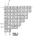
図1は、加圧水型原子炉(PWR)の炉心1のうち1/4の部分を示している。従って、この原子炉は、加圧水によって冷却され、減速される。従来より、炉心1は縦横対称になっているので、対称軸を破線にて示している。
炉心1は、燃料集合体3を備え、燃料集合体は互いに横に並べられ、側部には隙間が設けられている。その結果燃料集合体3の間は、ギャップが設けられ、冷却・減速水によって満たされている。従って、燃料集合体3は、水の層5によって横に区切られ、水の層は燃料集合体3の全高にわたる。
代表的には、これらの水の層5の公称厚みは2mmである。
FIG. 1 shows a quarter of the core 1 of a pressurized water reactor (PWR). Therefore, this nuclear reactor is cooled by the pressurized water and decelerated. Conventionally, since the core 1 is vertically and horizontally symmetric, the axis of symmetry is indicated by a broken line.
The core 1 includes a
Typically, the nominal thickness of these
燃料集合体3、UO2の燃料集合体であって、核燃料として、同位元素235のウランが濃縮されている。従って、燃料集合体3は、炉心1の内部で使用される前には、まったくプルトニウムを含んでいない。
燃料集合体3の一般的な構造は在来のものであるから、詳しくは説明しない。各燃料集合体3は、燃料棒と、これらの燃料棒を、実質的に規則的な格子のノードで支持し保持するスケルトンから構成されていることに留意されたい。
図2の例において、規則的な格子は、正方形ベースと正方形の外部輪郭とを有している。
スケルトンは、下端と、上端と、案内管6とを備え、案内管は2つの端部を結合すると共に、炉心の運転状態を制御すべく制御棒クラスタの制御棒を受け入れる。
スケルトンはさらに、規則的な格子のノードに、燃料棒を保持するための格子7を備える。これらの格子7は従来より、連結板の組を備えていて、これらが共にセル9を区画して、セルは規則的な格子のノードに中心を合わせられる。それぞれのセル9は、燃料棒か、案内管6かを受け入れるもので、中央のセル9はそれ自体、計装管11を受け入れる。
The
The general structure of the
In the example of FIG. 2, the regular grid has a square base and a square outer contour.
The skeleton includes a lower end, an upper end, and a
The skeleton further comprises a grid 7 for holding fuel rods at regular grid nodes . These grids 7 conventionally comprise a set of connecting plates, which together define a
図2の例においては、保持格子7は、各辺について17個のセル9を備えている。従って、格子の外側輪郭は、17個の側部セルからなる正方形になっている。変形例としては、セル9の数を変更して、例えば14×14や15×15としても良い。
燃料棒は3つの群に分配され、すなわち、
・第1の中心群であって、図2では空白になっているセル9を占拠するもの。
・第2の群としての側部燃料棒であって、図2では十字をマークしているセル9を占拠するもの。
・第3の群としての角部燃料棒であって、図2ではハッチングしているセル9を占拠するもの。
図示の例においては、第1の群は200本の燃料棒を備える。この第1の群は、周縁の燃料棒の層13を除けば、格子の全体を占拠する。
従って、この第1の群は、側部セルが15個である正方形に対応し、案内管6と計装管11とによって占拠される25個のセル9を含む。
この第1の群の燃料棒は、核燃料として、第1レベルの濃縮度e1にまで同位元素235で濃縮されたウランを含む。第1レベルの濃縮度e1は、およそ4.11%である。この濃縮度は、同位元素U235の質量比と、核燃料中に存在するウランの合計量とによって定められる。
第2の群の燃料棒は、60本の燃料棒からなり、これらは、周縁層13の4つの面15に分配されている。
In the example of FIG. 2, the holding grid 7 includes 17
The fuel rods are divided into three groups:
A first central group that occupies the
A side fuel rod as the second group, which occupies the
A corner fuel rod as a third group that occupies the hatched
In the example shown, the first group comprises 200 fuel rods. This first group occupies the entire grid , except for the peripheral
This first group thus corresponds to a square with 15 side cells and includes 25
This first group of fuel rods contains uranium enriched with isotope 235 as nuclear fuel to a first level enrichment e1. The first level of enrichment e1 is approximately 4.11%. This enrichment is determined by the mass ratio of the isotope U235 and the total amount of uranium present in the nuclear fuel.
The second group of fuel rods consists of 60 fuel rods, which are distributed on the four
より詳しくは、燃料棒の格子におけるそれぞれの外面15については、15本の燃料棒は、外面15において第2の群に属する2本の角部燃料棒の間に配置されることになる。
第2の群の燃料棒は、核燃料として、同位元素235を第2レベルe2にまで濃縮されたウランを含む。ウラン235についての、かかる第2レベルの濃縮度e2は、およそ3.7%である。
第3の群は、4本のロッドから構成され、格子をなす燃料棒の外側角部を占拠するもので、すなわち、周縁層13の角部を構成する。第3群の核燃料の燃料棒については、その第3レベルの濃縮度e3はおよそ2.8%である。
従って、周縁層13における各面15は、少なくともそれらの両端に、第3群の燃料棒を備え、残余については、第2群の燃料棒を備える。格子における残余の部分は、第1群の燃料棒によって占拠される。燃料集合体3の周縁にわたって連続的に延在する周縁層13の燃料棒は、燃料集合体の中心部における燃料棒の濃縮度に比べて低い濃縮度になっている。
More specifically, for each
The second group of fuel rods includes uranium enriched with the isotope 235 to the second level e2 as nuclear fuel. Such second level enrichment e2 for uranium 235 is approximately 3.7%.
The third group is composed of four rods and occupies the outer corners of the fuel rods forming a lattice , that is, the corners of the
Therefore, each
第1、第2、第3群に属する燃料棒は、同じ形状をもっているけれども、同位元素235の濃縮の度合いが異なっていて、このため、異なった質量の同位元素235を含んでいる。
その結果、燃料集合体3は、使用前にあっては、“領域式”の構造になっていて、角部の燃料棒は低レベルの反応度をもち、角部の間の外面15に沿って配置されて燃料棒は中間的なレベルの反応度をもち、格子に配置されるその他の燃料棒は高いレベルの反応度をもつ。
このタイプの領域式の配置によれば、たとえ燃料集合体3の実際の幾何学形状がその公称の幾何学形状に対して異なっていたとしても、燃料集合体3において満足すべき個々の中性子挙動が確保される。
Although the fuel rods belonging to the first, second, and third groups have the same shape, the degree of enrichment of the isotope 235 is different, and thus includes isotopes 235 of different masses.
As a result, the
According to this type of regional arrangement, the individual neutron behavior to be satisfied in the
図3Aは、従来技術による、つまりすべての燃料棒を均一に濃縮した場合における、同位元素235が濃縮されたウランの燃料集合体について、線出力の分布を示している。関心のある燃料集合体を取り囲む水の層5の厚みは、均一で2mm、すなわち公称値であると仮定している。Y軸上の出力値は、燃料集合体の平均線出力に基づいて、標準化されていることに留意されたい。この出力分布は、150MWj/tの減少率であるとして計算したもので、“キセノン平衡期間の開始”と称される、燃料集合体の運転サイクルの期間に対応している。これは、出力分布が最も不均一であると思われる時刻である。
FIG. 3A shows the line power distribution for a uranium fuel assembly enriched with isotope 235 according to the prior art, ie, when all fuel rods are uniformly enriched. The thickness of the
図3の事例においては、出力分布は均一で、燃料集合体の最大線出力と燃料集合体の平均線出力との比率に対応する、形状係数はおよそ1.053である。形状係数値がおよそ1であることは、出力分布が均一で満足できることを確認している。
図3Bは、図2に示した燃料集合体3についてのチャートである。図示の通り、第3群、つまり燃料集合体の角部にある燃料棒の線出力は、第3群の燃料棒の反応度が低いことから、中央にある第1群の線出力に比べてはるかに低くなっている。同様に、燃料集合体3の外面15に沿って配置された第2群の燃料棒について、これによって提供される線出力は、第1群つまり燃料集合体3の中央にある燃料棒と、角部にある第3群の燃料棒との間の線出力になっている。
In the case of FIG. 3, the power distribution is uniform, and the shape factor corresponding to the ratio of the maximum line output of the fuel assembly to the average line output of the fuel assembly is approximately 1.053. A shape factor value of approximately 1 confirms that the output distribution is uniform and satisfactory.
FIG. 3B is a chart for the
従って、形状係数はおよそ1.068である。従って、従来技術に比べて、若干大きくなっている。しかしながら、出力係数の値は許容できるものであり、図2に示した燃料集合体3は原子炉において用いるのに完全に適している。
図4A及び図4Bは、図3A及び図3Bに対応するもので、水の層5が7mmの均一な厚みになっている。
図示の如く、従来技術(図4A)においては、形状係数は著しく大きくなって、その値は1.186に達している。従って、出力分布は極めて不均一であって、これは原子炉の炉心において防がなければならない。
この事実を後天的に説明すれば、層5の領域にある水の厚みが大きいので、中性子をより大きな程度遅らせて、側部にある燃料棒及び角部にある燃料棒は、より強く熱中性子に暴露され、核分裂が大きくなることができて、もって出力を発生させる。
Therefore, the shape factor is approximately 1.068. Therefore, it is slightly larger than the prior art. However, the power factor value is acceptable and the
4A and 4B correspond to FIGS. 3A and 3B, and the
As shown in the figure, in the conventional technique (FIG. 4A), the shape factor is remarkably large, and the value reaches 1.186. Therefore, the power distribution is very non-uniform and must be prevented in the reactor core.
To explain this fact in an acquired manner, the thickness of the water in the region of
図4Bに示すように、図2に示した燃料集合体3の領域式の配置によれば、燃料集合体3における角部と外面15において、線出力が減少して、はるかに均一な分布を達成している。従って、形状係数の値は1.078になって、これは完全に満足できる値である。
図5A及び図5Bに示すように、同一の現象は、水の層5の均一な厚みが例えば12mmと大きい場合にも見受けられる。従来技術による燃料集合体の場合には、形状係数はおよそ1.342であったが、図2に示した燃料集合体3の場合には、およそ1.181になっている。
As shown in FIG. 4B, according to the region formula arrangement of the
As shown in FIGS. 5A and 5B, the same phenomenon can be seen when the uniform thickness of the
従って、図2に示した燃料集合体3の構造を採用するならば、たとえ局所的に、水の層5が公称値から逸脱した厚みになっていても、出力分布をより均一に確保でき、水の層5の厚みが公称値に対応するならば、全体的には著しくこの分布を害することがない。
従って、図2に示した燃料集合体3によれば、燃料集合体についての機械的な変形や、その製造公差がもつであろう、中性子に関する結果を減少させる。
ある種の事例においては、燃料集合体3は、特に第1群の燃料棒が、ガドリニウムなどの中性子毒を含んでいる。それらの燃料棒においては、同位元素235の濃縮が、同じ群に属する他の燃料棒以下になっている。
Therefore, if the structure of the
Thus, the
In certain cases, the
図6に示した変形例においては、第3群は、4本の角部の燃料棒に加えて、周縁層13と接するような、8本の燃料棒から構成されている。この結果、第3群のロッドは12本の燃料棒から構成される。
しかしながら、この変形例はあまり有利ではないことが見い出されたもので、というのは、水の層の厚みが公称厚みに等しい場合、出力分布をかなり害するためである。
好ましい変形例においては、第2レベルの濃縮度e2はe1−0.8%〜e1−0.2%であり、第3レベルの濃縮度e3はe1−1.8%〜e1−0.6%の範囲である。
第1レベルの濃縮度は好ましくは3%〜6%の範囲である。
また、ひとつの変形例として、第2群と第3群を、同一レベルの同位元素235で濃縮された燃料棒から構成しても良い。すなわち、e2とe3とを等しくする。従って、低レベルの反応度レベルの燃料棒が、周縁層13の全周を占拠し、燃料集合体3の周辺に連続して延在する群を形成する。
さらに別の変形例として、様々な群の燃料棒における反応度のレベルを変化させるためには、同位元素235の濃縮度のレベルを変える代わりに、燃料棒の直径を変化させるようにしても、異なる群における燃料棒の同位元素235の質量を異ならせることができる。
In the modification shown in FIG. 6, the third group is composed of eight fuel rods in contact with the
However, it has been found that this variant is not very advantageous, since the power distribution is significantly detrimental if the thickness of the water layer is equal to the nominal thickness.
In a preferred variant, the second level of enrichment e2 is e1-0.8% to e1-0.2%, and the third level of enrichment e3 is e1-1.8% to e1-0.6. % Range.
The first level of enrichment is preferably in the range of 3% to 6%.
As a modification, the second group and the third group may be composed of fuel rods enriched with the same level of isotope 235. That is, e2 and e3 are made equal. Therefore, the low-reactivity level fuel rods occupy the entire circumference of the
As yet another variation, in order to change the level of reactivity in various groups of fuel rods, instead of changing the enrichment level of the isotope 235, the diameter of the fuel rods may be changed. The masses of fuel rod isotopes 235 in different groups can be varied.
従って、第1群の燃料棒は第1の直径を有し、第2群の燃料棒は第1の直径に比べて厳密に小さい第2の直径を有し、第3群の燃料棒は第2の直径以下である第3の直径を有するようにする。従って、第1、第2、第3の群の燃料棒に含まれる同位元素235の質量は、反応度と共に、少なくなっていく。
より一般的には、正方形以外の多角形の外側輪郭を有しているような格子を形成すべく、燃料棒は燃料集合体の内部に配置することができる。
Thus, the first group of fuel rods has a first diameter, the second group of fuel rods has a second diameter that is strictly smaller than the first diameter, and the third group of fuel rods has a first diameter. Having a third diameter that is less than or equal to two. Therefore, the mass of the isotope 235 contained in the first, second, and third groups of fuel rods decreases with the reactivity.
More generally, the fuel rods can be placed inside the fuel assembly to form a grid having a polygonal outer contour other than a square.
Claims (8)
燃料集合体のほぼ中央に位置し、ウラン235の第1レベルの濃縮度e1を有している燃料棒を備えた第1群の燃料棒と、
この第1群の燃料棒よりも外側に位置する外側周縁層(13)の燃料棒と、を有し、
前記外側周縁層(13)の燃料棒は、前記格子の外側輪郭をなす面(15)に沿って延在している第2群の燃料棒であって、前記第1レベルの濃縮度e1よりも低いウラン235の第2レベルの濃縮度e2を有する前記第2群の燃料棒と、前記格子の外側輪郭における角部に配置された第3群の燃料棒であって、前記第2レベルの濃縮度e2よりも低いウラン235の第3レベルの濃縮度e3を有する前記第3群の燃料棒と、を備えていることを特徴とする燃料集合体。A fuel assembly (3) for a pressurized water reactor of a type in which fuel rods are arranged at nodes of a substantially regular lattice and whose outer contour is a polygon, wherein the fuel rods are isotopes A fuel assembly as described above, comprising 235 enriched uranium and containing no plutonium before the assembly is used in a nuclear reactor,
A first group of fuel rods with fuel rods located approximately in the middle of the fuel assembly and having a first level enrichment e1 of uranium 235 ;
A fuel rod of the outer peripheral layer (13) located outside the fuel rod of the first group,
The fuel rods of the outer peripheral layer (13) are a second group of fuel rods extending along a surface (15) forming the outer contour of the lattice, and from the first level enrichment e1. A second group of fuel rods having a second level enrichment e2 of lower uranium 235, and a third group of fuel rods disposed at corners in the outer contour of the lattice, And a third group of fuel rods having a third level enrichment e3 of uranium 235 lower than the enrichment e2 .
Applications Claiming Priority (3)
| Application Number | Priority Date | Filing Date | Title |
|---|---|---|---|
| FR0313950 | 2003-11-27 | ||
| FR0313950A FR2863097B1 (en) | 2003-11-27 | 2003-11-27 | FUEL ASSEMBLY FOR PRESSURIZED WATER NUCLEAR REACTOR CONTAINING URANIUM ENRICHED WITHOUT PLUTONIUM. |
| PCT/FR2004/003025 WO2005055246A2 (en) | 2003-11-27 | 2004-11-25 | Fuel assembly for a pressurised water nuclear reactor containing enriched uranium and dispensed with plutonium |
Publications (3)
| Publication Number | Publication Date |
|---|---|
| JP2007514141A JP2007514141A (en) | 2007-05-31 |
| JP2007514141A5 JP2007514141A5 (en) | 2011-01-27 |
| JP4728250B2 true JP4728250B2 (en) | 2011-07-20 |
Family
ID=34566198
Family Applications (1)
| Application Number | Title | Priority Date | Filing Date |
|---|---|---|---|
| JP2006540537A Expired - Fee Related JP4728250B2 (en) | 2003-11-27 | 2004-11-25 | Fuel assembly for pressurized water reactor containing enriched uranium containing no plutonium, and core provided with the fuel assembly |
Country Status (11)
| Country | Link |
|---|---|
| US (1) | US7844025B2 (en) |
| EP (1) | EP1687828B1 (en) |
| JP (1) | JP4728250B2 (en) |
| KR (1) | KR101112457B1 (en) |
| CN (1) | CN1898752B (en) |
| AT (1) | ATE438181T1 (en) |
| DE (1) | DE602004022322D1 (en) |
| ES (1) | ES2327532T3 (en) |
| FR (1) | FR2863097B1 (en) |
| WO (1) | WO2005055246A2 (en) |
| ZA (1) | ZA200604171B (en) |
Families Citing this family (10)
| Publication number | Priority date | Publication date | Assignee | Title |
|---|---|---|---|---|
| JP5693466B2 (en) * | 2008-12-17 | 2015-04-01 | エクソンモービル ケミカル パテンツ,インコーポレイティド | Stabilized and dynamically vulcanized thermoplastic elastomer compositions useful in fluid barrier applications |
| CA2810133C (en) | 2010-09-03 | 2021-04-13 | Atomic Energy Of Canada Limited | Nuclear fuel bundle containing thorium and nuclear reactor comprising same |
| CA2817767C (en) | 2010-11-15 | 2018-09-04 | Atomic Energy Of Canada Limited | Nuclear fuel containing a neutron absorber |
| KR102083877B1 (en) * | 2010-11-15 | 2020-03-03 | 아토믹 에너지 오브 캐나다 리미티드 | Nuclear fuel containing recycled and depleted uranium, and nuclear fuel bundle and nuclear reactor comprising same |
| RO129197B1 (en) | 2010-11-15 | 2021-10-29 | Atomic Energy Of Canada Limited | Nuclear fuel containing recycled and depleted uranium and nuclear fuel bundle and nuclear reactor comprising such bundle |
| JP2013231603A (en) * | 2012-04-27 | 2013-11-14 | Nuclear Fuel Ind Ltd | Fuel assembly for pressurized-water reactor |
| US10818403B2 (en) * | 2016-03-29 | 2020-10-27 | Nuscale Power, Llc | Inter-module fuel shuffling |
| RU2717353C1 (en) * | 2016-12-29 | 2020-03-23 | Акционерное Общество "Твэл" | Nuclear reactor fuel assembly |
| CN111899906A (en) * | 2020-08-12 | 2020-11-06 | 中国核动力研究设计院 | Method for producing radioactive isotope based on commercial pressurized water reactor irradiation target |
| EP4338173A1 (en) | 2021-05-11 | 2024-03-20 | Clean Core Thorium Energy LLC | Thorium-based fuel design for pressurized heavy water reactors |
Citations (5)
| Publication number | Priority date | Publication date | Assignee | Title |
|---|---|---|---|---|
| JPS61223582A (en) * | 1985-03-29 | 1986-10-04 | 株式会社日立製作所 | Fuel aggregate for nuclear reactor |
| JPH03249593A (en) * | 1990-02-21 | 1991-11-07 | Siemens Ag | Fuel assembly for pressurized water reactor |
| JPH05323072A (en) * | 1992-02-13 | 1993-12-07 | Nuclear Fuel Ind Ltd | Fuel assembly for pressurized water reactor |
| JPH08201555A (en) * | 1995-01-20 | 1996-08-09 | Genshiryoku Eng:Kk | Mox fuel assembly for pwr |
| JP2001500265A (en) * | 1996-09-13 | 2001-01-09 | ブリテイツシユ・ニユクリアー・フユールズ・ピー・エル・シー | Nuclear fuel assembly |
Family Cites Families (26)
| Publication number | Priority date | Publication date | Assignee | Title |
|---|---|---|---|---|
| US3048532A (en) * | 1961-05-24 | 1962-08-07 | Ii Arthur G Thorp | Cruciform control rod joint |
| US3366546A (en) * | 1965-12-02 | 1968-01-30 | Combustion Eng | Nuclear reactor |
| US3576717A (en) * | 1968-01-24 | 1971-04-27 | Westinghouse Electric Corp | Nuclear reactor structure |
| US3930938A (en) * | 1971-10-11 | 1976-01-06 | Asea-Atom | Attachment and locking of finger control rods in a nuclear reactor of bwr type |
| FR2398367A2 (en) * | 1977-07-22 | 1979-02-16 | Commissariat Energie Atomique | PLATE NUCLEAR FUEL ELEMENT AND ITS MANUFACTURING PROCESS |
| US4326922A (en) * | 1978-02-06 | 1982-04-27 | Westinghouse Electric Corp. | Composite nuclear fuel assembly |
| DE3266144D1 (en) * | 1981-05-15 | 1985-10-17 | Hitachi Ltd | Fuel assembly |
| US4495136A (en) * | 1982-05-11 | 1985-01-22 | Westinghouse Electric Corp. | Maximum power capability blanket for nuclear reactors |
| US4501949A (en) * | 1982-09-01 | 1985-02-26 | Westinghouse Electric Corp. | Movable machining chamber with rotatable work piece fixture |
| FR2552921B1 (en) * | 1983-09-30 | 1985-12-27 | Framatome Sa | FUEL ASSEMBLY FOR A PRESSURE WATER NUCLEAR REACTOR |
| US5207979A (en) * | 1987-11-07 | 1993-05-04 | Hitachi, Ltd. | Nuclear fuel assemblies and reactor cores including them |
| USH722H (en) * | 1988-09-30 | 1990-01-02 | Advanced Nuclear Fuels Corporation | Nuclear reactor fuel with radially varying enrichment |
| DE3850499D1 (en) * | 1988-10-21 | 1994-08-04 | Siemens Ag | Fuel element, in particular for a pressurized water nuclear reactor. |
| JP3105933B2 (en) * | 1991-03-30 | 2000-11-06 | 株式会社東芝 | Fuel assembly |
| FR2693023B1 (en) * | 1992-06-26 | 1994-09-02 | Framatome Sa | Fuel assembly containing plutonium and reactor core using such an assembly. |
| JP2804205B2 (en) * | 1992-09-18 | 1998-09-24 | 株式会社日立製作所 | Fuel assemblies and cores |
| SE470485B (en) * | 1992-09-30 | 1994-05-24 | Asea Atom Ab | Reactor core for a boiler water type nuclear reactor |
| US5416813A (en) * | 1992-10-30 | 1995-05-16 | Kabushiki Kaisha Toshiba | Moderator rod containing burnable poison and fuel assembly utilizing same |
| US5400373A (en) * | 1994-05-16 | 1995-03-21 | Westinghouse Electric Corporation | Assembly fixture and method for fabricating grids |
| JPH0886894A (en) * | 1994-09-14 | 1996-04-02 | Nuclear Fuel Ind Ltd | Mox fuel assembly |
| FR2728718A1 (en) * | 1994-12-23 | 1996-06-28 | Framatome Sa | FUEL ASSEMBLY WITH CONSUMABLE POISON AND REACTOR OPERATING METHOD USING SUCH AN ASSEMBLY |
| JPH102980A (en) * | 1996-06-13 | 1998-01-06 | Hitachi Ltd | Manufacture of fuel assembly and fuel assembly |
| GB9620569D0 (en) * | 1996-10-02 | 1996-11-20 | British Nuclear Fuels Plc | Improvements in and relating to fuels |
| KR100299929B1 (en) * | 1999-03-10 | 2001-09-26 | 임창생 | PHWR Fuel Bundle Assembling and Welding Machine |
| GB0000241D0 (en) * | 2000-01-07 | 2000-03-01 | British Nuclear Fuels Plc | Improvements in and relating to nuclear fuel assemblies |
| JP2002122692A (en) | 2000-10-16 | 2002-04-26 | Global Nuclear Fuel-Japan Co Ltd | Welding equipment for nuclear fuel rod |
-
2003
- 2003-11-27 FR FR0313950A patent/FR2863097B1/en not_active Expired - Fee Related
-
2004
- 2004-11-25 WO PCT/FR2004/003025 patent/WO2005055246A2/en active Application Filing
- 2004-11-25 EP EP04805554A patent/EP1687828B1/en not_active Not-in-force
- 2004-11-25 CN CN2004800387019A patent/CN1898752B/en not_active Expired - Fee Related
- 2004-11-25 US US10/580,678 patent/US7844025B2/en not_active Expired - Fee Related
- 2004-11-25 ES ES04805554T patent/ES2327532T3/en active Active
- 2004-11-25 KR KR1020067010194A patent/KR101112457B1/en active IP Right Grant
- 2004-11-25 AT AT04805554T patent/ATE438181T1/en not_active IP Right Cessation
- 2004-11-25 DE DE602004022322T patent/DE602004022322D1/en active Active
- 2004-11-25 JP JP2006540537A patent/JP4728250B2/en not_active Expired - Fee Related
-
2006
- 2006-05-24 ZA ZA200604171A patent/ZA200604171B/en unknown
Patent Citations (5)
| Publication number | Priority date | Publication date | Assignee | Title |
|---|---|---|---|---|
| JPS61223582A (en) * | 1985-03-29 | 1986-10-04 | 株式会社日立製作所 | Fuel aggregate for nuclear reactor |
| JPH03249593A (en) * | 1990-02-21 | 1991-11-07 | Siemens Ag | Fuel assembly for pressurized water reactor |
| JPH05323072A (en) * | 1992-02-13 | 1993-12-07 | Nuclear Fuel Ind Ltd | Fuel assembly for pressurized water reactor |
| JPH08201555A (en) * | 1995-01-20 | 1996-08-09 | Genshiryoku Eng:Kk | Mox fuel assembly for pwr |
| JP2001500265A (en) * | 1996-09-13 | 2001-01-09 | ブリテイツシユ・ニユクリアー・フユールズ・ピー・エル・シー | Nuclear fuel assembly |
Also Published As
| Publication number | Publication date |
|---|---|
| CN1898752B (en) | 2010-10-20 |
| ATE438181T1 (en) | 2009-08-15 |
| EP1687828A2 (en) | 2006-08-09 |
| JP2007514141A (en) | 2007-05-31 |
| DE602004022322D1 (en) | 2009-09-10 |
| FR2863097B1 (en) | 2008-05-02 |
| KR101112457B1 (en) | 2012-02-22 |
| US7844025B2 (en) | 2010-11-30 |
| EP1687828B1 (en) | 2009-07-29 |
| KR20060129201A (en) | 2006-12-15 |
| ES2327532T3 (en) | 2009-10-30 |
| WO2005055246A2 (en) | 2005-06-16 |
| ZA200604171B (en) | 2007-12-27 |
| FR2863097A1 (en) | 2005-06-03 |
| US20070195919A1 (en) | 2007-08-23 |
| CN1898752A (en) | 2007-01-17 |
| WO2005055246A3 (en) | 2005-10-20 |
Similar Documents
| Publication | Publication Date | Title |
|---|---|---|
| EP1085525B1 (en) | Light water reactor core and fuel assembly | |
| ZA200604171B (en) | Fuel assembly for a pressurised water nuclear reactor plutonium-fre enriched uranium | |
| JP2007514141A5 (en) | ||
| JP2772061B2 (en) | Fuel assembly | |
| JP3874466B2 (en) | Fuel assembly | |
| JP2510565B2 (en) | Reactor fuel assembly | |
| JP3177062B2 (en) | Fuel assembly for light water reactor and light water reactor core | |
| JP2958856B2 (en) | Fuel assembly for boiling water reactor | |
| JP3339768B2 (en) | Light water reactor core | |
| JP4351798B2 (en) | Fuel assemblies and reactors | |
| JP4046870B2 (en) | MOX fuel assembly | |
| JP2610254B2 (en) | Boiling water reactor | |
| JPH01178893A (en) | Fuel assembly for boiling water nuclear reactor | |
| JPH0868886A (en) | Mox fuel assembly for pwr | |
| JPH065320B2 (en) | Fuel assembly for boiling water reactor | |
| JPH0450795A (en) | Fuel assembly | |
| JP2507408B2 (en) | Fuel assembly | |
| JP3894784B2 (en) | Fuel loading method for boiling water reactor | |
| JP2005098924A (en) | Mox fuel assembly | |
| JP2632726B2 (en) | Fuel assembly for boiling water reactor | |
| JP2002196090A (en) | Fuel assembly | |
| JPS61147184A (en) | Fuel aggregate | |
| JP2000075077A (en) | Fuel assembly | |
| JPS62182694A (en) | Fuel aggregate for boiling water type reactor | |
| JPH065316B2 (en) | Fuel assembly |
Legal Events
| Date | Code | Title | Description |
|---|---|---|---|
| A621 | Written request for application examination |
Free format text: JAPANESE INTERMEDIATE CODE: A621 Effective date: 20070822 |
|
| A131 | Notification of reasons for refusal |
Free format text: JAPANESE INTERMEDIATE CODE: A131 Effective date: 20100906 |
|
| A524 | Written submission of copy of amendment under article 19 pct |
Free format text: JAPANESE INTERMEDIATE CODE: A524 Effective date: 20101203 |
|
| TRDD | Decision of grant or rejection written | ||
| A01 | Written decision to grant a patent or to grant a registration (utility model) |
Free format text: JAPANESE INTERMEDIATE CODE: A01 Effective date: 20110404 |
|
| A01 | Written decision to grant a patent or to grant a registration (utility model) |
Free format text: JAPANESE INTERMEDIATE CODE: A01 |
|
| A61 | First payment of annual fees (during grant procedure) |
Free format text: JAPANESE INTERMEDIATE CODE: A61 Effective date: 20110414 |
|
| R150 | Certificate of patent or registration of utility model |
Ref document number: 4728250 Country of ref document: JP Free format text: JAPANESE INTERMEDIATE CODE: R150 Free format text: JAPANESE INTERMEDIATE CODE: R150 |
|
| FPAY | Renewal fee payment (event date is renewal date of database) |
Free format text: PAYMENT UNTIL: 20140422 Year of fee payment: 3 |
|
| R250 | Receipt of annual fees |
Free format text: JAPANESE INTERMEDIATE CODE: R250 |
|
| R250 | Receipt of annual fees |
Free format text: JAPANESE INTERMEDIATE CODE: R250 |
|
| R250 | Receipt of annual fees |
Free format text: JAPANESE INTERMEDIATE CODE: R250 |
|
| R250 | Receipt of annual fees |
Free format text: JAPANESE INTERMEDIATE CODE: R250 |
|
| R250 | Receipt of annual fees |
Free format text: JAPANESE INTERMEDIATE CODE: R250 |
|
| R250 | Receipt of annual fees |
Free format text: JAPANESE INTERMEDIATE CODE: R250 |
|
| R250 | Receipt of annual fees |
Free format text: JAPANESE INTERMEDIATE CODE: R250 |
|
| LAPS | Cancellation because of no payment of annual fees |