JP4724552B2 - Wastewater treatment equipment - Google Patents
Wastewater treatment equipment Download PDFInfo
- Publication number
- JP4724552B2 JP4724552B2 JP2005365120A JP2005365120A JP4724552B2 JP 4724552 B2 JP4724552 B2 JP 4724552B2 JP 2005365120 A JP2005365120 A JP 2005365120A JP 2005365120 A JP2005365120 A JP 2005365120A JP 4724552 B2 JP4724552 B2 JP 4724552B2
- Authority
- JP
- Japan
- Prior art keywords
- ozone gas
- waste water
- wastewater
- treatment tank
- fine bubble
- Prior art date
- Legal status (The legal status is an assumption and is not a legal conclusion. Google has not performed a legal analysis and makes no representation as to the accuracy of the status listed.)
- Expired - Lifetime
Links
Images


Landscapes
- Treatment Of Water By Oxidation Or Reduction (AREA)
Description
本発明は、排水処理装置に関する。より詳しくは、本発明は、難分解性の有機物を含む排水を処理することができる排水処理装置に関する。 The present invention relates to a wastewater treatment apparatus. More particularly, the present invention relates to a wastewater treatment apparatus that can be processed wastewater containing hardly decomposable organic matter.
従来、工場、一般家庭等から排出される有機物等を含有した排水は、曝気処理、活性汚
泥との接触、薬剤の添加、オゾンとの接触、紫外線照射等で有機物等を分解させることに
より処理されている。
Conventionally, wastewater containing organic matter discharged from factories, general households, etc. has been treated by decomposing organic matter etc. by aeration treatment, contact with activated sludge, addition of chemicals, contact with ozone, ultraviolet irradiation, etc. ing.
例えば、オゾンとの接触により排水を処理する手法としては、散気管方式、エジェクタ
ー方式等によりオゾンガスを排水中に溶解させ、有機物等の分解対象物質を酸化分解させ
る処理方法等が知られている(例えば、特許文献1等)。
For example, as a method for treating wastewater by contact with ozone, a treatment method is known in which ozone gas is dissolved in wastewater by an air diffuser method, an ejector method, etc., and a decomposition target substance such as organic matter is oxidized and decomposed ( For example, Patent Document 1).
しかしながら、かかる処理方法では、ほとんどの場合、オゾンガスは、直径1〜3mm
程度の気泡として反応槽内の液中を上昇し、液面から、気体状態のまま外環境に排出され
る場合がある。そのため、かかる処理方法では、液中に溶解せず、液面から気体状態で排
出されるオゾンガス量を考慮して、過剰量のオゾンガスを発生させると共に、過剰量のオ
ゾンガスを供給するため、装置にかかるコストや運転コストがかさみ、排出されたオゾン
ガスを処理するために、活性炭等を用いる排オゾン処理の設置が必要となるという欠点が
ある。
The bubbles in the reaction tank may rise as bubbles of a degree, and may be discharged from the liquid level to the outside environment in a gaseous state. Therefore, in such a processing method, in consideration of the amount of ozone gas that is not dissolved in the liquid and discharged in a gaseous state from the liquid surface, an excessive amount of ozone gas is generated and an excessive amount of ozone gas is supplied to the apparatus. Such costs and operating costs are high, and there is a drawback that it is necessary to install exhaust ozone treatment using activated carbon or the like in order to treat the exhausted ozone gas.
本発明は、上記従来の欠点に鑑みてなされたものであり、オゾンガスが外環境に排出されることを実質的に抑制することができる、排水処理装置を提供することを1つの課題とする。本発明の他の課題は、本明細書の記載から明らかである。 The present invention has been made in view of the above conventional drawbacks, it is possible to substantially prevent the ozone gas is discharged to the outside environment, and one object is to provide a wastewater treatment device . Other problems of the present invention are apparent from the description of the present specification.
本発明は、前記課題に鑑みてなされたものであり、
排水をオゾンガスと接触させて処理する排水の処理方法であって、排水を供給して、下向流を形成させることにより、該排水の液面よりも下方から供給されるオゾンガスの微細気泡の到達上限面を、排水の液面よりも下方に位置せしめる排水の処理方法に用いるための排水処理装置であって、
該排水を供給する排水供給口を有してなる、排水をオゾンガスと接触させて処理する処理槽と、
オゾンガスの微細気泡を、該処理槽内に供給する微細気泡供給部を有してなる微細気泡生成供給装置と、
を備えてなり、
該処理槽内において、該排水供給口よりも下方に該微細気泡供給部が配され、該排水供給口からの排水の供給により、該微細気泡供給部から供給されたオゾンガスの微細気泡の到達上限面を、処理槽本体内の液面よりも下方に位置せしめるように構成されてなり、
該処理槽本体の内部に、循環流を生じさせるための手段がさらに設けられてなり、
該循環流を生じさせるための手段が、該処理槽内に内接し、かつ該処理槽の断面積よりも小さい断面積の開口を有する手段及び/又は双曲面形攪拌翼であることを特徴とする排水処理装置に関する。
また、排水をオゾンガスと接触させて処理する排水の処理方法であって、排水を供給して、下向流を形成させることにより、該排水の液面よりも下方から供給されるオゾンガスの微細気泡の到達上限面を、排水の液面よりも下方に位置せしめる排水の処理方法に用いるための排水処理装置であって、
該排水を供給する排水供給口を有してなる、排水をオゾンガスと接触させて処理する処理槽と、
オゾンガスの微細気泡を、該処理槽内に供給する微細気泡供給部を有してなる微細気泡生成供給装置と、
を備えてなり、
該処理槽内において、該排水供給口よりも下方に該微細気泡供給部が配され、該排水供給口からの排水の供給により、該微細気泡供給部から供給されたオゾンガスの微細気泡の到達上限面を、処理槽本体内の液面よりも下方に位置せしめるように構成されてなり、
該処理槽本体の底部に処理水排出口が設けられ、該処理水排出口より上方に循環水取水口が設けられ、該微細気泡供給発生装置に該循環水取水口からの循環水を流入させる循環水路が設けられてなることを特徴とする排水処理装置に関する。
The present invention has been made in view of the above problems,
A wastewater treatment method for treating wastewater in contact with ozone gas, and by supplying the wastewater to form a downward flow, the arrival of fine bubbles of ozone gas supplied from below the liquid surface of the wastewater A wastewater treatment apparatus for use in a wastewater treatment method in which an upper limit surface is positioned below a liquid level of wastewater,
A treatment tank having a waste water supply port for supplying the waste water, and treating waste water with ozone gas;
A fine bubble generation and supply device having a fine bubble supply unit for supplying fine bubbles of ozone gas into the treatment tank;
With
In the treatment tank, the fine bubble supply unit is disposed below the waste water supply port, and the upper limit of the fine bubbles of ozone gas supplied from the fine bubble supply unit by supplying the waste water from the waste water supply port The surface is configured to be positioned below the liquid level in the treatment tank body,
Means for generating a circulating flow is further provided inside the treatment tank body,
The means for generating the circulating flow is a means inscribed in the treatment tank and having an opening having a cross-sectional area smaller than the cross-sectional area of the treatment tank and / or a hyperboloid stirring blade, The present invention relates to a wastewater treatment apparatus.
Also, a wastewater treatment method for treating wastewater by contacting it with ozone gas, and by supplying the wastewater to form a downward flow, fine bubbles of ozone gas supplied from below the liquid level of the wastewater Is a wastewater treatment device for use in a wastewater treatment method in which the upper limit surface of the wastewater is positioned below the liquid level of wastewater,
A treatment tank having a waste water supply port for supplying the waste water, and treating waste water with ozone gas;
A fine bubble generation and supply device having a fine bubble supply unit for supplying fine bubbles of ozone gas into the treatment tank;
With
In the treatment tank, the fine bubble supply unit is disposed below the waste water supply port, and the upper limit of the fine bubbles of ozone gas supplied from the fine bubble supply unit by supplying the waste water from the waste water supply port The surface is configured to be positioned below the liquid level in the treatment tank body,
A treated water discharge port is provided at the bottom of the treatment tank body, a circulating water intake port is provided above the treated water discharge port, and the circulating water from the circulating water intake port is caused to flow into the fine bubble supply generator. The present invention relates to a wastewater treatment apparatus characterized in that a circulation channel is provided .
<削除> <Delete>
本発明の排水処理装置によれば、処理槽本体内において、排水供給口よりも下方に微細
気泡供給部が配され、排水供給口からの排水の供給により、微細気泡供給部から供給され
たオゾンガスの微細気泡の到達上限面を、処理槽本体内の液面よりも下方に位置せしめる
構成により、オゾンガスが、そのまま外環境に排出されることが実質的に抑制され、導入
されたオゾンガスを実質的に損失することなく排水の処理に利用することができるという
優れた効果を奏する。また、かかる構成により、本発明の排水処理装置によれば、オゾン
ガスの生成に要するエネルギー量等を、より一層削減して運転することができるという優
れた効果を奏する。さらに、かかる構成により、前記液面から気体として排出されるオゾ
ンガスを処理するための処理装置が実質的に要求されないため、設置場所、面積等に応じ
て、コンパクトな大きさに設計されうるという優れた効果を奏する。
According to the waste water treatment apparatus of the present invention, in the treatment tank main body, the fine bubble supply unit is arranged below the waste water supply port, and the ozone gas supplied from the fine bubble supply unit by supplying the waste water from the drain supply port. In this configuration, the upper limit surface of the fine bubbles is positioned below the liquid level in the treatment tank body, so that the ozone gas is substantially prevented from being discharged to the outside environment, and the introduced ozone gas is substantially reduced. There is an excellent effect that it can be used for wastewater treatment without loss. Moreover, according to this structure, according to the waste water treatment apparatus of this invention, there exists an outstanding effect that the amount of energy required for the production | generation of ozone gas etc. can be reduced further, and it can drive | operate. Furthermore, with such a configuration, a processing apparatus for processing ozone gas discharged as a gas from the liquid surface is not substantially required, so that it can be designed in a compact size according to the installation location, area, etc. Has an effect.
さらに、本発明の排水処理装置によれば、処理槽本体内において、排水供給口よりも下
方に微細気泡供給部が配され、排水供給口からの排水の供給により、微細気泡供給部から
供給されたオゾンガスの微細気泡の到達上限面を、処理槽本体内の液面よりも下方に位置
せしめる構成により、導入されたオゾンガスを処理槽本体内の排水の液相中の所望の領域
に高密度で存在させることができるので、導入されたオゾンガスを効率よく分解対象物質
と接触させることができ、高い処理能力を発揮させることができるという優れた効果を奏
する。
Furthermore, according to the wastewater treatment apparatus of the present invention, the fine bubble supply unit is disposed below the wastewater supply port in the treatment tank body, and is supplied from the fine bubble supply unit by the supply of wastewater from the drainage supply port. The upper limit surface of the fine bubbles of ozone gas is positioned below the liquid level in the treatment tank main body, so that the introduced ozone gas can be concentrated in a desired region in the liquid phase of the waste water in the treatment tank main body. Since it can be made to exist, the introduced ozone gas can be efficiently brought into contact with the substance to be decomposed, and an excellent effect that high processing ability can be exhibited is achieved.
また、本発明の排水処理装置が、処理槽本体の内部に、循環流を生じさせるための手段がさらに設けられたものであり、該循環流を生じさせない場合に比べ、同体積あたりの滞留時間を増加させることができるという優れた効果を奏する。また、そのため、本発明の排水処理装置によれば、滞留時間を維持するに適したオゾンガスの存在領域をよりコンパクトに形成させることができるという優れた効果を奏する。 Also, waste water treatment apparatus of the present invention, the inside of the processing tank body state, and are not means is further provided for generating a circulating flow, compared to the case without causing the circulation flow, residence per same volume There is an excellent effect that the time can be increased. Therefore, according to the waste water treatment apparatus of the present invention, there is an excellent effect that the existence region of ozone gas suitable for maintaining the residence time can be formed more compactly.
本発明は、1つの側面では、排水をオゾンガスと接触させて処理する排水の処理方法に用いる排水処理装置であって、排水を供給して、下向流を形成させることにより、該排水よりも下方から供給されるオゾンガスの微細気泡の到達上限面を、排水の液面よりも下方に位置せしめることを特徴とする、排水の処理方法に用いるための排水処理装置に関する。 In one aspect, the present invention is a wastewater treatment apparatus for use in a wastewater treatment method in which wastewater is treated by contacting ozone gas. By supplying wastewater and forming a downward flow, the wastewater treatment apparatus the arrival upper surface of fine bubbles of ozone gas to be supplied from below, characterized in that allowed to positioned lower than the liquid level of the waste water, relates to a waste water treatment apparatus for use in processing methods waste water.
前記排水の処理方法は、前記下向流を形成させることにより、オゾンガスの微細気泡の到達上限面を、排水の液面よりも下方に位置せしめていることに1つの大きな特徴がある。したがって、前記排水の処理方法によれば、オゾンガスと排水との接触に際して、排水の液面から、オゾンガスが、そのまま外環境に排出されることが実質的に抑制されるという優れた効果を発揮する。また、前記排水の処理方法によれば、オゾンガスの微細気泡と排水とを接触させるため、オゾンガスと排水に含まれる分解対象物質とが接触する表面積をより大きくすることができ、より効率的にオゾンガスの能力を発揮させ、処理を行なうことができるという優れた効果を発揮する。 The wastewater treatment method has one major feature in that the upper limit surface of the fine bubbles of ozone gas is positioned below the liquid surface of the wastewater by forming the downward flow. Therefore, according to the processing method of the drainage, upon contact with ozone gas and drainage, from the liquid surface of the waste water, ozone gas, it is discharged to the outside environment is exhibited an excellent effect that is substantially suppressed . Further, according to the processing method of the drainage, for contacting the waste water with fine bubbles of ozone gas, can be a decomposable substance contained in the waste water and ozone gas is greater surface area in contact more efficiently ozone It demonstrates the excellent effect of being able to demonstrate the ability of and perform processing.
なお、排水の液面からのオゾンガスの排出が実質的に抑制されていることは、例えば、オゾン濃度計により供給オゾンガス濃度と液面から排出される排オゾンガス濃度とを測定し、オゾンガス風量にオゾンガス濃度をかけて算出される供給オゾンガス質量に対する排オゾンガス質量の割合として算出されたオゾンガス吸収率が99%以上であることにより確認されうる。 The fact that the discharge of ozone gas from the liquid level of the waste water is substantially suppressed is, for example, that the ozone concentration meter measures the supply ozone gas concentration and the exhaust ozone gas concentration discharged from the liquid surface, It can be confirmed that the ozone gas absorption rate calculated as the ratio of the exhaust ozone gas mass to the supply ozone gas mass calculated by multiplying the concentration is 99% or more.
前記排水の処理方法は、前記下向流が、オゾンガスの微細気泡の到達上限面の位置の制御に用いられていることに1つの大きな特徴がある。したがって、前記排水の処理方法によれば、前記下向流の速度、すなわち、下向流速を制御することにより、オゾンガスと排水との接触に際して、微細気泡の到達上限面が、排水の液面よりも下方にあり、かつ該排水の液相中に処理に適した滞留時間を維持するに適したオゾンガスの存在領域を形成させることができる。さらに、これにより、前記排水の処理方法によれば、オゾンガスが高密度に存在した領域を形成させることもできる。オゾンガスが高密度に存在した領域を形成させた場合には、オゾンガスの微細気泡と、排水中に含まれる分解対象物質との接触をより効率よく行なうことができ、それにより、処理に要する時間をより短縮することもできる。 The wastewater treatment method has one major feature in that the downward flow is used for controlling the position of the upper limit surface of ozone gas fine bubbles. Therefore, according to the processing method of the drainage, the speed of the downward flow, that is, by controlling the downward flow rate upon contact with ozone gas and drainage, has reached the upper limit surface of fine bubbles, the liquid level of the waste water Also, an ozone gas existing region suitable for maintaining a residence time suitable for treatment in the liquid phase of the waste water can be formed. Further, thereby, according to the processing method of the drainage, it is also possible to form the ozone gas is present at a high density area. When a region where ozone gas is present at high density is formed, the fine bubbles of ozone gas and the substance to be decomposed contained in the waste water can be contacted more efficiently, thereby reducing the time required for processing. It can also be shortened.
前記排水としては、特に限定されないが、例えば、酸化により分解される物質、例えば
、有機物質、環境ホルモン(内分泌攪乱物質)〔ノニルフェノール等〕、色素等を含有し
た工業排水又は家庭排水、し尿、メタン発酵分離液等が挙げられる。かかる排水は、前記
オゾンガスによる処理に先立って、生物処理、膜処理等の処理が施された溶液であっても
よい。
The wastewater is not particularly limited. For example, industrial wastewater or household wastewater containing human beings that are decomposed by oxidation, such as organic substances, environmental hormones (endocrine disrupting substances) [nonylphenol, etc.], pigments, etc., human waste, methane A fermentation separation liquid etc. are mentioned. Such waste water may be a solution that has been subjected to treatment such as biological treatment or membrane treatment prior to treatment with the ozone gas.
前記排水処理方法において、オゾンガスの供給量は、特に限定されないが、例えば、排水の組成、分解対象物質の種類、気泡径、オゾンの溶解速度等に対応する滞留時間に応じて、適宜設定されうる。 In the wastewater treatment method, the supply amount of ozone gas is not particularly limited, but can be appropriately set according to, for example, the residence time corresponding to the composition of the wastewater, the type of substance to be decomposed, the bubble diameter, the dissolution rate of ozone, and the like. .
オゾンガスの微細気泡は、例えば、微細気泡生成供給装置等により発生させうる。前記
微細気泡生成供給装置としては、微細気泡を発生させることができるものであればよく、
特に限定されないが、例えば、旋回流発生部内に液体を加圧ポンプ等で圧送し、旋回流を
発生させて、高遠心力場を発生させるとともに、かかる高遠心力場に気体を導入して、液
体と気体とを混合することにより微細気泡を発生させる機構を有する装置等が挙げられる
。前記微細気泡生成供給装置としては、具体的には、例えば、流通方向に向かって縮径す
る円錐台形状の内面を有する管体からなる、排水の旋回流を発生させる旋回流発生部と、
排水を吸引して加圧状態で旋回流発生部に排水を送り出す加圧ポンプと、
旋回流発生部にオゾンガスを導入するオゾンガス発生装置と
旋回流発生部で生成した微細気泡を、処理槽本体内に供給する微細気泡供給部と、
を備え、
処理槽と加圧ポンプ入口とが配管により接続され、
加圧ポンプ出口と旋回流発生部入口とが、旋回流発生部の円錐台形状の径大側において円
周方向に排水が導入されるように配管により接続され、
微細気泡供給部が、オゾンガスによる処理に際して、処理槽本体内の排水中に浸漬された
状態で配され、
オゾンガス発生装置で発生したオゾンが旋回流発生部に導入され、旋回流によりオゾンガ
スが剪断され、生成した微細気泡が、旋回流発生部の円錐台形状の径小側から微細気泡供
給部に移送され、それにより、微細気泡供給部からオゾンガスの微細気泡が排出されるよ
うに構成されている微細気泡生成供給装置等が挙げられる。
The fine bubbles of ozone gas can be generated by, for example, a fine bubble generation and supply device. The fine bubble generation and supply device may be any device that can generate fine bubbles,
Although not particularly limited, for example, a liquid is pumped into the swirl flow generation unit with a pressurizing pump or the like to generate a swirl flow, and a high centrifugal force field is generated. Examples thereof include an apparatus having a mechanism for generating fine bubbles by mixing with gas. Specifically, as the fine bubble generation and supply device, for example, a swirl flow generating unit that generates a swirl flow of drainage, which includes a tubular body having a truncated cone-shaped inner surface that is reduced in diameter in the flow direction,
A pressure pump that sucks the waste water and sends the waste water to the swirl flow generator in a pressurized state;
An ozone gas generator that introduces ozone gas into the swirl flow generator, and a fine bubble supply unit that supplies the fine bubbles generated in the swirl flow generator into the treatment tank body;
With
The treatment tank and the pressure pump inlet are connected by piping,
The pressure pump outlet and the swirl flow generating unit inlet are connected by piping so that drainage is introduced in the circumferential direction on the large diameter side of the circular truncated cone of the swirl flow generating unit,
During the treatment with ozone gas, the fine bubble supply part is arranged in a state immersed in the waste water in the treatment tank body,
Ozone generated by the ozone gas generator is introduced into the swirl flow generation unit, the ozone gas is sheared by the swirl flow, and the generated fine bubbles are transferred to the fine bubble supply unit from the small diameter side of the frustoconical shape of the swirl flow generation unit. Thus, a fine bubble generation and supply device configured so that fine bubbles of ozone gas are discharged from the fine bubble supply unit can be used.
前記オゾンガスの微細気泡としては、気泡発生時直径80μm以下の微細気泡が挙げら
れる。
Examples of the fine bubbles of ozone gas include fine bubbles having a diameter of 80 μm or less when bubbles are generated.
なお、本明細書において、前記「気泡発生時直径80μm以下の微細気泡」とは、微細
気泡供給部から排出される全気泡の内の80%以上(個数)の気泡が直径80μm以下の
大きさであるものを意図する。
In the present specification, the term “fine bubbles having a diameter of 80 μm or less when bubbles are generated” means that 80% or more (number) of bubbles discharged from the fine bubble supply unit have a diameter of 80 μm or less. Intended to be.
かかる気泡の大きさは、前記微細気泡供給部から排出される気泡を、微細気泡供給部出
口近傍でマイクロスコープ等を用いて撮影し、撮影された写真を画像解析等に供すること
により求められうる。具体的には、気泡の大きさは、例えば、微細気泡供給部出口近傍(
すなわち、出口から50mmの位置)において、微細気泡供給部から排出される気泡を、
20倍程度の倍率のマイクロスコープ等を用いて撮影し、撮影された写真を、例えば、旭
化成エンジニアリング株式会社、商品名:A像くん等の画像解析ソフトにより解析し、そ
れにより、円相当径を算出することにより求められうる。
The size of the bubbles can be obtained by photographing the bubbles discharged from the fine bubble supply unit using a microscope or the like in the vicinity of the outlet of the fine bubble supply unit, and using the photographed image for image analysis or the like. . Specifically, the size of the bubble is, for example, near the outlet of the fine bubble supply unit (
That is, at a position of 50 mm from the outlet), the bubbles discharged from the fine bubble supply unit are
Photographed using a microscope with a magnification of about 20 times, and the photographed photographs were analyzed by image analysis software such as Asahi Kasei Engineering Co., Ltd., trade name: A Image-kun, etc. It can be obtained by calculating.
また、「80%以上の気泡が80μm以下の大きさ」であることは、上記のように画像
解析された全気泡のうち、80%以上の気泡が直径80μm以下の円相当径として観察さ
れることによりで確認されうる。
In addition, “80% or more of bubbles are 80 μm or less” means that 80% or more of the bubbles analyzed as described above are observed as an equivalent circle diameter of 80 μm or less in diameter. Can be confirmed.
排水の供給による下向流速は、気泡発生時における微細気泡の気泡径、排水の密度等に
応じて設定されうる。かかる下向流速は、例えば、下記式1:
The downward flow rate due to the supply of drainage can be set according to the bubble diameter of fine bubbles, the density of drainage, and the like when bubbles are generated. The downward flow velocity is, for example, the following formula 1:
![]()
![]()
〔式中、Ubは、下向流速(mm/s)、dbは、気泡径(μm)である〕
を満たす範囲であればよい。具体的には、例えば、20℃、1気圧下で、発生時直径50
μmの微細気泡で、排水の供給の際の垂直方向での初速度が、少なくとも1.35mm/
秒、好ましくは、1.35mm/秒〜5.5mm/秒、より好ましくは、1.35mm/
秒〜1.4mm/秒である場合、オゾンガスの微細気泡の到達上限面を、排水の液面より
も下方に位置するように良好に制御されうる。
[Where Ub is the downward flow velocity (mm / s) and db is the bubble diameter (μm)]
It may be in a range satisfying the above. Specifically, for example, at the time of occurrence at 20 ° C. and 1 atm, the diameter 50
The initial velocity in the vertical direction when supplying wastewater is at least 1.35 mm / μm with fine bubbles of μm.
Second, preferably 1.35 mm / second to 5.5 mm / second, more preferably 1.35 mm / second
In the case of the second to 1.4 mm / second, the reaching upper limit surface of the fine bubbles of ozone gas can be well controlled so as to be positioned below the liquid level of the waste water.
前記排水の処理方法においては、オゾンガスの微細気泡の気泡径に基づき、排水の液相中の予め定められた点における排水の下向流速を調整することにより、微細気泡の到達上限面を前記液相の液面よりも下方に位置せしめ、かつ該液相中に処理に適した滞留時間を維持するに適したオゾンガスの存在領域を形成させることが好ましい。これにより、前記排水の処理方法によれば、より効率よく排水とオゾンガスとを接触させることができるという優れた効果を発揮する。 In the wastewater treatment method, the lower limit flow velocity of the wastewater at a predetermined point in the liquid phase of the wastewater is adjusted based on the bubble diameter of the fine bubbles of ozone gas, so that the upper limit surface of the fine bubbles is reached. It is preferable that an ozone gas existing region suitable for maintaining a residence time suitable for processing is formed in the liquid phase and positioned below the liquid level of the phase. Thereby, according to the said wastewater processing method, the outstanding effect that wastewater and ozone gas can be contacted more efficiently is exhibited.
前記液相中の予め定められた点は、微細気泡の到達上限面内の定点であればよい。前記排水の処理方法においては、例えば、前記微細気泡の到達上限面内の定点において、垂直方向での下向流速の絶対値を、前記オゾンガスの微細気泡の垂直方向での上昇速度の絶対値と同一に又は大きくなるように維持させうる。これにより、オゾンガスの微細気泡の到達上限面を前記液相の液面よりも下方に位置させることができ、かつ、前記液相中の任意の位置にオゾンガスの存在領域を形成させることができる。 The predetermined point in the liquid phase may be a fixed point within the upper limit plane of the fine bubbles . In the wastewater treatment method, for example, the absolute value of the downward flow velocity in the vertical direction at a fixed point in the upper limit surface of the fine bubbles, and the absolute value of the rising speed of the ozone gas in the vertical direction It can be kept the same or larger. Thereby, the reach | attainment upper limit surface of the fine bubble of ozone gas can be located below the liquid level of the said liquid phase, and the ozone gas presence area | region can be formed in the arbitrary positions in the said liquid phase.
前記下向流速は、例えば、80%以上の気泡が直径80μm以下の円相当径である場合
には、80μmの微細気泡が上昇しない下向流速、例えば、3.4565mm/秒に設定
されうる。
For example, when 80% or more of bubbles have an equivalent circle diameter of 80 μm or less, the downward flow rate can be set to a downward flow rate at which 80 μm fine bubbles do not rise, for example, 3.4565 mm / second.
前記オゾンガスの存在領域の大きさや位置は、特に限定されるものではなく、排水の組
成、分解対象物質の種類等に対応する滞留時間等に応じて、適宜設定されうる。
The size and position of the ozone gas existence region are not particularly limited, and can be appropriately set according to the residence time corresponding to the composition of the waste water, the type of the decomposition target substance, and the like.
さらに、前記排水の処理方法では、より効率よく処理を行なう観点から、好ましくは、排水の液相内に循環流を生じさせることが望ましい。前記排水の処理方法において、前記液相内に循環流を生じさせることは、循環流を生じさせない場合に比べ、同体積あたりの滞留時間を増加させることができる点で有利である。 Further , in the wastewater treatment method, it is preferable to generate a circulating flow in the liquid phase of the wastewater from the viewpoint of more efficient treatment. In the wastewater treatment method, generating a circulating flow in the liquid phase is advantageous in that the residence time per volume can be increased as compared to a case where no circulating flow is generated.
前記循環流は、例えば、双曲面形攪拌翼等により生じさせうる。なお、本明細書におい
て、前記双曲面形攪拌翼とは、上面視円形で、該円形の中心部に向けた仰角が中心部に近
いほど大きな値となるように中央部が隆起し、側面視の稜線が二次関数曲線(y=ax2
)の一部と略同一となるよう形成された板状基体を有し、該板状基体の上面には中心部か
ら放射状に複数のリブが形成され、かつ板状基体がその中心部を軸に水平方向に回転した
ときに前記リブが回転方向に対して後退するよう板状基体の上面に形成され、板状基体が
その中心部を軸に略水平方向に回転するように用いられる攪拌翼をいう。
The circulating flow can be generated by, for example, a hyperboloid stirring blade or the like. In the present specification, the hyperboloid stirring blade is a circular shape in a top view, and the central portion is raised so that the elevation angle toward the central portion of the circular shape is closer to the central portion, and the side surface view Is the quadratic function curve (y = ax2
), A plurality of ribs are formed radially from the central portion on the upper surface of the plate-shaped substrate, and the plate-shaped substrate is pivoted about the central portion. The stirring blade is formed on the upper surface of the plate-like base so that the rib moves backward with respect to the rotation direction when the plate-like base is rotated in the horizontal direction. Say.
また、前記循環流は、例えば、図2に例示されるように、液相の下部から、ポンプ等に
より液を引き抜き、液相の上部に戻すような循環流であってもよい。この場合、循環流の
水量q(m3/秒)は、気泡上昇を抑制する下向流速を発生させるために必要な流量を循
環流量によって確保する観点から、好ましくは、下記式2:
Further, as illustrated in FIG. 2, for example, the circulating flow may be a circulating flow in which a liquid is drawn from the lower part of the liquid phase by a pump or the like and returned to the upper part of the liquid phase. In this case, the water amount q (
![]()
![]()
〔式中、Dは、排水処理に用いられる処理槽の内径(m)であり、Qは、該処理槽に供給
される排水の流量(m3/秒)であり、dは、気泡発生時の微細気泡の外径(μm)であ
る〕を満たすことが望ましい。なお、処理槽が矩形の場合は、循環流の水量q(m3/秒
)は、下記式3:
[In the formula, D is the inner diameter (m) of the treatment tank used for wastewater treatment, Q is the flow rate (m3 / second) of wastewater supplied to the treatment tank, and d is the time when bubbles are generated. It is desirable that the outer diameter (μm) of the fine bubbles is satisfied. When the treatment tank is rectangular, the amount of water q (
![]()
![]()
〔式中、a及びbは、排水処理に用いられる処理槽の辺の長さ(m)であり、Qは、該処
理槽に供給される排水の流量(m3/秒)であり、dは、気泡発生時の微細気泡の外径(
μm)である〕を満たすことが望ましい。
[Wherein, a and b are the length (m) of the side of the treatment tank used for wastewater treatment, Q is the flow rate (m3 / second) of wastewater supplied to the treatment tank, and d is , The outer diameter of the fine bubbles at the time of bubble generation (
[mu] m)].
本発明は、前記排水の処理方法に用いるための排水処理装置であって、
該排水を供給する排水供給口を有してなる、排水をオゾンガスと接触させて処理する処理
槽と、
オゾンガスの微細気泡を、該処理槽本体内に供給する微細気泡供給部を有した微細気泡生
成供給装置と、
を備え、
該処理槽本体内において、該排水供給口よりも下方に該微細気泡供給部が配され、該排水
供給口からの排水の供給により、該微細気泡供給部から供給されたオゾンガスの微細気泡
の到達上限面を、処理槽本体内の液面よりも下方に位置せしめるように構成されているこ
とを特徴とする排水処理装置に関する。
The present invention relates to a waste water treatment apparatus for use in processing method of the drainage,
A treatment tank having a waste water supply port for supplying the waste water, and treating waste water with ozone gas;
A fine bubble generation and supply device having a fine bubble supply unit for supplying fine bubbles of ozone gas into the processing tank body;
With
In the treatment tank main body, the fine bubble supply unit is disposed below the waste water supply port, and the supply of waste water from the waste water supply port reaches the arrival of fine bubbles of ozone gas supplied from the fine bubble supply unit. The present invention relates to a wastewater treatment apparatus configured to position an upper limit surface below a liquid surface in a treatment tank main body.
本発明の排水処理装置は、処理槽本体内において、排水供給口よりも下方に微細気泡供
給部が配され、排水供給口からの排水の供給により、微細気泡供給部から供給されたオゾ
ンガスの微細気泡の到達上限面を、処理槽本体内の液面よりも下方に位置せしめるように
構成されていることに1つの大きな特徴がある。本発明の排水処理装置は、かかる構成を
有していることにより、オゾンガスが、そのまま外環境に排出されることが実質的に抑制
され、導入されたオゾンを実質的に損失させることなく利用することができるという優れ
た効果を発揮する。また、かかる構成により、本発明の排水処理装置によれば、オゾンガ
スの生成に要するエネルギー量等を、より削減して運転することができるという優れた効
果を発揮する。さらに、かかる構成は、液面から排出されるオゾンガスを処理するための
処理装置が実質的に要求されないため、設置場所、面積等に応じて、コンパクトな大きさ
に設計できる点でも有利である。また、本発明の排水処理装置によれば、前記構成を有し
ているため、排水の供給の際の下向流速を制御することにより、処理槽本体内において、
導入されたオゾンガスを所望の領域に高密度で存在させることができる。そのため、本発
明の排水処理装置によれば、導入されたオゾンガスを効率よく分解対象物質と接触させる
ことができ、高い処理能力を発揮させることができるという優れた効果を発揮する。
In the wastewater treatment apparatus of the present invention, the fine bubble supply unit is disposed below the wastewater supply port in the treatment tank body, and the fineness of ozone gas supplied from the fine bubble supply unit by the supply of wastewater from the drainage supply port. One major feature is that the upper limit surface of the bubbles is configured to be positioned below the liquid surface in the treatment tank body. Since the wastewater treatment apparatus of the present invention has such a configuration, ozone gas is substantially prevented from being discharged to the outside environment as it is, and is used without substantially losing the introduced ozone. It exhibits the excellent effect of being able to. Moreover, according to this structure, according to the waste water treatment apparatus of this invention, the outstanding effect that the amount of energy required for the production | generation of ozone gas, etc. can be reduced more is exhibited. Further, such a configuration is advantageous in that a processing device for processing ozone gas discharged from the liquid surface is not substantially required, and therefore it can be designed in a compact size according to the installation location, area, and the like. In addition, according to the wastewater treatment apparatus of the present invention, because it has the above-described configuration, by controlling the downward flow velocity when supplying wastewater,
The introduced ozone gas can be present at a high density in a desired region. Therefore, according to the waste water treatment apparatus of the present invention, the introduced ozone gas can be efficiently brought into contact with the substance to be decomposed, and an excellent effect that a high treatment capacity can be exhibited is exhibited.
また、本発明の排水処理装置は、好ましくは、処理槽本体の底部に処理水排出口が設け
られ、該処理水排出口より上方に循環水取水口が設けられ、該微細気泡供給発生装置に該
循環水取水口からの循環水を流入させる循環水路が設けられうる。
In the wastewater treatment apparatus of the present invention, preferably, a treated water discharge port is provided at the bottom of the treatment tank main body, and a circulating water intake port is provided above the treated water discharge port. A circulating water channel through which the circulating water from the circulating water intake is introduced can be provided.
前記循環水取水口は、好ましくは、微細気泡供給部よりも下方に設けられる。 The circulating water intake is preferably provided below the fine bubble supply unit.
以下、図1〜図5それぞれに示される実施態様1〜5を一例として挙げ、本発明の排水
処理装置を具体的に説明するが、本発明は、かかる実施態様に限定されるものではない。
Hereinafter, the
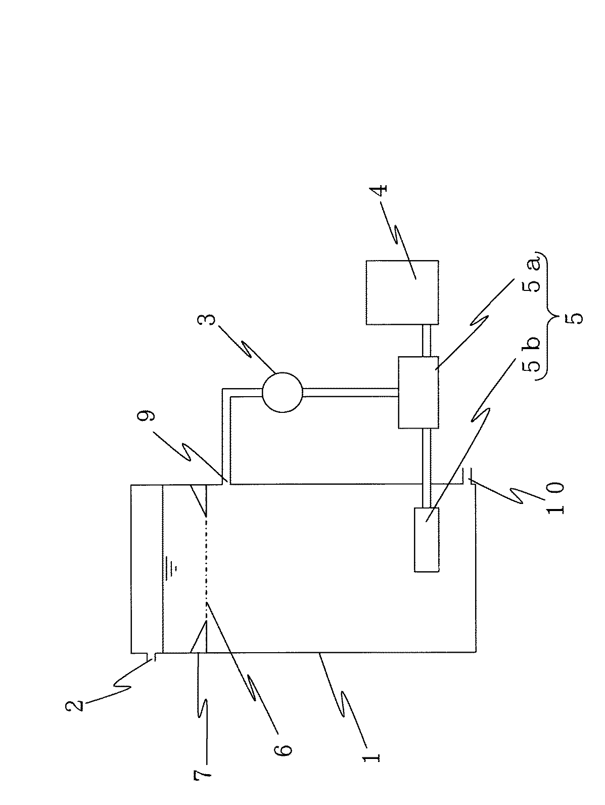
図1に示される実施態様1の排水処理装置は、排水を供給する排水供給口2を有し、排
水をオゾンガスと接触させて処理する処理槽1と、
オゾンガスを発生させるオゾンガス発生部4と、
処理槽1から排水を導入して、旋回流を発生させ、排水と、オゾンガス発生部4から導入
されたオゾンガスとを混合してオゾンガスの微細気泡を発生させる旋回流発生部5aと、
旋回流発生部5aで生成した微細気泡を、該処理槽本体内の排水に供給する微細気泡供給
部5bとを有した微細気泡生成供給装置5と、
処理後に得られた処理水を排出する処理水排出口10と、
を備え、
処理槽1内において、排水供給口2よりも下方に微細気泡供給部5bが配され、排水供給
口2からの排水の供給により、微細気泡供給部5bから供給されたオゾンガスの微細気泡
の到達上限面6を、処理槽1本体内の液面よりも下方に位置せしめるように構成されてい
ることを特徴とする装置である。
The waste water treatment apparatus of
An
A swirl flow generator 5a that introduces waste water from the
A fine bubble generation and
A treated
With
In the
前記実施態様1の排水処理装置において、微細気泡生成供給装置5は、旋回流発生部5
aと、微細気泡供給部5bとを備えた装置である。
In the wastewater treatment apparatus of the first embodiment, the fine bubble generation and
a and a fine bubble supply unit 5b.
前記実施態様1の排水処理装置において、オゾンガス発生部4としては、特に限定され
ないが、例えば、無声放電により酸素を電気分解してオゾンを生成させる装置等が挙げら
れる。
In the wastewater treatment apparatus of the first embodiment, the ozone
処理槽1と微細気泡生成供給装置5とは、処理槽1本体に設けられた排水を循環水とし
て取り込む循環水取水口9と、排水を吸引して加圧状態で、微細気泡装置5の旋回流発生
部5aに排水を送り出す加圧ポンプ3と配管とにより接続されている。ここで、循環水取
水口9と加圧ポンプ3の入口とは、配管により接続され、加圧ポンプ3の出口と旋回流発
生部5aの入口とが、旋回流発生部5aの円錐台形状の径大側において円周方向に排水が
導入されるように配管により接続されている。
The
また、微細気泡装置5の微細気泡供給部5bは、処理槽1内において、オゾンガスによ
る処理に際して、処理槽本体内の排水中に浸漬された状態で配されている。処理槽1にお
いて、微細気泡供給部5bは、循環水取水口9よりも下方に位置するように配されている
。尚、オゾンガスの微細気泡の到達上限面6は、循環水取水口9よりも上方に位置する。
The fine bubble supply unit 5b of the
オゾンガス発生部4と微細気泡生成供給装置5の旋回流発生部5aとは、配管により接
続され、旋回流発生部5aと微細気泡供給部5bとが配管により接続されている。かかる
構成により、オゾンガス発生部4でオゾンガスが生成され、生成されたオゾンガスが旋回
流発生部5aに導入され、かかる旋回流発生部5aにおいて、排水の導入により発生した
旋回流によりオゾンガスが剪断されて、微細気泡が生成され、生成された微細気泡が、旋
回流発生部5aの円錐台形状の径小側から微細気泡供給部5bに移送され、それにより、
微細気泡供給部5bから発生時直径80μm以下のオゾンガスの微細気泡が排出され、処
理槽1内に供給される。
The ozone
Ozone gas microbubbles having a diameter of 80 μm or less are discharged from the microbubble supply unit 5 b and supplied into the
前記実施態様1の排水処理装置において、処理槽1としては、例えば、円筒、四角柱等
の形状の処理槽等が挙げられる。なかでも、オゾンガスと、排水中に含まれる分解対象物
質との接触をより効率よく行なう観点から、好ましくは、円筒形状の処理槽が望ましい。
In the wastewater treatment apparatus of the first embodiment, examples of the
処理槽1の大きさは、前記液面から排出されるオゾンガスの抑制効率を向上させる観点
から、円筒形状の処理槽である場合、好ましくは、処理槽1の内径を、下記式4:
From the viewpoint of improving the suppression efficiency of ozone gas discharged from the liquid surface, the size of the
〔式中、Dは、処理槽の内径(m)であり、Qは、処理槽に供給される排水の流量(m3
/秒)であり、dは、気泡発生時の微細気泡の外径(μm)である〕
を満たすように設定することが望ましい。
[In the formula, D is the inner diameter (m) of the treatment tank, and Q is the flow rate (m3 of waste water supplied to the treatment tank).
D is the outer diameter (μm) of the fine bubbles when the bubbles are generated.]
It is desirable to set so as to satisfy.
処理水排出口10は、好ましくは、処理槽1本体の底部に設けられていることが望まし
い。また、処理水排出口10は、微細気泡供給部5bよりも下方に配されるように構成さ
れうる。
The treated
図2に示される実施態様2の排水処理装置は、前記実施態様1の排水処理装置において
、微細気泡供給部5bが、循環水取水口9よりも上方に位置するように配され、処理水排
出口10が、循環水取水口9よりも下方に位置するように配されていることを特徴とする
装置である。この構成により気泡と排水とが接する時間が長くなり,十分な反応時間が確
保できるという点に優れる。尚、オゾンガスの微細気泡の到達上限面6は、微細気泡供給
部5bよりも上方に位置する。
The wastewater treatment apparatus of
図3に示される実施態様3の排水処理装置は、前記実施態様1の排水処理装置において
、処理槽1の内径(断面積)を部分的に小さくする断面積調節手段7が、処理槽1に内設
されていることを特徴とする装置である。かかる構成により、より簡便に、オゾンガスの
微細気泡の到達上限面6を処理槽1本体内の液面よりも下方に位置せしめるように構成す
ることが可能になる。
The waste water treatment apparatus of
前記断面積調節手段7は、処理槽内に内接し、かつ処理槽の断面積よりも小さい断面積
の開口を有する手段である。尚、断面積調節手段7により断面積が小さくなった開口の面
が、オゾンガスの微細気泡の到達上限面6となる。
The cross-sectional area adjusting means 7 is a means inscribed in the processing tank and having an opening having a cross-sectional area smaller than the cross-sectional area of the processing tank. The surface of the opening whose cross-sectional area is reduced by the cross-sectional area adjusting means 7 is the
かかる断面積調節手段7は、循環水取水口9よりも上方に位置するように配されている
ことを特徴とする装置である。かかる構成により、液面からのオゾンの排出が抑制され、
また、排水の循環によって滞留時間が長くなるという点に優れる。
The cross-sectional area adjusting means 7 is an apparatus characterized in that it is arranged to be located above the circulating
Moreover, it is excellent in the point that residence time becomes long by circulation of waste_water | drain.
図4に示される実施態様4の排水処理装置は、前記実施態様1の排水処理装置において
、処理槽1本体内に、循環流を生じさせる循環流発生手段8がさらに設けられていること
を特徴とする装置である。かかる構成により、循環流を生じさせない場合に比べ、同体積
あたりの滞留時間を増加させることができるという優れた効果を発揮する。また、そのた
め、実施態様4の排水処理装置によれば、滞留時間を維持するに適したオゾンガスの存在
領域をよりコンパクトに形成させることができる。
The waste water treatment apparatus of
循環流発生手段8としては、特に限定されないが、例えば、前記双曲面形攪拌翼等が挙
げられる。前記双曲面形攪拌翼は、運転に際し、エネルギーの消費が少なく、循環流を制
御しやすく、該循環流を効率よく発生させることができる点で有利である。
The circulating flow generating means 8 is not particularly limited, and examples thereof include the hyperboloid stirring blades. The hyperboloid agitating blade is advantageous in that it consumes less energy during operation, can easily control the circulating flow, and can efficiently generate the circulating flow.
図5に示される実施態様5の排水処理装置は、前記実施態様1の排水処理装置において
、処理槽1の内径(断面積)を部分的に小さくする断面積調節手段7が、処理槽1に内設
され、かつ処理槽1本体内に、循環流を生じさせる循環流発生手段8がさらに設けられて
いることを特徴とする装置である。かかる構成により、微細気泡の到達上限面6を、処理
槽本体内の排水の液面よりも下方に配し、かつ該液相中に処理に適した滞留時間を維持す
るに適したオゾンガスの存在領域を、よりコンパクトになるように形成させうる。また、
かかる構成は、より簡便に、オゾンガスの微細気泡を高密度に存在させることができる点
で有利である。かかる実施態様5の排水処理装置においては、循環水取水口9は、断面積
調整手段7の下方に配されている。
The wastewater treatment apparatus of
Such a configuration is advantageous in that the fine bubbles of ozone gas can be easily present at high density. In the wastewater treatment apparatus of this fifth embodiment, the circulating
以下、本発明を実施例等により詳細に説明するが、本発明は、かかる実施例に限定され
るものではない。
EXAMPLES Hereinafter, although an Example etc. demonstrate this invention in detail, this invention is not limited to this Example.
(実施例1)
図1に示される排水処理装置を用い、種々の気泡発生時直径(外径)の微細気泡のオゾ
ンガスを発生させた場合に、液面からのオゾンガスの流出を抑制するために必要な排水の
供給速度〔下向流速(mm/秒)〕を求めた。結果を図6に示す。
Example 1
Supply of waste water necessary to suppress the outflow of ozone gas from the liquid surface when the fine bubble ozone gas having various diameters (outer diameters) is generated using the waste water treatment apparatus shown in FIG. The speed [downward flow rate (mm / sec)] was determined. The results are shown in FIG.
その結果、図6に示されるように、例えば、気泡発生時直径50μmの微細気泡のオゾ
ンガスの場合、少なくとも1.35mm/秒の下向流速により、液面からのオゾンガスの
排出を抑制することができることがわかる。なお、対照として、下向流速1.38mm/
秒として、図1に示される排水処理装置の微細気泡生成供給装置5に代えて、従来の散気
管(焼結フィルタータイプ)を備えた装置を用いて、気泡発生時直径2mmの気泡を処理
槽1内に供給した場合、かかる気泡のオゾンガスは、0.216m/sの速度で上昇し、
液面から排出された。
As a result, as shown in FIG. 6, for example, in the case of a fine bubble ozone gas having a diameter of 50 μm at the time of bubble generation, the downward flow velocity of at least 1.35 mm / second can suppress the discharge of ozone gas from the liquid surface. I understand that I can do it. As a control, the downward flow velocity is 1.38 mm /
As a second, instead of the fine bubble generation and
It was discharged from the liquid level.
(実施例2)
COD Mnが7.2〜12.5mg/Lの排水を、図1に示される排水処理装置に供
し、気泡発生時直径50μmの微細気泡(即ち、全微細気泡数の80%が50μm以下の
微細気泡)のオゾンガスにより排水のオゾン処理を行なった。ここで、処理槽1の寸法は
、内径200mm、高さ2900mm、有効水深2500mm、有効容量78.5L、排
水供給口2の設置位置は、処理槽1上部であり、排水供給口2の大きさは、直径5mmで
あり、処理水排出口10の設置位置は、処理槽1下部である。また、排水の供給水量2.
6L/分(滞留時間30分間)、7.9L/分(滞留時間10分間)又は13.1L/分
(滞留時間6分間)とした。また、図1に示される排水処理装置の上部にオゾン濃度計を
設置した。オゾン処理後の排水について、オゾン吸収率及びCOD減少率を評価した。な
お、COD Mnは、JIS K 0102 (1998) 17 滴定法に準じて測定
した。
(Example 2)
The waste water having COD Mn of 7.2 to 12.5 mg / L is supplied to the waste water treatment apparatus shown in FIG. 1, and fine bubbles with a diameter of 50 μm when bubbles are generated (that is, fine bubbles with 80% of the total number of fine bubbles are 50 μm or less). The wastewater was subjected to ozone treatment with ozone gas in the form of bubbles. Here, the dimensions of the
It was 6 L / min (
オゾン吸収率は、処理槽1に供給されるオゾン量(オゾンガス発生部から微細気泡生成
供給装置へ供給されるオゾン含有ガスの圧力×供給ガス容積×オゾン濃度)と、処理槽1
から排出される排ガス中のオゾン量(処理槽1の排ガス出口から排出される排ガスの圧力
×排ガス容積×オゾン濃度)との差を、処理槽1に供給されるオゾン量の値で割ることに
より算出した。
The ozone absorption rate is determined by the amount of ozone supplied to the treatment tank 1 (the pressure of the ozone-containing gas supplied from the ozone gas generation unit to the fine bubble generation supply device × the supply gas volume × the ozone concentration) and the
By dividing the difference between the amount of ozone in the exhaust gas discharged from the tank (pressure of exhaust gas discharged from the exhaust gas outlet of the processing tank 1 x exhaust gas volume x ozone concentration) by the value of the amount of ozone supplied to the
COD減少率は、オゾン処理前の排水におけるCOD Mnの濃度とオゾン処理後の処
理水におけるCOD Mnの濃度との差を、オゾン処理前の排水におけるCOD Mnの
濃度の値で割ることにより算出した。
The COD reduction rate was calculated by dividing the difference between the COD Mn concentration in the waste water before the ozone treatment and the COD Mn concentration in the treated water after the ozone treatment by the value of the COD Mn concentration in the waste water before the ozone treatment. .
なお、対照として、図1に示される排水処理装置の微細気泡生成供給装置5に代えて、
従来の散気管(焼結フィルタータイプ)を備えた装置を用い、気泡発生時直径2mmの気
泡のオゾンガスにより排水のオゾン処理を行なった。
As a control, instead of the fine bubble generation and
Using a device equipped with a conventional diffuser tube (sintered filter type), ozone treatment of the waste water was performed with bubble ozone gas having a diameter of 2 mm when bubbles were generated.
その結果、図7に示されるように、気泡発生時直径50μmの微細気泡のオゾンガスに
よるオゾン処理の場合(図7中、黒色の菱形)、気泡の上昇が抑制され、オゾンガス吸収
率を向上させることができ、かつCOD減少率も良好な結果を示した。一方、対照の気泡
発生時直径2mmの気泡のオゾンガスによるオゾン処理の場合(図7中、白色の菱形)、
オゾン吸収率を増加させることが困難であった。
As a result, as shown in FIG. 7, in the case of ozone treatment with ozone gas of fine bubbles having a diameter of 50 μm at the time of bubble generation (black rhombus in FIG. 7), the rise of bubbles is suppressed and the ozone gas absorption rate is improved. The COD reduction rate was also good. On the other hand, in the case of ozone treatment with ozone gas in a bubble having a diameter of 2 mm when a control bubble is generated (white rhombus in FIG. 7),
It was difficult to increase the ozone absorption rate.
このように、気泡径と排水供給流量との設定により、オゾンガスの排水への溶解とCO
D成分(有機物)の分解に必要な滞留時間を得ることができる。
Thus, by setting the bubble diameter and the waste water supply flow rate, the ozone gas is dissolved in the waste water and the CO
The residence time required for the decomposition of the component D (organic matter) can be obtained.
(試験例1)
実施例2で用いた排水処理装置に、排水を供し、気泡発生時直径30〜100μmの微
細気泡のオゾンガスにより排水のオゾン処理を行なった場合における液面到達オゾン量と
、循環水取水口9におけるオゾン量とを調べた。その結果を、表1に示す。
(Test Example 1)
In the wastewater treatment apparatus used in Example 2, the amount of ozone reached the liquid level when the wastewater was subjected to ozone treatment of the wastewater with fine bubble ozone gas having a diameter of 30 to 100 μm at the time of bubble generation, and the circulating
その結果、表1に示されるように気泡径90μm以下の場合、液面からオゾンガスが流
出しないことがわかる。
As a result, as shown in Table 1, it is understood that ozone gas does not flow out from the liquid surface when the bubble diameter is 90 μm or less.
(試験例2)
図1に示される排水処理装置又は図2に示される排水処理装置を用い、排水の供給量を
7.9L/分とし、気泡発生時直径50μmの微細気泡のオゾンガスにより排水のオゾン
処理を行なった。その後、液面到達オゾン量と、循環水取水口9におけるオゾン量とを調
べた。
(Test Example 2)
The wastewater treatment apparatus shown in FIG. 1 or the wastewater treatment apparatus shown in FIG. 2 was used, the wastewater supply was 7.9 L / min, and the ozone treatment of the wastewater was performed with fine bubble ozone gas having a diameter of 50 μm when bubbles were generated. . Thereafter, the amount of ozone reaching the liquid level and the amount of ozone at the circulating
ここで、処理槽1の寸法は、内径200mm、高さ2900mm、有効水深2500m
m、有効容量78.5Lである。また、排水供給口2の設置位置は、処理槽1上部、排水
供給口2の大きさは、直径5mm、処理水排出口10の設置位置は、処理槽1下部である
。
Here, the dimensions of the
m, effective capacity 78.5L. Moreover, the installation position of the waste
図1に示される排水処理装置において、循環水取水口9の設置位置は、処理槽1の上部
(最上部から650mmの位置)とし、微細気泡供給部5bの設置位置は、処理槽1の下
部(最上部から2650mmの位置)とした。一方、図2に示される排水処理装置におい
て、微細気泡供給部5bの設置位置は、処理槽1の上部(最上部から650mmの位置)
とし、循環水取水口9の設置位置は、処理槽1の下部(最上部から2650mmの位置)
とした。
In the waste water treatment apparatus shown in FIG. 1, the installation position of the circulating
The installation position of the circulating
It was.
図1に示される排水処理装置を用い、気泡径50μmの気泡のオゾンガスを、処理槽1
の下方より水平方向に供給した場合(実施例3)の結果を図8の(b)に示す。また、図
1に示される排水処理装置を用い、気泡径50μmの気泡のオゾンガスを、処理槽1の下
方より垂直方向上向きに供給した場合(実施例4)の結果を図8の(c)に示す。さらに
、図2に示される排水処理装置を用い、気泡径50μmの気泡のオゾンガスを、処理槽1
の上方より下向方向に供給した場合(実施例5)の結果を図8の(d)に示す。なお、対
照として、図1に示される排水処理装置を用い、気泡径2mmの気泡のオゾンガスを、処
理槽1の下方より水平方向に供給した場合(比較例)の結果を図8の(a)に示す。
Using the waste water treatment apparatus shown in FIG. 1, the ozone gas having a bubble diameter of 50 μm is treated with a
(B) of FIG. 8 shows the result when supplied in the horizontal direction from below (Example 3). Further, when the wastewater treatment apparatus shown in FIG. 1 is used and a bubble ozone gas having a bubble diameter of 50 μm is supplied vertically upward from below the treatment tank 1 (Example 4), the result is shown in FIG. Show. Further, using the waste water treatment apparatus shown in FIG.
(D) of FIG. 8 shows the result when supplied downward from above (Example 5). In addition, as a control, using the waste water treatment apparatus shown in FIG. 1, the results when the ozone gas having a bubble diameter of 2 mm is supplied in the horizontal direction from below the treatment tank 1 (comparative example) are shown in FIG. Shown in
その結果、図8の(a)に示されるように、気泡径2mmの気泡のオゾンガスを供給し
た場合には、オゾンガスが液面から流出するが、図8の(b)〜(d)に示されるように
、供給するオゾンガスの気泡径を50μmとすることにより、液面からのオゾンガスの流
出が抑制できることがわかる。
As a result, as shown in FIG. 8 (a), when the ozone gas having a bubble diameter of 2 mm is supplied, the ozone gas flows out from the liquid surface, but it is shown in FIGS. 8 (b) to (d). As can be seen, by setting the bubble diameter of the supplied ozone gas to 50 μm, the outflow of ozone gas from the liquid surface can be suppressed.
また、図8の(c)に示されるように、オゾンガスの供給方向を垂直方向上向きにした
場合、循環流が発生し、気泡は、循環流に追従するため、液面からのオゾンガスの流出が
抑制できるとともに、処理水排出口からのオゾンガスの流出を、より効率よく抑制するこ
とができることがわかる。
Further, as shown in FIG. 8C, when the ozone gas supply direction is set upward in the vertical direction, a circulation flow is generated, and bubbles follow the circulation flow, so that the ozone gas flows out of the liquid surface. It can be seen that the outflow of ozone gas from the treated water discharge port can be suppressed more efficiently.
さらに、図8の(d)に示されるように、オゾンガスの供給方向を処理槽1の上方から
下向方向にした場合、液面からのオゾンガスの流出が抑制でき、かつ処理水排出口からの
オゾンガスの流出を抑制することができるとともに、排水とオゾンガスとの接触時間を十
分に確保することができる。このように、微細気泡のオゾンガスを用い、その供給方向を
変えることにより、液面からのオゾンガスの流出を効果的に抑制することができる。
Furthermore, as shown in FIG. 8 (d), when the ozone gas supply direction is changed from the upper side to the lower side of the
本発明によれば、難分解性物質の分解、下水の高度処理、下水返流水の処理、メタン発
酵消化液の生物処理水の処理、し尿の脱水処理、着色排水の脱色処理等が可能になる。
According to the present invention, it is possible to decompose a hardly decomposable substance, to treat advanced sewage, to treat sewage return water, to treat biologically treated water of methane fermentation digestive juice, to dehydrate human waste, to decolorize colored wastewater, and the like. .
1 処理槽
2 排水供給口
3 加圧ポンプ
4 オゾン発生部
5 微細気泡生成供給装置
5a 旋回流発生部
5b 微細気泡供給部
6 微細気泡の到達上限面
7 断面積調節手段
8 循環流発生手段
9 循環水取水口
10 処理水排出口
DESCRIPTION OF
Claims (3)
該排水を供給する排水供給口を有してなる、排水をオゾンガスと接触させて処理する処理槽と、
オゾンガスの微細気泡を、該処理槽内に供給する微細気泡供給部を有してなる微細気泡生成供給装置と、
を備えてなり、
該処理槽内において、該排水供給口よりも下方に該微細気泡供給部が配され、該排水供給口からの排水の供給により、該微細気泡供給部から供給されたオゾンガスの微細気泡の到達上限面を、処理槽本体内の液面よりも下方に位置せしめるように構成されてなり、
該処理槽本体の内部に、循環流を生じさせるための手段がさらに設けられてなり、
該循環流を生じさせるための手段が、該処理槽内に内接し、かつ該処理槽の断面積よりも小さい断面積の開口を有する手段及び/又は双曲面形攪拌翼であることを特徴とする排水処理装置。 A wastewater treatment method for treating wastewater in contact with ozone gas, and by supplying the wastewater to form a downward flow, the arrival of fine bubbles of ozone gas supplied from below the liquid surface of the wastewater A wastewater treatment apparatus for use in a wastewater treatment method in which an upper limit surface is positioned below a liquid level of wastewater,
A treatment tank having a waste water supply port for supplying the waste water, and treating waste water with ozone gas;
A fine bubble generation and supply device having a fine bubble supply unit for supplying fine bubbles of ozone gas into the treatment tank;
With
In the treatment tank, the fine bubble supply unit is disposed below the waste water supply port, and the upper limit of the fine bubbles of ozone gas supplied from the fine bubble supply unit by supplying the waste water from the waste water supply port surface, Ri Na is configured as allowed to positioned lower than the liquid surface of the treatment tank main body,
Means for generating a circulating flow is further provided inside the treatment tank body,
The means for generating the circulating flow is a means inscribed in the treatment tank and having an opening having a cross-sectional area smaller than the cross-sectional area of the treatment tank and / or a hyperboloid stirring blade, Wastewater treatment equipment.
該排水を供給する排水供給口を有してなる、排水をオゾンガスと接触させて処理する処理槽と、
オゾンガスの微細気泡を、該処理槽内に供給する微細気泡供給部を有してなる微細気泡生成供給装置と、
を備えてなり、
該処理槽内において、該排水供給口よりも下方に該微細気泡供給部が配され、該排水供給口からの排水の供給により、該微細気泡供給部から供給されたオゾンガスの微細気泡の到達上限面を、処理槽本体内の液面よりも下方に位置せしめるように構成されてなり、
該処理槽本体の底部に処理水排出口が設けられ、該処理水排出口より上方に循環水取水口が設けられ、該微細気泡供給発生装置に該循環水取水口からの循環水を流入させる循環水路が設けられてなることを特徴とする排水処理装置。 A wastewater treatment method for treating wastewater in contact with ozone gas, and by supplying the wastewater to form a downward flow, the arrival of fine bubbles of ozone gas supplied from below the liquid surface of the wastewater A wastewater treatment apparatus for use in a wastewater treatment method in which an upper limit surface is positioned below a liquid level of wastewater,
A treatment tank having a waste water supply port for supplying the waste water, and treating waste water with ozone gas;
A fine bubble generation and supply device having a fine bubble supply unit for supplying fine bubbles of ozone gas into the treatment tank;
With
In the treatment tank, the fine bubble supply unit is disposed below the waste water supply port, and the upper limit of the fine bubbles of ozone gas supplied from the fine bubble supply unit by supplying the waste water from the waste water supply port surface, Ri Na is configured as allowed to positioned lower than the liquid surface of the treatment tank main body,
A treated water discharge port is provided at the bottom of the treatment tank body, a circulating water intake port is provided above the treated water discharge port, and the circulating water from the circulating water intake port is caused to flow into the fine bubble supply generator. A wastewater treatment apparatus characterized in that a circulating water channel is provided .
Priority Applications (1)
| Application Number | Priority Date | Filing Date | Title |
|---|---|---|---|
| JP2005365120A JP4724552B2 (en) | 2005-12-19 | 2005-12-19 | Wastewater treatment equipment |
Applications Claiming Priority (1)
| Application Number | Priority Date | Filing Date | Title |
|---|---|---|---|
| JP2005365120A JP4724552B2 (en) | 2005-12-19 | 2005-12-19 | Wastewater treatment equipment |
Publications (2)
| Publication Number | Publication Date |
|---|---|
| JP2007167712A JP2007167712A (en) | 2007-07-05 |
| JP4724552B2 true JP4724552B2 (en) | 2011-07-13 |
Family
ID=38294982
Family Applications (1)
| Application Number | Title | Priority Date | Filing Date |
|---|---|---|---|
| JP2005365120A Expired - Lifetime JP4724552B2 (en) | 2005-12-19 | 2005-12-19 | Wastewater treatment equipment |
Country Status (1)
| Country | Link |
|---|---|
| JP (1) | JP4724552B2 (en) |
Families Citing this family (1)
| Publication number | Priority date | Publication date | Assignee | Title |
|---|---|---|---|---|
| KR101198334B1 (en) * | 2011-07-07 | 2012-11-06 | 주식회사 성환이엔티 | Apparatus and Method for Treating Wastewater Using Zeolites Having Media |
Family Cites Families (3)
| Publication number | Priority date | Publication date | Assignee | Title |
|---|---|---|---|---|
| AU8709491A (en) * | 1991-07-10 | 1993-01-14 | Envirex Inc. | Apparatus for dissolution of gas in liquid |
| JP2004321959A (en) * | 2003-04-25 | 2004-11-18 | Hitachi Eng Co Ltd | Waste liquid treatment equipment |
| JP2006272232A (en) * | 2005-03-30 | 2006-10-12 | Hitachi Ltd | Ultrafine bubble generation method, generation apparatus, and sterilization / disinfection equipment using the same |
-
2005
- 2005-12-19 JP JP2005365120A patent/JP4724552B2/en not_active Expired - Lifetime
Also Published As
| Publication number | Publication date |
|---|---|
| JP2007167712A (en) | 2007-07-05 |
Similar Documents
| Publication | Publication Date | Title |
|---|---|---|
| TWI317349B (en) | ||
| CN104876375A (en) | Deep oxidization water treatment method and deep oxidization water treatment device | |
| US6503403B2 (en) | Gas-liquid contact apparatus | |
| JP2013522021A (en) | Gas collection type gas-liquid reaction device, water treatment device using the same, and gas purification device | |
| JP5112231B2 (en) | Processing apparatus and processing method | |
| JP5250284B2 (en) | Water treatment apparatus and water treatment method | |
| KR101742557B1 (en) | Water treatment apparatus and method using ozone reaction | |
| KR102350547B1 (en) | Apparatus for dissolving ozone gas in advanced oxidized water treatment system with improved ozone gas dissolving treatment structure | |
| KR101963807B1 (en) | An ozone dissolution water treatment apparatus comprising two stage reactor | |
| JP2009247927A (en) | Aeration agitator | |
| JP4271991B2 (en) | Ozone water treatment equipment | |
| JP5079620B2 (en) | Water treatment equipment | |
| JP4879925B2 (en) | Water treatment apparatus and water treatment method | |
| CN205187968U (en) | Ozone catalytic unit | |
| KR102270079B1 (en) | Micro-Bubble Generator | |
| JP4724552B2 (en) | Wastewater treatment equipment | |
| JP2005218955A (en) | Gas-liquid contact device | |
| CN115215424B (en) | An ozone wastewater treatment device and system based on microbubble impingement flow | |
| JP2002273451A (en) | Water purifying device | |
| JP2007090218A (en) | Organic wastewater treatment method and organic wastewater treatment facility | |
| JP4884737B2 (en) | Liquid processing equipment | |
| JP2008119609A (en) | Aeration system and method | |
| JP2003334432A (en) | Gas dissolving device and water treatment device and water treatment apparatus having these | |
| JP2008509803A (en) | Mixing equipment | |
| JP2009039673A (en) | Waste water treatment apparatus and waste water treatment method |
Legal Events
| Date | Code | Title | Description |
|---|---|---|---|
| RD04 | Notification of resignation of power of attorney |
Free format text: JAPANESE INTERMEDIATE CODE: A7424 Effective date: 20080624 |
|
| A621 | Written request for application examination |
Free format text: JAPANESE INTERMEDIATE CODE: A621 Effective date: 20080813 |
|
| A977 | Report on retrieval |
Free format text: JAPANESE INTERMEDIATE CODE: A971007 Effective date: 20110126 |
|
| A131 | Notification of reasons for refusal |
Free format text: JAPANESE INTERMEDIATE CODE: A131 Effective date: 20110204 |
|
| A521 | Request for written amendment filed |
Free format text: JAPANESE INTERMEDIATE CODE: A523 Effective date: 20110311 |
|
| TRDD | Decision of grant or rejection written | ||
| A01 | Written decision to grant a patent or to grant a registration (utility model) |
Free format text: JAPANESE INTERMEDIATE CODE: A01 Effective date: 20110401 |
|
| A01 | Written decision to grant a patent or to grant a registration (utility model) |
Free format text: JAPANESE INTERMEDIATE CODE: A01 |
|
| A61 | First payment of annual fees (during grant procedure) |
Free format text: JAPANESE INTERMEDIATE CODE: A61 Effective date: 20110411 |
|
| FPAY | Renewal fee payment (event date is renewal date of database) |
Free format text: PAYMENT UNTIL: 20140415 Year of fee payment: 3 |
|
| R150 | Certificate of patent or registration of utility model |
Ref document number: 4724552 Country of ref document: JP Free format text: JAPANESE INTERMEDIATE CODE: R150 Free format text: JAPANESE INTERMEDIATE CODE: R150 |
|
| FPAY | Renewal fee payment (event date is renewal date of database) |
Free format text: PAYMENT UNTIL: 20140415 Year of fee payment: 3 |
|
| R250 | Receipt of annual fees |
Free format text: JAPANESE INTERMEDIATE CODE: R250 |
|
| R250 | Receipt of annual fees |
Free format text: JAPANESE INTERMEDIATE CODE: R250 |
|
| R250 | Receipt of annual fees |
Free format text: JAPANESE INTERMEDIATE CODE: R250 |
|
| R250 | Receipt of annual fees |
Free format text: JAPANESE INTERMEDIATE CODE: R250 |
|
| R250 | Receipt of annual fees |
Free format text: JAPANESE INTERMEDIATE CODE: R250 |
|
| R250 | Receipt of annual fees |
Free format text: JAPANESE INTERMEDIATE CODE: R250 |