JP4724533B2 - Uneven type mat and method for producing the same - Google Patents
Uneven type mat and method for producing the same Download PDFInfo
- Publication number
- JP4724533B2 JP4724533B2 JP2005316458A JP2005316458A JP4724533B2 JP 4724533 B2 JP4724533 B2 JP 4724533B2 JP 2005316458 A JP2005316458 A JP 2005316458A JP 2005316458 A JP2005316458 A JP 2005316458A JP 4724533 B2 JP4724533 B2 JP 4724533B2
- Authority
- JP
- Japan
- Prior art keywords
- foam sheet
- mat
- waist
- synthetic resin
- uneven
- Prior art date
- Legal status (The legal status is an assumption and is not a legal conclusion. Google has not performed a legal analysis and makes no representation as to the accuracy of the status listed.)
- Active
Links
Images


Description
本発明は、多数の凹部を有する第一型と、前記凹部に対峙する部分に凸部を有するかあるいは平坦な第2型とで、合成樹脂発泡シートが熱圧縮成形されてなる凹凸型敷きマット、及びその製造方法に関する。 The present invention relates to an uneven mat with a synthetic resin foam sheet formed by heat compression molding of a first mold having a large number of recesses and a second mold that has a protrusion or a flat surface at a portion facing the recesses. And a manufacturing method thereof.
指圧効果を発揮する凹凸型敷きマットは知られている。例えば、特許文献1には、表面が突出し、裏面が陥凹状態の中空突出部を多数有する熱圧縮フォームシートの製造方法が記載されている。
このような熱圧縮フォームシートの改良にあたり、本発明者は、マットの突出部による人体への指圧の影響が、人体の部分により異なり、腰部に対応する突出部の剛性を増すことで指圧のバランスがよくなることを知見した。すなわち、本発明は、人体全体に対してバランスの良い指圧度合いを実現する凹凸型敷きマット、及びその製造方法を提供するものである。 In improving such a heat compression foam sheet, the present inventor has found that the influence of the finger pressure on the human body due to the protrusion of the mat varies depending on the human body, and the balance of the finger pressure is increased by increasing the rigidity of the protrusion corresponding to the waist. I found out that it would improve. That is, the present invention provides a concavo-convex mat that realizes a well-balanced degree of finger pressure for the entire human body, and a method for manufacturing the same.
本発明の凹凸型敷きマットは、合成樹脂発泡シートが熱圧縮成形されて、多数の突出部が形成されてなる凹凸型敷きマットであって、前記合成樹脂発泡シートは、頭部から脚部までの部分に対応する上下2枚の発泡シートの間に、腰部に対応する部分に別の発泡シートを配して積層したものであり、
腰部に対応する部分の突出部は、人体の他の部分に対応する部分の突出部より剛性が高くされていることを特徴とする。
Irregularities type spread mat of the present invention, the synthetic resin foam sheet is heat compression molding, a plurality of protrusions mat laid irregularities type formed by forming, the synthetic resin foam sheet, to the legs from the head Between the two upper and lower foam sheets corresponding to this part, another foam sheet is arranged and laminated on the part corresponding to the waist,
The protrusion of the part corresponding to the waist is characterized by having higher rigidity than the protrusion of the part corresponding to the other part of the human body.
また、本発明の凹凸型敷きマットは、前記合成樹脂発泡シートは、頭部から脚部までの部分に対応する上下2枚の発泡シートの間に、腰部に対応する部分に別の発泡シートを配し、頭部から腰部に対応する部分に更に別の発泡シートを配して積層したものであることが好ましい。 Further, in the uneven mat according to the present invention, the synthetic resin foam sheet is provided with another foam sheet in a portion corresponding to the waist between two upper and lower foam sheets corresponding to a portion from the head to the leg. It is preferable that another foam sheet is disposed and laminated on the portion corresponding to the waist from the head .
また、頭部から脚部までの部分に対応する上下2枚の発泡シートの少なくとも一方を、互いに平行な凹条部と凸条部とによる凹凸の繰り返しを片面に有する凹凸発泡シートとし、凹凸発泡シートの凸条部のピッチを第一型の凹部のピッチの倍とし、凹凸発泡シートの凹条部と凸条部とを第一型の凹部のすべてに対峙させて熱圧縮成形するようにしてもよい。 Further, at least one of the two upper and lower foam sheets corresponding to the portion from the head to the leg is a concavo-convex foam sheet having a concavo-convex repetitive pattern formed by a parallel ridge and ridge on one side. The pitch of the convex portion of the sheet is double the pitch of the concave portion of the first mold, and the concave and convex portions of the concavo-convex foam sheet are opposed to all of the concave portions of the first mold and heat compression molded. Also good.
本発明の凹凸型敷きマットによれば、腰部に対応する部分の突出部の剛性が人体の他の部分に対応するそれより高くされているので、バランスの良い指圧度合いを実現するとともに、人体のマットへの沈み込み度合いを人体全体にわたって同程度とするので心地良い寝姿勢を実現する。 According to the concavo-convex mat of the present invention, the rigidity of the protruding portion corresponding to the waist is higher than that corresponding to the other portion of the human body. A comfortable sleeping posture is realized because the degree of sinking into the mat is the same throughout the human body.
本発明の凹凸型敷きマットの製造方法によれば、合成樹脂発泡シートとして、頭部から脚部までの部分に対応する上下2枚の発泡シートの間に、腰部に対応する発泡シートを配したものを用いることで、腰部に対応する部分の突出部の剛性を人体の他の部分に対応するそれより高くしたマットを、製造コストを抑えて製造することができる。 According to the method for producing an uneven mat according to the present invention, as a synthetic resin foam sheet, a foam sheet corresponding to the waist is disposed between two upper and lower foam sheets corresponding to a portion from the head to the leg. By using such a mat, it is possible to manufacture a mat in which the rigidity of the protruding portion of the portion corresponding to the waist is higher than that corresponding to the other portion of the human body while suppressing the manufacturing cost.
また、合成樹脂発泡シートとして、頭部から脚部までの部分に対応する上下2枚の発泡シートの間に、腰部に対応する発泡シート及び頭部から腰部までの部分に対応する発泡シートを配したものを用いることで、腰部に対応する部分の突出部の剛性が最も高く、脚部に対応する部分のそれが最も低いマットを、製造コストを抑えて製造することができる。 In addition, as a synthetic resin foam sheet, a foam sheet corresponding to the waist and a foam sheet corresponding to the head to the waist are disposed between the two upper and lower foam sheets corresponding to the head to the leg. By using such a mat, it is possible to manufacture a mat having the highest rigidity of the projecting portion corresponding to the waist and the lowest rigidity of the portion corresponding to the leg portion at a reduced manufacturing cost.
さらに、頭部から脚部までの部分に対応する上下2枚の発泡シートの少なくとも一方を、互いに平行な凹条部と凸条部とによる凹凸の繰り返しを片面に有する凹凸発泡シートとし、凹凸発泡シートの凸条部のピッチを第一型の凹部のピッチの倍とし、凹凸発泡シートの凹条部と凸条部とを第一型の凹部のすべてに対峙させて熱圧縮成形することで、隣り合う突出部の剛性に高低の変化をもたせたマットを、製造コストを抑えて製造することができる。 Further, at least one of the two upper and lower foam sheets corresponding to the portion from the head to the leg is formed into an uneven foam sheet having a concave and convex portion on one side of the concave and convex portions parallel to each other. By making the pitch of the ridges of the sheet twice the pitch of the recesses of the first mold, and making the recesses and ridges of the concavo-convex foam sheet confront all of the recesses of the first mold, It is possible to manufacture a mat in which the rigidity of adjacent projecting portions is changed with high and low, while suppressing the manufacturing cost.
以下、本発明の実施形態を、図面に基づいて説明する。
EVA、ポリエチレン、ポリウレタンなどの合成樹脂発泡シートは、熱圧縮成形されて、靴底や衣料用パッド材などの用途に利用されている。本発明の凹凸型敷きマットは、これらと同様に合成樹脂発泡シートが熱圧縮成形されてなるものである。本発明で用いる熱圧縮成形は、2つの型の間に合成樹脂発泡シートを挟み、合成樹脂発泡体を熱した状態で圧縮(プレス)することで、恒久的に厚みを減じさせて硬度を高め、変形しにくい性質すなわち剛性を形成するものである。合成樹脂発泡シートを熱した状態とするのは、2つの型の少なくともいずれかを熱した状態としておいて、その熱を合成樹脂発泡シートに伝えることで行われるが、圧縮成形前にオーブン等で加熱してもよい。
Hereinafter, embodiments of the present invention will be described with reference to the drawings.
Synthetic resin foam sheets such as EVA, polyethylene, and polyurethane are heat-compressed and used for applications such as shoe soles and clothing pad materials. The concavo-convex mat of the present invention is formed by heat compression molding a synthetic resin foam sheet in the same manner as these. In the heat compression molding used in the present invention, a synthetic resin foam sheet is sandwiched between two molds, and the synthetic resin foam is compressed (pressed) in a heated state to permanently reduce the thickness and increase the hardness. It is difficult to deform, that is, it forms rigidity. The synthetic resin foam sheet is in a heated state by heating at least one of the two molds and transferring the heat to the synthetic resin foam sheet. You may heat.
本発明は、図1に示すように、長手方向及び幅方向に規則的に並んだ多数の凹部10を有する第一型M1と、前記凹部10に対峙する箇所に凸部11を有する第二型M2を用いる。また、図2に示すように、第二型M1として表面が平坦な型を用いることもできる。
In the present invention, as shown in FIG. 1, the first mold M1 having a large number of
図1に示す型では、熱圧縮成形の際に、凹部10と凸部11との間にほぼ一定間隔の空隙が形成されるようにされており、凸部11は半球を上下に縮めたようなドーム型形状、凹部12は凸部11との間にほぼ一定間隔の空隙が形成されるようなドーム型のくぼみ形状とされている。図2に示す型の凹部12も同様にドーム型のくぼみ形状とされている。
In the mold shown in FIG. 1, a gap having a substantially constant interval is formed between the
なお、本発明について、長手方向及び幅方向に規則的に並んだ凹部10を有する型M1を用いた場合で説明するが、斜めの方向及びその斜め方向に交差する方向に規則的に並んだ凹部10を有する型を用いた場合も本発明に含まれる。
The present invention will be described with reference to the case where the mold M1 having the
本発明の凹凸型敷きマット1は、これらの型M1、M2で合成樹脂発泡シートが熱圧縮成形されて、規則的に並んだ突出部2、3が形成されてなるものである(図3)。凸部11を有する第二型を用いれば、突出部はその裏面がくぼんだ中空突出部2となり(図4)、表面が平坦な第二型を用いれば、突出部はその裏面が平らな中実突出部3となる(図5)。
The
本発明で用いる合成樹脂発泡シートは、圧縮状態で熱せられることで形状がセットされるものであれば熱可塑性的性質あるいは熱硬化的性質のどちらを有するものでもよい。例えば、ポリエチレン、EVA、ポリウレタン、ゴムなどの素材が用いられ、特に、熱圧縮成形されても通気性を有し、かつ適度な弾力性と耐熱性を有することから、ポリウレタンフォームが好適である。 The synthetic resin foam sheet used in the present invention may have either a thermoplastic property or a thermosetting property as long as the shape is set by being heated in a compressed state. For example, materials such as polyethylene, EVA, polyurethane, and rubber are used. In particular, polyurethane foam is preferable because it has air permeability even when subjected to hot compression molding and has appropriate elasticity and heat resistance.
図3に示す本発明の凹凸型敷きマット1は、腰部に対応する部分Wの突出部の剛性が、人体の他の部分に対応するそれより高くされている。具体的には、部分Wの突出部は、その他の部分のそれに比較して、密度が高く厚さが厚い態様、密度が同程度で厚さが厚い態様、あるいは厚さが同程度で密度が高い態様とされている。これらの態様の中で、製造上、剛性のコントロールが容易なため厚さが同程度で密度が高い態様が好ましい。
In the
腰部に対応する部分Wの突出部の剛性を高くするには、部分Wが他の部分に比較して厚くされているかあるいは密度が高くされている合成樹脂発泡シートを用いてこれを熱圧縮成形する方法がある。ただし、部分Wの密度を高いものとするには、密度の異なる素材を別途準備する必要があるので手間が増える。 In order to increase the rigidity of the protruding portion of the portion W corresponding to the waist, the portion W is hot-compressed by using a synthetic resin foam sheet that is thicker or higher in density than the other portions. There is a way to do it. However, in order to increase the density of the portion W, it is necessary to separately prepare materials having different densities, which increases labor.
合成樹脂発泡シートは、図6、図7に示すように一枚のみのものを用いることができるが、図8〜図12に示すように複数枚を組み合わせ、これらを貼り合わせたものを用いることが好ましい。図6、図7の発泡シートを用いて得られる凹凸型敷きマットはマット表面に筋が形成される虞がある。外観を良いものとするためには、図8〜図12に示すように最上部及び最下部に配置する合成樹脂発泡シートの露出面を平坦なものとする。また、各発泡シートは、裁断が容易でかつ裁断ロスの発生を抑制できるので、直方体形状あるいはプロファイル裁断加工による形状(図14)のものが好ましい。 As for the synthetic resin foam sheet, only one sheet can be used as shown in FIGS. 6 and 7, but a plurality of sheets are combined and bonded together as shown in FIGS. 8 to 12. Is preferred. There is a possibility that streaks are formed on the mat surface of the uneven mat obtained by using the foamed sheet of FIGS. In order to improve the appearance, as shown in FIGS. 8 to 12, the exposed surfaces of the synthetic resin foam sheets disposed at the uppermost part and the lowermost part are made flat. Further, each foamed sheet is easy to cut and can suppress the occurrence of cutting loss, and therefore preferably has a rectangular parallelepiped shape or a shape by profile cutting (FIG. 14).
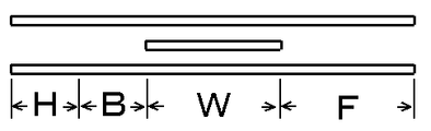
図10に示す合成樹脂発泡シートを用いて得られる凹凸型敷きマットは、人体の各部分に対応する部分の突出部2、3の剛性が、腰部W>頭部H、胸部B>脚部Fの順である。また、図11に示す合成樹脂発泡シートを用いて得られるマットは、人体の各部分に対応する部分の突出部の剛性が、腰部W>胸部B>脚部F>頭部Hの順である。
The uneven mattress obtained by using the synthetic resin foam sheet shown in FIG. 10 is such that the
次に、ポリウレタンフォームを用いた凹凸型敷きマット1の実施形態について以下に説明する。
本実施形態においては、多数の突出部はすべてが同一形状であり、長手方向及び幅方向に碁盤の目のように規則正しく整列して並んでいる。突出部は平面視円形で半球を上下方向に縮めたようなドーム型形状である。また、突出部は指圧効果が十分発現されるように40〜60mmの間隔(ピッチ)で並んでいる。さらに、突出部は、平面視直径が突出部の間隔(ピッチ)の1/2〜1であり、高さTが10〜20mmである。
Next, an embodiment of the
In the present embodiment, all of the plurality of projecting portions have the same shape, and are regularly aligned in a longitudinal direction and a width direction like a grid. The projecting portion is circular in plan view and has a dome shape that is a hemisphere contracted vertically. Further, the protrusions are arranged at intervals (pitch) of 40 to 60 mm so that the acupressure effect is sufficiently exhibited. Further, the protrusion has a diameter in plan view that is 1/2 to 1 of the interval (pitch) between the protrusions, and a height T of 10 to 20 mm.
突出部が中空突出部2の場合は、指圧効果を良好とするために、突出部厚さtが3〜7mm、密度が150〜400kg/m3の範囲にある。また、中実突出部3の場合は、指圧効果を良好とするために密度が80〜200kg/m3の範囲にある。
When the protruding portion is the hollow protruding
突出部2、3は、腰部に対応する部分Wのものが人体の他の部分に対応する部分のものと比較して以下のようにされていることが好ましい。
The
中空突出部2の場合は、中空突出部の厚さtの平均に中空突出部の密度の平均を乗じた算出値において、腰部に対応する部分Wが人体の他の部分に対応する部分に対して1.1〜1.4倍である。例えば、中空突出部の厚さtをすべて同一とした場合は、中空突出部の平均密度において、腰部に対応する部分Wが人体の他の部分対応する部分に対して1.1〜1.4倍である。算出値が1.1倍未満であると人体に対する指圧バランスの向上があまりなく、1.4倍を超えると指圧バランスが悪くなる傾向である。
In the case of the
中空突出部3の場合は、中実突出部の平均密度において、腰部に対応する部分Wが人体の他の部分に対応する部分に対して1.1〜1.4倍である。密度が1.1倍未満であると人体に対する指圧バランスの向上があまりなく、1.4倍を超えると指圧バランスが悪くなる傾向である。
In the case of the
本発明で使用するポリウレタンフォームの密度、硬度は、特に限定されないが、比較的低密度でかつ高硬度のものを用い、これを高い比率で圧縮すると突出部の剛性が高められる傾向にある。具体的には、密度15〜22kg/m3、硬度80〜130N(JIS K6400:D法)、総厚50〜120mmのものを、中空突出部の成形においては10〜25倍の圧縮度合い、中実突出部の成形においては5〜15の圧縮度合いで熱圧縮することが好ましい。ポリウレタンフォームの熱圧縮成形時の加熱温度は、成形効率、成形後の物性の点から160℃〜230℃とすることが好ましい。 The density and hardness of the polyurethane foam used in the present invention are not particularly limited, but if a polyurethane foam having a relatively low density and high hardness is used and compressed at a high ratio, the rigidity of the protruding portion tends to be increased. Specifically, a material having a density of 15 to 22 kg / m 3 , a hardness of 80 to 130 N (JIS K6400: D method), and a total thickness of 50 to 120 mm is used. In forming the actual protrusion, it is preferable to perform thermal compression at a compression degree of 5 to 15. The heating temperature at the time of hot compression molding of the polyurethane foam is preferably 160 ° C. to 230 ° C. from the viewpoint of molding efficiency and physical properties after molding.
次に、本発明の別実施形態の凹凸型敷きマットについて説明する。この凹凸型敷きマット及びその製造方法は、基本的な部分においては以上で説明した凹凸型敷きマットと同じである。また外観形状も図3に示すものと同じである。しかし、ここで説明する凹凸型敷きマットは、突出部が高い剛性の列及び低い剛性の列をなし、これらの列が交互に並んでいる態様である。 Next, the uneven | corrugated type | mold mat | matte of another embodiment of this invention is demonstrated. The concavo-convex mat and its manufacturing method are the same as the concavo-convex mat described above in the basic part. The external shape is also the same as that shown in FIG. However, the uneven-type mat described here is a mode in which the protrusions form a high-rigidity row and a low-rigidity row, and these rows are alternately arranged.
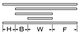
この凹凸型敷きマットの製造方法は、合成樹脂発泡シートとして、例えば図12に示すように、頭部から脚部までの部分(H、B、W、F)に対応する上下2枚の発泡シートの少なくとも一方に、互いに平行な凹条部6と凸条部7とによる凹凸の繰り返しを片面に有する凹凸発泡シート5を用い、図13に示すように、凹凸発泡シート5の凸条部7のピッチを第一型の凹部10のピッチの倍とし、凹凸発泡シート5の凹条部10と凸条部7とを第一型の凹部10のすべてに対峙させて熱圧縮成形するものである。
As shown in FIG. 12, for example, as shown in FIG. 12, the manufacturing method of this concavo-convex mat has two upper and lower foam sheets corresponding to portions (H, B, W, F) from the head to the legs. At least one of the concave and
凹凸発泡シート5としては、凹凸面が波状になだらかに形成されるためプロファイル裁断加工によって形成される発泡シートが好ましい。凹凸面がなだらかであることで、マット表面に筋状のものが現れにくいという効果がある。図13はプロファイル裁断加工によって得られる凹凸発泡シート、図14はプロファイル裁断加工の説明図である。
The
このようにして得られる本発明の凹凸型敷きマットは、これ自体あるいは20〜50mm程度の合成樹脂発泡体や固綿等の弾性体との積層体とされ、織布、編布、網布等からなるカバー材で被覆されて使用される。 The concavo-convex mat of the present invention thus obtained is itself or a laminate of about 20 to 50 mm of a synthetic resin foam or an elastic body such as solid cotton, and is woven, knitted, net cloth, etc. It is used by being covered with a cover material made of
合成樹脂発泡シートとして、ポリウレタンフォーム(密度18kg、硬さ90N)を用い、これを裁断して、図10に示すような発泡シートの組み合わせ(上から厚さ30mm、10mm、10mm、30mm)として構成し、接着剤にて各発泡シートを貼り合わせて、図1に示すような多数の凹部を有する型M1と多数の凸部を有する型M2とで熱圧縮成形して凹凸型敷きマット1を得た。型の温度は200℃とし圧縮時間は5分とした。 A polyurethane foam (density 18 kg, hardness 90 N) is used as the synthetic resin foam sheet, and this is cut to form a combination of foam sheets as shown in FIG. 10 (thickness 30 mm, 10 mm, 10 mm, 30 mm from above). Then, the foamed sheets are bonded together with an adhesive, and a heat proof molding is performed with a mold M1 having a large number of concave portions and a mold M2 having a large number of convex portions as shown in FIG. It was. The mold temperature was 200 ° C. and the compression time was 5 minutes.
得られた凹凸型敷きマット1は、碁盤の目のように並んだ中空突出部2を有するもので、基盤部4の厚さ;10mm、中空突出部2が半球を上下に縮めたようなドーム型形状であり、ピッチ;50mm、平面視直径;48mm、高さT;15mm、厚さt;4mm、頭部及び胸部に対応する部分H、Bの平均密度;240kg/m3、腰部に対応する部分Wの平均密度;280kg/m3、脚部Fに対応する部分の平均密度;205kg/m3であった。
The obtained
この凹凸型敷きマット1は、同等な圧力の荷重に対して、腰部に対応する部分Wの突出部2が最も変形せず、次に頭部H、胸部B変形せず、脚部Fが最も変形しやすいものであった。すなわち、突出部2の剛性は、腰部W>頭部H、胸部B>脚部Fの順であった。また、突出部の表面にアスカーC型硬度計を押しあてたときの硬度測定値は、腰部Wが50度、頭部H及び胸部がB40度、脚部Fが30度であった。
In the
図2に示すような多数の凹部を有する型と平坦な型を使用した以外は、実施例1と同様な手順で凹凸型敷きマット1を得た。
An
得られた凹凸型敷きマット1は、碁盤の目のように並んだ中実突出部3を有するもので、基盤部4の厚さ;5mm、中実突出部3が半球を上下に縮めたようなドーム型形状であり、ピッチ;50mm、平面視直径;48mm、高さT;15mm、頭部及び胸部に対応する部分H、Bの平均密度;100kg/m3、腰部に対応する部分Wの平均密度;115kg/m3、脚部に対応する部分Fの平均密度;90kg/m3であった。
The obtained
この凹凸型敷きマット1は、同等な圧力の荷重に対して、腰部に対応する部分Wの突出部2が最も変形せず、次に頭部H、胸部B変形せず、脚部Fが最も変形しやすいものであった。すなわち、突出部3の剛性は、腰部W>頭部H、胸部B>脚部Fの順であった。突出部の表面にアスカーC型硬度計を押しあてたときの硬度測定値は、腰部Wが15度、頭部H及び胸部Bが10度、脚部Fが5度であった。
In the
合成樹脂発泡シートとして、ポリウレタンフォーム(密度18kg、硬さ90N)を用い、これを裁断して、図12に示すような発泡シートの組み合わせ(上から厚さ20mm、10mm、10mm、凸条部が60mmで凹条部が30mmの凹凸発泡シート(プロファイル裁断加工品))として構成し、接着剤にて各発泡シートを貼り合わせた。凹凸発泡シートの凸条部のピッチは、第一型M1の凹部10のピッチの倍とした。次に、図13に示すように、凹凸発泡シートの凹条部6と凸条部7とを第一型の凹部10のすべてに対峙させて熱圧縮成形して、図3に示すような凹凸型敷きマット1を得た。型は200℃とし圧縮時間は5分とした。
A polyurethane foam (density 18 kg, hardness 90 N) is used as the synthetic resin foam sheet, and this is cut into a combination of foam sheets as shown in FIG. It was configured as a concavo-convex foamed sheet (profile cut product) having a grooved portion of 60 mm and a thickness of 30 mm, and each foamed sheet was bonded with an adhesive. The pitch of the ridges of the concavo-convex foam sheet was double the pitch of the
得られた凹凸型敷きマット1は、碁盤の目のように並んだ中空突出部2を有する基盤部4の厚さ;10mm、中空突出部2が半球を上下に縮めたようなドーム型形状であり、ピッチ;50mm、平面視直径;48mm、高さT;15mm、厚さt;4mm、頭部及び胸部に対応する部分W、Bの平均密度;260kg/m3、腰部に対応する部分Wの平均密度;295kg/m3、脚部に対応する部分Fの平均密度;230kg/m3であった。
The obtained
この凹凸型敷きマット1は、同等な圧力の荷重に対して、腰部に対応する部分Wの突出部2が最も変形せず、次に頭部H、胸部B変形せず、脚部Fが最も変形しやすいものであった。すなわち、突出部3の剛性は、腰部W>頭部H、胸部B>脚部Fの順であった。また、突出部は、幅方向に高い剛性の列及び低い剛性の列をなし、これらの列が交互に並んでいる。そして、突出部の表面にアスカーC型硬度計を押しあてたときの硬度測定値は、腰部Wにおいては剛性の高い列の突出部が70度、腰部Wの剛性の低い列の突出部が40度、頭部H及び胸部Bにおいては剛性の高い列の突出部が60度、腰部Wの剛性の低い列の突出部が30度、脚部Fにおいては剛性の高い列の突出部が50度、腰部Wの剛性の低い列の突出部が20度であった。
In the
M1 第一型
M2 第二型
H 頭部に対応する部分
B 胸部に対応する部分
W 腰部に対応する部分
F 脚部に対応する部分
1 凹凸型敷きマット
2 中実突出部
3 中空突出部
4 基盤部
5 凹凸発泡シート(プロファイル裁断加工品)
6 凹条部
7 凸条部
M1 1st mold M2 2nd mold H Part B corresponding to the head part W corresponding to the chest part F corresponding to the
6
Claims (2)
前記合成樹脂発泡シートは、頭部から脚部までの部分に対応する上下2枚の発泡シートの間に、腰部に対応する部分に別の発泡シートを配して積層したものであり、
腰部に対応する部分の突出部は、人体の他の部分に対応する部分の突出部より剛性が高くされていることを特徴とする凹凸型敷きマット。 A concavo-convex floor mat in which a synthetic resin foam sheet is hot-compressed to form a large number of protrusions,
The synthetic resin foam sheet is obtained by placing another foam sheet on the part corresponding to the waist part and laminating between the two upper and lower foam sheets corresponding to the part from the head part to the leg part,
An uneven mat, wherein the protrusion of the part corresponding to the waist is made more rigid than the protrusion of the part corresponding to the other part of the human body.
Priority Applications (1)
| Application Number | Priority Date | Filing Date | Title |
|---|---|---|---|
| JP2005316458A JP4724533B2 (en) | 2005-10-31 | 2005-10-31 | Uneven type mat and method for producing the same |
Applications Claiming Priority (1)
| Application Number | Priority Date | Filing Date | Title |
|---|---|---|---|
| JP2005316458A JP4724533B2 (en) | 2005-10-31 | 2005-10-31 | Uneven type mat and method for producing the same |
Publications (3)
| Publication Number | Publication Date |
|---|---|
| JP2007117581A JP2007117581A (en) | 2007-05-17 |
| JP2007117581A5 JP2007117581A5 (en) | 2008-12-04 |
| JP4724533B2 true JP4724533B2 (en) | 2011-07-13 |
Family
ID=38142054
Family Applications (1)
| Application Number | Title | Priority Date | Filing Date |
|---|---|---|---|
| JP2005316458A Active JP4724533B2 (en) | 2005-10-31 | 2005-10-31 | Uneven type mat and method for producing the same |
Country Status (1)
| Country | Link |
|---|---|
| JP (1) | JP4724533B2 (en) |
Cited By (1)
| Publication number | Priority date | Publication date | Assignee | Title |
|---|---|---|---|---|
| US8544427B2 (en) | 2010-03-17 | 2013-10-01 | Honda Motor Co., Ltd. | Cooling water passage structure in cylinder head of internal combustion engine |
Citations (8)
| Publication number | Priority date | Publication date | Assignee | Title |
|---|---|---|---|---|
| JPS53110676A (en) * | 1977-03-10 | 1978-09-27 | Kohkoku Chem Ind | Production of heat compressed foam sheet having hollow projection with different compression ratio |
| JPS53127796U (en) * | 1977-03-17 | 1978-10-11 | ||
| JPS5673833U (en) * | 1979-11-13 | 1981-06-17 | ||
| JPS5849968U (en) * | 1981-09-30 | 1983-04-04 | アキレス株式会社 | Pine tress base material |
| JPH10146247A (en) * | 1996-11-20 | 1998-06-02 | Tomoji Kobayashi | Cushion material |
| JPH10272036A (en) * | 1997-01-31 | 1998-10-13 | Achilles Corp | Mat for bedding |
| JP2000093263A (en) * | 1998-09-18 | 2000-04-04 | Osaka Nishikawa:Kk | Mattress |
| JP2000210162A (en) * | 1999-01-21 | 2000-08-02 | Osaka Nishikawa:Kk | Mattress |
Family Cites Families (2)
| Publication number | Priority date | Publication date | Assignee | Title |
|---|---|---|---|---|
| CH612776A5 (en) * | 1977-02-21 | 1979-08-15 | Systems & Technics Sa | |
| JPS5673833A (en) * | 1979-11-21 | 1981-06-18 | Hitachi Ltd | Structure of cathode of electron tube |
-
2005
- 2005-10-31 JP JP2005316458A patent/JP4724533B2/en active Active
Patent Citations (8)
| Publication number | Priority date | Publication date | Assignee | Title |
|---|---|---|---|---|
| JPS53110676A (en) * | 1977-03-10 | 1978-09-27 | Kohkoku Chem Ind | Production of heat compressed foam sheet having hollow projection with different compression ratio |
| JPS53127796U (en) * | 1977-03-17 | 1978-10-11 | ||
| JPS5673833U (en) * | 1979-11-13 | 1981-06-17 | ||
| JPS5849968U (en) * | 1981-09-30 | 1983-04-04 | アキレス株式会社 | Pine tress base material |
| JPH10146247A (en) * | 1996-11-20 | 1998-06-02 | Tomoji Kobayashi | Cushion material |
| JPH10272036A (en) * | 1997-01-31 | 1998-10-13 | Achilles Corp | Mat for bedding |
| JP2000093263A (en) * | 1998-09-18 | 2000-04-04 | Osaka Nishikawa:Kk | Mattress |
| JP2000210162A (en) * | 1999-01-21 | 2000-08-02 | Osaka Nishikawa:Kk | Mattress |
Cited By (1)
| Publication number | Priority date | Publication date | Assignee | Title |
|---|---|---|---|---|
| US8544427B2 (en) | 2010-03-17 | 2013-10-01 | Honda Motor Co., Ltd. | Cooling water passage structure in cylinder head of internal combustion engine |
Also Published As
| Publication number | Publication date |
|---|---|
| JP2007117581A (en) | 2007-05-17 |
Similar Documents
| Publication | Publication Date | Title |
|---|---|---|
| JP4956744B2 (en) | mattress | |
| CN103429120B (en) | The bedding that 4th district are reversible | |
| AU2006200597A1 (en) | Cushion Pad for Shoes | |
| JP2014512936A (en) | Tension reducing foam and mattress structure | |
| JP6116498B2 (en) | Mattress manufacturing method | |
| US20170049242A1 (en) | Under mattress support | |
| JP2016501672A (en) | Mobility enhancement mattress | |
| JP4724533B2 (en) | Uneven type mat and method for producing the same | |
| EP2373198B1 (en) | Body support with non-planar top surface | |
| WO2006063311A3 (en) | Honeycomb mattress support | |
| JP2007195701A (en) | Mattress | |
| CN208176410U (en) | A kind of mattress | |
| JP2016215003A (en) | mattress | |
| RU190839U1 (en) | MATTRESS | |
| JP3221097U (en) | Mattress block body and mattress | |
| JP6158854B2 (en) | Cushion member and cushion body | |
| JP2021115208A (en) | Cushion body | |
| TWI727574B (en) | Weaving structure | |
| RU92313U1 (en) | SPRINGLESS MATTRESS | |
| JP7381038B2 (en) | Method for forming depressions in firm cotton and method for producing firm cotton | |
| CN219249687U (en) | Mattress used on adjusting bed and adjusting bed | |
| JP2017125315A (en) | Soundproof floor material | |
| KR20200000628U (en) | 3 Layers Mattress | |
| JP3559677B2 (en) | Area heater | |
| JPH0618532B2 (en) | mattress |
Legal Events
| Date | Code | Title | Description |
|---|---|---|---|
| A521 | Request for written amendment filed |
Free format text: JAPANESE INTERMEDIATE CODE: A523 Effective date: 20081021 |
|
| A621 | Written request for application examination |
Free format text: JAPANESE INTERMEDIATE CODE: A621 Effective date: 20081022 |
|
| A977 | Report on retrieval |
Free format text: JAPANESE INTERMEDIATE CODE: A971007 Effective date: 20101102 |
|
| A131 | Notification of reasons for refusal |
Free format text: JAPANESE INTERMEDIATE CODE: A131 Effective date: 20110106 |
|
| A521 | Request for written amendment filed |
Free format text: JAPANESE INTERMEDIATE CODE: A523 Effective date: 20110307 |
|
| TRDD | Decision of grant or rejection written | ||
| A01 | Written decision to grant a patent or to grant a registration (utility model) |
Free format text: JAPANESE INTERMEDIATE CODE: A01 Effective date: 20110331 |
|
| A01 | Written decision to grant a patent or to grant a registration (utility model) |
Free format text: JAPANESE INTERMEDIATE CODE: A01 |
|
| A61 | First payment of annual fees (during grant procedure) |
Free format text: JAPANESE INTERMEDIATE CODE: A61 Effective date: 20110411 |
|
| FPAY | Renewal fee payment (event date is renewal date of database) |
Free format text: PAYMENT UNTIL: 20140415 Year of fee payment: 3 |
|
| R150 | Certificate of patent or registration of utility model |
Ref document number: 4724533 Country of ref document: JP Free format text: JAPANESE INTERMEDIATE CODE: R150 Free format text: JAPANESE INTERMEDIATE CODE: R150 |
|
| S531 | Written request for registration of change of domicile |
Free format text: JAPANESE INTERMEDIATE CODE: R313531 |
|
| R350 | Written notification of registration of transfer |
Free format text: JAPANESE INTERMEDIATE CODE: R350 |
|
| R250 | Receipt of annual fees |
Free format text: JAPANESE INTERMEDIATE CODE: R250 |
|
| R250 | Receipt of annual fees |
Free format text: JAPANESE INTERMEDIATE CODE: R250 |