JP4724516B2 - Image forming apparatus - Google Patents
Image forming apparatus Download PDFInfo
- Publication number
- JP4724516B2 JP4724516B2 JP2005281953A JP2005281953A JP4724516B2 JP 4724516 B2 JP4724516 B2 JP 4724516B2 JP 2005281953 A JP2005281953 A JP 2005281953A JP 2005281953 A JP2005281953 A JP 2005281953A JP 4724516 B2 JP4724516 B2 JP 4724516B2
- Authority
- JP
- Japan
- Prior art keywords
- recording material
- type
- light
- threshold
- image forming
- Prior art date
- Legal status (The legal status is an assumption and is not a legal conclusion. Google has not performed a legal analysis and makes no representation as to the accuracy of the status listed.)
- Expired - Fee Related
Links
Images


Description
本発明は、記録材の種類を判別可能な画像形成装置に関するものである。 The present invention relates to an image forming apparatus capable of discriminating the type of recording material.
複写機、レーザプリンタ等の画像形成装置は、潜像を担持する潜像担持体と、現像装置と、転写装置と、定着装置とを備えている。現像装置は、潜像担持体に現像剤を付与することにより潜像を現像剤像として可視化するものである。転写装置は、所定方向に搬送される記録材に、現像装置による現像剤像を転写するものである。定着装置は、転写装置によって記録材上に転写された現像剤像を、所定の定着処理条件にて加熱及び加圧することにより定着させるものである。 Image forming apparatuses such as copying machines and laser printers include a latent image carrier that carries a latent image, a developing device, a transfer device, and a fixing device. The developing device visualizes the latent image as a developer image by applying a developer to the latent image carrier. The transfer device transfers a developer image by the developing device onto a recording material conveyed in a predetermined direction. The fixing device fixes the developer image transferred onto the recording material by the transfer device by heating and pressing under predetermined fixing processing conditions.
かかる画像形成装置においては、例えば、画像形成装置本体に設けられた操作パネル等に記録材のサイズや種類(以下「紙種」ともいう。)がユーザによって設定される。その設定に応じて、定着処理条件、例えば定着温度や定着装置を通過する記録紙の搬送速度が設定されるように制御される。 In such an image forming apparatus, for example, the size and type (hereinafter also referred to as “paper type”) of a recording material are set by a user on an operation panel or the like provided in the main body of the image forming apparatus. In accordance with the setting, control is performed such that the fixing process conditions, for example, the fixing temperature and the conveyance speed of the recording paper passing through the fixing device are set.
画像形成装置としては、その内部に記録材を判別するセンサを有するものが知られている。例えば、記録材の表面画像をCMOSセンサによって撮像し、記録材の表面平滑度を検出する方法により記録材の種類を判別し、現像条件、転写条件あるいは定着条件を可変制御する。(特許文献1参照) As an image forming apparatus, an image forming apparatus having a sensor for determining a recording material is known. For example, a surface image of the recording material is picked up by a CMOS sensor, the type of the recording material is determined by a method of detecting the surface smoothness of the recording material, and development conditions, transfer conditions or fixing conditions are variably controlled. (See Patent Document 1)
さらに、前記記録材を判別するセンサに対向する位置に発光源を設け、透過光を検出することにより、透過光による記録紙の厚さを判別する装置が提案されている。(特許文献2参照) Further, there has been proposed an apparatus for determining the thickness of a recording paper by transmitted light by providing a light source at a position facing a sensor for determining the recording material and detecting the transmitted light. (See Patent Document 2)
しかしながら、記録材を判別するための閾値が固定されているため、市場にあるすべての記録材の種類を正確に検出することが、困難であった。 However, since the threshold value for discriminating the recording material is fixed, it is difficult to accurately detect all types of recording materials on the market.
そこで、本発明は、上記のような問題点を解決し、記録材の判別精度をより向上させることができる画像形成装置を提案することを目的とする。 Accordingly, an object of the present invention is to propose an image forming apparatus that can solve the above-described problems and can further improve the recording material discrimination accuracy.
上記の目的を達成するために本出願人が案出した本発明に係る画像形成装置は、記録材に光を発光する発光手段と、前記発光手段から記録材に照射された光を受光する受光手段と、前記受光手段により受光された光に応じた値と記録材の種類を判別するための閾値とを比較して、複数の記録材の種類を判別する制御手段と、前記制御手段の判別結果として、記録材の種類毎の枚数を格納する格納手段と、を有し、前記制御手段は、前記格納手段に格納された記録材の種類毎の枚数に応じて、記録材の種類を判別するための閾値を変動させることを特徴とする。
In order to achieve the above object, an image forming apparatus according to the present invention devised by the present applicant includes: a light emitting unit that emits light to a recording material; and a light receiving unit that receives light emitted from the light emitting unit to the recording material. means and, by comparing the threshold value for discriminating the kind of recording material and a value corresponding to the light received by said light receiving means, a control hand stage you determine the type of a plurality of recording materials, wherein said control means as the determination result includes a storage means for storing the number of each type of the recording material, wherein the control means, according to the number of each type of printing materials stored in the storage means, the type of the recording medium It is characterized in that the threshold value for discriminating between is varied .
ここで、前記制御手段は、前記閾値によって分けられ隣り合う第1の判別領域と第2の判別領域において、第1の判別領域で判別された記録材の枚数と第2の判別領域で判別された記録材の枚数とを比較し、第1の判別領域又は第2の判別領域のうち枚数の多い判別領域を元の判別領域より広げるように前記閾値を変動させるものであって良い。
Here, the control means discriminates between the first discriminating area and the second discriminating area which are separated by the threshold value, based on the number of recording materials discriminated in the first discriminating area and the second discriminating area. The threshold value may be changed so that the number of the discriminating regions of the first discriminating region or the second discriminating region is larger than the original discriminating region .
また、制御手段は、前記格納手段に格納された記録材の種類毎の枚数に係数を乗算した値に応じて、記録材の種類を判別するための閾値を変動させるものであってよい。
Further, the control means may vary a threshold for determining the type of the recording material in accordance with a value obtained by multiplying the number of the recording material types stored in the storage means by a coefficient .
また、前記制御手段は、記録材の種類毎の枚数として、普通紙の枚数をa、厚紙の枚数をb、グロス紙の枚数をc、光沢度判別閾値の算出に用いる係数をw 1 、w 2 、透過率判別閾値の算出に用いる係数をw 3 、w 4 、光沢度閾値変動範囲をR 1 、透過率閾値変動範囲R 2 とした際に、光沢度判別閾値r 11 、r 12 、透過率判別閾値r 21 、r 22 を以下の式、

Further, the control means sets the number of sheets for each type of recording material as “a” for the number of plain papers, “b” for the number of thick papers, “c” for the number of glossy papers, and w 1 , w 2. When the coefficients used for calculating the transmittance determination threshold are w 3 and w 4 , the gloss threshold variation range is R 1 , and the transmittance threshold variation range R 2 , the gloss discrimination thresholds r 11 and r 12 are transmitted. Rate discrimination thresholds r 21 and r 22 are expressed by the following equations:
また、前記受光手段は、前記発光手段から照射され記録材を反射した反射光、又は前記発光手段から照射され記録材を透過した透過光を受光するものであってよい。
The light receiving means may receive reflected light emitted from the light emitting means and reflected from the recording material, or transmitted light emitted from the light emitting means and transmitted through the recording material .
上記の目的を達成するために本出願人が案出した本発明に係る別の画像形成装置は、記録材に光を発光する発光手段と、前記発光手段から記録材に照射された光を受光する受光手段と、前記受光手段により受光された光に応じた値と記録材の種類を判別するための閾値とを比較して、複数の記録材の種類を判別する制御手段と、記録材の種類の情報を入力するための入力手段と、前記制御手段により判別された記録材の種類と、前記入力手段により入力された記録材の種類とが一致した一致回数と一致しなかった不一致回数を格納する格納手段と、を有し、前記制御手段は、前記格納手段に格納された前記一致回数及び前記不一致回数に応じて、記録材の種類を判別するための閾値を変動させることを特徴とする。
In order to achieve the above object, another image forming apparatus according to the present invention devised by the present applicant includes a light emitting means for emitting light to a recording material, and light received from the light emitting means to the recording material. light receiving means for, by comparing the threshold value for discriminating the kind of recording material and a value corresponding to the light received by said light receiving means, and control means for discriminating the type of a plurality of recording materials, serial Rokuzai The input means for inputting the type information, the type of the recording material determined by the control means, and the number of mismatches in which the type of the recording material input by the input means did not match Storage means for storing, and the control means varies a threshold value for determining the type of the recording material in accordance with the number of matches and the number of mismatches stored in the storage means. And
ここで、前記制御手段は、前記格納手段に格納された前記一致回数及び前記不一致回数に係数を乗算した値に応じて、記録材の種類を判別するための閾値を変動させるものであってよい。
Here, the control means may vary a threshold for determining the type of the recording material in accordance with a value obtained by multiplying the coincidence count and the mismatch count stored in the storage means by a coefficient. .
また、前記制御手段は、普通紙、厚紙、グロス紙の夫々の前記一致回数をm 1 、m 2 、m 3 、普通紙、厚紙、グロス紙の夫々の前記不一致回数をn 1 、n 2 、n 3 、係数を夫々λ i (i=1,2)、w ij (i=1,2、j=1〜3)、前記制御手段により判別された記録材の種類と、前記入力手段により入力された記録材の種類とが一致した回数の割合をp j =m j /(m j +n j )(i=1,2、j=1〜3)、前記制御手段により判別された記録材の種類と、前記入力手段により入力された記録材の種類とが一致しなかった回数の割合をp j =n j /(m j +n j )(i=1,2、j=1〜3)とした際に、閾値の変動量Δα、Δβを以下の式、
Further, the control means sets the number of coincidence of each of plain paper, cardboard, and glossy paper to m 1 , m 2 , m 3 , and sets the number of mismatches of plain paper, cardboard, and glossy paper to n 1 , n 2 , n 3 , coefficients λ i (i = 1, 2), w ij (i = 1, 2, j = 1 to 3), the type of recording material determined by the control means, and input by the input means P j = m j / (m j + n j ) (i = 1, 2, j = 1 to 3), and the ratio of the number of times of coincidence with the type of the recorded recording material, The ratio of the number of times that the type does not match the type of the recording material input by the input means is p j = n j / (m j + n j ) (i = 1, 2, j = 1 to 3) When the threshold fluctuation amounts Δα and Δβ are expressed as follows:
本発明によれば、上記のように構成したので、記録材の種類の判別精度をより向上させることができる。 According to the present invention, since it is configured as described above, it is possible to further improve the discrimination accuracy of the type of recording material.
<第1の実施の形態>
図1は本発明の第1の実施形態を示す。これは、画像形成装置の例である。記録材判別センサ200は、第1の照射手段であるLED201、第2の照射手段であるLED204、第1の読取手段であるフォトトランジスタ203、第2の読取手段であるフォトトランジスタ202を有している。発光素子駆動部305は、LED201、204を駆動し、メイン制御部306は発光素子駆動部305を制御する。信号処理部307は、フォトトランジスタ202、203からの出力値を16bitの分解能でA/D変換を行い、フォトトランジスタ202、203の出力値を演算する。例えば、出力値の演算は、記録材の光沢度を示す(正反射出力/乱反射出力)値と、記録材の光透過性を示す正透過出力値(フォトトランジスタ202の出力)と、を求める。
<First Embodiment>
FIG. 1 shows a first embodiment of the present invention. This is an example of an image forming apparatus. The recording
比較演算部308は、信号処理部307で行われた結果を基に、あらかじめメモリ309に格納されている設定値と比較演算を行う。メモリ309は、EEPROMのような不揮発メモリであり、記録材判別のための設定値が格納されている。メモリ309には、LED201に対しては、2種類の異なる発光光量値、LED204に対しては、1種類の発光光量値が格納されている。例えば、工場出荷時などに基準紙を用いて基準紙からの正反射光量、乱反射光量を検出しその結果からフォトランジスタ202,203のそれぞれに対する発光光量値をメモリ309に格納する。フォトランジスタ202,203のそれぞれに対して発光光量値を設定する理由として、受光素子の感度ばらつきを、発光光量を変えることでキャンセルすることができるからである。
The
また、LED204も同様に工場出荷時などに上記と同様の基準紙を用いて基準紙からの正透過光量を検出し、その結果から求めた発光光量値をメモリ309に格納する。
Similarly, the
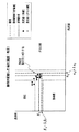
図2は図1の記録材判別センサ200の構成を示す。LED201を光源とする光は、スリット211を介して記録材搬送ガイド205上の記録材Pの表面に対し照射される。記録材搬送ガイド205は、本実施の形態では記録材の裏面側から光を照射するための窓を設けてある。記録材Pからの反射光は、スリット212、213を介し集光されてフォトトランジスタ202、203に受光される。これによって記録材Pの光沢度を検出する。
FIG. 2 shows the configuration of the recording
LED204を光源とする光は、光を集光させるためにある集光ガイド214を通って記録材Pの裏面へ照射される。記録材Pからの透過光は、スリット212、213を介してフォトトランジスタ202、203に受光される。これによって記録材Pからの透過光量を検出する。本実施の形態では、LED201は、LED光が記録材P表面に対し図2に示すように所定の角度をもって斜めより照射されるように配置されている。LED204は、LED光が記録材P裏面に対し、図2のように、フォトトランジスタ202の真下の位置から照射されるように配置されている。
Light using the
次に、記録材判別手順を説明する。ユーザにより、カセットトレイ(図示せず)やオプショントレイ(図示せず)やマルチトレイ(図示せず)に記録材がセットされた後、プリント開始コマンドをパソコンから受信すると、プリントを開始する。記録材判別センサ200の位置まで記録材が到達したら、記録材判別センサ200のLED201、204を、メモリ309に格納された発光光量値で発光させ、フォトトランジスタ202,203で反射光を受光する。LED204はLED201が消灯してからメモリ309に格納された発光光量値で発光させ、フォトトランジスタ202で記録材の透過光量を受光する。LED204が消灯した後、記録材判別閾値に基づいて、検出結果の値と比較演算を行う。その演算結果から、記録材の種類が確定する。
Next, a recording material determination procedure will be described. When the user receives a print start command from a personal computer after a recording material is set on a cassette tray (not shown), an optional tray (not shown), or a multi-tray (not shown), printing is started. When the recording material reaches the position of the recording
この比較演算による記録材の種類の確定手順について図3を参照して説明する。フォトトランジスタ202,203の出力値から求められた記録材の光沢度aと光沢度の判別閾値αとを比較演算する。
a>αである場合には、グロス紙と確定する。
a≦αである場合には、フォトトランジスタ202の出力値から求められた記録材の透過率bと透過率の判別閾値βとを比較演算する。
b>βである場合には、厚紙と確定する。
b≦βである場合には、普通紙と確定する。
The procedure for determining the type of recording material by this comparison operation will be described with reference to FIG. The glossiness a of the recording material obtained from the output values of the
When a> α, it is determined as gloss paper.
When a ≦ α, the transmittance b of the recording material obtained from the output value of the
If b> β, the paper is determined to be cardboard.
If b ≦ β, it is determined as plain paper.
次に、上述の記録材判別後に行う判別閾値の変動方法について説明する。図4は、初期状態における判別閾値と記録材の種類ごとの測定値分布とを示したものである。図4において、黒ドットが厚紙の測定値の分布を示し、グレードットがグロス紙の測定値の分布を示す。図5は変動後の判別閾値を示す。 Next, a method for changing the discrimination threshold performed after the above-described recording material discrimination will be described. FIG. 4 shows the discrimination threshold in the initial state and the measured value distribution for each type of recording material. In FIG. 4, black dots indicate the distribution of measured values for thick paper, and gradets indicate the distribution of measured values for glossy paper. FIG. 5 shows the discrimination threshold after fluctuation.
市場にある様々な種類の記録材の中には、図4で示したように紙種が異なるにもかかわらず測定値の分布が重なるものがあり、従来のように固定された閾値では、記録材を正確に判別することが困難である。そこで、同一種類の記録材が連続して通紙される可能性が高いことを利用する。 Among various types of recording materials on the market, there are those in which the distribution of measured values overlaps even though the paper type is different as shown in FIG. It is difficult to accurately identify the material. Therefore, the fact that there is a high possibility that the same type of recording material is continuously fed is used.
上述の記録材判別後に、図5のように記録材判別にて確定した記録材の種類(厚紙)を優先的に判別できるように、光沢度判別閾値及び透過率判別閾値を、予め紙種pごとに設定された変動量Δαp、Δβpだけ閾値を変動させる。すなわち、光沢度判別閾値を、初期閾値α0からα1(=α0+Δαp)に変動させる。また、透過率判別閾値を、初期閾値β0からβ1(=β0+Δβp)に変動させる。 After determining the recording material as described above, the glossiness determination threshold and the transmittance determination threshold are set in advance so that the recording material type (thick paper) determined by the recording material determination as shown in FIG. The threshold value is varied by the variation amounts Δα p and Δβ p set for each. That is, the glossiness determination threshold value is changed from the initial threshold value α 0 to α 1 (= α 0 + Δα p ). Further, the transmittance determination threshold value is changed from the initial threshold value β 0 to β 1 (= β 0 + Δβ p ).
2枚目の通紙に対しても、2枚目に通紙された紙種pに基づき、同様に、判別閾値をα2=α1+Δαp、β2=β1+Δβpと変動させる。3枚目以降も同様に通紙毎に検出された紙種に基づき閾値を変動させる。ただし、判別閾値は所定の範囲内でのみ変動可能である。 Similarly, for the second sheet, based on the paper type p that has been passed through the second sheet, the discrimination threshold is changed to α 2 = α 1 + Δα p and β 2 = β 1 + Δβ p . Similarly for the third and subsequent sheets, the threshold value is changed based on the paper type detected every time the paper is passed. However, the discrimination threshold can be varied only within a predetermined range.
このことにより、同一種類の記録材が通紙された場合に、安定して記録材を判別することを可能にする。さらに、複数枚の記録材を検出すると、閾値を跨いでしまい、同じ記録材をプリントしているにも関わらず、印字モードが突然変わるといった問題を低減することが可能となる。 This makes it possible to stably determine the recording material when the same type of recording material is passed. Further, when a plurality of recording materials are detected, it is possible to reduce the problem that the printing mode is suddenly changed although the threshold is exceeded and the same recording material is printed.
上述の閾値変動量は、記録材の種類ごと、給紙口ごとにそれぞれ設定されている。記録材は、一般的に、マルチトレイ、カセットトレイ、又はオプショントレイのうちのいずれかから給紙される。これらのトレイのうち、カセットトレイやオプショントレイは、100枚単位で記録材をセットすることが可能であるため、これらトレイからは、同じ種類の記録材が通紙される可能性が高い。一方、マルチトレイからは、様々な種類の記録材が給紙可能であるため、カセットトレイやオプショントレイに比べ、同一種類の記録材が連続している可能性が低い。このことから、カセットトレイやオプショントレイの閾値変動量を大きく設定し、マルチトレイの変動量を小さく設定する。閾値変動可能範囲も、給紙口により異なル用に設定し、カセットトレイやオプショントレイでは広い範囲に、マルチトレイではカセットトレイやオプショントレイよりも狭い範囲に設定されている。 The above threshold fluctuation amount is set for each type of recording material and for each sheet feeding port. The recording material is generally fed from either a multi-tray, a cassette tray, or an optional tray. Among these trays, the cassette tray and the optional tray can set recording materials in units of 100 sheets, and therefore there is a high possibility that the same type of recording material is passed from these trays. On the other hand, since various types of recording materials can be fed from the multi-tray, it is less likely that the same type of recording materials are continuous than the cassette tray or the optional tray. For this reason, the threshold fluctuation amount of the cassette tray and the option tray is set large, and the multi-tray fluctuation amount is set small. The range in which the threshold value can be changed is also set for different paper feed ports, and is set to a wide range for the cassette tray and the option tray, and to a narrow range for the multi-tray than the cassette tray and the option tray.
判別閾値は次の条件により初期値に戻る。当該プリントの検出結果の値と当該プリント直前の検出結果との差が所定以上の場合、誤検出の可能性が高いので、閾値を初期値に戻し、閾値変動の制御をはじめからやり直す。 The discrimination threshold returns to the initial value under the following conditions. If the difference between the value of the detection result of the print and the detection result immediately before the print is greater than or equal to a predetermined value, the possibility of erroneous detection is high, so the threshold value is returned to the initial value and the control of the threshold value variation is started again.
ユーザがカセットトレイ又はオプショントレイの開閉を行って、トレイに搭載された記録材枚数に変化が生じた場合には、ユーザにより記録材が補充もしくは交換が行われた可能性があるので、同様に、閾値を初期値に戻す。 If the user opens or closes the cassette tray or option tray and the number of recording materials loaded in the tray changes, the recording material may have been replenished or replaced by the user. The threshold value is returned to the initial value.
以上のように、本実施の形態によれば、記録材のばらつきによらず、記録材の判別精度を向上させることができる。 As described above, according to the present embodiment, it is possible to improve the recording material discrimination accuracy regardless of variations in the recording material.
<第2の実施の形態>
本実施の形態は、ユーザが利用する記録材の履歴を不揮発メモリに記憶し、該履歴に基づき記録材判別閾値を変更する例である。
<Second Embodiment>
The present embodiment is an example in which a recording material history used by a user is stored in a nonvolatile memory, and the recording material determination threshold is changed based on the history.
図6は、ユーザが利用した記録材の履歴を保存する手順に関するフローチャートである。第1の実施の形態と同様の記録材判別制御(S41)を行い、記録材の種類を確定する(S42)。記録材の通紙枚数を記憶するため、前記記録材判別後、記録材の種類ごとに通紙枚数を揮発メモリに格納する(S43)。電源オフ時にも記録材の通紙枚数を保持するため、所定枚数通紙されるごとか、あるいは、所定時間経過ごとに(S44)、揮発メモリに格納された枚数を、不揮発メモリであるメモリ309に書き込む(S45)。記録材判別閾値を、記録材の種類ごとの通紙枚数に基づき更新する(S46)。
FIG. 6 is a flowchart relating to the procedure for storing the history of the recording material used by the user. Recording material discrimination control (S41) similar to that of the first embodiment is performed to determine the type of recording material (S42). In order to store the number of passing sheets of the recording material, the number of passing sheets is stored in the volatile memory for each type of recording material after the recording material determination (S43). In order to hold the number of sheets of recording material to be passed even when the power is turned off, the number of sheets stored in the volatile memory is stored as a
続いて、上述の記録材履歴に基づいた記録材判別閾値の変更方法について説明する。図7は、判別閾値の変動量について説明したものである。電源オン時に上述により書き込まれた記録材通紙枚数を、メモリ309から読み込む。メモリ309には、出荷時に予め初期値が設定されている。プリント毎に記録材判別閾値が読み込まれた通紙枚数に基づき変動させる。なお、通紙枚数は上述と同様の手順でプリント毎に更新される。ここで、普通紙の通紙枚数をa、厚紙の通紙枚数をb、グロス紙の通紙枚数をcとする。そうすると、光沢度判別閾値は、次の式から、グロス紙の通紙枚数cとそれ以外の通紙枚数a+bの割合にそれぞれ重みw1、w2を加味し、光沢度閾値変動範囲R1をr11、r12の比重で分割することにより決定される。
Next, a method for changing the recording material determination threshold based on the above-described recording material history will be described. FIG. 7 explains the variation amount of the discrimination threshold. The number of sheets of recording material written as described above when the power is turned on is read from the
同様に、透過率判別閾値は普通紙の通紙枚数aと厚紙の通紙枚数bの割合に重みw3、w4を加味し、透過率閾値変動範囲R2をr21、r22の比重で分割することにより決定される。重みを加味しているのは、コストの高い紙種や画像形成が難しい紙種ほど検出されやすくするためである。これらの重みw1、w2、w3、w4は、前記のコストや画像形成特性等から予め最適化しておき、例えば不揮発性メモリ309に記憶しておけばよい。このような通紙枚数に基づく判別制御を行うことにより、通紙頻度が高い記録材の種類ほど検出されやすくなる。
Similarly, the transmittance determination threshold value is obtained by adding weights w 3 and w 4 to the ratio between the number of plain paper sheets a and the number of thick paper sheets b, and the transmittance threshold fluctuation range R 2 is a specific gravity of r 21 and r 22 . Determined by dividing by. The reason why the weight is added is to make it easier to detect high-cost paper types and paper types for which image formation is difficult. These weights w 1 , w 2 , w 3 , and w 4 may be optimized in advance from the above-mentioned costs, image forming characteristics, etc., and stored in the
以上より、ユーザの利用状況に応じた適正な記録判別制御を行うことが可能となる。 As described above, it is possible to perform appropriate record discrimination control according to the usage status of the user.
<第3の実施の形態>
本実施の形態は、ユーザが記録材の種類を指定する場合の例である。
<Third Embodiment>
The present embodiment is an example in which the user designates the type of recording material.
図8は、ユーザが紙種を指定するユーザ指定モードにおいて判別閾値の変更手順を示すフローチャートである。図9〜11は、ユーザ指定モード時の判別閾値のグラフを示す。ユーザが、プリント開始前にパソコンもしくはプリンタの操作パネル等を用いて、当該プリントの紙種を指定した後(S61)、図9のように初期閾値α0、β0を指定された紙種に適した初期判別閾値α1、β1に変更する(S62)。ここで、図9は厚紙が指定された場合の例である。この初期判別閾値α1、β1は紙種ごとに予め設定されている。このことにより、ユーザの指定した紙種に応じた記録材判別制御を行うことが可能となる。 FIG. 8 is a flowchart showing a procedure for changing the discrimination threshold in the user designation mode in which the user designates the paper type. 9 to 11 show graphs of the discrimination threshold value in the user designation mode. After the user designates the paper type of the print using the personal computer or the printer operation panel before starting printing (S61), the initial threshold values α 0 and β 0 are set to the designated paper type as shown in FIG. The initial determination threshold values α 1 and β 1 are changed to suitable ones (S62). Here, FIG. 9 shows an example in which a thick paper is designated. The initial determination threshold values α 1 and β 1 are set in advance for each paper type. This makes it possible to perform recording material discrimination control according to the paper type designated by the user.
プリント開始後(S63)、第1及び第2の実施の形態と同様な記録材判別制御を行い(S64)、紙種を確定する(S65)。紙種確定後、検出した紙種とユーザ指定の紙種が一致しているか確認する(S66)。 After the start of printing (S63), the same recording material discrimination control as in the first and second embodiments is performed (S64), and the paper type is determined (S65). After the paper type is determined, it is confirmed whether the detected paper type matches the paper type specified by the user (S66).
ユーザが指定した紙種と検出した紙種が一致しない場合について、図10を例に説明する。ユーザが指定した紙種と検出した紙種が一致しないことを、以下「メディア不一致」という。図10はユーザが厚紙を指定したにもかかわらず、測定値が普通紙の領域にある場合である。この場合、初期判別閾値α1、β1から検出紙種の判別領域が広くなるよう判別閾値α2、β2に変更する(S68)。このような制御を行うことにより、ユーザ指定の紙種をより検出しやすくなる。 A case where the paper type designated by the user does not match the detected paper type will be described with reference to FIG. The fact that the paper type designated by the user does not match the detected paper type is hereinafter referred to as “media mismatch”. FIG. 10 shows a case where the measured value is in the plain paper area even though the user has designated thick paper. In this case, the initial determination threshold values α 1 and β 1 are changed to the determination threshold values α 2 and β 2 so that the detection region of the detected paper type becomes wider (S68). By performing such control, it becomes easier to detect the user-specified paper type.
一方、ユーザが指定した紙種と検出した紙種が一致した場合について、図11を例に説明する。ユーザが指定した紙種と検出した紙種が一致したことを、以下「メディア一致」という。図11の例は、ユーザが厚紙を指定してなおかつ測定値が厚紙の領域にある場合である。この場合、検出紙種の判別領域が狭くなるように、初期判別閾値α1、β1から、判別閾値α3、β3に変更する(S67)。このときの変動量はメディア不一致時と比較して小さい。 On the other hand, a case where the paper type designated by the user matches the detected paper type will be described with reference to FIG. The coincidence between the paper type designated by the user and the detected paper type is hereinafter referred to as “media coincidence”. The example of FIG. 11 is a case where the user designates cardboard and the measured value is in the cardboard area. In this case, the initial determination threshold values α 1 and β 1 are changed to the determination threshold values α 3 and β 3 so as to narrow the detection sheet type determination region (S67). The amount of variation at this time is small compared to the case of media mismatch.
次に、ユーザによる紙種指定が無いオートモードにおける記録材判別閾値の変更方法について図12を用いて説明する。予め、ユーザ指定モード時に紙種ごとのメディア一致数(mj)とメディア不一致数(nj)を揮発メモリに格納する(j=1〜3)。ただし、普通紙、厚紙、グロス紙のメディア一致数をそれぞれm1、m2、m3、メディア不一致数をそれぞれn1、n2、n3とする。また、所定通紙枚数以上もしくは所定時間経過後、不揮発メモリにメディア一致数とメディア不一致数を書き込む。オートモード時において、次の式のように、判別閾値を、初期閾値α0、β0からα0+Δα、β0+Δβに変更する。 Next, a method for changing the recording material discrimination threshold in the auto mode in which the user does not specify the paper type will be described with reference to FIG. The number of media matches (m j ) and the number of media mismatches (n j ) for each paper type are stored in the volatile memory in advance in the user designation mode (j = 1 to 3). However, the media coincidence numbers of plain paper, thick paper, and glossy paper are m 1 , m 2 , and m 3 , respectively, and the media mismatch numbers are n 1 , n 2 , and n 3 , respectively. In addition, the media coincidence number and the media inconsistency number are written in the nonvolatile memory after the predetermined number of sheets have passed or a predetermined time has elapsed. In the auto mode, the discrimination threshold is changed from the initial thresholds α 0 and β 0 to α 0 + Δα and β 0 + Δβ as in the following equation.
ここで、λi(i=1,2)、wij(i=1,2、j=1〜3)は、重みである。また、変動量Δα、Δβは、当該プリント以前の各紙種毎のメディア一致の割合pj=mj/(mj+nj)と、メディア不一致の割合pj=nj/(mj+nj)とに、重みλi、wij、w′ijを加味して求めたものである。i=1,2であり、j=1〜3である。重みλi、wij、w′ijは、画像形成特性等から予め最適化しておく。このような制御を行う理由は、誤検出数がメディア不一致数に比例していると考え、誤検出を考慮した閾値変動を行うためである。 Here, λ i (i = 1, 2) and w ij (i = 1, 2, j = 1 to 3) are weights. Further, the fluctuation amounts Δα and Δβ are the media matching rate p j = m j / (m j + n j ) and the media mismatch rate p j = n j / (m j + n j ) before the printing. ) And the weights λ i , w ij , and w ′ ij . i = 1, 2 and j = 1-3. The weights λ i , w ij , and w ′ ij are optimized in advance from the image forming characteristics and the like. The reason for performing such control is that the number of false detections is considered to be proportional to the number of media mismatches, and threshold fluctuations are performed in consideration of false detections.
以上のように、本実施の形態によれば、ユーザ指定モード時の判別結果を利用することで、精度良く記録材を判別することができる。 As described above, according to the present embodiment, it is possible to accurately determine the recording material by using the determination result in the user designation mode.
なお、上述した実施形態では、記録材判別センサ200として発行素子であるLED201及び204、受光素子であるフォトトランジスタ202及び203とを有する構成で説明した。しかしこれに限らず、例えば、受光素子としてCMOSセンサを用いて所定範囲の映像を撮像して撮像した映像データに基づいて記録材の種類を判別するように構成しても良い。
In the embodiment described above, the recording
200 記録材判別センサ
201、204、301、302 LED
202、203、303、304 フォトランジスタ
211〜213 スリット
214 集光ガイド
305 発光素子駆動部
306 メイン制御部
307 信号処理部
308 比較部
309 メモリ
200 Recording
202, 203, 303, 304
Claims (8)
前記発光手段から記録材に照射された光を受光する受光手段と、
前記受光手段により受光された光に応じた値と記録材の種類を判別するための閾値とを比較して、複数の記録材の種類を判別する制御手段と、
前記制御手段の判別結果として、記録材の種類毎の枚数を格納する格納手段と、を有し、
前記制御手段は、前記格納手段に格納された記録材の種類毎の枚数に応じて、記録材の種類を判別するための閾値を変動させることを特徴とする画像形成装置。 A light emitting means for emitting light to the recording material;
A light receiving means for receiving light emitted to the recording material from the light emitting means;
Compares the threshold value for discriminating the kind of recording material and a value corresponding to the light received by said light receiving means, a control hand stage you determine the type of a plurality of recording materials,
As the result of the determination control means includes a storage means for storing the number of each type of the recording material, and
The image forming apparatus according to claim 1, wherein the control unit varies a threshold for determining the type of the recording material in accordance with the number of recording materials stored in the storage unit .
前記発光手段から記録材に照射された光を受光する受光手段と、
前記受光手段により受光された光に応じた値と記録材の種類を判別するための閾値とを比較して、複数の記録材の種類を判別する制御手段と、
記録材の種類の情報を入力するための入力手段と、
前記制御手段により判別された記録材の種類と、前記入力手段により入力された記録材の種類とが一致した一致回数と一致しなかった不一致回数を格納する格納手段と、を有し、
前記制御手段は、前記格納手段に格納された前記一致回数及び前記不一致回数に応じて、記録材の種類を判別するための閾値を変動させることを特徴とする画像形成装置。 A light emitting means for emitting light to the recording material;
A light receiving means for receiving light emitted to the recording material from the light emitting means;
A control unit for comparing a value according to the light received by the light receiving unit and a threshold for determining the type of the recording material, and for determining a plurality of types of the recording material ;
And input means for inputting information on the type of record material,
Storage means for storing the number of coincidence that did not coincide with the number of coincidence of the type of recording material determined by the control unit and the type of recording material inputted by the input unit ,
The image forming apparatus according to claim 1 , wherein the control unit varies a threshold for determining the type of the recording material in accordance with the number of coincidences and the number of mismatches stored in the storage unit .
Priority Applications (1)
| Application Number | Priority Date | Filing Date | Title |
|---|---|---|---|
| JP2005281953A JP4724516B2 (en) | 2005-09-28 | 2005-09-28 | Image forming apparatus |
Applications Claiming Priority (1)
| Application Number | Priority Date | Filing Date | Title |
|---|---|---|---|
| JP2005281953A JP4724516B2 (en) | 2005-09-28 | 2005-09-28 | Image forming apparatus |
Publications (3)
| Publication Number | Publication Date |
|---|---|
| JP2007093896A JP2007093896A (en) | 2007-04-12 |
| JP2007093896A5 JP2007093896A5 (en) | 2008-11-13 |
| JP4724516B2 true JP4724516B2 (en) | 2011-07-13 |
Family
ID=37979724
Family Applications (1)
| Application Number | Title | Priority Date | Filing Date |
|---|---|---|---|
| JP2005281953A Expired - Fee Related JP4724516B2 (en) | 2005-09-28 | 2005-09-28 | Image forming apparatus |
Country Status (1)
| Country | Link |
|---|---|
| JP (1) | JP4724516B2 (en) |
Families Citing this family (5)
| Publication number | Priority date | Publication date | Assignee | Title |
|---|---|---|---|---|
| JP5574233B2 (en) * | 2010-08-05 | 2014-08-20 | 株式会社リコー | Sheet supply apparatus and image forming apparatus |
| JP6212770B2 (en) * | 2013-04-24 | 2017-10-18 | コニカミノルタ株式会社 | Image forming apparatus |
| JP2019214185A (en) * | 2018-06-14 | 2019-12-19 | コニカミノルタ株式会社 | Paper kind detector, image formation device, image formation system, and program |
| JP7388042B2 (en) * | 2019-08-16 | 2023-11-29 | コニカミノルタ株式会社 | Image forming device, paper type determination method and program for the same device |
| US11500317B2 (en) * | 2020-01-21 | 2022-11-15 | Canon Kabushiki Kaisha | Image forming apparatus for controlling image forming condition based on recording material type |
Citations (2)
| Publication number | Priority date | Publication date | Assignee | Title |
|---|---|---|---|---|
| JPH09301561A (en) * | 1996-05-13 | 1997-11-25 | Konica Corp | Image recording device |
| JP2005037647A (en) * | 2003-07-14 | 2005-02-10 | Canon Inc | Image forming apparatus |
-
2005
- 2005-09-28 JP JP2005281953A patent/JP4724516B2/en not_active Expired - Fee Related
Patent Citations (2)
| Publication number | Priority date | Publication date | Assignee | Title |
|---|---|---|---|---|
| JPH09301561A (en) * | 1996-05-13 | 1997-11-25 | Konica Corp | Image recording device |
| JP2005037647A (en) * | 2003-07-14 | 2005-02-10 | Canon Inc | Image forming apparatus |
Also Published As
| Publication number | Publication date |
|---|---|
| JP2007093896A (en) | 2007-04-12 |
Similar Documents
| Publication | Publication Date | Title |
|---|---|---|
| JP4781191B2 (en) | Image forming apparatus and image forming method | |
| JP4663407B2 (en) | Recording material discrimination device and method | |
| US7110917B2 (en) | Abnormality determining method, and abnormality determining apparatus and image forming apparatus using same | |
| JP4724516B2 (en) | Image forming apparatus | |
| WO2009028731A1 (en) | Image forming device | |
| JP2006062842A (en) | Image forming device | |
| JP4810257B2 (en) | Image forming apparatus | |
| JP4640064B2 (en) | Image forming apparatus | |
| JP6263913B2 (en) | Image forming apparatus | |
| JP2008096617A (en) | Image forming apparatus | |
| US5483328A (en) | Toner supply control system and method | |
| JP2007206167A (en) | Image forming apparatus and control method therefor | |
| JP2008155482A (en) | Image printer and control method | |
| JP2007091393A (en) | Device and method for determining recording material | |
| JP7010091B2 (en) | Transport equipment, information acquisition methods and programs | |
| JP2009053387A (en) | Image forming apparatus | |
| JP2009058614A (en) | Image forming apparatus and image forming method | |
| US9873575B2 (en) | Image forming apparatus that displays remaining amount of sheets, control method therefor, and storage medium | |
| JP2007025114A (en) | Image forming apparatus | |
| JP4204739B2 (en) | Image forming apparatus, stop control method in image forming apparatus, and computer-readable storage medium storing program for executing the method | |
| JP2023011123A (en) | Image formation device and control program | |
| US9116454B2 (en) | Density detection apparatus and method and image forming apparatus | |
| JP2021181352A (en) | Sheet detector, sheet carrier and image forming apparatus | |
| JP2007153517A (en) | Recording material discriminating device and method | |
| JP4760529B2 (en) | Inkjet printer and image forming apparatus |
Legal Events
| Date | Code | Title | Description |
|---|---|---|---|
| A521 | Written amendment |
Free format text: JAPANESE INTERMEDIATE CODE: A523 Effective date: 20080926 |
|
| A621 | Written request for application examination |
Free format text: JAPANESE INTERMEDIATE CODE: A621 Effective date: 20080926 |
|
| RD02 | Notification of acceptance of power of attorney |
Free format text: JAPANESE INTERMEDIATE CODE: A7422 Effective date: 20101106 |
|
| A131 | Notification of reasons for refusal |
Free format text: JAPANESE INTERMEDIATE CODE: A131 Effective date: 20101126 |
|
| A521 | Written amendment |
Free format text: JAPANESE INTERMEDIATE CODE: A523 Effective date: 20110120 |
|
| TRDD | Decision of grant or rejection written | ||
| A01 | Written decision to grant a patent or to grant a registration (utility model) |
Free format text: JAPANESE INTERMEDIATE CODE: A01 Effective date: 20110401 |
|
| A01 | Written decision to grant a patent or to grant a registration (utility model) |
Free format text: JAPANESE INTERMEDIATE CODE: A01 |
|
| A61 | First payment of annual fees (during grant procedure) |
Free format text: JAPANESE INTERMEDIATE CODE: A61 Effective date: 20110411 |
|
| FPAY | Renewal fee payment (event date is renewal date of database) |
Free format text: PAYMENT UNTIL: 20140415 Year of fee payment: 3 |
|
| R150 | Certificate of patent or registration of utility model |
Free format text: JAPANESE INTERMEDIATE CODE: R150 |
|
| LAPS | Cancellation because of no payment of annual fees |