JP4722367B2 - Communications system - Google Patents
Communications system Download PDFInfo
- Publication number
- JP4722367B2 JP4722367B2 JP2001575003A JP2001575003A JP4722367B2 JP 4722367 B2 JP4722367 B2 JP 4722367B2 JP 2001575003 A JP2001575003 A JP 2001575003A JP 2001575003 A JP2001575003 A JP 2001575003A JP 4722367 B2 JP4722367 B2 JP 4722367B2
- Authority
- JP
- Japan
- Prior art keywords
- aircraft
- communication
- platform
- bandwidth
- ground
- Prior art date
- Legal status (The legal status is an assumption and is not a legal conclusion. Google has not performed a legal analysis and makes no representation as to the accuracy of the status listed.)
- Expired - Fee Related
Links
Images


Classifications
-
- H—ELECTRICITY
- H04—ELECTRIC COMMUNICATION TECHNIQUE
- H04B—TRANSMISSION
- H04B7/00—Radio transmission systems, i.e. using radiation field
- H04B7/14—Relay systems
- H04B7/15—Active relay systems
- H04B7/185—Space-based or airborne stations; Stations for satellite systems
-
- H—ELECTRICITY
- H04—ELECTRIC COMMUNICATION TECHNIQUE
- H04B—TRANSMISSION
- H04B7/00—Radio transmission systems, i.e. using radiation field
- H04B7/14—Relay systems
- H04B7/15—Active relay systems
- H04B7/185—Space-based or airborne stations; Stations for satellite systems
- H04B7/18502—Airborne stations
- H04B7/18506—Communications with or from aircraft, i.e. aeronautical mobile service
- H04B7/18508—Communications with or from aircraft, i.e. aeronautical mobile service with satellite system used as relay, i.e. aeronautical mobile satellite service
-
- H—ELECTRICITY
- H04—ELECTRIC COMMUNICATION TECHNIQUE
- H04B—TRANSMISSION
- H04B7/00—Radio transmission systems, i.e. using radiation field
- H04B7/14—Relay systems
- H04B7/15—Active relay systems
- H04B7/185—Space-based or airborne stations; Stations for satellite systems
- H04B7/18502—Airborne stations
- H04B7/18504—Aircraft used as relay or high altitude atmospheric platform
Description
【0001】
本出願は、ここに参照により本出願に組込む2000年4月10日申請の米国特許仮出願、一連番号60/196,058号の優先権を請求する。
【0002】
【発明の属する技術分野】
本発明は、無線通信システムに関し、詳細には航空機を用いる無線通信システムに関する。
【0003】
[発明の背景]
インターネット及びマルチメディアアプリケーションの急速な発展とともに、高バンド幅(帯域幅)、ラストマイル接続性をエンドユーザに提供するための課題が次第に増加している。このようなユーザに対しては、各種の異なる型の通信システムを通じて通信信号を送ることが出来る。有線の地上システムが一般的に、広バンド幅(帯域幅)通信のため高速通信を提供する。しかし、このようなシステムのための施設は、構築、保守及び更新のための費用が高く時間を要する上、それ自体では移動通信の助けにならない。送信塔を使用する無線システムは、供用地域面積当たりかなり局限されたバンド幅(帯域幅)のため、程々に高速の通信を提供する。
【0004】
地球静止軌道(GEO)衛星(高度約36,000キロメートル)もまたエンドユーザに無線通信を提供することが出来るが、バンド幅(帯域幅)効率の点で限界があるので、高人口密度地域で供用されている。地球中軌道及び低軌道(MEO及びLEO)衛星(それぞれ10,000キロメートル及び700〜1500キロメートル)システムは、エンドユーザ達が衛星の相対運動を追跡するための装置を有することを要求されるので、その性質上複雑である。さらに、GEO衛星は赤道軌道上になければならないので、その実用は赤道陸上地域に限定される。地球非静止衛星は、複雑な連続調整、指向性アンテナを、空中と陸上の双方に、一般には1つの通過衛星から次のものに通信信号を切り替えるのに適合させた副次系もともに、必要とする。もちろん、上記の衛星はいずれも、保守などのため、容易に回収することは出来ない。
【0005】
航空機は、旅客輸送、貨物輸送、消防、偵察、戦闘などを含む各種の用途に使われている。これらの用途が定める沢山の機能的役割を満足させるため各種の航空機がこれまで設計されて来た。これらの航空機の中には、在来の気球、飛行船、固定翼航空機、全翼機及びヘリコプタが含まれる。
【0006】
それを満足させるため、航空機がこれまでは一般的に設計されて来なかった機能的役割の1つは、航続距離が長く、副軌道(例えば、成層圏)上の、高々度の通信用プラットホームである。高々度プラットホームは、位置が比較的固定された高々度にとどまる航空機である。気球及び飛行船など空気より軽い航空機、及びヘリコプタは双方とも、高度限界及び強風下で選定局を維持する能力が欠けているので、高々度プラットホームとしての機能性に限界がある。一般的に高速で航行して高々度に到達しそれを維持する航空機は、無風状態で選定局を維持する能力が欠けているので、限界がある。さらに、ヘリコプタ、ある種の空気より軽い航空機及びたいていの航空機は、1週間以上又は1ヶ月などかなりの長期間はおろか、1日間以上にわたって高々度の局を維持することが出来ない。
【0007】
数多くの開発的航空機が、日中に大量の日光を浴びる限り太陽発電航空機として、昼夜の連続飛行を保つ可能性を有する。実際に建造されたこのような航空機3機が、パスファインダ、センチュリオン及びヘリオス航空機として良く知られており、数多くの飛行記録を樹立した。これら航空機の底流となる基本設計は、米国特許5,810,284号において詳細に論じられており、極めて高い縦横比及び比較的定常な翼弦と翼を有する無後退角全翼機を指向する。
【0008】
パスファインダ、センチュリオン及びヘリオス航空機など、副軌道上の高度で運航する長持続時間高々度プラットホームを、各種の機能で使用することが提案されて来た。一例として、マイクロ波通信装置を装備した高々度プラットホームは、遠隔地間の通信中継業務を提供することが出来る。その他の型の航空機は、重く高価で、しかも急速に消費される使用燃料の量が限られているので、この役割に最も適しているとは言えない。一般的に、これら他の型の航空機は、所望の位置にかなりの期間とどまることは出来ないので、これらの役割を果たすのに効用が限られる。
【0009】
【発明が解決しようとする課題】
高バンド幅(帯域幅)信号を固定位置及び移動受信機の双方に対して提供する通信システムを開発することが望ましい。本発明の各種実施例は、これら必要性の幾つか又は全部に合致することが出来る上、さらに関連の利点を提供する。
【0010】
【課題を解決するための手段】
本発明は、製造が安価で長期間にわたって空中にとどまることの出来る航空機を使用する通信システムを提供することにより上述の必要性を解決する。これらのシステムは、急速に配備することが出来、市場及び市場規模に対し伸縮自在で、新技術を用いて保守し更新することが出来る。性質上無線であるこれらのシステムは、可搬及び/又は移動ユーザに供用するため開発することが出来る。
【0011】
本発明は、地上局からの電波信号を、副軌道上の高度より上にある衛星又はその他の宇宙船に向かう光信号に転換するため使用することの出来る、副軌道上のプラットホームの使用を必然的に伴う。同様に、航空機は多数の地上局と結合して、広帯域及び/又は無線ネットワークを作成することが出来る。しかし、本航空機は衛星又は地球ラストマイル施設を生産するより遙かに廉価なだけでなく、回収可能で同一又は別の役割に使用することができる。
【0012】
本発明は、局が厳密に維持された成層圏プラットホームを、固定位置ユーザに対し効果的に対地不動の通信結節点として使用する。このプラットホームは、太陽エネルギと水素燃料電池のハイブリッドを用いて発生した電力により局維持を空気力学的に実現する。これらは、環境に優しく成層圏内に汚染物質を発生しない。ペイロードモジュールはその姿勢を保ち、ジンバルを用いてプラットホームの横揺れ−縦揺れ−首振り運動から切り離されている。ペイロードとユーザ端末双方のアンテナは、プラットホーム局維持力学に適合する設計となっている。
【0013】
データは、航空機に対しデータを放送し航空機からデータを受信する構成の地上に基地を置くゲートウエイを通じて処理することが出来る。プラットホームは、20KMの高度にある。これは、35,000キロメートル軌道にある静止衛星よりかなり近いので、与える遅延待ち時間は地球ネットワーク(回線網)と同等又はそれより良い。
【0014】
通信システムは、空間的に間隔を空けた複数の航空機を、周波数及び偏光の多様性とともに用いることが出来るので、222MHZ/KM2以上のバンド幅(帯域幅)密度効率を人口密度の高い都市領域にもたらすことが出来る。これはまた、競合システムを共存させることも出来る。
【0015】
本発明のその他の特徴及び利点は、添付図面との関連で取り上げた、好適実施例に関する以下の詳細説明から明らかになるであろう。ここでは、例を用いて本発明の原理を説明する。本発明の実施例を構築して使用することが出来るようにするため以下に説明する特定の好適実施例に関する詳細説明は、列挙した請求項の限定を意図するものではなく、請求発明の特定例として役立つこと意図するものである。
【0016】
【発明の実施の形態】
上記に要約し列挙請求項により定義される本発明は、添付図面との関連で読まれるべき以下の詳細説明を参照することにより、さらに良く理解されるであろう。本発明の特定の実施に関して構築し使用することが出来るように説明されている通信システムの特定好適実施例に関する以下の詳細説明は、列挙請求項の限定を意図するものではなく、それらの特定の例を提供することを意図するものである。
【0017】
[本発明のための好適航空機]
本発明は、地球に対しほぼ不動のプラットホームとして、局厳密維持要件を有する航空機の使用を含むのが好適である。本発明にしたがうと、好適航空機は、発明の背景の中で述べたように、パスファインダ、センチュリオン及びヘリオス航空機と類似の設計のものである。好適航空機の設計を以下に記述するが、更なる詳細は、参照によりここに組み込まれる米国特許5,810,284号に示されている。それでも、本発明用の別の航空機設計が、記述した航空機から大きく異なることもあるのは理解される筈である。
【0018】
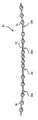
図1−3を参照すると、好適航空機実施例は、全翼機10である。即ちこれには胴体又は尾翼がない。その代わり、これは翼長に沿ってほぼ不変の翼形状と大きさを有する無後退角翼12を含む。6基、8基又は14基のモーター14が翼長に沿って色々な位置に置かれており、各モーターが単一プロペラ16を駆動して推進力を生じるのが好ましい。2個、4個又は5個の垂直羽根18a−18d、又はポッドが、その下端に着陸装置を付けて翼から下に伸びているのが好適である。
【0019】
好適航空機10は、太陽熱動力であって、燃料電池を含み昼夜の連続飛行用のためエネルギを蓄積する。これはしたがって、1週間乃至10日(例えば、200時間)及びさらに好適には3000時間以上にわたり連続して無人で飛行する使命に理想的に適している。あるいは、その電力の一部又は全部を、水素燃料(燃料電池又は在来モーターのいずれにも使用される液体水素など)、化石燃料その他の貯蔵燃料、もしくは日中は太陽エネルギ、夜間は再生不能又は一部再生可能貯蔵燃料など、燃料資源の組合せから、導き出す設計とすることが出来る。
【0020】
航空機10は、縦方向に翼長に沿って順に置かれた5個又は6個が好ましいモジュラー区画に分割する。これらの区画は、長さが39乃至43フィートの範囲で、約8フィートの翼弦長さを有する。こうして、航空機は、長さが約8フィートであり、好ましくは、翼長が約100、120、200又は250フィートとなるのが好適である。航空機の翼区画は飛行中に、区画間荷重が最小になるよう、それぞれの自重を支えるので、それにより必要な荷重負担構造体が最小になる。
【0021】
羽根(フィン)18a−18dは、区画の間の接続点で翼12から下向きに伸び、各羽根には、着陸装置の前方車輪及び後方車輪34、36が取り付けられている。この羽根は、電子回路(エレクトロニックス)、及び/又は各種ペイロードなど航空機の要素を中に収容するためのポッドとして構成されている。ポッドのうち1つ「コントロールポッド」は、主としてソフトウエアとして実現される自動操縦装置を含むモーターと昇降舵を制御するための制御用電子回路を搬送するため使われる。加えて、このポッドは、全地球測位システムを含むセンサと同時に下記に記述するような通信装置を運搬する。
【0022】
上述の設計の結果、航空機の好適実施例は、軽量(翼面積平方フィートあたり1ポンド以下)で、比較的遅い空中速度(低高度での13ノットから高々度での100ノットまで)で航行し空中にとどまるため、太陽電池のアレーから比較的少量の電力を必要とする。その局上での性能は、残りの通信システムに対し事実上透明(即ち、残りの通信システムは、航空機がその局を維持する限り、航空機の飛行により影響を受けない)であるようなものである。
【0023】
[地上リンクシステム]
図4A及び4Bは、本発明の通信システムを実施した第1のシステムのシステム概念を示す。このシステムは、通信結節点として使用される厳密に局を維持した成層圏プラットホームとして働く1機以上の航空機10、及びプラットホーム上と地上の双方に置かれた通信装置を含む。
【0024】
地上を基地とする通信装置は、1つ以上の「ゲートウェイ」102(即ち、1つ以上の航空機プラットホームに対し信号を放送及び/又は受信する地球上通信結節点)を含む。地上を基地とする通信装置はまた、それぞれが1つ以上のエンドユーザ位置106に端末アンテナ104を有する1つ以上のエンドユーザ端末(即ち、1人以上のエンドユーザのための通信装置)をも含む。端末アンテナはそれぞれ航空機プラットホームのうち1つに対して信号を放送及び/又は信号を受信することが出来る。多重端末アンテナは、単一ユーザのため異なる航空機からの信号にアクセスするため使用することができる、こうしてバンド幅(帯域幅)が増加する。
【0025】
ユーザ端末においてエンドユーザ106に対し又はエンドユーザ106から通信されるデータは、ゲートウエイ102とエンドユーザのユーザ端末との間で空中通信装置を経由して伝送される。詳細に説明すると、エンドユーザデータは、好適に処理されて1つ以上のゲートウエイトと1つ以上の航空機10との間で伝送される。
【0026】
航空機10は、移動しないゲートウエイ102及びエンドユーザ位置106に対し地球から見てほぼ不動に保たれる。詳細に説明すると、これらの航空機プラットホームは、端末アンテナ104のビーム幅の範囲内に保たれる。各プラットホームは、選択された通信領域又はセルの上で高度20KMの位置を保つのが好適である。これはあらゆる環境条件にわたって旋回半径600mで垂直高度±30メートルの内側にとどまるのが好適である。GEO衛星に比較して、この通信システムは、地上ネットワークと同等又はやや良好な遅延時間を有するであろう。
【0027】
空中通信装置は、航空機10の上の1つ以上のペイロードモジュール、及び好適にはポッド18(図1−3参照)の中で運搬される。この装置は、その姿勢を保ち、ジンバルを用いてプラットホームの横揺れ、縦揺れ、首振り運動から切り離される。空中通信装置(ペイロード)とエンドユーザ端末アンテナの双方は、航空機−プラットホームの局維持力学に適合する設計となっている。
【0028】
空中通信装置は、ユーザ端末アンテナの複数の異なるセル110に照準を合わせる構成となっている。六角が好適なこれらのセルは、航空機から適切な距離において、空中通信装置のバンド幅(帯域幅)と好適に釣り合いの取れた各種の大きさとすることが出来る。
【0029】
類似構成の通信装置を有する追加の航空機10は、最初の航空機によってサービス(役務提供)されているセル110に対し、及び/又は追加のセルに対し、追加のバンド幅(帯域幅)が備えられるようにする。各航空機は、互いの担当地上アンテナのビーム幅範囲内を飛行しないよう、相手側から距離を取らなければならない。この空間多様性はまた航空機をお互いの衝突から防護するのにも役立つ。
【0030】
システムは、空間多様性(密に詰まった、2次元の様々なプラットホーム位置からの、図4C参照)、周波数多様性、及び偏光多様性を用いて、222MHZ/KM2程度の高さのバンド幅(帯域幅)密度効率を人口密度の高い都市領域にもたらすことが出来る。密に詰まった空間多様性は、GEO衛星に関する軌道枠の1次元系よりかなり高いバンド幅(帯域幅)を与える。この空間多様性によりまた、競合システムが共存することが出来るようになる。
【0031】
ゲートウエイは、プラットホームへの上りリンクに92−95GHzを、プラットホームからの下りリンクに81−84GHzを使用する。周波数帯は、各ゲートウエイのため再使用された偏光である。自動追跡アンテナを有する空間的に分離された4個までのゲートウエイが、各プラットホームからのデータすべてを処理するのが好適である。全体再使用係数8が、プラットホーム当たり24GHzのバンド幅(帯域幅)処理能力を生じる。ゲートウエイは、ユーザデータを処理し、外部的に地球上及び/又は衛星ネットワーク(回線網)を通じるか、又は内部的に通信範囲内の宛先ユーザに対するプラットホームに上るかのいずれかでルートを定める。航空機に対するゲートウエイの通信リンクは、最悪の場合である雨中であってもリンクの性能を維持するようにクロスポラリゼーション相殺を用いるのが好適である。
【0032】
プラットホーム上の通信ペイロードは、ユーザをゲートウエイに対し接続するための単純な中継器設計である。ゲートウエイアンテナは、地上アンテナと相互に自動追跡する。ユーザリンク上でバンド幅(帯域幅)密度を得るには、多重ビームを在来の4セル再使用構成で配置する。セル大きさと端末間同期CDMA波形設計が、最悪の場合のプラットホーム運動が起こす干渉を克服する。
【0033】
エンドユーザ通信リンク(航空機からユーザ端末まで)は、Ka又はKu帯域用に設計することが出来る。図4Dは、GEO衛星Ka帯域を逆に、即ち19.7−20.2GHzをエンドユーザからの上りリンクに、29.5−30.0GHzをエンドユーザへの下りリンクに用いる当該設計を示す。利用可能の500MHZバンド幅(帯域幅)を、4セル再使用計画において2つの250MHZに分割する。24GHzゲートウエイ・バンド幅(帯域幅)全体を用いて、ペイロードは96個のユーザビームをサポートする。これは、相手先セルサイズが8KM六角形であるとき、6MHZ/KM2のバンド幅(帯域幅)密度を達成する。
【0034】
ユーザの端末アンテナは、プラットホームの局維持操作に適応するのに充分なビーム幅を有しなければならない。同時にこれらは、多数プラットホームが同一通信範囲の上で作動し、需要が増えたときさらにバンド幅(帯域幅)密度を向上することが出来るのに充分なだけ狭くなければならない。図4Dのペイロードに対応して、正規のE1(2,048MBPS)データ速度用のリンクに近づけるため、プラットホーム直下のセルについては径30cmのアンテナが使用される一方で、通信範囲縁辺のセルについては45cmアンテナが必要となる。Ka帯域におけるこれらアンテナのサイドローブレベルにより、図6に示すように、最小の相互干渉で37個のプラットホームの六方充填構造が可能になる。このことにより、重複領域におけるバンド幅(帯域幅)密度が222MHZ/KM2まで増加する。GEO Ka帯域端末とこのシステムとの間の干渉は、空間的分離を用いて大いに緩和することが出来る。
【0035】
1つ以上の運営センター100が飛行中の航空機プラットホームに命令し制御するのが好適である(図4B参照)。これらはまた、全体システム利用可能性を99.9%信頼度で保証するため、及び個別の航空機が保守される間システムを維持するため、代置して利用することの出来る追加の航空機プラットホームにも命令し制御する。運営センターは、下の地域のための適切な局に同時に維持することの出来る航空機プラットホームの船隊を制御するのが好適である。第1の航空機が第2のものに代置された後、第2の航空機は過酷な天候を避けるため遠隔地の着陸場に向かうことが出来るのが好適である。航空機の区画構造のため、及び区画の大きさのため、航空機はここで分解し、通常のトラックを用いて通信セルに近い滑走路に搬送することが出来る。
【0036】
システムは、各種マーケットに配置されたとき、大きさを完全に変更することが可能で、また多くの方法で最適化することが出来る。ペイロードは、単一ゲートウエイに対応して6GHz処理能力刻みで設計するのが好適である。アンテナビームは、必要なセル110をカバーするため選択的に配分する。
【0037】
ペイロード(即ち、空中通信装置)は、プラットホームを保守のため回収したとき、更新して再構成する。プラットホームは、小さいペイロードを用いて、より厳密に局を維持するため最適化することが出来る。これに対し、バンド幅(帯域幅)密度を高くするため、セルサイズを小さくすることがある。同様にシステム全容量もまた、通信領域をカバーする多数プラットホームを用いて維持することが出来る。
【0038】
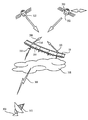
[衛星下りリンクシステム]
図5は、本発明を実施する第2の通信システムの概念を示す。この航空機10は、衛星など、衛星軌道高度以上に位置する宇宙船から、地上局に対し、高バンド幅(帯域幅)地対空通信システムを設定するため使用される。詳しく説明すると、航空機は、衛星302、地上局300、及びその間を移動する信号を支える通信装置を含む衛星下りリンクシステムの一部として働くのに特に良く適合されている。この型のシステムは、多種多様な通信システムの建設に有用なことがある。
【0039】
一般的に、地上局と衛星との間の通信には、雲などの各種大気現象を干渉なしで通過することの出来るマイクロ波信号など、或る種の型の電波信号を用いる。これらの信号の幾つかは多方向性で、幾つかは目標に対し与えられたビーム幅で向けられる。しかし、受信器感度と背景ノイズの与えられたレベルのため、特定のバンド幅(帯域幅)を搬送するのに必要な信号強度は、放送アンテナが比較的狭いビーム幅を有しているときであっても、地上局と衛星との間の距離とともに著しく増加する。受信器感度は、アンテナサイズを大きくして増加することが出来るが、衛星システムでは重いと費用がかかるので、アンテナ重量との兼ね合いがある。
【0040】
さらに、地球静止衛星の限られた例外のほか、衛星は、往復して赤道上を横切る地上軌跡を辿るので、これが地上局からの距離と方向の変動を生じ、指向性アンテナに(衛星から衛星への定期切り替えなど)大きい指向調節を必要とする。衛星(又は衛星群)の地上軌跡により、地上局は遠距離衛星との下りリンクを維持するため膨大な量の動力を必要とする。
【0041】
したがって、一般的に信号強度が、下りリンクに利用することの出来るバンド幅(帯域幅)に対する制限要因となり、指向性地上局に関しては、一般的に指向性アンテナが目標追跡能力を有しなければならない。さらに、信号強度を増加し得る範囲で、その増加によりその信号から著しい干渉を受ける地理的面積が広くなる。信号が広いビーム幅を有するか又は(セルラー通信に使われるもののように)多方向性であるときは、とりわけ著しい。要約すると、通信バンド幅(帯域幅)は、地上局上の衛星高度、地上局と衛星との間の最大地上距離(即ち、緯度及び経度の度数差)、受信器感度(アンテナサイズからなど)、ビーム幅、及び電力レベルにより制限される。加えて、少なくとも幾つかの用途においては、通信バンド幅(帯域幅)は背景ノイズ及び別の位置の信号との許容干渉に関する限界により制限される。さらに、電力要件軽減のため狭ビーム幅地上局アンテナを使用するときは、著しい費用が課せられ、追跡要件の精度のため、余計な故障の危険性を生じることがある。
【0042】
衛星対衛星通信信号、又は衛星対非軌道宇宙船上りリンクは、レーザその他の光信号など高周波信号を使って、限られた電力で遠距離にわたって広バンド幅(帯域幅)を達成することが出来るので、これらの型の束縛を受けるとは限らない。これらの信号は、雲などの大気現象を通過するとき急速に劣化することがある。したがって、このような高周波通信信号は、一般的に衛星間通信、又は衛星と雲などの大気現象に直面しそうにない地上位置との間の通信に限られる。
【0043】
本発明の好適実施例は、マイクロ波信など地上局300からの電波信号を、衛星又はその他の宇宙船に向けた光信号に変形するため、副軌道上のプラットホーム304を備えることにより、地対空通信バンド幅(帯域幅)に著しい増加を与えることが出来る。この通信リンクはいずれの方向にも向けることが出来るが、この通信リンクは双方向性であるのが好ましい。
【0044】
この機能のため、副軌道上の好適プラットホーム、本発明の航空機10は、地上局にある上向き指向性アンテナの付いたマイクロ波送受信器312と交信する下向き指向性アンテナの付いたマイクロ波送受信器310、及び衛星にある下向き指向性アンテナの付いた光送受信器316と交信する上向き指向性アンテナの付いた光送受信器314を含む。航空機は、雲318及びその他の大気湿度など大気の著しい光干渉のため、一般的高度の上の高度まで上げるのが好適で、地上局と航空機との間の信号バンド幅(帯域幅)を最大にするのに充分なだけ低いのが好適である。航空機は、それぞれが地面を向いた照準可能であるのが好ましい複数のアンテナを、地上局用に有するのが好適である。
【0045】
航空機は、高度50,000フィートと70,000フィートとの間で、200時間以上(更に、好適には300時間以上)運航するのが最も好適である。この航空機を使って作られた通信システムは、地上と低軌道高度との間の距離を超える広範囲の通信(即ち、広いバンド幅(帯域幅)の通信)を妨げる地上局マイクロ波電力レベルで働くのが好適である。
【0046】
航空機は、地面に対し比較的静止した位置にとどめて、地上局が航空機を追跡する必要性を局限するか又は除去するのが好ましい。詳細に説明すると、航空機は径7000フィートの円形で高度範囲1000フィートで運航するのが好適で、ほぼ径4000フィートの円内又はその近傍で運航するのがさらに好適である。さらに、航空機は垂直範囲1000フィート、さらに好適には垂直範囲100フィート以内又はその近傍で運航するのが好ましい。
【0047】
地上局300からの電波信号306を、光信号308を使って衛星302まで中継するため、副軌道上のプラットホームとして働く航空機は、多数の利点を提供し、各種の使命を実行することが出来る。例えば、このような航空機は、機械的不具合を起こしたとき迅速に交換することが出来る。同様に、このような航空機は、高電力レベルでは(広バンド幅(帯域幅)又は双方向信号のため)互いに干渉するかも知れない周波数を使いながら、互いに比較的近い距離以内で運航することが出来る。航空機それぞれに対する電波信号は、軌道にある衛星に対し同様のバンド幅(帯域幅)を与えるのに必要な電力レベルより著しくに低い電力レベルのものだからである。これは、各種信号のため必要なレベルまで電力使用を最小にするための閉ループ信号強度制御システムについて、さらに論じることが出来る。
【0048】
局限されたビーム幅を有する上向き指向地上アンテナ及び/又は下向き指向衛星アンテナの使用により、電力使用をさらに少なくすることが出来る。これら照準可能アンテナの各々は、航空機がとどまらなければならない空域の境界を定める。上向き指向地上アンテナと下向き指向衛星アンテナの双方を使うときは、照準を定めて、航空機が局維持飛行パターンを維持することの出来る空域の範囲を互いに区切らなければならない。
【0049】
境界の定まった空域内に局を維持するため、航空機は低速飛行航空機であるのが好適である。飛行パターンは一般的に、一定量の許容垂直変動を有するほぼ円形の錠剤型である。しかし、強風状態の下では、飛行機が概ね風上方向に向かって前後に進路を変えるジグザグのパターンから、一直線の風上向け飛行に、好適飛行パターンを変えることがあるのは理解される筈である。
【0050】
航空機は、単一地上局と、地球静止(又はその他の地球同期)衛星などの単一宇宙船との間の交信を円滑にするため働き、又は、図5に示すように、航空機の光通信の範囲内を順に通過する一連の低軌道衛星と交信することが出来る。衛星間を切り換える設計の航空機は、第1衛星302との通信リンクを切断する前に第2衛星322との通信リンクを捕捉するよう、2つの光通信装置314、320を含むのが好適である。
【0051】
図6に示すように、本発明を具体化する別の実施例においては、航空機10を、通信衛星への常時かつ直接のアクセスが別途の方法では容易には得られない北寄り又は南寄りの緯度で使用することが出来る。航空機を適切な副軌道上の(成層圏が好適)高度にとどめることにより、航空機は、緯度で80度以上離れた衛星324−−赤道により近く位置するであろう衛生−−との交信を設定することが出来る。
【0052】
関連する観点で、航空機は、赤道衛星に向けられた波長を再使用する指向性信号を使うことにより、たいていの如何なる非赤道局の長所を有利に利用することが出来る。詳細に説明すると、特定の地上局は、同一波長を用いて2つの異なる信号を、1つは地球静止衛星に向け他は航空機に向け、指向して放送することが出来る。非赤道衛星と異なり、航空機は赤道を横切る必要がないので、地上局は(地上局が衛星を切り換えなければならないとき起こるように)定期的に新しい放送方向に切り換える必要がない。当然の結果として、所与の航空機位置に関しては、衛星に対して放送するのと同じ周波数で、幾つかの地上局が放送することは出来ない。2つの指向性信号が重なり合うからである。例えば、航空機が赤道のやや北側にあり、地上局が赤道から遙か遠くの北にあるときは、信号が重なり合う。しかし、赤道から著しく離れた地上局のため、航空機を赤道上で衛星の遙か下にとどめることは可能であろう。本発明のこの側面は、配備された地上局が、空間的に分離した2機の航空機に放送することにより、バンド幅(帯域幅)を増加させるという本発明の第1実施例に関連することに注意すべきである。
【0053】
図7に描くように、通信システムの1実施例は、山岳325及びその他の障害物を迂回するため使用することが出来る。この特徴は、地上局を衛星に連結するため、及び同様に地上局を地上局に連結するため利用することが出来る。これは、地上局も衛星も莫大な労力及び/又は費用無しで一般的に再配置可能でないので、このシステムの特に効果的な使用法である。このようなシステムに関する効果的であるかも知れない用途の1つは、テレビ信号など広く放送される信号への障害の影響を克服することである。これらテレビ信号の信号源は、地上局、衛星又は別の航空機であることさえもある。別の効果的であるかも知れない用途は、同一周波数を使用する多数の地理的に分離された地上局に対する放送における周波数再使用である。これは、衛星が、遠く離れているので、同一周波数を使用する2つの地上局と別々の通信をするためには、狭いビーム幅を必要とする点で有利である。
【0054】
本発明の別の実施例は、航空機を、スポットビームに置かれたエンドユーザと、通信ネットワーク(回線網)との間で通信を中継する、地域ハブとして働かせるため使用する。通信ネットワーク(回線網)は地上アンテナを経由してアクセスする地球を基盤とするものでも、光又は超高周波マイクロ波リンクを経由してアクセスする宇宙を基盤とするものでもいずれでも良い。
【0055】
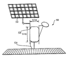
図8に描くこのような中継システムの1つは、航空機10を、地上局326と複数の衛星328との間で同時に交信する通信ハブとして用いる。この使命において、航空機は多数の光送受信器を必要とし、送受信器を作動させるため追加電力を発生する必要があるであろう。代替案として、図9及び10に描くように、それをカバーする通信範囲を備えた1機の航空機を持つ2つの通信範囲領域が示されている。詳細に説明すると、1機以上のこのような航空機10はすべて、単一衛星330と交信することが出来るので、1つ以上の地上局を通信ハブとして働く単一衛星に接続することが出来る。これは、各航空機による周波数再使用を提供し(即ち、利用することの出来る周波数の同一の組を各航空機が使用することが出来る)衛星と地上との間で利用することの出来るバンド幅(帯域幅)を増加するかも知れない。
【0056】
この筋書きは、人口密度の高い地域と衛星との間(図10参照)又は衛星と2つの離れた位置との間(図9参照)に与えるバンド幅(帯域幅)を増加することが出来る。前者の筋書きは、衛星と都市との間に極めて大量のデータ受け渡しを提供する。これは、低い周波数を地上近くで、及び光又は超高周波マイクロ波リンクを航空機と衛星との間の交信のため再使用するため異なる経路を提供する。この衛星は、次には、ハブとして働いて、これもまた地上通信のため副軌道上のプラットホームを使用することの出来る1つ以上の衛星334と交信する。加えて、航空機対航空機の直接交信をも使用することが出来る。これらの例が示すように、航空機は各種の通信システム構造の一部として役立つことが出来る。
【0057】
上述の好適実施例では、マイクロ波と光信号を使ったけれども、このシステムは各種各様の信号に関して働くことが出来ることは理解される筈である。詳しく説明すると、大気湿度が約1ミリメートル以下の電波波長(即ち、20ギガヘルツ以上の高周波信号)には著しく干渉するが、長い波長(即ち、20ギガヘルツ以下の低周波信号)にはそれ程でないことが知られている。したがって、このシステムは、1ミリメートルより大きい波長を有する地上局対航空機電波信号と、1ミリメートルより小さい波長を有する航空機対衛星電波を使って、好適に働かせることが出来る。さらに、上記発明の航空機を信号の向け直し及び/又は増幅に用いて、システムの航空機対衛星部分が、システムの地上局対航空機部分で使用されると同じ信号など、大気擾乱を通過する信号を用いて運営されるときであっても、電力を節約することが出来る。
【0058】
[広域配置システム]
図11Aを参照すると、本発明の第1実施例に関連する通信システムが、無線ローカル・ループ、ブロードバンド及び/又はその他の通信ネットワーク(回線網)の一部となっている。
【0059】
移動及び住宅用音声電話、移動及び住宅用インターネットアクセス、及びブロードバンドデータアクセスなど、各種形態の通信は、それぞれ異なる伝送要件を有する。例えば、音声電話は、比較的低いレベルのバンド幅(帯域幅)(4乃至64KBpsなど)を長時間(2乃至30分など)必要とし、インターネットアクセスは、大きいバンド幅(帯域幅)(64乃至2000KBpsなど)を極めて限られた時間(数秒間など)必要とし、ブロードバンドアクセスは、ほとんど連続的な基準で大きいバンド幅(帯域幅)(1Mビット以上など)に基づく。
【0060】
このような通信要件を与えるため、各種各様のネットワーク構造が一般的に開発され、各種形態のネットワーク(回線網)を導き出した。それらの中には、陸上回線電話ネットワーク(回線網)、セルラー・ネットワーク(回線網)、無線ローカル・ループ、及び各種の成層圏衛星基地ネットワーク(回線網)がある。
【0061】
一般的に、これら技術の各々を支えるには異なる装置を必要とする。しかし、場合により、このようなネットワーク(回線網)は1つ以上の機能を果たすことが出来る。例えば、ブロードバンド技術は、地上回線を経由して渡されるASDL(非対称デジタル加入者回線)技術の使用により固定位置エンドユーザにもたらすことが出来る。それでも、これら形態の異なるネットワーク(回線網)のほとんどは一般的に、いずれかのユーザ又はセルラタワーと相互接続するには、膨大で高価な回線の施設を必要とする。
【0062】
ネットワーク(回線網)に衛星を使用すると、一般的に、高密度領域の中のユーザに対し多重アクセスを提供することに困難がある。衛星に使用するための重量と動力に対する厳重な要件に合致する装置の開発には高い費用が掛かる。さらに、理想より劣る位置であって移動ユーザが行くのを選ぶことの出来る場所に対する送信のため必要な周波数再使用と余剰電力余裕が限られているため、運営維持が困難である。さらに、大気湿度又はその他の擾乱を貫通することが出来ないため周波数のかなりの帯域を使用することが出来ない。
【0063】
セルラー及びPCSシステムは、超過電力の使用及びかなりの周波数再使用を通じて建物内及び到達困難な場所への侵入において優れている。しかし、これらのシステムは、基地局及び/又は送信塔との間にかなりの広帯域接続性を必要とする。
【0064】
上述のような理由のため、既存施設のない地域、又は使用のため利用することの出来ない私有施設を有する地域に初めて展開するのは通信会社にとって困難である。本発明は、各種の実施例でこれらの懸念の1つ以上に対処する革新的ネットワーク(回線網)構造を提供する。
【0065】
図11Aで分かるように、本発明のこの実施例は、固定地上位置の間に広帯域一点対多点接続性を提供するため、航空機であるのが好適な(太陽熱又は在来の、有人又は無人)1つ以上の高々度プラットホームの使用を含む。代替案として、近地球軌道(NEO)衛星を使うこともある。この高々度プラットホームは、上述のように、1つの局の上又はその近くで地面に対し周回するか又は位置を保つ航空機であるのが好適である。
【0066】
航空機は、副軌道上のプラットホーム基地局として働き、一般的には固定地上位置にあり、加入者の商業ビル502及び加入者住居ビル504の屋根を含むこともある各種地上局500に対し及びその間に、好適には広帯域通信信号を維持する。地上局の少なくとも幾つかは、データ又は音声チャンネルを、一般的には地方の固定又は移動ユーザである1つ以上の遠隔加入者局に対して、配当する基地局として構成するのが好適である。地上基地局は、建物に加えて、街路灯506、看板、独立塔508又はその他の構造体の中に組み込むかその上に取り付けることが出来る。加入者基地局(商業用及び住宅用双方)もまた、有線又は無線接続により、その近傍の加入者のアクセスポートにネットワーク(回線網)接続するのが好適である。PSTN(公衆交換電話回線網)、PLMN(公衆陸上移動回線網)など他のネットワーク(回線網)又はインターネットに対する連結は、別の地上局510、衛星ネットワーク(回線網)512、又は加入者基地局においてこのようなネットワーク(回線網)へのアクセスリンクが利用出来る場合は既存加入者基地局を通じるアクセスにより設けることが出来る。
【0067】
図11Bに描くように、加入者の地上基地局500は一般的に、航空機と広帯域又は無線ループ連結を維持するためアンテナ520を付けて構成する。任意選択で、ソーラーアレ522を使い、加入者基地局が電源接続524を通じて引き出す電力を最小にすることが出来る。個別の加入者又は多数の加入者に役立てるため、各種形態の地上基地局を構成することが出来る。移動であろうと、地上基地局の地元領域内の固定であろうと、別の加入者のため働くには、固定位置に達するための有線ネットワーク(回線網)を使うことが出来るけれども、無線ローカル・ループを使うのが好適である。別の遠隔の加入者と交信するため、加入者基地局は、関連遠隔加入者局が選んだ無線規格に適切なアンテナ526を有するのが好適である。一例として、遠隔加入者局は、さもなければ加入者基地局、その関連加入者、及び居住建物に無関係の加入者が所有する、コードレス電話であることもある。
【0068】
無線ローカル・ループを含む各種各様の通信規格は、加入者基地局(又はその他の地上基地局)の遠隔加入者局を有する加入者に対する連結に使用することが出来る。互換性のある無線通信規格には、AMPS(最新移動電話サービス)、TACS(全アクセス通信システム)、NMT(スカンジナビア移動電話システム)、IS−95(コード分割多重アクセス米国デジタルセルラー規格)、IS−54/IS−136(米国セルラー規格、D−AMPSとも言う)、B−CDMA(ブロードバンドコード分割多重アクセス)、W−CDMA(ワイドバンドコード分割多重アクセス)、UMTS(ユニバーサル移動電気通信サービス)又はその他の3G、PHS(簡易型携帯電話)、DECT(デジタル強化コードレス電話)、PACS(個人最新通信システム)、PDC(個人デジタルセルラー)、CDPD(セルラーデジタルパケットデータ)、Mobitex(無線パケット回線網用エリクソン規格)及びRD−LAP(モトローラ開発無線パケット回線網)である。したがって、音声電話、e−メール、インターネットアクセス、ファクシミリ、ビデオ電話、及びビデオ会議を含む各種のサービスをこれら加入者に送信することが出来る。
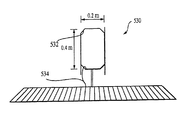
【0069】
図11Cに描くように、加入者遠隔局530には、加入者遠隔局の関連地上基地局が使用する無線規格に適合したアンテナ532を好んで含むであろう。これらの加入者遠隔局は、加入者の個別装置に対し、有線又は無線のネットワーク(回線網)接続534を有するであろう。
【0070】
この流通システムに関する上の記述から分かるように、本発明のこの側面は、高価な施設を据え付けることなく情報流通システムを提供する。代わりに、このシステムは、加入者又は他の地上局とともに置かれた個別の加入者基地局、及び地上局に対し及びその間の通信連絡を提供する、好適には高々度で、副軌道上の1つ以上のプラットホームのみを必要とする。
【0071】
上に記述した実施例をさらに裏付けして、幾つかの優先パラメータには下記が含まれる。
【0072】
−航空機は、通常航路及び荒天より上で、最大強風が、低いジェット気流領域より遙かに低速である60,000−70,000フィート領域で運航する。
【0073】
−航空機には、太陽熱電力、蓄電池、もしくは燃料電池、内燃機関又はタービンを通じて電力又は機械力を作るため燃焼させる燃料など、任意の適切な手段で動力を与える。
【0074】
−航空機は、比較的低速の飛行、厳密な局維持のための長期持続飛行と操縦性の双方に関する要件を満たす能力がある。
【0075】
−空中安定プラットホーム(方向と姿勢で安定)の上の多重アンテナが地上領域のパターンから信号を送受信する。ビームは、10°−20°など、中庸の幅である。
【0076】
−もっと数の多い送受信用地上アンテナは、2°−4°など狭いビームを用いる。
【0077】
−地上アンテナビームは、すべてが局維持飛行軌跡体積の中心を指向するよう、方向と仰角が固定されている。局維持航空機はビーム内にとどまる。
【0078】
−航空機と中央地上制御局との間に、方向固定地上アンテナを経由して、追加ビームを送ることが出来る。
【0079】
−空中及び地上アンテナ系の指向性により、多くの顧客に広帯域サービスを提供するため周波数の再使用をすることが出来る。
【0080】
発明の特定形式を図示して記述したけれども、本発明の精神と範囲を逸脱することなく各種変更を行うことが出来ることは明らかであろう。例えば、記述した各種実施例の特徴を結合して、本発明の別の実施例を作成するなどである。したがって、好適実施例のみを参照して本発明を詳細に説明したけれども、本発明から離れることなく各種の変更をおこなうことが出来るのを、当業者は理解するであろう。したがって、本発明は上述の説明により限定されることを意図しておらず、以下の請求項との関連で定義されるものである。
【図面の簡単な説明】
【図1】 ゼロストレス姿勢における、本発明を具体化した航空機の好適実施例の立体図である。
【図2】 図1に記述した航空機の平面図である。
【図3】 飛行状態の下の荷積みに一般的な固定位置における、図1に記述した航空機の透視図である。
【図4A】 通信システムにおいて高々度プラットホームとして働き、地上局信号と複数のエンドユーザとの間で信号を受け渡す、図1に記述した航空機の説明図である。
【図4B】 通信システムにおいて高々度プラットホームとして働き、複数の地上局と複数のセルの中の複数のエンドユーザとの間で信号を受け渡す、図1に描いたもののような複数の航空機の概念図である。
【図4C】 図4Bに描いた概念の下で航空機により維持することの出来る緊縛局の2次元空間分布に関する概念図である。
【図4D】 GEO衛星Kaバンドを逆に用いる航空機通信ペイロード設計概念を図示する。
【図5】 通信システムにおいて高々度プラットホームとして働き、電波を使用する複数の地上局と光信号を用いる衛星との間で信号を受け渡す、図1に描いた航空機の説明図である。図5はさらに、1つの衛星から第2の衛星への通信引き渡しをも示す。
【図6】 衛星が地上局と著しく異なる緯度にある場合の、図5のものと同様の通信システムの説明図である。
【図7】 航空機が多数の地上局と交信し、衛星が山岳により1局以上の地上局から遮蔽されている場合の、図5のものと同様の通信システムの説明図である。
【図8】 航空機が同時に3個の異なる衛星と交信する場合の、図5のものと同様の通信システムの説明図である。
【図9】 衛星が航空機2機及び地上局1局と同時に交信する場合の、図5のものと同様の通信システムの説明図である。
【図10】 各々が複数の地上局と交信するための基地局として働く多数の航空機と衛星1個とが交信する場合の、図5のものと同様の通信システムの説明図である。
【図11A】 加入者基地局及び加入者遠隔局を有する広帯域、無線ローカル・ループ、又はその他の通信システムにおいて、高々度の副軌道上のプラットホーム基地局として働く、図1に描いた航空機の説明図である。
【図11B】 図17Aに示す通信システムとともに用いるための加入者基地局の図である。
【図11C】 図17Aに示す通信システムとともに用いるための加入者遠隔局の図である。[0001]
This application claims priority to US Provisional Application Serial No. 60 / 196,058, filed Apr. 10, 2000, incorporated herein by reference.
[0002]
BACKGROUND OF THE INVENTION
The present invention relates to a wireless communication system, and more particularly to a wireless communication system using an aircraft.
[0003]
[Background of the invention]
With the rapid development of the Internet and multimedia applications, the challenges to provide end users with high bandwidth (bandwidth) and last mile connectivity are increasing. Communication signals can be sent to such users through various different types of communication systems. Wired ground systems typically provide high-speed communication for wide bandwidth (bandwidth) communication. However, facilities for such systems are expensive and time consuming to build, maintain and update, and as such do not help mobile communications. Wireless systems that use transmission towers provide reasonably high speed communication due to the fairly limited bandwidth per service area.
[0004]
Geostationary orbit (GEO) satellites (altitude approximately 36,000 kilometers) can also provide wireless communications to end users, but have limited bandwidth (bandwidth) efficiency, so in high population density areas It is in service. Since Earth Orbit and Low Orbit (MEO and LEO) satellites (10,000 kilometers and 700-1500 kilometers, respectively) systems are required for end users to have devices to track the relative motion of the satellites, Complex in nature. Furthermore, since the GEO satellite must be in an equatorial orbit, its practical use is limited to the equatorial land area. Non-geostationary satellites require complex continuous adjustment, directional antennas, both in the air and on land, generally with secondary systems adapted to switch communication signals from one passing satellite to the next And Of course, none of the above satellites can be easily recovered due to maintenance and the like.
[0005]
Aircraft are used in a variety of applications, including passenger transport, freight transport, firefighting, reconnaissance, and combat. Various aircraft have been designed to satisfy the many functional roles defined by these applications. Among these aircraft are conventional balloons, airships, fixed wing aircraft, full wing aircraft and helicopters.
[0006]
In order to satisfy that, one of the functional roles that aircraft have not been generally designed to date is a high communication platform with a long range and a secondary trajectory (eg stratosphere) . An altitude platform is an aircraft that remains at an altitude with a relatively fixed position. Airplanes that are lighter than air, such as balloons and airships, and helicopters both have limited altitude and functionality as a platform at a high degree because they lack the ability to maintain selected stations under strong winds. In general, an aircraft that sails at high speed and reaches and maintains altitude is limited because it lacks the ability to maintain a selected station in the absence of wind. In addition, helicopters, certain lighter aircraft and most aircraft are unable to maintain a high degree of station for more than a day, let alone for a fairly long period of time, such as more than a week or a month.
[0007]
Numerous development aircraft have the potential to maintain continuous day and night flight as solar powered aircraft as long as they are exposed to large amounts of sunlight during the day. Three such aircraft, actually built, are well known as Pathfinder, Centurion and Helios aircraft and have established numerous flight records. The basic design that underlies these aircraft is discussed in detail in US Pat. No. 5,810,284, and is directed to a non-retreat-angle full-wing aircraft with extremely high aspect ratios and relatively steady chords and wings. .
[0008]
It has been proposed to use a long-duration altitude platform, such as Pathfinder, Centurion and Helios aircraft, operating at a secondary altitude at various altitudes. As an example, an altitude platform equipped with a microwave communication device can provide a communication relay service between remote locations. Other types of aircraft are not the most suitable for this role because they are heavy and expensive, and the amount of fuel used is rapidly consumed. In general, these other types of aircraft have limited utility in fulfilling these roles because they cannot stay in the desired position for a significant period of time.
[0009]
[Problems to be solved by the invention]
It would be desirable to develop a communication system that provides high bandwidth (bandwidth) signals to both fixed locations and mobile receivers. Various embodiments of the present invention can meet some or all of these needs and provide further related advantages.
[0010]
[Means for Solving the Problems]
The present invention solves the above-mentioned need by providing a communication system using an aircraft that is inexpensive to manufacture and can remain airborne for extended periods of time. These systems can be deployed rapidly, are elastic to the market and market size, and can be maintained and updated using new technologies. These systems, which are wireless in nature, can be developed for portable and / or mobile users.
[0011]
The present invention necessitates the use of a suborbital platform that can be used to convert radio signals from ground stations into optical signals directed to satellites or other spacecraft above the altitude in the suborbital. Accompanying. Similarly, an aircraft can be combined with multiple ground stations to create a broadband and / or wireless network. However, the aircraft is not only much cheaper than producing satellite or earth last mile facilities, but can also be recovered and used in the same or different roles.
[0012]
The present invention uses a stratospheric platform with strictly maintained stations as an effective ground-to-ground communication node for fixed location users. This platform aerodynamically achieves station maintenance with power generated using a hybrid of solar energy and hydrogen fuel cells. They are environmentally friendly and do not generate pollutants in the stratosphere. The payload module retains its position and is separated from the platform roll-pitch-swing motion using a gimbal. Both payload and user terminal antennas are designed to be compatible with platform station maintenance dynamics.
[0013]
Data can be processed through a gateway located on the ground that is configured to broadcast data to and receive data from the aircraft. The platform is at an altitude of 20KM. This is much closer than a geostationary satellite in 35,000 kilometers orbit, so the delay latency given is equal to or better than the Earth network.
[0014]
The communication system can use multiple spatially spaced aircraft with frequency and polarization diversity, so that the bandwidth (bandwidth) density efficiency of 222MHZ / KM2 or more can be applied to urban areas with high population density. Can bring. This also allows competing systems to coexist.
[0015]
Other features and advantages of the present invention will become apparent from the following detailed description of the preferred embodiments, taken in conjunction with the accompanying drawings. Here, the principle of the present invention will be described using an example. The detailed description of the specific preferred embodiments described below to enable the construction and use of the embodiments of the present invention is not intended to limit the recited claims, but is specific to the claims. It is intended to serve as a
[0016]
DETAILED DESCRIPTION OF THE INVENTION
The invention summarized above and defined by the enumerated claims will be better understood by reference to the following detailed description that should be read in conjunction with the accompanying drawings. The following detailed description of certain preferred embodiments of communication systems that have been described that can be constructed and used in connection with specific implementations of the present invention is not intended to limit the recited claims, It is intended to provide an example.
[0017]
[Preferred aircraft for the present invention]
The present invention preferably includes the use of aircraft with strict station maintenance requirements as a platform that is largely stationary with respect to the earth. In accordance with the present invention, the preferred aircraft is of a similar design as the Pathfinder, Centurion and Helios aircraft as described in the background of the invention. A preferred aircraft design is described below, but further details are shown in US Pat. No. 5,810,284, incorporated herein by reference. Nevertheless, it should be understood that other aircraft designs for the present invention may differ significantly from the aircraft described.
[0018]
With reference to FIGS. 1-3, the preferred aircraft embodiment is a
[0019]
The
[0020]
The
[0021]
The vanes (fins) 18a-18d extend downward from the
[0022]
As a result of the above design, the preferred embodiment of the aircraft is lightweight (less than 1 pound per sq. Ft. Of wing area), relatively slow air speed (from 13 knots at low altitude to 100 knots at altitude) and in the air. Therefore, a relatively small amount of power is required from the solar cell array. The performance on that station is such that it is virtually transparent to the rest of the communications system (ie, the rest of the communications system is not affected by the flight of the aircraft as long as the aircraft maintains that station). is there.
[0023]
[Ground link system]
4A and 4B show the system concept of a first system implementing the communication system of the present invention. The system includes one or
[0024]
A ground-based communication device includes one or more “gateways” 102 (ie, terrestrial communication nodes that broadcast and / or receive signals to one or more aircraft platforms). A ground-based communication device also has one or more end user terminals (ie, communication devices for one or more end users) each having a
[0025]
Data communicated to or from the
[0026]
The
[0027]
The aerial communication device is carried in one or more payload modules on the
[0028]
The aerial communication apparatus is configured to aim at a plurality of
[0029]
[0030]
The system uses bandwidth diversity (see Fig. 4C from various closely packed two-dimensional platform positions, see Fig. 4C), frequency diversity, and polarization diversity, with a bandwidth as high as 222 MHZ / KM2 ( Bandwidth) density efficiency can be brought to urban areas with high population density. The tight spatial diversity gives a much higher bandwidth (bandwidth) than the one-dimensional system of orbital frames for GEO satellites. This spatial diversity also allows competing systems to coexist.
[0031]
The gateway uses 92-95 GHz for the uplink to the platform and 81-84 GHz for the downlink from the platform. The frequency band is the reused polarization for each gateway. It is preferred that up to four spatially separated gateways with automatic tracking antennas process all data from each platform. An overall reuse factor of 8 results in a 24 GHz bandwidth (bandwidth) processing capability per platform. The gateway processes user data and routes it either externally on the earth and / or through a satellite network (line network) or internally on a platform for a destination user in communication range. Gateway communication links to aircraft preferably use cross-polarization cancellation to maintain link performance even in the worst case of rain.
[0032]
The communication payload on the platform is a simple repeater design for connecting the user to the gateway. The gateway antenna automatically tracks each other with the ground antenna. To obtain bandwidth (bandwidth) density on the user link, multiple beams are deployed in a conventional 4-cell reuse configuration. Cell size and end-to-end synchronous CDMA waveform design overcome the interference caused by worst-case platform motion.
[0033]
End-user communication links (from aircraft to user terminals) can be designed for the Ka or Ku band. FIG. 4D shows the design using the GEO satellite Ka band in reverse, ie 19.7-20.2 GHz for the uplink from the end user and 29.5-30.0 GHz for the downlink to the end user. Divide the available 500 MHZ bandwidth (bandwidth) into two 250 MHZ in a 4-cell reuse plan. With the entire 24 GHz gateway bandwidth (bandwidth), the payload supports 96 user beams. This achieves a 6MHZ / KM2 bandwidth (bandwidth) density when the destination cell size is 8KM hexagon.
[0034]
The user's terminal antenna must have a sufficient beam width to accommodate the platform maintenance operation of the platform. At the same time, these must be narrow enough that multiple platforms can operate on the same communication range and further increase bandwidth (bandwidth) density as demand increases. Corresponding to the payload of FIG. 4D, an antenna with a diameter of 30 cm is used for cells directly under the platform to bring it closer to the link for the regular E1 (2,048 MBPS) data rate, while for cells at the edge of the communication range. A 45cm antenna is required. The sidelobe levels of these antennas in the Ka band allow a 37-platform hexagonal filling structure with minimal mutual interference, as shown in FIG. This increases the bandwidth (bandwidth) density in the overlap region to 222 MHZ / KM2. Interference between GEO Ka band terminals and this system can be greatly mitigated using spatial separation.
[0035]
Preferably, one or more
[0036]
The system can be completely resized when deployed in various markets and can be optimized in many ways. The payload is preferably designed in increments of 6 GHz for a single gateway. The antenna beam is selectively distributed to cover the required
[0037]
The payload (ie, air communication device) is updated and reconfigured when the platform is retrieved for maintenance. The platform can be optimized to maintain stations more precisely with a small payload. On the other hand, in order to increase the bandwidth (bandwidth) density, the cell size may be reduced. Similarly, the overall system capacity can also be maintained using multiple platforms covering the communication area.
[0038]
[Satellite downlink system]
FIG. 5 shows the concept of a second communication system implementing the present invention. The
[0039]
In general, for communication between a ground station and a satellite, a certain type of radio signal such as a microwave signal that can pass through various atmospheric phenomena such as clouds without interference is used. Some of these signals are multidirectional and some are directed at a given beamwidth to the target. However, due to the given level of receiver sensitivity and background noise, the signal strength required to carry a specific bandwidth (bandwidth) is when the broadcast antenna has a relatively narrow beamwidth. Even so, it increases significantly with the distance between the ground station and the satellite. The receiver sensitivity can be increased by increasing the antenna size, but it is costly if it is heavy in a satellite system, which is a tradeoff with the antenna weight.
[0040]
In addition to the limited exceptions of geostationary satellites, the satellites travel back and forth on the terrestrial trajectory across the equator, which results in variations in distance and direction from the ground station, resulting in directional antennas (from satellites to satellites). It requires a large adjustment of direction). Due to the ground trajectory of the satellite (or satellite group), the ground station requires a tremendous amount of power to maintain a downlink with the long-range satellite.
[0041]
Therefore, the signal strength is generally a limiting factor for the bandwidth (bandwidth) that can be used for the downlink, and for a directional ground station, the directional antenna generally has no target tracking capability. Don't be. Furthermore, to the extent that signal strength can be increased, the increase increases the geographical area that receives significant interference from the signal. This is especially true when the signal has a wide beam width or is multidirectional (such as those used in cellular communications). In summary, the communication bandwidth (bandwidth) is the satellite altitude above the ground station, the maximum ground distance between the ground station and the satellite (ie, latitude and longitude frequency difference), receiver sensitivity (from antenna size, etc.) , Limited by beam width and power level. In addition, in at least some applications, the communication bandwidth (bandwidth) is limited by limits on background noise and allowable interference with signals at other locations. In addition, when using narrow beamwidth ground station antennas to reduce power requirements, significant costs are imposed, and the accuracy of tracking requirements can create additional risk of failure.
[0042]
Satellite-to-satellite communication signals or satellite-to-non-orbit spacecraft uplinks can achieve high bandwidth (bandwidth) over long distances with limited power using high-frequency signals such as lasers and other optical signals So you are not necessarily bound by these types. These signals can degrade rapidly when passing atmospheric phenomena such as clouds. Thus, such high frequency communication signals are generally limited to inter-satellite communications or communications between satellites and ground locations that are unlikely to encounter atmospheric phenomena such as clouds.
[0043]
The preferred embodiment of the present invention provides a surface-to-air platform by including a
[0044]
Because of this function, the preferred platform on sub-orbit, the
[0045]
It is most preferred that the aircraft operate between altitudes of 50,000 feet and 70,000 feet for 200 hours or more (more preferably 300 hours or more). Communication systems created using this aircraft operate at ground station microwave power levels that interfere with a wide range of communications beyond the distance between ground and low orbital altitude (ie, wide bandwidth (bandwidth) communications). Is preferred.
[0046]
The aircraft is preferably kept relatively stationary with respect to the ground to localize or eliminate the need for the ground station to track the aircraft. Specifically, the aircraft is preferably operated in a circular shape with a diameter of 7000 feet and an altitude range of 1000 feet, more preferably within or near a circle with a diameter of approximately 4000 feet. Further, it is preferred that the aircraft operate within a vertical range of 1000 feet, more preferably within or near the vertical range of 100 feet.
[0047]
Because the
[0048]
Use of an upward pointing terrestrial antenna and / or a downward pointing satellite antenna with a limited beamwidth can further reduce power usage. Each of these aimable antennas delimits the airspace that the aircraft must stay on. When using both an upward-pointing ground antenna and a downward-pointing satellite antenna, the aim must be aimed and the range of airspace over which the aircraft can maintain the station-maintained flight pattern must be separated from each other.
[0049]
The aircraft is preferably a low speed flying aircraft in order to maintain the station within a defined airspace. The flight pattern is generally a generally circular tablet shape with a certain amount of allowable vertical variation. However, under strong wind conditions, it should be understood that the preferred flight pattern may change from a zigzag pattern that turns the aircraft back and forth in a generally upwind direction to a straight upwind flight. is there.
[0050]
The aircraft serves to facilitate communication between a single ground station and a single spacecraft, such as a geostationary (or other earth-synchronous) satellite, or optical communication of the aircraft, as shown in FIG. It is possible to communicate with a series of low-orbit satellites that pass through the range. An aircraft designed to switch between satellites preferably includes two
[0051]
As shown in FIG. 6, in another embodiment embodying the present invention,
[0052]
In a related aspect, aircraft can take advantage of the advantages of most non-equatorial stations by using directional signals that re-use wavelengths directed at equatorial satellites. In particular, a particular ground station can broadcast two different signals using the same wavelength, one directed to the geostationary satellite and the other to the aircraft. Unlike non-equatorial satellites, aircraft do not need to cross the equator, so ground stations do not need to periodically switch to a new broadcast direction (as happens when ground stations have to switch satellites). As a natural consequence, for a given aircraft position, some ground stations cannot broadcast at the same frequency that they broadcast to the satellite. This is because two directional signals overlap. For example, when the aircraft is slightly north of the equator and the ground station is far north of the equator, the signals overlap. However, because of the ground station far away from the equator, it would be possible to keep the aircraft on the equator just below the satellite. This aspect of the invention relates to the first embodiment of the invention in which a deployed ground station increases bandwidth by broadcasting to two spatially separated aircraft. Should be noted.
[0053]
As depicted in FIG. 7, one embodiment of a communication system can be used to bypass mountains 325 and other obstacles. This feature can be used to connect a ground station to a satellite, and similarly to connect a ground station to a ground station. This is a particularly effective use of this system, as neither ground stations nor satellites are generally relocatable without great effort and / or expense. One application that may be effective with such systems is to overcome the effects of disturbances on widely broadcast signals such as television signals. The source of these television signals may be a ground station, a satellite or even another aircraft. Another application that may be effective is frequency reuse in broadcasting to multiple geographically separated ground stations that use the same frequency. This is advantageous in that the satellites are far away and require a narrow beam width to communicate separately with two ground stations using the same frequency.
[0054]
Another embodiment of the present invention uses an aircraft to serve as a regional hub that relays communications between an end user placed in a spot beam and a communication network. The communication network (line network) may be either one based on the earth accessed via a ground antenna or one based on space accessed via an optical or ultra-high frequency microwave link.
[0055]
One such relay system depicted in FIG. 8 uses the
[0056]
This scenario can increase the bandwidth (bandwidth) provided between a densely populated area and a satellite (see FIG. 10) or between the satellite and two remote locations (see FIG. 9). The former scenario provides a very large amount of data passing between the satellite and the city. This provides a different path for reusing low frequencies near the ground and optical or ultra high frequency microwave links for communication between aircraft and satellites. This satellite then acts as a hub and communicates with one or
[0057]
Although the preferred embodiment described above used microwave and optical signals, it should be understood that the system can work with a variety of different signals. More specifically, although it significantly interferes with radio wave wavelengths having an atmospheric humidity of about 1 millimeter or less (ie, high-frequency signals of 20 GHz or more), it is not so much at long wavelengths (ie, low-frequency signals of 20 GHz or less). Are known. Thus, the system can work well with ground station to aircraft radio signals having a wavelength greater than 1 millimeter and aircraft to satellite radio waves having a wavelength less than 1 millimeter. In addition, the aircraft of the above invention is used for signal redirection and / or amplification so that the aircraft-to-satellite portion of the system can pass signals that are subject to atmospheric turbulence, such as the same signal used in the ground-station-to-aircraft portion of the system. Even when used and operated, power can be saved.
[0058]
[Wide area deployment system]
Referring to FIG. 11A, the communication system associated with the first embodiment of the present invention is part of a wireless local loop, broadband and / or other communication network.
[0059]
Various forms of communication, such as mobile and residential voice telephones, mobile and residential Internet access, and broadband data access, have different transmission requirements. For example, voice calls require a relatively low level of bandwidth (bandwidth) (such as 4 to 64 KBps) for a long time (such as 2 to 30 minutes) and Internet access requires a large bandwidth (bandwidth) (such as 64 to 2000KBps, etc.) requires very limited time (such as several seconds), and broadband access is based on large bandwidth (bandwidth) (such as 1 Mbit or more) on an almost continuous basis.
[0060]
In order to provide such communication requirements, various network structures have been generally developed, and various forms of networks (line networks) have been derived. Among them are landline telephone networks (line networks), cellular networks (line networks), wireless local loops, and various stratospheric satellite base networks (line networks).
[0061]
In general, different devices are required to support each of these technologies. However, in some cases, such a network (line network) can perform more than one function. For example, broadband technology can be brought to fixed location end users through the use of ASDL (Asymmetric Digital Subscriber Line) technology passed over land lines. Nevertheless, most of these different types of networks (line networks) generally require extensive and expensive line facilities to interconnect with any user or cellular tower.
[0062]
When a satellite is used for a network (line network), it is generally difficult to provide multiple access to users in a high-density area. The development of equipment that meets the stringent requirements for weight and power for use in satellites is expensive. Furthermore, since the frequency reuse and surplus power margin necessary for transmission to a location where the mobile user can choose to go is inferior to the ideal, operation and maintenance is difficult. Furthermore, a significant band of frequencies cannot be used because it cannot penetrate atmospheric humidity or other disturbances.
[0063]
Cellular and PCS systems excel at intruding into buildings and difficult to reach through the use of excess power and significant frequency reuse. However, these systems require significant broadband connectivity between the base station and / or the transmission tower.
[0064]
For the reasons described above, it is difficult for a telecommunications company to deploy for the first time in a region where there is no existing facility or a private facility that cannot be used for use. The present invention provides an innovative network structure that addresses one or more of these concerns in various embodiments.
[0065]
As can be seen in FIG. 11A, this embodiment of the present invention is preferably an aircraft (solar or conventional, manned or unmanned) to provide broadband point-to-multipoint connectivity between fixed ground locations. ) Including the use of one or more altitude platforms. An alternative is to use Near Earth Orbit (NEO) satellites. The altitude platform is preferably an aircraft that orbits or remains in position with respect to the ground on or near a station, as described above.
[0066]
The aircraft acts as a platform base station in a secondary orbit and is generally at a fixed ground location to and between
[0067]
As depicted in FIG. 11B, the subscriber's
[0068]
Various communication standards, including wireless local loops, can be used to connect a subscriber base station (or other ground base station) to a subscriber having a remote subscriber station. Compatible wireless communication standards include AMPS (latest mobile telephone service), TACS (all access communication system), NMT (scandinavian mobile telephone system), IS-95 (code division multiple access American digital cellular standard), IS- 54 / IS-136 (also called US cellular standard, D-AMPS), B-CDMA (Broadband Code Division Multiple Access), W-CDMA (Wideband Code Division Multiple Access), UMTS (Universal Mobile Telecommunications Service) or others 3G, PHS (Simple mobile phone), DECT (Digital enhanced cordless phone), PACS (Personal advanced communication system), PDC (Personal digital cellular), CDPD (Cellular digital packet data), Mobitex (Ericsson for wireless packet network) standard And it is the RD-LAP (Motorola developed wireless packet network). Accordingly, various services can be sent to these subscribers, including voice calls, e-mail, Internet access, facsimile, video phone, and video conferencing.
[0069]
As depicted in FIG. 11C, the subscriber
[0070]
As can be seen from the above description regarding this distribution system, this aspect of the present invention provides an information distribution system without installing expensive facilities. Instead, this system provides individual subscriber base stations located with subscribers or other ground stations, and communication communications to and between ground stations, preferably at most one on a sub-orbit. Only need more than one platform.
[0071]
In further support of the embodiment described above, some priority parameters include:
[0072]
-The aircraft operates in the 60,000-70,000 feet region, above normal routes and stormy weather, where the maximum strong winds are much slower than the low jet region.
[0073]
-The aircraft is powered by any suitable means, such as solar power, accumulators, or fuel cells, internal combustion engines or fuels that are burned to produce mechanical power through turbines.
[0074]
-The aircraft is capable of meeting the requirements for both relatively slow flight, long lasting flight for strict station maintenance and maneuverability.
[0075]
-Multiple antennas on the air stable platform (stable in direction and attitude) send and receive signals from ground pattern. The beam is moderately wide, such as 10 ° -20 °.
[0076]
-A larger number of ground antennas for transmission and reception use narrow beams such as 2 ° -4 °.
[0077]
-The terrestrial antenna beams are fixed in direction and elevation so that all are directed to the center of the station-maintained flight trajectory volume. Station maintenance aircraft remain in the beam.
[0078]
-An additional beam can be sent between the aircraft and the central ground control station via a fixed direction ground antenna.
[0079]
-The directivity of the air and terrestrial antenna systems allows frequency reuse to provide broadband services to many customers.
[0080]
Although particular forms of the invention have been illustrated and described, it will be apparent that various changes can be made without departing from the spirit and scope of the invention. For example, combining the features of the various described embodiments to create another embodiment of the present invention. Thus, although the invention has been described in detail with reference to only preferred embodiments, those skilled in the art will appreciate that various modifications can be made without departing from the invention. Accordingly, the invention is not intended to be limited by the foregoing description, but is to be defined in the context of the following claims.
[Brief description of the drawings]
FIG. 1 is a three-dimensional view of a preferred embodiment of an aircraft embodying the present invention in a zero stress posture.
FIG. 2 is a plan view of the aircraft described in FIG.
FIG. 3 is a perspective view of the aircraft described in FIG. 1 in a fixed position typical for loading under flight conditions.
4A is an illustration of the aircraft described in FIG. 1 serving as a high-level platform in a communication system and passing signals between ground station signals and multiple end users.
4B is a conceptual diagram of a plurality of aircraft, such as the one depicted in FIG. 1, that serves as an altitude platform in a communication system and passes signals between a plurality of ground stations and a plurality of end users in a plurality of cells. It is.
4C is a conceptual diagram of a two-dimensional spatial distribution of binding stations that can be maintained by an aircraft under the concept depicted in FIG. 4B.
FIG. 4D illustrates an aircraft communication payload design concept using the GEO satellite Ka band in reverse.
FIG. 5 is an illustration of the aircraft depicted in FIG. 1 that acts as a high-level platform in a communication system and passes signals between a plurality of ground stations that use radio waves and satellites that use optical signals. FIG. 5 further illustrates communication delivery from one satellite to a second satellite.
6 is an illustration of a communication system similar to that of FIG. 5 when the satellite is at a significantly different latitude than the ground station.
7 is an explanatory diagram of a communication system similar to that of FIG. 5 when the aircraft communicates with a number of ground stations and the satellite is shielded from one or more ground stations by mountains.
FIG. 8 is an illustration of a communication system similar to that of FIG. 5 when the aircraft communicates with three different satellites simultaneously.
9 is an explanatory diagram of a communication system similar to that of FIG. 5 when a satellite communicates simultaneously with two aircraft and one ground station. FIG.
FIG. 10 is an explanatory diagram of a communication system similar to that of FIG. 5 when a large number of aircrafts each serving as a base station for communicating with a plurality of ground stations communicate with one satellite.
FIG. 11A is an illustration of the aircraft depicted in FIG. 1 serving as a platform base station on a high degree secondary orbit in a broadband, wireless local loop, or other communication system having a subscriber base station and a subscriber remote station. It is.
11B is a diagram of a subscriber base station for use with the communication system shown in FIG. 17A.
FIG. 11C is a diagram of a subscriber remote station for use with the communication system shown in FIG. 17A.
Claims (4)
地上局と、
地球静止軌道上の宇宙船であって、前記地上局と前記宇宙船とが所与のビーム幅で作動することを特徴とする通信システムを有する前記宇宙船と、
前記宇宙船によって副軌道上のプラットホームに向けて送信される通信信号のビーム幅以内に前記地上局が入ることを防止し、前記地上局が前記副軌道上のプラットホームに向けて送信する通信信号のビーム幅以内に前記宇宙船が入ることを防止するような非赤道緯度に維持される前記副軌道上の少なくとも3つの下向き指向通信装置を有するプラットホームと、を含み、
前記地上局は、前記宇宙船との直接的な通信信号と、間接的な通信信号と、のいずれをも維持し、前記間接的な通信信号は、前記宇宙船に信号を中継する前記副軌道上のプラットホームに向けて方向づけられており、前記地上局からの前記直接的又は前記間接的な通信信号は、同一の波長を使用する通信システム。A communication system,
With the ground station,
A spacecraft in geostationary orbit, the spacecraft having a communication system, wherein the ground station and the spacecraft operate with a given beam width;
To prevent the ground station enters within the beam width of the communication signal is transmitted to the platform on the secondary track by the spacecraft, the earth station is transmitted to the platform on the secondary track communication anda platform having at least three downwardly oriented communication device on the sub-trajectory is maintained in a non-equatorial latitudes such as to prevent the spacecraft enters within the beam width of the signal to,
The ground station maintains both a direct communication signal with the spacecraft and an indirect communication signal, and the indirect communication signal relays the signal to the spacecraft. It is oriented towards the platform above the direct or the indirect communication signals from the ground station, the communication system using the same wavelength.
Applications Claiming Priority (3)
| Application Number | Priority Date | Filing Date | Title |
|---|---|---|---|
| US19605800P | 2000-04-10 | 2000-04-10 | |
| US60/196,058 | 2000-04-10 | ||
| PCT/US2001/011634 WO2001078257A2 (en) | 2000-04-10 | 2001-04-10 | Communications system with suborbital platform carrying a communication device |
Publications (3)
| Publication Number | Publication Date |
|---|---|
| JP2004500786A JP2004500786A (en) | 2004-01-08 |
| JP2004500786A5 JP2004500786A5 (en) | 2006-08-10 |
| JP4722367B2 true JP4722367B2 (en) | 2011-07-13 |
Family
ID=22723969
Family Applications (1)
| Application Number | Title | Priority Date | Filing Date |
|---|---|---|---|
| JP2001575003A Expired - Fee Related JP4722367B2 (en) | 2000-04-10 | 2001-04-10 | Communications system |
Country Status (11)
| Country | Link |
|---|---|
| US (1) | US6944450B2 (en) |
| EP (1) | EP1352486A2 (en) |
| JP (1) | JP4722367B2 (en) |
| KR (2) | KR100878644B1 (en) |
| CN (1) | CN1440599A (en) |
| AU (1) | AU2001249960A1 (en) |
| BR (1) | BR0110291A (en) |
| CA (1) | CA2403280C (en) |
| MX (1) | MXPA02009652A (en) |
| RU (1) | RU2002129590A (en) |
| WO (1) | WO2001078257A2 (en) |
Families Citing this family (58)
| Publication number | Priority date | Publication date | Assignee | Title |
|---|---|---|---|---|
| US8914022B2 (en) * | 1992-03-06 | 2014-12-16 | Gogo Llc | System for providing high speed communications service in an airborne wireless cellular network |
| US6829479B1 (en) * | 2000-07-14 | 2004-12-07 | The Directv Group. Inc. | Fixed wireless back haul for mobile communications using stratospheric platforms |
| WO2004004157A2 (en) * | 2002-04-17 | 2004-01-08 | Aerovironment, Inc. | High altitude platform deployment system |
| US20040001720A1 (en) * | 2002-06-27 | 2004-01-01 | Krill Jerry A. | Satellite-based mobile communication system |
| US7379088B2 (en) | 2002-07-01 | 2008-05-27 | The Johns Hopkins University | System and method for real-time image control and processing for use in wide area space based surveillance |
| US8442519B2 (en) * | 2003-12-07 | 2013-05-14 | Gogo Llc | Spectrum sharing between an aircraft-based air-to-ground communication system and existing geostationary satellite services |
| US20050197060A1 (en) * | 2004-03-04 | 2005-09-08 | Hedinger Robert A. | Scalable multi-satellite spot beam architecture |
| US20070042773A1 (en) * | 2005-08-18 | 2007-02-22 | Alcorn Donald L | Broadband wireless communication system for in-flight aircraft |
| US8254913B2 (en) * | 2005-08-18 | 2012-08-28 | Smartsky Networks LLC | Terrestrial based high speed data communications mesh network |
| WO2007127796A1 (en) * | 2006-04-25 | 2007-11-08 | Qualcomm Incorporated | Polarization reuse and beam-forming techniques for aeronautical broadband systems |
| US8107875B2 (en) * | 2006-09-26 | 2012-01-31 | Viasat, Inc. | Placement of gateways near service beams |
| EP2645597B2 (en) | 2006-09-26 | 2024-03-06 | ViaSat, Inc. | Improved spot beam satellite systems |
| US8538323B2 (en) * | 2006-09-26 | 2013-09-17 | Viasat, Inc. | Satellite architecture |
| US20090298423A1 (en) * | 2006-10-03 | 2009-12-03 | Viasat, Inc. | Piggy-Back Satellite Payload |
| US20080246670A1 (en) * | 2007-04-03 | 2008-10-09 | Embedded Control Systems | Aviation Application Setting Antenna Array Method and Apparatus |
| US7792070B1 (en) * | 2007-04-13 | 2010-09-07 | Douglas Burr | Multi-beam satellite network to maximize bandwidth utilization |
| US8078162B2 (en) * | 2007-10-10 | 2011-12-13 | Battelle Energy Alliance, Llc | Airborne wireless communication systems, airborne communication methods, and communication methods |
| US20100021778A1 (en) * | 2008-07-25 | 2010-01-28 | Lynntech, Inc. | Fuel cell emergency power system |
| US9236934B1 (en) | 2009-10-16 | 2016-01-12 | Viasat, Inc. | Satellite system architecture for coverage areas of disparate demand |
| US8229605B2 (en) | 2010-05-13 | 2012-07-24 | Embedded Control Systems Inc. | Aviation application setting antenna array and integrated temperature sensor |
| KR101033240B1 (en) * | 2010-06-23 | 2011-05-06 | 엘아이지넥스원 주식회사 | Voice communication relay system and air vehicle having voice communication relay system |
| CN101945453A (en) * | 2010-08-09 | 2011-01-12 | 中国电子科技集团公司第五十四研究所 | Mobile IPv6 access method based on orbit information prediction |
| US8629788B1 (en) * | 2010-08-10 | 2014-01-14 | Rockwell Collins, Inc. | Sensing, display, and dissemination of detected turbulence |
| US8718477B2 (en) * | 2012-01-09 | 2014-05-06 | Google Inc. | Balloon network with free-space optical communication between super-node balloons and RF communication between super-node and sub-node balloons |
| US8448898B1 (en) * | 2012-04-30 | 2013-05-28 | Sunlight Photonics Inc. | Autonomous solar aircraft |
| US9553657B2 (en) | 2013-02-11 | 2017-01-24 | Gogo Llc | Multiple antenna system and method for mobile platforms |
| US9847828B2 (en) * | 2013-12-18 | 2017-12-19 | X Development Llc | Adjusting beam width of air-to-ground communications based on distance to neighbor balloon(s) in order to maintain contiguous service |
| US11831392B1 (en) * | 2014-03-15 | 2023-11-28 | Micro Mobio Corporation | Terrestrial and satellite radio frequency transmission system and method |
| DE102014210204A1 (en) * | 2014-05-28 | 2015-12-03 | Lufthansa Systems Gmbh & Co. Kg | Apparatus and method for air-to-ground communication of aircraft |
| US9408129B2 (en) | 2014-06-17 | 2016-08-02 | Gogo Llc | Multiple modem communication system and method for a mobile platform |
| US9087451B1 (en) * | 2014-07-14 | 2015-07-21 | John A. Jarrell | Unmanned aerial vehicle communication, monitoring, and traffic management |
| US8897770B1 (en) * | 2014-08-18 | 2014-11-25 | Sunlight Photonics Inc. | Apparatus for distributed airborne wireless communications |
| US9596020B2 (en) | 2014-08-18 | 2017-03-14 | Sunlight Photonics Inc. | Methods for providing distributed airborne wireless communications |
| US9302782B2 (en) | 2014-08-18 | 2016-04-05 | Sunlight Photonics Inc. | Methods and apparatus for a distributed airborne wireless communications fleet |
| US9083425B1 (en) | 2014-08-18 | 2015-07-14 | Sunlight Photonics Inc. | Distributed airborne wireless networks |
| US9313667B1 (en) * | 2014-12-17 | 2016-04-12 | The Boeing Company | Cellular communication network through unmanned aerial vehicle cellular communication links |
| US9991944B2 (en) * | 2015-01-15 | 2018-06-05 | Hughes Network Systems, Llc | High altitude platform with multibeam coverage for aero-based terminals |
| CN104820431A (en) * | 2015-05-08 | 2015-08-05 | 西北工业大学 | Multi-unmanned-aerial-vehicle cluster to-the-ground observation system and formation control method |
| GB2540774A (en) * | 2015-07-27 | 2017-02-01 | Avanti Communications Group Plc | Satellite communication |
| US20170146990A1 (en) * | 2015-11-19 | 2017-05-25 | Caterpillar Inc. | Augmented communication and positioning using unmanned aerial vehicles |
| CN107276665A (en) * | 2016-04-07 | 2017-10-20 | 航迅信息技术有限公司 | A kind of communication system and method |
| WO2017185139A1 (en) * | 2016-04-29 | 2017-11-02 | Bhp Billiton Innovation Pty Ltd | A wireless communication system |
| US10206161B2 (en) * | 2016-10-13 | 2019-02-12 | The Boeing Company | Wireless communications system and method for managing and optimizing a wireless communications network |
| FR3060246B1 (en) * | 2016-12-08 | 2019-05-10 | Thales | TELEMEURING DATA COMMUNICATION RELAY PLATFORM FROM ONE OR MORE SATELLITE SATELLITE (S) OF OBSERVATION TILTING (S) TO THE GROUND |
| CN108259111B (en) * | 2016-12-29 | 2019-07-19 | 华为技术有限公司 | A kind of disturbance coordination method and high altitude platform radio station, base station |
| CN106850040B (en) * | 2017-01-05 | 2019-11-05 | 清华大学 | The configuration method and device of bandwidth resources in Information Network |
| EP4024727A1 (en) | 2017-11-02 | 2022-07-06 | Intelsat US LLC | Methods and systems for increasing bandwidth efficiency in satellite communications |
| JP6898258B2 (en) | 2018-01-05 | 2021-07-07 | ソフトバンク株式会社 | Communication system and wireless relay device |
| JP6720249B2 (en) * | 2018-06-06 | 2020-07-08 | Hapsモバイル株式会社 | Communication relay device, communication system, cell optimization system and method, remote control device, and method for controlling communication relay device |
| JP6689916B2 (en) | 2018-06-19 | 2020-04-28 | Hapsモバイル株式会社 | Communication relay device, system, management device, and method and program for controlling flight of communication relay device |
| JP6739480B2 (en) * | 2018-08-16 | 2020-08-12 | Hapsモバイル株式会社 | Control device, program and control method |
| JP6714668B2 (en) | 2018-10-15 | 2020-06-24 | Hapsモバイル株式会社 | Aircraft and systems |
| JP6663468B1 (en) * | 2018-10-15 | 2020-03-11 | Hapsモバイル株式会社 | Control device, program, system and control method |
| JP6868054B2 (en) * | 2019-05-08 | 2021-05-12 | ソフトバンク株式会社 | Control devices, programs, systems, and control methods |
| JP7249890B2 (en) * | 2019-06-14 | 2023-03-31 | Hapsモバイル株式会社 | ANTENNA CONTROL DEVICE, PROGRAM, SYSTEM AND CONTROL METHOD |
| GB2584891A (en) * | 2019-06-20 | 2020-12-23 | Stratospheric Platforms Ltd | A fleet of high altitude platforms comprising antennas and method of positioning thereof |
| US10897716B1 (en) * | 2019-09-09 | 2021-01-19 | Loon Llc | Integrated access and backhaul from high altitude platforms |
| JP7093377B2 (en) * | 2020-03-11 | 2022-06-29 | Hapsモバイル株式会社 | Communication control devices, programs, flying objects, systems and control methods |
Citations (9)
| Publication number | Priority date | Publication date | Assignee | Title |
|---|---|---|---|---|
| JPH06199290A (en) * | 1992-07-01 | 1994-07-19 | Kazuo Nakada | Semihard long flight type airship using hydrogen |
| WO1998009381A1 (en) * | 1996-08-29 | 1998-03-05 | The Board Of Trustees Of The Leland Stanford Junior University | High capacity wireless communication using spatial subchannels |
| JPH10178367A (en) * | 1996-12-19 | 1998-06-30 | Sony Corp | Signal transmission/reception device and method therefor |
| US5810284A (en) * | 1995-03-15 | 1998-09-22 | Hibbs; Bart D. | Aircraft |
| JPH10261987A (en) * | 1997-03-19 | 1998-09-29 | Fujitsu Ltd | Two-layer constitution satellite communication system and its geostationary satellite |
| WO1999023769A1 (en) * | 1997-10-30 | 1999-05-14 | Raytheon Company | Wireless communication using an airborne switching node |
| JPH11298393A (en) * | 1998-04-10 | 1999-10-29 | Mitsubishi Electric Corp | Radio system |
| JP2000013298A (en) * | 1998-06-22 | 2000-01-14 | Victor Co Of Japan Ltd | Radio communication system and radio communication equipment |
| JP2000082984A (en) * | 1998-09-04 | 2000-03-21 | Victor Co Of Japan Ltd | Stationary satellite broadcast repeating method |
Family Cites Families (9)
| Publication number | Priority date | Publication date | Assignee | Title |
|---|---|---|---|---|
| US6324398B1 (en) * | 1996-02-26 | 2001-11-27 | Lucent Technologies Inc. | Wireless telecommunications system having airborne base station |
| AU5423096A (en) * | 1996-03-15 | 1997-10-01 | Alfred Y. Wong | High-altitude lighter-than-air stationary platforms including ion engines |
| US5884142A (en) * | 1997-04-15 | 1999-03-16 | Globalstar L.P. | Low earth orbit distributed gateway communication system |
| US5995833A (en) * | 1997-04-21 | 1999-11-30 | Gte Mobilnet Service Corp. | Control of telecommunication services for subscriber-provided radio communication devices residing in a miniature cellular environment |
| US5974315A (en) * | 1997-09-03 | 1999-10-26 | Lockheed Martin Corporation | Spacecraft cellular communication system |
| AU9380298A (en) | 1997-09-08 | 1999-03-29 | Angel Technologies Corporation | Wireless communication using atmospheric platform |
| US6075483A (en) * | 1997-12-29 | 2000-06-13 | Motorola, Inc. | Method and system for antenna beam steering to a satellite through broadcast of satellite position |
| US6285878B1 (en) * | 1998-06-12 | 2001-09-04 | Joseph Lai | Broadband wireless communication systems provided by commercial airlines |
| US6628941B2 (en) * | 1999-06-29 | 2003-09-30 | Space Data Corporation | Airborne constellation of communications platforms and method |
-
2001
- 2001-04-10 KR KR1020027013483A patent/KR100878644B1/en not_active IP Right Cessation
- 2001-04-10 CA CA2403280A patent/CA2403280C/en not_active Expired - Fee Related
- 2001-04-10 BR BR0110291-5A patent/BR0110291A/en not_active Application Discontinuation
- 2001-04-10 RU RU2002129590/09A patent/RU2002129590A/en not_active Application Discontinuation
- 2001-04-10 AU AU2001249960A patent/AU2001249960A1/en not_active Abandoned
- 2001-04-10 WO PCT/US2001/011634 patent/WO2001078257A2/en not_active Application Discontinuation
- 2001-04-10 MX MXPA02009652A patent/MXPA02009652A/en unknown
- 2001-04-10 KR KR1020087002615A patent/KR100878646B1/en not_active IP Right Cessation
- 2001-04-10 EP EP01923249A patent/EP1352486A2/en not_active Withdrawn
- 2001-04-10 CN CN01807825A patent/CN1440599A/en active Pending
- 2001-04-10 JP JP2001575003A patent/JP4722367B2/en not_active Expired - Fee Related
- 2001-04-10 US US09/832,328 patent/US6944450B2/en not_active Expired - Lifetime
Patent Citations (9)
| Publication number | Priority date | Publication date | Assignee | Title |
|---|---|---|---|---|
| JPH06199290A (en) * | 1992-07-01 | 1994-07-19 | Kazuo Nakada | Semihard long flight type airship using hydrogen |
| US5810284A (en) * | 1995-03-15 | 1998-09-22 | Hibbs; Bart D. | Aircraft |
| WO1998009381A1 (en) * | 1996-08-29 | 1998-03-05 | The Board Of Trustees Of The Leland Stanford Junior University | High capacity wireless communication using spatial subchannels |
| JPH10178367A (en) * | 1996-12-19 | 1998-06-30 | Sony Corp | Signal transmission/reception device and method therefor |
| JPH10261987A (en) * | 1997-03-19 | 1998-09-29 | Fujitsu Ltd | Two-layer constitution satellite communication system and its geostationary satellite |
| WO1999023769A1 (en) * | 1997-10-30 | 1999-05-14 | Raytheon Company | Wireless communication using an airborne switching node |
| JPH11298393A (en) * | 1998-04-10 | 1999-10-29 | Mitsubishi Electric Corp | Radio system |
| JP2000013298A (en) * | 1998-06-22 | 2000-01-14 | Victor Co Of Japan Ltd | Radio communication system and radio communication equipment |
| JP2000082984A (en) * | 1998-09-04 | 2000-03-21 | Victor Co Of Japan Ltd | Stationary satellite broadcast repeating method |
Also Published As
| Publication number | Publication date |
|---|---|
| CA2403280A1 (en) | 2001-10-18 |
| MXPA02009652A (en) | 2004-05-17 |
| BR0110291A (en) | 2004-02-10 |
| CA2403280C (en) | 2011-07-12 |
| RU2002129590A (en) | 2004-03-10 |
| WO2001078257A3 (en) | 2003-08-07 |
| WO2001078257A2 (en) | 2001-10-18 |
| KR100878646B1 (en) | 2009-01-15 |
| KR20080017495A (en) | 2008-02-26 |
| KR100878644B1 (en) | 2009-01-15 |
| US6944450B2 (en) | 2005-09-13 |
| JP2004500786A (en) | 2004-01-08 |
| US20010039189A1 (en) | 2001-11-08 |
| CN1440599A (en) | 2003-09-03 |
| EP1352486A2 (en) | 2003-10-15 |
| AU2001249960A1 (en) | 2001-10-23 |
| KR20030093904A (en) | 2003-12-11 |
Similar Documents
| Publication | Publication Date | Title |
|---|---|---|
| JP4722367B2 (en) | Communications system | |
| US9985718B2 (en) | Methods for providing distributed airborne wireless communications | |
| Karapantazis et al. | Broadband communications via high-altitude platforms: A survey | |
| Djuknic et al. | Establishing wireless communications services via high-altitude aeronautical platforms: a concept whose time has come? | |
| US9973260B2 (en) | Global communication network | |
| US9302782B2 (en) | Methods and apparatus for a distributed airborne wireless communications fleet | |
| US9083425B1 (en) | Distributed airborne wireless networks | |
| US8983455B1 (en) | Apparatus for distributed airborne wireless communications | |
| Widiawan et al. | High altitude platform station (HAPS): A review of new infrastructure development for future wireless communications | |
| US20160050011A1 (en) | Distributed airborne communication systems | |
| EP1139583B1 (en) | Geo stationary communications system with minimal delay | |
| US20170033455A1 (en) | Active Interference Avoidance in Unlicensed Bands | |
| Ilcev | Stratospheric communication platforms as an alternative for space program | |
| Khalifa et al. | High altitude platform for wireless communications and other services | |
| Lutz et al. | Development and future applications of satellite communications | |
| US11968023B2 (en) | Systems and methods for creating radio routes and transmitting data via orbiting and non-orbiting nodes | |
| Ilcev et al. | Weather observation via stratospheric platform stations | |
| US20240022316A1 (en) | Systems and methods for creating radio routes and transmitting data via orbiting and non-orbiting nodes | |
| Karapantazis et al. | Broadband from heaven [High altitude platforms] | |
| Ilcev | Introduction to stratospheric communication platforms (SCP) | |
| Kassa et al. | A most promising HAPs technology for next generation wireless communication systems | |
| Ilcev et al. | Development of stratospheric communication platforms (SCP) for rural applications | |
| S Abdulwafi | Performance of CDMA power control for HAPS | |
| US11968022B2 (en) | Distributed airborne wireless communication services | |
| Ilcev | Global Stratospheric Platform Systems (GSPS) |
Legal Events
| Date | Code | Title | Description |
|---|---|---|---|
| A521 | Written amendment |
Free format text: JAPANESE INTERMEDIATE CODE: A523 Effective date: 20060620 |
|
| A621 | Written request for application examination |
Free format text: JAPANESE INTERMEDIATE CODE: A621 Effective date: 20060620 |
|
| A521 | Written amendment |
Free format text: JAPANESE INTERMEDIATE CODE: A523 Effective date: 20061030 |
|
| A521 | Written amendment |
Free format text: JAPANESE INTERMEDIATE CODE: A821 Effective date: 20061030 |
|
| A131 | Notification of reasons for refusal |
Free format text: JAPANESE INTERMEDIATE CODE: A131 Effective date: 20091006 |
|
| A601 | Written request for extension of time |
Free format text: JAPANESE INTERMEDIATE CODE: A601 Effective date: 20091228 |
|
| A602 | Written permission of extension of time |
Free format text: JAPANESE INTERMEDIATE CODE: A602 Effective date: 20100108 |
|
| A601 | Written request for extension of time |
Free format text: JAPANESE INTERMEDIATE CODE: A601 Effective date: 20100202 |
|
| A602 | Written permission of extension of time |
Free format text: JAPANESE INTERMEDIATE CODE: A602 Effective date: 20100209 |
|
| A601 | Written request for extension of time |
Free format text: JAPANESE INTERMEDIATE CODE: A601 Effective date: 20100304 |
|
| A602 | Written permission of extension of time |
Free format text: JAPANESE INTERMEDIATE CODE: A602 Effective date: 20100311 |
|
| A521 | Written amendment |
Free format text: JAPANESE INTERMEDIATE CODE: A523 Effective date: 20100406 |
|
| A02 | Decision of refusal |
Free format text: JAPANESE INTERMEDIATE CODE: A02 Effective date: 20100720 |
|
| A521 | Written amendment |
Free format text: JAPANESE INTERMEDIATE CODE: A523 Effective date: 20101122 |
|
| A521 | Written amendment |
Free format text: JAPANESE INTERMEDIATE CODE: A523 Effective date: 20101119 |
|
| A911 | Transfer of reconsideration by examiner before appeal (zenchi) |
Free format text: JAPANESE INTERMEDIATE CODE: A911 Effective date: 20110209 |
|
| A01 | Written decision to grant a patent or to grant a registration (utility model) |
Free format text: JAPANESE INTERMEDIATE CODE: A01 Effective date: 20110308 |
|
| A61 | First payment of annual fees (during grant procedure) |
Free format text: JAPANESE INTERMEDIATE CODE: A61 Effective date: 20110406 |
|
| FPAY | Renewal fee payment (event date is renewal date of database) |
Free format text: PAYMENT UNTIL: 20140415 Year of fee payment: 3 |
|
| R150 | Certificate of patent or registration of utility model |
Free format text: JAPANESE INTERMEDIATE CODE: R150 |
|
| R250 | Receipt of annual fees |
Free format text: JAPANESE INTERMEDIATE CODE: R250 |
|
| R250 | Receipt of annual fees |
Free format text: JAPANESE INTERMEDIATE CODE: R250 |
|
| LAPS | Cancellation because of no payment of annual fees |