JP4720539B2 - Explosion-proof lighting device - Google Patents
Explosion-proof lighting device Download PDFInfo
- Publication number
- JP4720539B2 JP4720539B2 JP2006050108A JP2006050108A JP4720539B2 JP 4720539 B2 JP4720539 B2 JP 4720539B2 JP 2006050108 A JP2006050108 A JP 2006050108A JP 2006050108 A JP2006050108 A JP 2006050108A JP 4720539 B2 JP4720539 B2 JP 4720539B2
- Authority
- JP
- Japan
- Prior art keywords
- cylinder
- support
- explosion
- led light
- illumination device
- Prior art date
- Legal status (The legal status is an assumption and is not a legal conclusion. Google has not performed a legal analysis and makes no representation as to the accuracy of the status listed.)
- Expired - Fee Related
Links
- 238000005286 illumination Methods 0.000 claims description 15
- 230000003287 optical effect Effects 0.000 claims description 8
- 230000005855 radiation Effects 0.000 claims description 6
- 238000012423 maintenance Methods 0.000 description 6
- 239000011521 glass Substances 0.000 description 4
- 230000001788 irregular Effects 0.000 description 2
- 229910052782 aluminium Inorganic materials 0.000 description 1
- XAGFODPZIPBFFR-UHFFFAOYSA-N aluminium Chemical compound [Al] XAGFODPZIPBFFR-UHFFFAOYSA-N 0.000 description 1
- 238000010586 diagram Methods 0.000 description 1
- 238000009792 diffusion process Methods 0.000 description 1
- 239000000463 material Substances 0.000 description 1
- 229910052751 metal Inorganic materials 0.000 description 1
- 239000002184 metal Substances 0.000 description 1
- 238000012986 modification Methods 0.000 description 1
- 230000004048 modification Effects 0.000 description 1
- 238000012856 packing Methods 0.000 description 1
- 230000001681 protective effect Effects 0.000 description 1
- 239000011347 resin Substances 0.000 description 1
- 229920005989 resin Polymers 0.000 description 1
Images


Description
本発明は、特殊環境で使用される耐圧防爆形、安全増防爆形或いは密閉形照明器具を含む防爆形照明装置に関する。 The present invention relates to an explosion-proof lighting device including a flameproof, safety-enhanced, or hermetic lighting fixture used in a special environment.
一般に、特殊環境で使用される防爆形照明装置としてシリンダで密閉された空間に蛍光ランプを収納した照明装置が知られている(例えば、特許文献1)。
しかし、この種の蛍光ランプは拡散タイプであり、漏れ光が発生し、反射板を使用したとしても効率のよい配光特性が得られず、いわゆる光のロスが発生する。また、蛍光ランプはランプ寿命が短いため、メンテナンス性がよくない。
そこで、本発明の目的は、シリンダで密閉された空間に光源を収納した防爆形の照明装置であって、配光特性に優れ、いわゆる光のロスが少なく、メンテナンス性にもきわめて良好な防爆形照明装置を提供することにある。
However, this type of fluorescent lamp is a diffusing type and leaks light. Even if a reflector is used, an efficient light distribution characteristic cannot be obtained, and so-called light loss occurs. In addition, since the fluorescent lamp has a short lamp life, it is not easy to maintain.
Therefore, an object of the present invention is an explosion-proof illumination device in which a light source is housed in a space sealed by a cylinder, which has excellent light distribution characteristics, low so-called light loss, and extremely good maintainability. The object is to provide a lighting device.
本発明は、特殊環境で使用される防爆形照明装置であって、熱伝導性に優れる部材からなる一対のシリンダホルダ(8,9)と、一対のシリンダホルダ(8,9)間に保持されるシリンダ(11)と、シリンダ(11)内に配置される熱伝導性に優れる部材からなる支持体(13)とを備え、シリンダホルダ(8,9)がシリンダホルダ本体(22)とシリンダホルダ本体(22)に螺合した蓋部材(25)とを備え、前記支持体(13)が一対のシリンダホルダ本体(22)に螺合された蓋部材(25)で両側から狭持されてシリンダ(11)で密閉された空間内に支持され、この支持体(13)にシリンダ断面の中心を基準にほぼ放射方向に光軸を合わせて複数のLED光源(15)を取り付けると共に、蓋部材(25)を外して複数のLED光源(15)を支持体(13)毎引き出し可能に構成したことを特徴とする。
The present invention is an explosion-proof lighting device used in a special environment, and is held between a pair of cylinder holders (8, 9) made of a member having excellent thermal conductivity and a pair of cylinder holders (8, 9). A cylinder (11) and a support (13) made of a member having excellent thermal conductivity disposed in the cylinder (11), and the cylinder holder (8, 9) is connected to the cylinder holder body (22) and the cylinder holder. A lid member (25) screwed to the main body (22), and the support (13) is clamped from both sides by a lid member (25) screwed to the pair of cylinder holder main bodies (22). (11) is supported on the sealed space in this support (13) combined optical axis substantially radial direction relative to the center of the cylinder section mounting a plurality of LED light sources (15) Rutotomoni, lid member (25) Wherein the ED light source (15) a support (13) that has each drawable configured.
本発明では、光源に、蛍光ランプのような拡散タイプではなく、LEDを使用しているため、漏れ光が発生しにくく、しかも、このLEDが、シリンダ断面の中心を基準にほぼ放射方向に光軸を合わせて配置されているため、シリンダを透過する光の乱反射が少なく、優れた配光特性が得られ、いわゆる光のロスが少なく、さらには、LED光源を使用したため、寿命が長く、メンテナンス性が向上する。 In the present invention, since a light source is not a diffusion type such as a fluorescent lamp, but an LED is used, it is difficult for leakage light to occur, and this LED emits light in a substantially radial direction with respect to the center of the cylinder cross section. Since the axes are aligned, there is little irregular reflection of light passing through the cylinder, excellent light distribution characteristics are obtained, so-called light loss is low, and furthermore, the use of an LED light source has a long life and maintenance. Improves.
この場合において、複数のLED光源は狭角形LEDを主体として、両側および/または中央に広角形LEDを配置してもよい。また、狭角形LEDの数量が広角形LEDの数量とほぼ同等数か、或いはそれ以上であってもよい。 In this case, the plurality of LED light sources may be narrow-angle LEDs, and wide-angle LEDs may be arranged on both sides and / or the center. Further, the number of narrow-angle LEDs may be approximately equal to or more than the number of wide-angle LEDs.
この場合において、前記支持体が断面V字形状を備え、隣接する各取り付け面に前記LED光源を取り付け可能としてもよい。
この構成によれば、断面V字形状の支持体の隣接する各取り付け面に、複数のLED光源を取り付けたため、この支持体をシリンダに挿入するだけで、複数のLED光源を、シリンダ断面の中心を基準にほぼ放射方向に光軸を合わせて簡易に取り付けることができ、組み付け性を向上させることができる。また、支持体が、断面V字形状であるため、複数のLED光源の光軸が、相互に適当な角度を持って配置されるため、いわゆる配光特性に優れた照明装置が提供される。
In this case, the support may have a V-shaped cross section, and the LED light source may be attached to each adjacent attachment surface.
According to this configuration, since the plurality of LED light sources are attached to the adjacent attachment surfaces of the support having a V-shaped cross section, the plurality of LED light sources can be connected to the center of the cylinder cross section simply by inserting the support into the cylinder. As a reference, it is possible to easily attach the optical axis in the radial direction so that the assemblability can be improved. In addition, since the support has a V-shaped cross section, the optical axes of the plurality of LED light sources are arranged at an appropriate angle with each other, so that an illumination device having excellent so-called light distribution characteristics is provided.
また、前記支持体に放熱フィンを一体に形成してもよい。さらに、前記支持体にLED光源の光を拡散させる反射体を備えてもよい。また、前記支持体とシリンダホルダとが放熱体であってもよい。 Moreover, you may integrally form a radiation fin in the said support body. Furthermore, you may provide the reflector which diffuses the light of an LED light source in the said support body. Further, the support and the cylinder holder may be a heat radiator.
本発明によれば、シリンダで密閉された空間に支持体を配置し、この支持体にシリンダ断面の中心を基準にほぼ放射方向に光軸を合わせて複数のLED光源を取り付けたため、配光特性に優れ、いわゆる光のロスが少なく、メンテナンス性を向上させたものが提供される。 According to the present invention, a support is disposed in a space sealed by a cylinder, and a plurality of LED light sources are attached to the support with the optical axis aligned substantially in the radial direction with respect to the center of the cylinder cross section. It is excellent in that it has a low so-called light loss and has improved maintainability.
以下、本発明の一実施の形態を、図面に基づき説明する。
図1A及びBは、本発明の一実施の形態に係る耐圧防爆形照明装置を示す。符号1は、照明装置本体を示し、この照明装置本体1は、一対の吊り下げ具2,3を介して例えばトンネル等の天井4に支持されている。その取り付け高さは2.5m、器具の取り付け間隔は15m、水平面平均照度は1ルックスである。吊り下げ具3には結線ボックス5が配置され、この結線ボックス5に導入された電源線(図示せず)が、図示を省略した配線により、照明装置本体1の電源装置6に接続されている。
Hereinafter, an embodiment of the present invention will be described with reference to the drawings.
1A and 1B show an explosion-proof illuminating device according to an embodiment of the present invention.
照明器具本体1の下面には反射板7が支持され、この反射板7の内側に位置して、照明器具本体1の両端には一対のシリンダホルダ8,9が配置され、これらシリンダホルダ8,9間には、LED光源室10が支持されている。
A
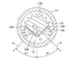
本実施の形態に係るLED光源室10は、いわゆる防爆形であり、円筒形の厚肉のガラス製シリンダ11と、このシリンダ11で密閉された空間12(図3参照)に配置されたアルミニウム製の支持体13と、この支持体13に取り付けられた複数のLED光源15,15…15とを備えて構成されている。上記ガラス製シリンダ11は、例えば外径が50mm、内径が40mm、厚さが5mmであり、透光性を有したLED光源の保護筒であって、例えば硬質ガラスで構成されている。
The LED
図2は、シリンダホルダの断面図である。
一対のシリンダホルダ8,9は、共に略同じ構造であるため、説明の便宜上、一方のシリンダホルダ9を例にとって説明する。このシリンダホルダ9は、照明装置本体1に、ねじ21を介して固定された、熱伝導性に優れる素材からなるシリンダホルダ本体22を備え、このシリンダホルダ本体22の中空部23には、電源装置6からの配線を導く配線部24を臨ませている。中空部23に連なる一方の開口部23Aは、蓋部材25を螺入して閉塞され、他方の開口部23Bには、開口中心の側から上記支持体13、上記シリンダ11及び環状のパッキン26が嵌められ、シリンダ11と開口部23Bの内壁との間に、固着剤27が填装されている。
FIG. 2 is a cross-sectional view of the cylinder holder.
Since the pair of
上記支持体13の端部は、T形ホルダ28のフランジ28Aに、ねじ29を介して固定されている。そして、このT形ホルダ28の端部に、蓋部材25の突起25Aを当接させて、シリンダホルダ本体22の一方の開口部23Aに、蓋部材25をゆっくりと螺入させていくと、上記支持体13が、一対のシリンダホルダ8,9の蓋部材25で両側から挟持され、シリンダホルダ本体22間に支持される。支持体13およびシリンダホルダ9は、熱伝導性に優れるため、放熱体となっている。
The end portion of the
上記支持体13に取り付けられた複数のLED光源15,15…15から延びた配線31は、端部にコネクタ32を有し、このコネクタ32に連結されるコネクタ33が、上記配線部24から延びた配線34に接続されている。
LED光源15,15…15のメンテナンス時には、蓋部材25を外し、コネクタ32,33の接続を外し、支持体13毎、一方向に引き出して行う。このメンテナンス作業の労務は軽減されている。
The
During the maintenance of the
上記金属製の支持体13は、図3に示すように、断面V字形状を呈しており、長さの等しい各辺には各々取り付け面13A,13Bが形成されている。各取り付け面13A,13Bには、複数のLED光源15が、支持体13の長手方向にほぼ等間隔で取り付けられている。これらLED光源15は、狭角形のLEDを主体として配列し、例えば両側および/または中央に広角形のLEDを一部配置してもよく、或いはすべて狭角形のLEDを配列してもよい。この配列に際しての狭角形LEDの数量は、広角形LEDの数量とほぼ同等数か、或いはそれ以上の数量であることが望ましい。一般に、LED光源は光量が少ないため、狭角形のLEDで指向性を高め、光源に近い箇所、例えば照明装置の真下の位置を広角形LEDで広範囲に照射することが望ましい。
As shown in FIG. 3, the
この場合、各LED光源15は、図示のように、シリンダ断面の中心Oを基準に、ほぼ放射方向に向けて光軸Pを合わせて取り付けられている。本構成では、各々の取り付け面13A,13Bのなす角度(頂角)θが、90°であり、LED光源15の照射角θ1が、45°である。なお、LED光源15は、使用の用途に応じて、例えば、片側の取り付け面13Aもしくは13Bにのみ取り付けて使用することも可能である。上記シリンダ11は、ガラス製に限定されず、例えば樹脂製でもよい。
In this case, each
上記LED光源15は、一枚の熱伝導性に優れたプレート16に取り付けられ、例えば、ねじ17で固定されている。別の形態として、一枚のプレートに複数個のLEDをモールドして形成し、このプレートを、支持体13の長手方向に並べて、各々の取り付け面13A,13Bに、例えばねじで固定してもよい。
The
支持体13の断面において残りの辺は湾曲し、この湾曲した辺には、複数の放熱フィン13Cが一体に形成されている。また、支持体13には、一対の反射体13C,13Dが配設され、この反射体13C,13Dは、表面が白色に塗装され、LED光源15からの光を反射し、この光を器具の光の照射方向に拡散させる。
The remaining side is curved in the cross section of the
図4は、別の構成を示す。この構成では、支持体13に形成された各取り付け面13A,13Bのなす角度(頂角)θが、50°であり、LED光源15の照射角θ1が、65°である。本実施の形態では、支持体13の頂角θを適宜規定することにより、LED光源15の照射角θ1を決定できる。従って、照明の配光性を考慮し、頂角θを適宜設定すれば、正確な配光を簡易に得られる。
FIG. 4 shows another configuration. In this configuration, the angle (vertical angle) θ formed by the mounting
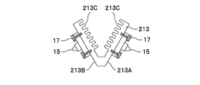
図5〜図7は、支持体の別の形態を示す。
図5の支持体113は、断面形状が略二等辺三角形状であり、等しい各辺に光源の取り付け面113A,113Bが形成され、残りの辺に放熱フィン113Cが一体に形成されている。図6の支持体213は、断面形状が略V字形状であり、等しい各辺に光源の取り付け面213A,213Bが形成され、これら辺の内側に放熱フィン213Cが各々形成されている。図7の支持体313は、図6の支持体213とほぼ同様の構造をしており、放熱フィン313Cの形状が三角歯状である点で異なっている。
いずれの支持体であっても、取り付け面に固定されたLED光源15の光軸Pを、シリンダ断面の中心Oを基準に、ほぼ放射方向に向けて一致させるように、上記シリンダの密閉空間に支持する点は共通する。
5-7 shows another form of the support.
The
Regardless of which support is used, the optical axis P of the
上記構成の防爆形照明器具では、光源にLED光源15を使用したため、蛍光ランプ等に比べ、寿命が格段に向上する。従って、メンテナンス性が向上し、特殊環境の下では、メンテナンス作業に係る労務を軽減できる。また、LED光源15がスポット光源形(狭角形)であるため、漏れ光が少なく、光のロスが低減され、配光性に優れたものが提供される。さらに、LED光源15を、シリンダ断面の中心Oを基準に、ほぼ放射方向に向けて光軸Pを合わせて取り付けているため、シリンダ11を透過する光が直進し、乱反射が減少し、光のロスが低減される。
シリンダホルダ本体22の中空部23の内側では、狭角形LED光源15,15…15から延びた配線31が、コネクタ32,33を介して、配線部24から延びた配線34に接続され、しかも、メンテナンス時には、蓋部材25を外し、コネクタ32,33の接続を外し、支持体13毎、一方向に引き出して行うことができるため、このメンテナンス作業の労務をさらに軽減できる。
In the explosion-proof lighting fixture having the above configuration, since the
Inside the
図8は、別の実施の形態を示す。
本構成では、反射板7の内側に、上記実施の形態とほぼ同様構造の2本のLED光源室10,10が平行に支持されている。この場合、照明状況に応じ、図9Aに示すように、2本のLED光源室10,10を共に照明させてもよく、図9Bに示すように、2本のLED光源室10,10の外側方向のみを照明させてもよく、図9Cに示すように、2本のLED光源室10,10の片側同一方向のみを照明させてもよい。
FIG. 8 shows another embodiment.
In this configuration, two LED
以上、一実施の形態に基づいて本発明を説明したが、本発明は、これに限定されるものではなく、種々の変更実施が可能である。例えば、上記実施の形態では、特殊環境で使用される耐圧防爆形照明装置について説明したが、安全増防爆形、或いは密閉形照明器具等であっても、本発明の適用が可能である。 While the present invention has been described based on one embodiment, the present invention is not limited to this, and various modifications can be made. For example, in the above-described embodiment, the explosion-proof illuminating device used in a special environment has been described. However, the present invention can be applied to a safety-explosion-proof illuminating device or a sealed luminaire.
8,9 シリンダホルダ
10 照明器具
11 シリンダ
13 支持体
13A,13B 取り付け面
15 LED光源
8, 9
Claims (7)
熱伝導性に優れる部材からなる一対のシリンダホルダ(8,9)と、一対のシリンダホルダ(8,9)間に保持されるシリンダ(11)と、シリンダ(11)内に配置される熱伝導性に優れる部材からなる支持体(13)とを備え、
シリンダホルダ(8,9)がシリンダホルダ本体(22)とシリンダホルダ本体(22)に螺合した蓋部材(25)とを備え、
前記支持体(13)が一対のシリンダホルダ本体(22)に螺合された蓋部材(25)で両側から狭持されてシリンダ(11)で密閉された空間内に支持され、
この支持体(13)にシリンダ断面の中心を基準にほぼ放射方向に光軸を合わせて複数のLED光源(15)を取り付けると共に、蓋部材(25)を外して複数のLED光源(15)を支持体(13)毎引き出し可能に構成した
ことを特徴とする防爆形照明装置。 Explosion-proof lighting equipment used in special environments,
A pair of cylinder holders (8, 9) made of a member having excellent thermal conductivity, a cylinder (11) held between the pair of cylinder holders (8, 9), and heat conduction disposed in the cylinder (11) And a support (13) made of a member having excellent properties,
The cylinder holder (8, 9) includes a cylinder holder body (22) and a lid member (25) screwed into the cylinder holder body (22),
The support (13) is supported in a space that is nipped from both sides by a lid member (25) screwed into a pair of cylinder holder bodies (22) and sealed by a cylinder (11) ,
The support (13) to the combined optical axis substantially radial direction relative to the center of the cylinder section mounting a plurality of LED light sources (15) Rutotomoni, a plurality of LED light sources to remove the cover member (25) (15) An explosion-proof illumination device characterized in that the support body (13) can be pulled out .
両側および/または中央に広角形LEDを配置したことを特徴とする請求項1に記載の防爆形照明装置。 The plurality of LED light sources are mainly narrow-angle LEDs,
2. The explosion-proof illumination device according to claim 1, wherein wide-angle LEDs are arranged on both sides and / or the center.
隣接する各取り付け面に前記LED光源を取り付け可能としたことを特徴とする請求項1ないし3のいずれかに記載の防爆形照明装置。 The support has a V-shaped cross section;
The explosion-proof illumination device according to any one of claims 1 to 3, wherein the LED light source can be attached to each of adjacent attachment surfaces.
Priority Applications (1)
| Application Number | Priority Date | Filing Date | Title |
|---|---|---|---|
| JP2006050108A JP4720539B2 (en) | 2006-02-27 | 2006-02-27 | Explosion-proof lighting device |
Applications Claiming Priority (1)
| Application Number | Priority Date | Filing Date | Title |
|---|---|---|---|
| JP2006050108A JP4720539B2 (en) | 2006-02-27 | 2006-02-27 | Explosion-proof lighting device |
Publications (2)
| Publication Number | Publication Date |
|---|---|
| JP2007227305A JP2007227305A (en) | 2007-09-06 |
| JP4720539B2 true JP4720539B2 (en) | 2011-07-13 |
Family
ID=38548907
Family Applications (1)
| Application Number | Title | Priority Date | Filing Date |
|---|---|---|---|
| JP2006050108A Expired - Fee Related JP4720539B2 (en) | 2006-02-27 | 2006-02-27 | Explosion-proof lighting device |
Country Status (1)
| Country | Link |
|---|---|
| JP (1) | JP4720539B2 (en) |
Families Citing this family (19)
| Publication number | Priority date | Publication date | Assignee | Title |
|---|---|---|---|---|
| JP5263658B2 (en) * | 2007-11-30 | 2013-08-14 | 東芝ライテック株式会社 | Lighting device |
| JP2009187718A (en) * | 2008-02-04 | 2009-08-20 | Hitachi Lighting Ltd | Light source device |
| JP2009277483A (en) * | 2008-05-14 | 2009-11-26 | Rohm Co Ltd | Led lamp |
| JP4465399B2 (en) * | 2008-09-16 | 2010-05-19 | シャープ株式会社 | Lighting |
| JP2010118325A (en) * | 2008-11-12 | 2010-05-27 | Tousui Ltd | Led illumination lamp |
| JP5301248B2 (en) * | 2008-11-19 | 2013-09-25 | ローム株式会社 | LED lamp |
| JP5286048B2 (en) * | 2008-11-25 | 2013-09-11 | ローム株式会社 | LED lamp |
| JP5636790B2 (en) * | 2010-07-28 | 2014-12-10 | 日亜化学工業株式会社 | Lighting device |
| JP5707565B2 (en) * | 2010-09-03 | 2015-04-30 | パナソニックIpマネジメント株式会社 | lighting equipment |
| KR101051869B1 (en) | 2010-12-14 | 2011-07-25 | 김덕용 | Led lighting module and lighting device using the module |
| JP5455951B2 (en) * | 2011-03-04 | 2014-03-26 | 日立アプライアンス株式会社 | Lamp and lighting device using the lamp |
| JP5591154B2 (en) * | 2011-03-04 | 2014-09-17 | 日立アプライアンス株式会社 | Socket with connector cover, lighting fixture and lighting device |
| DE102011017162A1 (en) * | 2011-04-15 | 2012-10-18 | Cooper Crouse-Hinds Gmbh | Explosion-proof LED module |
| JP5264964B2 (en) * | 2011-07-12 | 2013-08-14 | アジアグロースキャピタル株式会社 | Explosion-proof lighting device |
| JP5717095B2 (en) * | 2011-07-25 | 2015-05-13 | ▲高▼村電機工業株式会社 | Straight tube fluorescent lamp type LED lamp for signboard |
| JP5699067B2 (en) * | 2011-10-25 | 2015-04-08 | 北明電気工業株式会社 | Lighting device |
| JP5935575B2 (en) * | 2012-07-30 | 2016-06-15 | 岩崎電気株式会社 | Hanging explosion-proof lighting system |
| JP5686909B2 (en) * | 2014-01-07 | 2015-03-18 | 日立アプライアンス株式会社 | Lamp and lighting device using the lamp |
| FI127773B (en) * | 2016-04-08 | 2019-02-15 | Atexor Oy | Sealing Arrangement for an Electronic Device |
Citations (8)
| Publication number | Priority date | Publication date | Assignee | Title |
|---|---|---|---|---|
| JPS5748512U (en) * | 1980-09-01 | 1982-03-18 | ||
| JPH1153929A (en) * | 1997-07-30 | 1999-02-26 | Iwasaki Electric Co Ltd | Explosion-proof type luminaire |
| JP2002008414A (en) * | 2000-06-26 | 2002-01-11 | Toshiba Lighting & Technology Corp | Lamp for marker light and aircraft warning light |
| JP2003124520A (en) * | 2001-10-17 | 2003-04-25 | Nippon Computer Network Kk | Photopolymerization radiation device |
| JP2004030929A (en) * | 2002-06-21 | 2004-01-29 | Toshiba Lighting & Technology Corp | Led device and led lighting device |
| JP2004134249A (en) * | 2002-10-10 | 2004-04-30 | Mitsubishi Electric Corp | Lighting device |
| JP2004207109A (en) * | 2002-12-26 | 2004-07-22 | Nikkeikin Aluminium Core Technology Co Ltd | Independent power source type lighting post |
| JP2005135921A (en) * | 2004-11-25 | 2005-05-26 | Toshiba Lighting & Technology Corp | Fluorescent lamp and illumination fixture |
-
2006
- 2006-02-27 JP JP2006050108A patent/JP4720539B2/en not_active Expired - Fee Related
Patent Citations (8)
| Publication number | Priority date | Publication date | Assignee | Title |
|---|---|---|---|---|
| JPS5748512U (en) * | 1980-09-01 | 1982-03-18 | ||
| JPH1153929A (en) * | 1997-07-30 | 1999-02-26 | Iwasaki Electric Co Ltd | Explosion-proof type luminaire |
| JP2002008414A (en) * | 2000-06-26 | 2002-01-11 | Toshiba Lighting & Technology Corp | Lamp for marker light and aircraft warning light |
| JP2003124520A (en) * | 2001-10-17 | 2003-04-25 | Nippon Computer Network Kk | Photopolymerization radiation device |
| JP2004030929A (en) * | 2002-06-21 | 2004-01-29 | Toshiba Lighting & Technology Corp | Led device and led lighting device |
| JP2004134249A (en) * | 2002-10-10 | 2004-04-30 | Mitsubishi Electric Corp | Lighting device |
| JP2004207109A (en) * | 2002-12-26 | 2004-07-22 | Nikkeikin Aluminium Core Technology Co Ltd | Independent power source type lighting post |
| JP2005135921A (en) * | 2004-11-25 | 2005-05-26 | Toshiba Lighting & Technology Corp | Fluorescent lamp and illumination fixture |
Also Published As
| Publication number | Publication date |
|---|---|
| JP2007227305A (en) | 2007-09-06 |
Similar Documents
| Publication | Publication Date | Title |
|---|---|---|
| JP4720539B2 (en) | Explosion-proof lighting device | |
| JP5702784B2 (en) | Daylight lighting apparatus and method with auxiliary lighting fixture | |
| US8002446B1 (en) | Virtual direct and indirect suspended lighting fixture | |
| JP2009266780A (en) | Luminous body and luminaire | |
| JP2008171685A (en) | Lighting fixture | |
| JP2015164098A (en) | Lens and lighting device including the same | |
| JP2010009969A (en) | Lighting device | |
| JP5570465B2 (en) | Lighting device | |
| JP2011076979A (en) | Mounting auxiliary member, and lighting system | |
| CN104160205A (en) | Lighting device | |
| JP2010067410A (en) | Lighting fixture | |
| KR200466429Y1 (en) | Reflector for fluorescent lamp unit | |
| JP5139929B2 (en) | lighting equipment | |
| JP7112018B2 (en) | Covers for luminaires, luminaires and luminaires | |
| JP6460805B2 (en) | lighting equipment | |
| JP2014116270A (en) | Lighting fixture | |
| JP6281322B2 (en) | Explosion-proof lighting equipment | |
| FI77107C (en) | Light fixture for compact fluorescent lamp | |
| CN218672006U (en) | Angle-adjustable spotlight | |
| JP6558689B2 (en) | lighting equipment | |
| TWM446277U (en) | Illumination device | |
| JP7378205B2 (en) | Lighting devices and couplings for lighting devices | |
| JP2010067411A (en) | Luminaire | |
| JP2022025919A (en) | Lighting device | |
| JP6281321B2 (en) | Explosion-proof lighting equipment |
Legal Events
| Date | Code | Title | Description |
|---|---|---|---|
| A621 | Written request for application examination |
Free format text: JAPANESE INTERMEDIATE CODE: A621 Effective date: 20090123 |
|
| A977 | Report on retrieval |
Free format text: JAPANESE INTERMEDIATE CODE: A971007 Effective date: 20100723 |
|
| A131 | Notification of reasons for refusal |
Free format text: JAPANESE INTERMEDIATE CODE: A131 Effective date: 20100810 |
|
| A521 | Request for written amendment filed |
Free format text: JAPANESE INTERMEDIATE CODE: A523 Effective date: 20101008 |
|
| RD02 | Notification of acceptance of power of attorney |
Free format text: JAPANESE INTERMEDIATE CODE: A7422 Effective date: 20101008 |
|
| TRDD | Decision of grant or rejection written | ||
| A01 | Written decision to grant a patent or to grant a registration (utility model) |
Free format text: JAPANESE INTERMEDIATE CODE: A01 Effective date: 20110308 |
|
| A61 | First payment of annual fees (during grant procedure) |
Free format text: JAPANESE INTERMEDIATE CODE: A61 Effective date: 20110321 |
|
| FPAY | Renewal fee payment (event date is renewal date of database) |
Free format text: PAYMENT UNTIL: 20140415 Year of fee payment: 3 |
|
| R150 | Certificate of patent or registration of utility model |
Ref document number: 4720539 Country of ref document: JP Free format text: JAPANESE INTERMEDIATE CODE: R150 |
|
| S531 | Written request for registration of change of domicile |
Free format text: JAPANESE INTERMEDIATE CODE: R313531 |
|
| R350 | Written notification of registration of transfer |
Free format text: JAPANESE INTERMEDIATE CODE: R350 |
|
| LAPS | Cancellation because of no payment of annual fees |