JP4718540B2 - Metal vent - Google Patents
Metal vent Download PDFInfo
- Publication number
- JP4718540B2 JP4718540B2 JP2007508452A JP2007508452A JP4718540B2 JP 4718540 B2 JP4718540 B2 JP 4718540B2 JP 2007508452 A JP2007508452 A JP 2007508452A JP 2007508452 A JP2007508452 A JP 2007508452A JP 4718540 B2 JP4718540 B2 JP 4718540B2
- Authority
- JP
- Japan
- Prior art keywords
- membrane
- vent
- metal
- opening
- porous
- Prior art date
- Legal status (The legal status is an assumption and is not a legal conclusion. Google has not performed a legal analysis and makes no representation as to the accuracy of the status listed.)
- Expired - Fee Related
Links
Images


Classifications
-
- F—MECHANICAL ENGINEERING; LIGHTING; HEATING; WEAPONS; BLASTING
- F16—ENGINEERING ELEMENTS AND UNITS; GENERAL MEASURES FOR PRODUCING AND MAINTAINING EFFECTIVE FUNCTIONING OF MACHINES OR INSTALLATIONS; THERMAL INSULATION IN GENERAL
- F16K—VALVES; TAPS; COCKS; ACTUATING-FLOATS; DEVICES FOR VENTING OR AERATING
- F16K24/00—Devices, e.g. valves, for venting or aerating enclosures
- F16K24/04—Devices, e.g. valves, for venting or aerating enclosures for venting only
-
- G—PHYSICS
- G03—PHOTOGRAPHY; CINEMATOGRAPHY; ANALOGOUS TECHNIQUES USING WAVES OTHER THAN OPTICAL WAVES; ELECTROGRAPHY; HOLOGRAPHY
- G03B—APPARATUS OR ARRANGEMENTS FOR TAKING PHOTOGRAPHS OR FOR PROJECTING OR VIEWING THEM; APPARATUS OR ARRANGEMENTS EMPLOYING ANALOGOUS TECHNIQUES USING WAVES OTHER THAN OPTICAL WAVES; ACCESSORIES THEREFOR
- G03B17/00—Details of cameras or camera bodies; Accessories therefor
- G03B17/02—Bodies
-
- H—ELECTRICITY
- H05—ELECTRIC TECHNIQUES NOT OTHERWISE PROVIDED FOR
- H05K—PRINTED CIRCUITS; CASINGS OR CONSTRUCTIONAL DETAILS OF ELECTRIC APPARATUS; MANUFACTURE OF ASSEMBLAGES OF ELECTRICAL COMPONENTS
- H05K5/00—Casings, cabinets or drawers for electric apparatus
- H05K5/02—Details
- H05K5/0213—Venting apertures; Constructional details thereof
- H05K5/0216—Venting plugs comprising semi-permeable membranes
Landscapes
- Engineering & Computer Science (AREA)
- General Engineering & Computer Science (AREA)
- Mechanical Engineering (AREA)
- Physics & Mathematics (AREA)
- General Physics & Mathematics (AREA)
- Microelectronics & Electronic Packaging (AREA)
- Separation Using Semi-Permeable Membranes (AREA)
- Self-Closing Valves And Venting Or Aerating Valves (AREA)
- Control And Other Processes For Unpacking Of Materials (AREA)
- Closures For Containers (AREA)
Abstract
Description
通気口は多くの用途で使用されている。例えば、自動車産業では、電気部品のハウジング、歯車のハウジング、ブレーキのハウジング及び車体さえも、ハウジング又は車体内と周囲環境それぞれの圧力を等しくするため通気口を使用している。他の用途における通気口の機能は、圧力を等しくするためのバルク流動(bulk flow)のみならず、湿気を制御するため媒体を通過させる水分の拡散などの選択された成分に媒体を通過させて輸送するための拡散である。これらタイプの用途では、駆動力は、圧力ではなく、温度、浸透圧、静電気の引力もしくは斥力などの駆動力である。通気口は、他の多くの用途、例えば、電気設備や機械設備のハウジング及び化学薬品の容器にも使用される。このようなハウジング、封入体又は容器を、本願では、総合的に「ハウジング」と呼ぶ。 Vents are used in many applications. For example, in the automotive industry, electrical component housings, gear housings, brake housings and even car bodies use vents to equalize the pressure in the housing or car body and the surrounding environment. The function of the vent in other applications is to allow the media to pass through selected components such as bulk flow to equalize pressure as well as diffusion of moisture through the media to control moisture. Diffusion for transport. In these types of applications, the driving force is not pressure but driving force such as temperature, osmotic pressure, electrostatic attraction or repulsion. Vents are also used in many other applications, such as electrical and mechanical housings and chemical containers. Such a housing, enclosure or container is generally referred to herein as a “housing”.
多くの用途で、通気口は、圧力を等しくするため気体透過性でなければならないだけでなく、ハウジングの内部を、中の設備又は部品を損傷したりハウジングを腐食する湿気、液体又は汚染物に対して密封するため液体不透過性でなければならない。 In many applications, vents must not only be gas permeable to equalize pressure, but also the interior of the housing to moisture, liquids or contaminants that can damage equipment or components inside or corrode the housing. It must be liquid impermeable to seal against.
ポリテトラフルオロエチレン(PTFE)、ポリプロピレン又はポリエチレンで製造されたポリマー又はプラスチック製成形本体と多孔質膜からなるプレス嵌め通気口が知られている。既知のポリマー製通気口は、例えば、呼吸弁、フィルター、ダイアフラム装置などの空気抜き装置として使用されている。プレス嵌め通気口は、一般に、円周部分に通孔を配置された膜を備え、その通孔は、その通孔を通じて連結された硬質樹脂部分の間に配置されている。この硬質部材は、このプレス嵌め製品を形成する軟質樹脂で取り囲まれている。ポリマー又はプラスチックで成形された通気口の他の多くの配置構成は知られているが、すべて重大な欠点をかかえている。 There is known a press-fit vent made of a polymer or plastic molded body made of polytetrafluoroethylene (PTFE), polypropylene or polyethylene and a porous membrane. Known polymer vents are used, for example, as venting devices such as breathing valves, filters, diaphragm devices and the like. The press-fit vent generally includes a film having through holes arranged in the circumferential portion, and the through holes are arranged between the hard resin portions connected through the through holes. The hard member is surrounded by a soft resin that forms the press-fit product. Many other arrangements of vents made of polymer or plastic are known, but all have significant drawbacks.
ポリマー及びプラスチック製の通気口は、耐熱性と耐薬品性のみならず耐久性が不足している。したがって、これらの通気口は、高温、紫外線(「UV」)又は化学的な分解もしくは衝撃を受けることがある特定の用途では、使用できない。 Polymer and plastic vents lack durability as well as heat and chemical resistance. Thus, these vents cannot be used in certain applications that may be subject to high temperatures, ultraviolet ("UV") or chemical degradation or impact.
金属製通気口は、いくつかの用途では耐久性が改善されることは知られている。しかし、既知の金属製通気口は、ある種の形状のシーラント、接着剤又はガスケットを頼りにして膜を通気口に対してシールしている。これらのシーラントとガスケットも、高温では分解されるので役に立たない。 Metal vents are known to improve durability in some applications. However, known metal vents rely on some form of sealant, adhesive or gasket to seal the membrane against the vent. These sealants and gaskets are also useless because they decompose at high temperatures.
したがって、高温と腐食性環境を含む有害な条件に耐えることができる耐久性のある金属製通気口が要望されている。 Accordingly, there is a need for a durable metal vent that can withstand harmful conditions including high temperatures and corrosive environments.
一側面で、本発明は、流体が通過する開口、その開口を囲む第一膜保持表面及びその開口を囲む第二膜保持面を含む金属製本体、並びに前記第一膜保持面と接触する第一面と前記第二膜保持面と接触する第二面を有する膜から本質的になる通気口であって、前記膜、前記第一膜保持面及び第二膜保持面の間の相互関係によって、前記開口を囲むシールが形成される通気口を提供する。 In one aspect, the present invention provides a metal body including an opening through which a fluid passes, a first film holding surface surrounding the opening and a second film holding surface surrounding the opening, and a first body in contact with the first film holding surface. A vent consisting essentially of a membrane having a second surface in contact with one surface and the second membrane holding surface, depending on the interrelationship between the membrane, the first membrane holding surface and the second membrane holding surface Providing a vent formed with a seal surrounding the opening.
別の側面で、本発明は、流体が通過する開口及びその開口を囲む膜保持表面を有する金属製本体;前記開口を覆いかつ前記第一膜保持表面と接触する第一面及びその第一面と反対側の第二面を有する膜;前記膜の第二面と接触する第二膜保持表面を有し、締まり嵌めによって本体に取り付けられて前記開口を囲むシールを形成する金属製シェルから本質的になる通気口を提供する。 In another aspect, the present invention provides a metal body having an opening through which a fluid passes and a membrane holding surface surrounding the opening; a first surface covering the opening and in contact with the first membrane holding surface, and the first surface A membrane having a second surface opposite to the membrane; essentially from a metal shell having a second membrane holding surface in contact with the second surface of the membrane and attached to the body by an interference fit to form a seal surrounding the opening Providing a vent that will
別の側面で、本発明は、ハウジング;ハウジングのポート;及びそのポートの上に配置された通気口を含む装置であって、該通気口が、気体が通過する開口を有する金属製本体;その開口を跨ぐ膜;並びに気体が通過する穿孔を有しかつ締まり嵌めで前記本体に取り付けられて前記膜と本体の間にシールを形成し、そのシールが前記開口を囲んでいる金属性シェルから本質的になる、そのような装置を提供する。 In another aspect, the present invention provides a device comprising a housing; a port of the housing; and a vent disposed over the port, wherein the vent has an opening through which gas passes; A membrane over the opening; and a perforation through which gas passes and is attached to the body with an interference fit to form a seal between the membrane and the body, the seal being essentially from a metallic shell surrounding the opening Such an apparatus is provided.
さらに別の側面で、本発明は、気体が通過する開口を有する金属製ハウジングを提供し、膜がハウジングに接触するようにその膜で前記開口を覆い、穿孔を中に有するカバーを、そのカバーが前記膜に接触するように締まり嵌めでハウジングに取り付けるステップを含んでなり、その結果シールが前記膜とハウジングの間に形成される通気口の製造方法を提供する。 In yet another aspect, the present invention provides a metal housing having an opening through which a gas passes, covering the opening with the membrane so that the membrane contacts the housing, and a cover having perforations therein. Providing a method of manufacturing a vent wherein a seal is formed between the membrane and the housing.
本発明の一側面による通気口は、機械設備もしくは電気設備用の設備封入容器又は化学薬剤封入容器などのハウジングの圧力を等しくする。一側面で、本発明の通気口は、金属製のシェル又はキャップ付きのすべて金属製の本体で構成されている。本発明の通気口本体は、前記封入容器と大気の間を流体で連通させる開口を有している。蒸気透過性でかつ液体不透過性の膜が、前記開口を跨いで封入容器と大気の間を気体で流通させるが、液体又は汚染物の進入を防止する。金属製シェルは、膜を保護しそして大気と膜の間を流体で連通させる穿孔を有するように適応させることができる。 The vent according to one aspect of the present invention equalizes the pressure in a housing, such as a facility enclosure or a chemical agent enclosure for mechanical or electrical installations. In one aspect, the vent of the present invention comprises an all-metal body with a metal shell or cap. The vent body of the present invention has an opening that allows fluid communication between the enclosure and the atmosphere. A vapor-permeable and liquid-impermeable membrane allows gas to flow between the enclosure and the atmosphere across the opening, but prevents liquid or contaminants from entering. The metal shell can be adapted to have perforations that protect the membrane and provide fluid communication between the atmosphere and the membrane.
前記シェルと通気口本体は、締り嵌めだけを使う独特な方法で組み立てられる。その膜は、前記シェル上の上部膜保持表面と通気口本体上の下部膜保持表面との間で押圧される。膜が押圧されると膜が開口を覆ってシールする。この新規な構造によって、時間の経過とともに及び厳しい環境にさらされたときに分解することがあるシーラント、接着剤又はガスケットを使用しないですむ極めて堅牢で耐久性のある通気口が提供される。 The shell and vent body are assembled in a unique way using only an interference fit. The membrane is pressed between the upper membrane holding surface on the shell and the lower membrane holding surface on the vent body. When the membrane is pressed, the membrane covers and seals the opening. This novel structure provides an extremely robust and durable vent that eliminates the use of sealants, adhesives or gaskets that can degrade over time and when exposed to harsh environments.
また、本発明の通気口は、金属製なので照明装置の封入容器などの高温の用途で有利に使用できる。照明設備特にUnderwriters Laboratories(「UL」)が列挙している非常時用照明設備には有利である。プラスチックなどで成形された非金属製通気口は、一般に、防火照明のUL標準を満たすことができない。さらに、金属製であることは、プラスチックの射出成形及び押出し成形がコスト高でかつ複雑であるので、ポリマー製であることより、限られた商業生産にとって経費効率が高い。 In addition, since the vent of the present invention is made of metal, it can be advantageously used in high-temperature applications such as an enclosure for lighting devices. It is advantageous for lighting installations, especially emergency lighting installations listed by Underwriters Laboratories ("UL"). Non-metallic vents molded of plastic or the like generally cannot meet the UL standard for fire protection lighting. Furthermore, being made of metal is more cost effective for limited commercial production than being made of polymer, because plastic injection and extrusion are costly and complex.
通気口本体
一側面で、金属製通気口本体は、ハウジング中に挿入する長い基部及び膜を保持する広がった頭部を備えている。開口が、通気口本体を貫通して基部から頭部まで延びて、ハウジングと大気の間を流体で連通させる。
On one side of the vent body, the metal vent body has a long base for insertion into the housing and a widened head that holds the membrane. An opening extends from the base to the head through the vent body and provides fluid communication between the housing and the atmosphere.
通気口本体の基部は、どんな形状でもよいが、一般に、ハウジング中にドリルであけるか又は形成される通気孔に整合するように円筒形である。その基部は、通気口を挿入しやすくしたり又は通気口をハウジング中に押し込めるように、その末端にテーパーが付いていてもよい。あるいは、ハウジングのタップ立てされた通孔と協働するねじを基部の外側に切ってもよい。各種の他の固定機構を、通気口を保持するため基部に設けてもよい。例えば、通気口を保持するため、スナップリングを受け入れる溝を基部に設けてもよい。あるいは、ロックリングを、ハウジングに挿入した後、基部に押し付けてもよい。基部は、ハウジングのタップ立てされた通孔に整合するようにねじをきることが好ましい。 The base of the vent body may be of any shape, but is generally cylindrical so that it matches the vent that is drilled or formed in the housing. The base may be tapered at the end to facilitate insertion of the vent or to force the vent into the housing. Alternatively, a screw that cooperates with the tapped through hole in the housing may be cut outside the base. Various other securing mechanisms may be provided at the base to hold the vent. For example, a groove for receiving a snap ring may be provided in the base to hold the vent. Alternatively, the lock ring may be pressed against the base after being inserted into the housing. The base is preferably threaded to align with the tapped through hole in the housing.
通気口本体の頭部は、下部の膜保持表面を有している。この膜保持表面は、円筒形開口に整合するように一般に円形であるが、用途に適したどんな形状と大きさでもよい。膜保持表面は開口を囲むことが好ましい。通気口本体の頭部の形状は決定的なものではなく、用途によっては、円筒形でも又は他の形状でもよい。例えば、頭部は、レンチを使って、ねじを切った通気口をタップ立てしたハウジング中にねじ込むことができるように六角形の部分を有していてもよい。 The head of the vent body has a lower membrane holding surface. The membrane holding surface is generally circular to match the cylindrical opening, but can be any shape and size suitable for the application. The membrane holding surface preferably surrounds the opening. The shape of the head of the vent main body is not critical, and may be cylindrical or other shapes depending on the application. For example, the head may have a hexagonal portion so that it can be screwed into a tapped housing using a wrench with a threaded vent.
開口は、通気口本体中に機械加工で又は成形でつくることができ、まっすぐ、テーパー付きなどの構造でもよい。例えば、開口は、基部の直径が小さく、頂部のほうに向かうにつれて直径が徐々に増大するテーパー付き通孔でもよい。あるいは、その通孔の直径が逐次増大して、シャフトの直径が一般に頂部より小さくてもよい。頭部に近いより大きい領域には、より大きい膜を使うことができ、その結果、いくつかの用途で通気を改善できる。 The openings can be machined or molded into the vent body and can be straight, tapered or the like. For example, the opening may be a tapered through hole having a small diameter at the base and a gradually increasing diameter toward the top. Alternatively, the diameter of the through-holes may increase sequentially so that the shaft diameter is generally smaller than the top. Larger membranes near the head can use larger membranes, which can improve ventilation in some applications.
シェル
シェルは、全体が金属製であり、通気口本体に締まり嵌めで固定するように構成されている。一側面で、シェルは、類似の形状の通気口本体の頭部に整合するように円筒形である。好ましくは、シェルは、物理的損傷や液体への暴露に対して膜を保護するように構成されておりかつ気体を通過させるため穴が設けられている。
The shell is entirely made of metal, and is configured to be fixed to the vent hole body with an interference fit. In one aspect, the shell is cylindrical to match the head of a similarly shaped vent body. Preferably, the shell is configured to protect the membrane against physical damage and liquid exposure and is provided with a hole for the passage of gas.
シェルは、上部膜保持表面を備えている。その上部膜保持表面は、通気口本体の下部膜保持表面と協働して膜を押圧している。膜が押圧されると、開口がシールされて液体や汚染物の侵入が防止される。 The shell has an upper membrane holding surface. The upper membrane holding surface presses the membrane in cooperation with the lower membrane holding surface of the vent body. When the membrane is pressed, the opening is sealed to prevent entry of liquid or contaminants.
前記上部及び下部の膜保持表面は、好ましくは、膜の押圧を最大にするように構成されている。押圧を改善するため、これら保持表面は、接触面積を最小にするように配置構成されている。例えば、隆条などの突出部を、シェル又は通気口本体の膜保持表面に設けて、膜の接触面積を最小にして、単位面積当たりの押圧力を増大させる。 The upper and lower film holding surfaces are preferably configured to maximize the pressing of the film. In order to improve the pressing, these holding surfaces are arranged to minimize the contact area. For example, protrusions such as ridges are provided on the membrane holding surface of the shell or vent body to minimize the contact area of the membrane and increase the pressing force per unit area.
通気口本体及びシェルの金属材料の選択は決定的なことではないので、当業者には、材料の選択が用途によって変わることは分かるであろう。通気口は、ステンレス鋼で製造することが好ましい。例えば、そのステンレス鋼は、ニッケル、クロム、バナジウム、モリブデン又はマグネシウム及びその組み合わせを含有する合金である。 Since the choice of metal material for the vent body and shell is not critical, those skilled in the art will appreciate that the choice of material will vary depending on the application. The vent is preferably made of stainless steel. For example, the stainless steel is an alloy containing nickel, chromium, vanadium, molybdenum or magnesium and combinations thereof.
膜
膜は多孔質である。膜は延伸ポリテトラフルオロエチレン(ePTFE)で製造することが好ましい。典型的なePTFE材料は、米国特許第3,953,566号、同第3,962,153号、同第4,096,227号、同第4,187,390号、同第4,902,423号又は同第4,478,665号に記載の方法によって製造できる。なお、これら特許文献は本願に援用するものである。また、多孔質ePTFEの膜は、他の方法でも製造できる。多孔質ePTFEは、ポリメリックノードと連続フィブリルの多孔質ネットワークで構成され、米国デラウェア州ニューアーク所在のW.L.Gore & Associates,Inc.から多種類の形態で市販されている。
Film membrane is porous. The membrane is preferably made of expanded polytetrafluoroethylene (ePTFE). Typical ePTFE materials can be produced by the methods described in U.S. Pat. Nos. 3,953,566, 3,962,153, 4,096,227, 4,187,390, 4,902,423, or 4,478,665. In addition, these patent documents are used for this application. The porous ePTFE membrane can also be produced by other methods. Porous ePTFE is composed of a porous network of polymeric nodes and continuous fibrils, and is commercially available in many forms from WL Gore & Associates, Inc., Newark, Delaware.
用語「ePTFE」は、本願で使用する場合、ノードとフィブリルの構造を有するPTFE材料を含むものとし、ポリマー材料の比較的大きなノードから延びるフィブリルを有するわずかに延伸された構造から、単にノードの点で互いに交差するフィブリルを有する極端に延伸された構造までの範囲のものが含まれている。その構造のフィブリルの特徴は顕微鏡で確認される。ノードはいくつかの構造については容易に確認できるが、多くの極端に延伸された構造は、専ら、フィブリル及びフィブリルの交差点としてのみ現れるノードからなっている。生成するミクロ細孔又は気孔は、気体又は空気を良好に流動させながら耐水性を付与する。 The term “ePTFE” as used in this application is intended to include PTFE material having a node and fibril structure, from a slightly stretched structure having fibrils extending from a relatively large node of polymer material, simply in terms of nodes. Those ranging from extremely stretched structures with fibrils intersecting each other are included. The characteristics of the fibrils in the structure are confirmed with a microscope. Although nodes can be easily identified for some structures, many extremely stretched structures consist exclusively of nodes that appear only as fibrils and fibril intersections. The generated micropores or pores provide water resistance while allowing gas or air to flow well.
膜は、添加物とも呼称される充填剤又はコーティングを一種以上、随意選択的に含有していてもよい。例えば、カバーがePTFEの膜である場合、添加物は、ePTFE自体のマトリックス中に含有させてもよい。あるいは、膜には、添加物を薄膜の細孔中に良好に侵入させる添加物/溶媒混合物を吸収させてもよい。この吸収は、第一に添加物/溶媒の溶液を調製し第二にその溶液を延伸PTFEのような多孔質薄膜と混合することによって行われる。添加物は、膜の片面又は両面にコートしてもよい。望ましい添加物としては、吸収剤、吸着剤、表面エネルギー調節剤、着色剤、顔料、抗微生物薬、抗菌薬、抗真菌薬及びその混合物がある。 The membrane may optionally contain one or more fillers or coatings, also called additives. For example, if the cover is an ePTFE membrane, the additive may be included in the matrix of ePTFE itself. Alternatively, the membrane may absorb an additive / solvent mixture that allows the additive to penetrate well into the pores of the thin film. This absorption is performed by first preparing an additive / solvent solution and secondly mixing the solution with a porous membrane such as expanded PTFE. Additives may be coated on one or both sides of the membrane. Desirable additives include absorbents, adsorbents, surface energy modifiers, colorants, pigments, antimicrobial agents, antibacterial agents, antifungal agents and mixtures thereof.
膜は、織物、不織布又はファイバースクリムなどの支持層を、随意選択的に含んでいてもよい。その支持層は、積層する、接着する又は単に膜の近くに配置するだけでもよい。 The membrane may optionally include a support layer such as a woven, non-woven or fiber scrim. The support layer may be laminated, glued or simply placed near the membrane.
膜の厚さは、決定的なものではないが、膜は、シェルと通気口本体の締り嵌めによってシールを維持するのに十分な厚さでなくてはならない。薄い膜は、部分のより正確な機械加工と仕上げが必要である。より厚い膜でも、効果的に通気するように十分透過性であれば、使用できる。好ましくは、膜の厚さは、少なくとも約3ミル又は少なくとも約5ミル、10ミル又は13ミルである。 The thickness of the membrane is not critical, but the membrane must be thick enough to maintain a seal with an interference fit between the shell and the vent body. Thin films require more precise machining and finishing of parts. Even thicker membranes can be used if they are sufficiently permeable to effectively vent. Preferably, the film thickness is at least about 3 mils or at least about 5 mils, 10 mils or 13 mils.
シェルは、好ましくは締り嵌めで通気口本体に固定される。用語「締り嵌め」は、本願で使用する場合、接着剤などの接合剤、溶接、ろう付けなど又はコーキング材料、圧縮ガスケット、ばねなどを使うことなく、アセンブリが、部品内の内力と部品間の摩擦を総合することによって維持される嵌合部品のすべての方式を含むものとする。 The shell is preferably secured to the vent body with an interference fit. The term “interference fit” as used in this application refers to an assembly where the internal force between the parts and the part is not used without the use of a bonding agent such as an adhesive, welding, brazing, or caulking materials, compression gaskets, springs, etc. It shall include all methods of mating parts that are maintained by integrating friction.
シェルを、締り嵌めで通気口本体に固定する方法には、例えば、スナップリング、プレス嵌め、摩擦嵌めなどを使用することが含まれている。一側面で、シェルは、通気口本体の溝又は凹部にはまるように内側に突出するタブを備えている。そのタブは凹部の定位置にパチンと嵌ってシェルを定位置にロックする。 Methods for securing the shell to the vent body with an interference fit include, for example, using a snap ring, press fit, friction fit, and the like. In one aspect, the shell includes a tab that projects inward to fit into a groove or recess in the vent body. The tab snaps into place in the recess to lock the shell in place.
別の側面で、本発明は、一体式の金属製通気口本体を提供する。この側面では、開口がその一体式の通気口本体を基部から頭部まで貫通して設けられる。その頭部は、前記開口を囲む下部膜保持表面を有している。その頭部は、前記開口を囲む上部膜保持表面も有している。膜が、上部膜保持表面と下部膜保持表面の間に配置され、これら膜保持表面の間で押圧によって定位置に保持されている。例えば、その膜は、膜保持表面間に配置されて、その上部膜保持表面は、膜が上部膜保持表面と下部膜保持表面の間に保持されるように、圧延又は押圧されて通気口本体を変形させたリップ又は端縁の部分であってもよい。 In another aspect, the present invention provides an integral metal vent body. In this aspect, an opening is provided through the integral vent body from the base to the head. The head has a lower membrane holding surface surrounding the opening. The head also has an upper membrane holding surface surrounding the opening. A membrane is disposed between the upper membrane holding surface and the lower membrane holding surface and is held in place by pressing between these membrane holding surfaces. For example, the membrane is disposed between the membrane holding surfaces, and the upper membrane holding surface is rolled or pressed so that the membrane is held between the upper membrane holding surface and the lower membrane holding surface. It may be a lip or edge portion that is deformed.
本発明の通気口は、一旦組み立てられたならば、既知の手段でハウジング内に取り付けられ次いでシールされる。かような手段としては、例えば、フレアリング、かしめ、シャフトのねじに対するシーラントのコーティング又はシャフトに嵌めるOリングがある。Oリングは、使用される場合、通気口本体の下部表面とハウジングの間で圧縮される。 The vent of the present invention, once assembled, is installed in a housing by known means and then sealed. Such means include, for example, flaring, caulking, coating of sealant against shaft threads, or O-rings that fit into the shaft. When used, the O-ring is compressed between the lower surface of the vent body and the housing.
本発明の通気口は、同じ番号が同じ部品を表す添付図面を参照することによって最もよく理解できる。 The vents of the present invention can best be understood by referring to the accompanying drawings in which like numerals represent like parts.
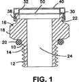
本発明の一側面を図1-3に示す。通気口本体10は、ねじ14を有する基部12及び六角形の部分18を有する頭部16を備えている。その六角形部分は、レンチを使って、通気口を、タップ立てされたハウジング中にねじ込むことができる。ねじは、National Pipe Thread(NPT)又は平行ねじでよい。平行ねじを使う場合は、ガスケット20を使って、通気口をハウジングに対してシールできる。溝22が、頭部の六角形部分の上部に切り出されている。開口24が、基部から頭部まで通気口を貫通して延びている。
One aspect of the present invention is shown in FIG. 1-3. The
シェル30が、締り嵌めによって通気口本体に固定されている。シェルの上のスナップリング38が溝22と協働してシェルを通気口本体に固定している。シェルは、キャップのほうに延びるじゃま板32も備えている。
A
キャップ40は、シェル30の上に嵌り、シェルに当たっているディンプル42と協働して定位置に保持されている。そのキャップは、その外周部に穿孔44を有している。その穿孔はじゃま板32の外側に配置されていて、穿孔に入る液体はじゃま板によって膜50に接触しないようになっている。ディンプル間の間隙が、キャップとシェルの間にA-Aで示す、穿孔44に入いる液体の廃液路を提供している。トップシェルのディンプル46は、じゃま板の上部端縁に接触し、気体が流動できるようにトップシェルとじゃま板の間に間隙を維持している。
The
膜50は、シェルの上部膜保持表面48と通気口本体の下部膜保持表面34の間でその周縁部が押圧される。
The periphery of the
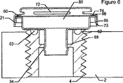
図4-6は別の実施態様を示す。通気すべきハウジングは壁2を有し、その壁は、ねじ62を有する挿入体60を受け入れる開口又はポート4を有する壁2を備えている。その挿入体60は、六角形の凹部64を有し、その凹部は、この挿入体をハウジングに装着するためのアレンレンチ型ドライバーを受け入れるように構成された六角形の凹部64を有している。流体が通過する流路66が、前記挿入体内に形成されているか又は機械加工されている。ウエブ68が、前記流路の内側から延びている。その流路を囲んでガッスケット63を受け入れる溝61がある。
Figures 4-6 show another embodiment. The housing to be vented has a
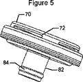
通気口はシェル70と通気口本体80を含んでいる。その通気口本体の中には、隆起したスナップリング84を有する長い基部82が形成されている。シェルには、気体をトップシェルを通って流動させる穿孔72が含まれている。
The vent includes a shell 70 and a
そのシェルは、通気口本体の上に嵌め込まれ、締り嵌めで保持されている。シェルの外周部分に形成された、内側に突出しているスナップリング73は、通気口本体の外側底部端縁86と協働してこれら二つの部品を保持している。膜50は、その外周部分を、シェルの上部膜保持表面74と通気口本体の下部膜保持表面88の間で押圧されている。
The shell is fitted over the vent body and held with an interference fit. An inwardly projecting
前記基部は前記挿入体中に圧入され、そしてそのスナップリングは前記流路内のウエブと協働して通気口を保持する。ガスケットは、壁と通気口本体の間で押圧されて通気口と挿入体の間のシールを形成する。 The base is press fit into the insert and the snap ring cooperates with the web in the flow path to hold the vent. The gasket is pressed between the wall and the vent body to form a seal between the vent and the insert.
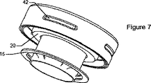
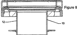
他の実施態様を図7-10に示す。図7-8において、通気口本体10は、ハウジング中に挿入する円筒形基部12を有している。ハウジング中に挿入された後、基部に対して押圧されたロックリング15は、通気口を定位置に保持する。ガスケット20は、通気口をハウジングに対してシールする。図9は二部品構造体を示す。トップシェルは、開口を有する通気口本体の上に押圧されて膜を開口に対してシールしている。図10は一部品の通気口本体の構造を示す。この金属製通気口本体は、上部膜保持表面と下部膜保持表面の両方を有している。
Another embodiment is shown in FIGS. 7-10. 7-8, the
試験方法
耐水性‐スーター法(Suter method)
本発明に使用するのに適した膜は、低い水のエントリ圧(low water entry pressure)を加える改良スーター法の装置を使って、耐水性を試験できる。漏れ止め圧着装置の二つの円形ゴム製ガスケトによって、試料の下面に対して水圧がかかっている。変形可能な試料は、その上に補強スクリム(例えば、目の粗い不織布)が圧着されている。試料の上面は、大気に対して開放されているのでオペレーターは目視できる。試料の裏面に対する水圧は、水タンクに接続されたポンプによって2psiまで上昇させるが、この圧力は圧力計で表示されるので直列のバルブで調節される。耐水性が不足している場合に試料を通過して押し出される水が現れるかどうか、3分間、試料の上面を目視観察する。表面に液体の水が見られた場合は、試料の耐水性が不足している(漏洩)とみなす。3分間の試験期間内に、試料の上面に液体の水が目視できなかったならばその試料は合格とした。
Test method
Water resistance-Suter method
Membranes suitable for use in the present invention can be tested for water resistance using an improved Suter method device that applies low water entry pressure. Water pressure is applied to the lower surface of the sample by the two circular rubber gaskets of the leak-proof crimping device. The deformable sample has a reinforcing scrim (for example, a non-woven fabric having a coarse mesh) bonded thereon. Since the upper surface of the sample is open to the atmosphere, the operator can see it. The water pressure on the back of the sample is raised to 2 psi by a pump connected to the water tank, but this pressure is indicated by a pressure gauge and is regulated by a series valve. Visually observe the top surface of the sample for 3 minutes to see if water that is pushed through the sample appears when water resistance is insufficient. If liquid water is seen on the surface, it is considered that the sample has insufficient water resistance (leakage). If no liquid water was visible on the top surface of the sample within the 3 minute test period, the sample was accepted.
実施例1
ステンレス鋼の六角棒材から機械加工によって通気口本体を製造した。その棒材は、所定の長さに切断し次いでその一方の末端にねじをきった。その棒材の全長を貫通する通孔をドリルでつくって、開口を製作した。前記六角棒材は、前記ねじと反対側の末端から加工を始めて丸く加工し、六角駆動部分の上にシリンダーを作製した。次に、そのシリンダーの頂部の近くに溝を切った。最後に、ボルトのシリンダー部分の頂部に、600グリットのサンドペーパーで磨いてあらゆるばりを除いて、膜保持表面にグリップを提供することによって、膜保持表面をつくった。
Example 1
The vent body was manufactured from stainless steel hexagonal bar by machining. The bar was cut to length and then threaded at one end. An opening was made by drilling a through hole that penetrated the entire length of the bar. The hexagonal bar was processed into a round shape from the end opposite to the screw, and a cylinder was produced on the hexagonal drive portion. Next, a groove was cut near the top of the cylinder. Finally, the membrane holding surface was made by providing a grip on the membrane holding surface at the top of the cylinder portion of the bolt with a 600 grit sandpaper polished to remove any flash.
シェルは、深絞り金属加工法を使って製造し、まず円筒形のシェルを製造した。諸図にみられる水平の「S」字型の屈曲部を、約0.01”のインサイドラウンド(inside round)で製作して上部膜保持表面を作製した。次に、内側に突き出たディンプルを4個、外壁に等間隔で配置した。これらディンプルは、底部端縁の近くに配置した。最後に、シェルの外周の近くに、一連の通孔をドリルで設けた。 The shell was manufactured using a deep drawing metal working method, and first a cylindrical shell was manufactured. The horizontal “S” -shaped bends seen in the various figures were made with an inside round of about 0.01 ”to produce the upper membrane holding surface. Next, four dimples protruding inward The dimples were placed near the bottom edge, and finally a series of through holes were drilled near the outer periphery of the shell.
空気圧プレスを使い565ポンドの力をかけて、部品を組み立てた。この圧力は、部品をパチンと嵌めた後、3秒間維持した。 Parts were assembled using a pneumatic press with a force of 565 pounds. This pressure was maintained for 3 seconds after the parts snapped.
シェルと通気口本体をそろえて、トップシェルのディンプルを、通気口本体の円筒形部分に切った溝にパチンと嵌めた。その結果、上部膜保持表面が約8ミルのePTFE膜の第一面に対して押圧されて保持され、一方、通気口本体の下部膜保持表面が上記圧力の逆方向に押圧される。微孔性ePTFE膜のディスクが膜保持表面間で圧縮されて、開口がシールされる。 The shell and the vent body were aligned, and the top shell dimple was snapped into the groove cut in the cylindrical part of the vent body. As a result, the upper membrane holding surface is pressed and held against the first surface of the approximately 8 mil ePTFE membrane, while the lower membrane holding surface of the vent body is pressed in the opposite direction of the pressure. A microporous ePTFE membrane disc is compressed between the membrane holding surfaces to seal the opening.
実施例2
深絞り金属加工法を利用して、シェルを304ステンレス鋼で製造した。先に述べたように、「S」字形屈曲部をシェルにつくり、上部膜保持表面を作製した。ディンプルを4個、シェルの外壁の底部端縁に等間隔で配置した。穿孔を上記「S」字形ベンドの上に設けた。
Example 2
The shell was made of 304 stainless steel using deep drawing metalworking. As described above, an “S” -shaped bent portion was formed in the shell to produce an upper film holding surface. Four dimples were arranged at equal intervals on the bottom edge of the outer wall of the shell. Perforations were provided on the “S” shaped bend.
通気口本体も、深絞り金属加工法を利用して、304ステンレス鋼で製造した。チューブの一方の末端を広げてフランジを作製した。屈曲部の半径が0.010”の倒立「U」字形部分を、前記フランジの外側端縁に作製した。この倒立「U」字形部分は、下部膜保持表面を提供する。 The vent body was also made of 304 stainless steel using deep drawing metalworking. A flange was made by spreading one end of the tube. An inverted “U” shaped portion with a bend radius of 0.010 ″ was made on the outer edge of the flange. This inverted “U” shaped portion provides the lower membrane holding surface.
プレスを使い565ポンドの力をかけて、部品を組み立てた。この圧力は、部品をパチンと嵌めた後、3秒間維持した。 Using a press, the parts were assembled using 565 pounds of force. This pressure was maintained for 3 seconds after the parts snapped.
シェルと通気口本体をそろえて、シェルのディンプルを、通気口本体の「U」字形部分の外側端縁にパチンと嵌めた。シェルの上部膜保持表面は、通気口本体の下部膜保持表面に対して押圧されている。実施例1の微孔性膜ディスクが、保持面間に押圧されて、開口を囲むシールを形成している。 The shell and vent body were aligned, and the dimples of the shell snapped into the outer edge of the “U” -shaped part of the vent body. The upper membrane holding surface of the shell is pressed against the lower membrane holding surface of the vent body. The microporous membrane disk of Example 1 is pressed between the holding surfaces to form a seal surrounding the opening.
通気口をハウジングに取り付けるために、シリコーン製Oリングを、通気口本体の基部に配置する。通気口本体のシャフトの外径よりわずかに大きい通孔をハウジングにドリルで作製する。その通気口本体の基部を、ハウジングの前記通孔中に挿入する。前記Oリングがハウジングと通気口本体の間で押圧されるように、例えば「Rotor Clip TY-37」のようなセルフロックリングを前記シャフトに押し付けてもよい。 To attach the vent to the housing, a silicone O-ring is placed at the base of the vent body. Drill a hole in the housing that is slightly larger than the outer diameter of the shaft of the vent body. The base of the vent body is inserted into the through hole of the housing. For example, a self-locking ring such as “Rotor Clip TY-37” may be pressed against the shaft so that the O-ring is pressed between the housing and the vent body.
実施例3
深絞り金属加工法を使って、304ステンレス鋼製シェルを、倒立カップ形で製造した。そのシェルの中央に通孔を切削した。
Example 3
A 304 stainless steel shell was produced in an inverted cup shape using deep drawing metalworking. A through hole was cut in the center of the shell.
通気口本体を、同じ材料から、倒立カップ形で製造した。下部膜保持表面を、通気口本体の外周部の近くの底部カップの頂面の外側に突出するリブによって作製した。そのカップの底部に通孔を切削して開口を作製した。 The vent body was manufactured in the inverted cup form from the same material. The lower membrane holding surface was made with ribs that protrude outside the top surface of the bottom cup near the outer periphery of the vent body. An opening was made by cutting a through hole in the bottom of the cup.
流体プレスを使い、70ポンドの力をかけて、部品を組み立てた。実施例1の微孔性膜ディスクをトップカップの内側に配置した。トップシェルの内壁と通気口本体の外壁の間の摩擦によって締り嵌めが行われる。トップシェルと通気口本体のリブとの間の微孔性膜ディスクが押圧されて、開口を囲むシールが作製される。 Parts were assembled using a fluid press with a force of 70 pounds. The microporous membrane disk of Example 1 was placed inside the top cup. An interference fit is achieved by friction between the inner wall of the top shell and the outer wall of the vent body. A microporous membrane disk between the top shell and the rib of the vent body is pressed to produce a seal that surrounds the opening.
本発明の特定の実施態様を、本願に例示し記述してきたが、本発明は、かような例示と記述に限定してはならない。変更と変形を、本願の特許請求の範囲内の本発明の一部分として組み入れて実施できることは明らかであろう。 While particular embodiments of the present invention have been illustrated and described herein, the present invention should not be limited to such illustrations and descriptions. It will be apparent that changes and modifications may be incorporated and embodied as part of the present invention within the scope of the claims.
Claims (16)
a)該ハウジングによって画定された内部空間と外部空間の間を流体が通過するための開口部と、その開口部を囲む第一膜保持金属表面とを含む金属製本体、
b)該第一膜保持金属表面と接触している第一面を有する多孔質高分子膜、及び
c)第二膜保持金属表面を有し、かつ該金属製本体に締り嵌めで取り付けられている金属製シェル
を含んでなり、該多孔質高分子膜は、気体透過性でかつ液体不透過性であり、該第一膜保持金属表面と該第二膜保持金属表面の間で該多孔質高分子膜が押圧されることで該多孔質高分子膜からなる液体不透過性膜が形成され、そして該液体不透過性膜は該第一膜保持金属表面と該第二膜保持金属表面の間で押圧されて、それらの表面の間に位置していることを特徴とする通気口。A vent for a housing defining an internal space and an external space,
a) a metal body including an opening through which a fluid passes between an internal space defined by the housing and an external space, and a first membrane holding metal surface surrounding the opening;
b) a porous polymer membrane having a first surface in contact with the first membrane holding metal surface; and c) a second membrane holding metal surface and attached to the metal body with an interference fit. comprises a metallic shell are, porous polymeric membrane is gas permeable, liquid impermeable, the porous between said first film holding metal surface and said second film holding the metal surface By pressing the polymer film, a liquid impermeable film made of the porous polymer film is formed , and the liquid impermeable film is formed on the first film holding metal surface and the second film holding metal surface. It is pressed between, vent, characterized that you have located between those surfaces.
b)該ハウジングのポート、
c)該ポートの上に配置され、気体が通過する開口部を有する金属製本体からなる通気口、
d)該開口部に跨る多孔質高分子膜、
e)気体が通過する穿孔を有しかつ該金属製本体に締り嵌めで取り付けられている金属製キャップ
を含んでなり、該多孔質高分子膜は、気体透過性でかつ液体不透過性であり、該金属製本体と該金属製キャップの間で該多孔質高分子膜が押圧されることで該多孔質高分子膜からなる液体不透過性膜が形成され、そして該液体不透過性膜は該金属製本体と該金属製キャップの間で押圧されて該金属製本体と該金属製キャップの間に位置していることを特徴とする装置。a) a housing for enclosing the device or chemical agent;
b) the port of the housing;
c) disposed over the port, the metallic body or Rana Ru vent having an opening gas passes,
d) a porous polymer membrane straddling the opening,
e) comprising a metal cap having a perforation through which gas passes and attached to the metal body with an interference fit, wherein the porous polymer membrane is gas permeable and liquid impermeable , said metallic body and a liquid-impermeable film made of porous polymer film by the porous polymeric membrane is pressed between the metal cap is formed, and liquid impermeable membrane and wherein the isosamples is pressed between the metallic body and the metal cap is situated between said metallic body and the metal cap.
a)該ハウジングによって画定された内部空間と外部空間の間を気体が通過するための開口部を含む金属製本体を提供し、
b)気体透過性かつ液体不透過性の多孔質高分子膜が該金属製本体に接触するように、該多孔質高分子膜で該開口部を覆い、
c)穿孔を有する金属製カバーを締り嵌めで該金属製本体に取り付けることにより、該金属製カバーが該金属製カバーと該金属製本体の間で該多孔質高分子膜を押圧し、そして該開口部を包囲する該多孔質高分子膜からなる液体不透過性膜が形成されることを特徴とする方法。A method of manufacturing a vent for a housing defining an interior space and an exterior space, comprising:
a) providing a metal body including an opening for gas to pass between an interior space defined by the housing and an exterior space;
b) As the gas permeable, liquid impermeable porous polymeric membrane is in contact with the metallic body to cover the opening in the porous polymeric membrane,
c) attaching a metal cover having perforations to the metal body with an interference fit so that the metal cover presses the porous polymer membrane between the metal cover and the metal body; and A method of forming a liquid-impermeable membrane comprising the porous polymer membrane surrounding the opening.
Applications Claiming Priority (3)
| Application Number | Priority Date | Filing Date | Title |
|---|---|---|---|
| US10/823,066 | 2004-04-12 | ||
| US10/823,066 US7357709B2 (en) | 2004-04-12 | 2004-04-12 | Metal vent |
| PCT/US2005/012294 WO2005100832A1 (en) | 2004-04-12 | 2005-04-11 | Metal vent |
Publications (3)
| Publication Number | Publication Date |
|---|---|
| JP2007532842A JP2007532842A (en) | 2007-11-15 |
| JP2007532842A5 JP2007532842A5 (en) | 2008-05-22 |
| JP4718540B2 true JP4718540B2 (en) | 2011-07-06 |
Family
ID=34965797
Family Applications (1)
| Application Number | Title | Priority Date | Filing Date |
|---|---|---|---|
| JP2007508452A Expired - Fee Related JP4718540B2 (en) | 2004-04-12 | 2005-04-11 | Metal vent |
Country Status (7)
| Country | Link |
|---|---|
| US (1) | US7357709B2 (en) |
| EP (1) | EP1740861B1 (en) |
| JP (1) | JP4718540B2 (en) |
| AT (1) | ATE415583T1 (en) |
| CA (1) | CA2562598C (en) |
| DE (1) | DE602005011268D1 (en) |
| WO (1) | WO2005100832A1 (en) |
Families Citing this family (49)
| Publication number | Priority date | Publication date | Assignee | Title |
|---|---|---|---|---|
| US7686823B2 (en) | 2001-09-24 | 2010-03-30 | Applied Medical Resources, Corporation | Bladeless obturator |
| US7758603B2 (en) | 2002-05-16 | 2010-07-20 | Applied Medical Resources Corporation | Blunt tip obturator |
| GB2401330B (en) * | 2003-05-09 | 2006-04-12 | Westinghouse Brakes | Pressure equalisation device |
| WO2005032348A2 (en) | 2003-10-03 | 2005-04-14 | Applied Medical Resources Corporation | Bladeless optical obturator |
| EP1765197B1 (en) | 2004-06-29 | 2017-03-29 | Applied Medical Resources Corporation | Insufflating optical surgical instrument |
| KR101121269B1 (en) * | 2004-12-07 | 2012-03-23 | 닛토덴코 가부시키가이샤 | Permeable member, permeable casing using the permeable member, and electrical part |
| JP4672530B2 (en) * | 2005-11-17 | 2011-04-20 | 日東電工株式会社 | Ventilation member |
| US8074334B2 (en) * | 2006-01-20 | 2011-12-13 | Bemis Manufacturing Company | Modular ratchet cap |
| US9845862B2 (en) * | 2006-04-17 | 2017-12-19 | W. L. Gore & Associates, Inc. | Axle vent |
| ES2759549T3 (en) * | 2006-10-06 | 2020-05-11 | Applied Med Resources | Visual insufflation pathway |
| JP2008106825A (en) * | 2006-10-24 | 2008-05-08 | Jtekt Corp | Sealing device |
| SE531865C2 (en) * | 2007-02-27 | 2009-08-25 | Scania Cv Abp | Fuel tank venting device for a vehicle fuel tank as well as a fuel tank equipped with said device |
| EP2851020B1 (en) | 2008-01-25 | 2016-01-20 | Applied Medical Resources Corporation | Insufflating access system |
| JP5122347B2 (en) * | 2008-04-04 | 2013-01-16 | 日東電工株式会社 | Ventilation member |
| US20100032432A1 (en) * | 2008-08-08 | 2010-02-11 | Stull Technologies, Inc. | Break-Away venting closure |
| EP3545883B1 (en) | 2008-09-29 | 2021-01-13 | Applied Medical Resources Corporation | First-entry trocar system |
| US20100154613A1 (en) * | 2008-12-19 | 2010-06-24 | Multi-Color Corporation | Label that is Removable or Having a Removable Section |
| JP5352253B2 (en) * | 2009-01-21 | 2013-11-27 | 日東電工株式会社 | Ventilation member and manufacturing method thereof |
| US8485214B2 (en) * | 2009-06-22 | 2013-07-16 | Eaton Corporation | Small engine emissions control valve |
| US8881931B2 (en) * | 2010-08-30 | 2014-11-11 | Avc Industrial Corp. | Waterproof and breathable plug |
| EP2704650A2 (en) | 2011-05-02 | 2014-03-12 | Applied Medical Resources Corporation | Low-profile surgical universal access port |
| DE102012217030A1 (en) | 2012-09-21 | 2014-03-27 | Schaeffler Technologies Gmbh & Co. Kg | Bearing cover, in particular ABS sensor cap |
| US9317068B2 (en) * | 2012-09-24 | 2016-04-19 | Donaldson Company, Inc. | Venting assembly and microporous membrane composite |
| DE102012223332B4 (en) * | 2012-12-17 | 2016-07-28 | Continental Automotive Gmbh | Pressure compensation device and housing component |
| US10663192B2 (en) * | 2013-01-04 | 2020-05-26 | Fleming Vaughn Carroll | Vertical vent stack cap |
| JP2014151767A (en) * | 2013-02-08 | 2014-08-25 | Nitto Denko Corp | Ventilation member and ventilation structure |
| US20140311345A1 (en) * | 2013-04-18 | 2014-10-23 | James Peter Morrissette | Hydration container |
| US9332662B2 (en) | 2014-04-24 | 2016-05-03 | Nitto Denko Corporation | Ventilation member |
| JP5944955B2 (en) * | 2014-07-24 | 2016-07-05 | 藤倉ゴム工業株式会社 | Ventilation impermeable device |
| WO2016054409A1 (en) | 2014-10-01 | 2016-04-07 | Donaldson Company, Inc. | Tank vent with a pleated membrane |
| US20160113131A1 (en) * | 2014-10-17 | 2016-04-21 | Garmin International, Inc. | Vent assembly for an electronic device enclosure |
| KR102283424B1 (en) * | 2015-01-15 | 2021-07-30 | 엘지이노텍 주식회사 | Camera module using for automobile |
| EP3250306A4 (en) | 2015-01-28 | 2018-08-29 | Donaldson Company, Inc. | Barrier vent assembly |
| CN105546169B (en) * | 2016-01-11 | 2017-12-01 | 唐凯 | Waterproof vent valve |
| DE102016104006A1 (en) * | 2016-03-04 | 2017-09-07 | Automotive Lighting Reutlingen Gmbh | Ventilated automotive lighting device with a replaceable air filter |
| EP3236722B1 (en) * | 2016-04-18 | 2020-09-30 | W.L. Gore & Associates GmbH | Vent |
| JP7034581B2 (en) * | 2016-08-30 | 2022-03-14 | 日東電工株式会社 | Ventilation member |
| DE202017000742U1 (en) | 2017-02-10 | 2017-03-03 | Abb Schweiz Ag | Pressure relief device |
| JP7249286B2 (en) | 2017-03-30 | 2023-03-30 | ドナルドソン カンパニー,インコーポレイティド | Vent with relief valve |
| US20180299020A1 (en) * | 2017-04-18 | 2018-10-18 | Mark Shaw | Temperature Responsive Pressure Relief Filter Vent Device for Storage Drums |
| US10415688B2 (en) * | 2017-10-20 | 2019-09-17 | Valmont Industries, Inc. | Remotely mounted gearbox breather for an irrigation machine |
| CN108397581B (en) * | 2018-05-28 | 2019-12-06 | 南京若吉电子有限公司 | Ventilative dampproofing structure of display is consolidated to jumbo size |
| USD965409S1 (en) | 2018-12-12 | 2022-10-04 | Yeti Coolers, Llc | Latch portion |
| US10766672B2 (en) | 2018-12-12 | 2020-09-08 | Yeti Coolers, Llc | Insulating container |
| JP2022543883A (en) * | 2019-08-10 | 2022-10-14 | パドミニ ブイエヌエイ メカトロニクス リミテッド | vent valve |
| US11661965B2 (en) * | 2019-10-14 | 2023-05-30 | Nokia Shanghai Bell Co., Ltd. | Fastener and vent device for telecommunications equipment |
| DE102019215742A1 (en) * | 2019-10-14 | 2021-04-15 | Elringklinger Ag | Pressure compensation device and method for manufacturing a pressure compensation device |
| DE102020104039A1 (en) | 2020-02-17 | 2021-08-19 | Ifm Electronic Gmbh | Housing with ventilation sleeve as well as measuring device and pressure measuring device for process measurement technology with such a housing |
| US11850612B2 (en) * | 2020-09-15 | 2023-12-26 | Aereos Interior Solutions, LLC | Rigid bottle with pressure equalization for use in a liquid dispensing system |
Citations (5)
| Publication number | Priority date | Publication date | Assignee | Title |
|---|---|---|---|---|
| JPH01115082U (en) * | 1988-01-28 | 1989-08-02 | ||
| JPH0385774U (en) * | 1989-12-15 | 1991-08-29 | ||
| JPH0716083U (en) * | 1993-08-26 | 1995-03-17 | エヌオーケー株式会社 | Breather cap |
| JP2003287150A (en) * | 2002-03-28 | 2003-10-10 | Tokai Kogyo Co Ltd | Ventilation plug and ventilation plug assembly body |
| JP2004011697A (en) * | 2002-06-04 | 2004-01-15 | Shin Ei Tech:Kk | Plug member for air ventilation |
Family Cites Families (32)
| Publication number | Priority date | Publication date | Assignee | Title |
|---|---|---|---|---|
| US1409902A (en) | 1921-02-07 | 1922-03-21 | Ausen Emil | Milk-can cover |
| US3962153A (en) | 1970-05-21 | 1976-06-08 | W. L. Gore & Associates, Inc. | Very highly stretched polytetrafluoroethylene and process therefor |
| CA962021A (en) | 1970-05-21 | 1975-02-04 | Robert W. Gore | Porous products and process therefor |
| US4096227A (en) | 1973-07-03 | 1978-06-20 | W. L. Gore & Associates, Inc. | Process for producing filled porous PTFE products |
| DE2403244C3 (en) | 1974-01-24 | 1980-12-04 | Riedel-De Haen Ag, 3016 Seelze | For gases permeable, liquid-tight shut-off device |
| US4136796A (en) | 1974-04-11 | 1979-01-30 | Greif Bros. Corporation | Vented closure |
| US4512243A (en) * | 1980-10-03 | 1985-04-23 | Charles Bonnici | Ventilator having insert for controlling moisture and method of making same |
| US4478665A (en) | 1980-11-06 | 1984-10-23 | W. L. Gore & Associates, Inc. | Method for manufacturing highly porous, high strength PTFE articles |
| JPS6254066U (en) * | 1985-09-25 | 1987-04-03 | ||
| JPH01269766A (en) | 1988-04-20 | 1989-10-27 | Suzuki Motor Co Ltd | Breather device for fuel tank |
| WO1990001130A1 (en) * | 1988-07-21 | 1990-02-08 | Zahnradfabrik Friedrichshafen Ag | Device for equalizing pressure between machine housing and the surroundings |
| US4902423A (en) | 1989-02-02 | 1990-02-20 | W. L. Gore & Associates, Inc. | Highly air permeable expanded polytetrafluoroethylene membranes and process for making them |
| US5215312A (en) | 1989-09-14 | 1993-06-01 | Siemens Aktiengesellschaft | Housing with a pressure-equalizing element which is retained water-tightly around the edges within a housing wall opening |
| US5126054A (en) | 1990-05-24 | 1992-06-30 | Pall Corporation | Venting means |
| US5353949A (en) * | 1992-09-21 | 1994-10-11 | Pall Corporation | Vent filter assembly |
| EP0776297B1 (en) | 1994-08-19 | 1998-08-05 | W.L. Gore & Associates, Inc. | Vented vial for freeze-drying and method of minimizing contamination of freeze-dried products |
| US5882454A (en) | 1994-10-13 | 1999-03-16 | The Procter & Gamble Company | Process for manufacturing a venting cap |
| US5522769A (en) | 1994-11-17 | 1996-06-04 | W. L. Gore & Associates, Inc. | Gas-permeable, liquid-impermeable vent cover |
| US5928516A (en) * | 1995-01-20 | 1999-07-27 | Pall Corporation | Filter package |
| US5785390A (en) * | 1995-01-31 | 1998-07-28 | Stemco Inc. | Vented hubcap |
| US5506067A (en) * | 1995-04-04 | 1996-04-09 | Aer Energy Resources, Inc. | Rechargeable electrochemical cell and cell case therefor with vent for use in internal recombination of hydrogen and oxygen |
| US5486429A (en) | 1995-04-24 | 1996-01-23 | Aer Energy Resources, Inc. | Diffusion vent for a rechargeable metal-air cell |
| DE29514072U1 (en) | 1995-09-02 | 1995-11-02 | Geradts Gmbh | Safety plug for pressure containers filled with gas or breathing air |
| US5901867A (en) | 1995-10-25 | 1999-05-11 | Roberts Polypro, Inc. | Ventable cap |
| US5596814A (en) | 1995-11-06 | 1997-01-28 | W. L. Gore & Associates, Inc. | Vented vial stopper for processing freeze-dried products |
| US6170684B1 (en) | 1996-02-26 | 2001-01-09 | Monty E. Vincent | Flask vent and method of making same |
| US5988426A (en) | 1996-11-08 | 1999-11-23 | Stern; Brett | Leakproof vented beverage lid |
| US6464425B1 (en) * | 1999-07-16 | 2002-10-15 | Robert F. Closkey | Apparatus and method for minimizing liquid infiltration into subterranean openings |
| JP4043674B2 (en) * | 1999-11-18 | 2008-02-06 | 日東電工株式会社 | Ventilation cap and outdoor lamp, automobile lamp and automobile electrical parts using the same |
| US6325463B1 (en) | 1999-11-23 | 2001-12-04 | Dana Corporation | Vent system for an axle and hub assembly |
| US6523724B2 (en) * | 2000-12-28 | 2003-02-25 | Unilever Home & Personal Care Usa, Division Of Conopco, Inc. | Container |
| GB2378739A (en) | 2001-08-16 | 2003-02-19 | Emhart Inc | Blind rivet having undercut flange |
-
2004
- 2004-04-12 US US10/823,066 patent/US7357709B2/en not_active Expired - Lifetime
-
2005
- 2005-04-11 WO PCT/US2005/012294 patent/WO2005100832A1/en not_active Application Discontinuation
- 2005-04-11 EP EP05735508A patent/EP1740861B1/en not_active Not-in-force
- 2005-04-11 DE DE602005011268T patent/DE602005011268D1/en active Active
- 2005-04-11 JP JP2007508452A patent/JP4718540B2/en not_active Expired - Fee Related
- 2005-04-11 AT AT05735508T patent/ATE415583T1/en not_active IP Right Cessation
- 2005-04-11 CA CA2562598A patent/CA2562598C/en not_active Expired - Fee Related
Patent Citations (5)
| Publication number | Priority date | Publication date | Assignee | Title |
|---|---|---|---|---|
| JPH01115082U (en) * | 1988-01-28 | 1989-08-02 | ||
| JPH0385774U (en) * | 1989-12-15 | 1991-08-29 | ||
| JPH0716083U (en) * | 1993-08-26 | 1995-03-17 | エヌオーケー株式会社 | Breather cap |
| JP2003287150A (en) * | 2002-03-28 | 2003-10-10 | Tokai Kogyo Co Ltd | Ventilation plug and ventilation plug assembly body |
| JP2004011697A (en) * | 2002-06-04 | 2004-01-15 | Shin Ei Tech:Kk | Plug member for air ventilation |
Also Published As
| Publication number | Publication date |
|---|---|
| US20050227610A1 (en) | 2005-10-13 |
| EP1740861A1 (en) | 2007-01-10 |
| CA2562598C (en) | 2010-02-09 |
| CA2562598A1 (en) | 2005-10-27 |
| ATE415583T1 (en) | 2008-12-15 |
| EP1740861B1 (en) | 2008-11-26 |
| US7357709B2 (en) | 2008-04-15 |
| DE602005011268D1 (en) | 2009-01-08 |
| WO2005100832A1 (en) | 2005-10-27 |
| JP2007532842A (en) | 2007-11-15 |
Similar Documents
| Publication | Publication Date | Title |
|---|---|---|
| JP4718540B2 (en) | Metal vent | |
| KR102361235B1 (en) | vent | |
| CA2437598C (en) | Device for reducing the presence of moisture within an enclosure containing a heat source | |
| US5914415A (en) | Vent filter member | |
| US9120059B2 (en) | Ventilation unit | |
| EP2704543B1 (en) | Ventilation unit | |
| KR101434685B1 (en) | Axle vent | |
| WO2012157149A1 (en) | Ventilation structure | |
| AU2002258750A1 (en) | Device for reducing the presence of moisture within an enclosure containing a heat source | |
| JP2007532842A5 (en) | ||
| CA2332512A1 (en) | Seal plate and pressure adjusting mechanism for seal plate | |
| JP5710358B2 (en) | Enclosure with ventilation member | |
| JP2006313715A (en) | Pressure release valve | |
| JP2012230984A (en) | Ventilation member | |
| JP2010062094A (en) | Venting member | |
| JPH0712291Y2 (en) | Ventilation valve | |
| JPH043993A (en) | Housing container for electrical equipment |
Legal Events
| Date | Code | Title | Description |
|---|---|---|---|
| A521 | Request for written amendment filed |
Free format text: JAPANESE INTERMEDIATE CODE: A523 Effective date: 20080401 |
|
| A621 | Written request for application examination |
Free format text: JAPANESE INTERMEDIATE CODE: A621 Effective date: 20080401 |
|
| A131 | Notification of reasons for refusal |
Free format text: JAPANESE INTERMEDIATE CODE: A131 Effective date: 20100803 |
|
| A601 | Written request for extension of time |
Free format text: JAPANESE INTERMEDIATE CODE: A601 Effective date: 20101102 |
|
| A602 | Written permission of extension of time |
Free format text: JAPANESE INTERMEDIATE CODE: A602 Effective date: 20101110 |
|
| A521 | Request for written amendment filed |
Free format text: JAPANESE INTERMEDIATE CODE: A523 Effective date: 20110203 |
|
| TRDD | Decision of grant or rejection written | ||
| A01 | Written decision to grant a patent or to grant a registration (utility model) |
Free format text: JAPANESE INTERMEDIATE CODE: A01 Effective date: 20110301 |
|
| A61 | First payment of annual fees (during grant procedure) |
Free format text: JAPANESE INTERMEDIATE CODE: A61 Effective date: 20110331 |
|
| R150 | Certificate of patent or registration of utility model |
Ref document number: 4718540 Country of ref document: JP Free format text: JAPANESE INTERMEDIATE CODE: R150 Free format text: JAPANESE INTERMEDIATE CODE: R150 |
|
| FPAY | Renewal fee payment (event date is renewal date of database) |
Free format text: PAYMENT UNTIL: 20140408 Year of fee payment: 3 |
|
| R250 | Receipt of annual fees |
Free format text: JAPANESE INTERMEDIATE CODE: R250 |
|
| R250 | Receipt of annual fees |
Free format text: JAPANESE INTERMEDIATE CODE: R250 |
|
| S111 | Request for change of ownership or part of ownership |
Free format text: JAPANESE INTERMEDIATE CODE: R313113 |
|
| R350 | Written notification of registration of transfer |
Free format text: JAPANESE INTERMEDIATE CODE: R350 |
|
| R250 | Receipt of annual fees |
Free format text: JAPANESE INTERMEDIATE CODE: R250 |
|
| R250 | Receipt of annual fees |
Free format text: JAPANESE INTERMEDIATE CODE: R250 |
|
| R250 | Receipt of annual fees |
Free format text: JAPANESE INTERMEDIATE CODE: R250 |
|
| R250 | Receipt of annual fees |
Free format text: JAPANESE INTERMEDIATE CODE: R250 |
|
| R250 | Receipt of annual fees |
Free format text: JAPANESE INTERMEDIATE CODE: R250 |
|
| R250 | Receipt of annual fees |
Free format text: JAPANESE INTERMEDIATE CODE: R250 |
|
| LAPS | Cancellation because of no payment of annual fees |