JP4718142B2 - Elastic clip fastener - Google Patents
Elastic clip fastener Download PDFInfo
- Publication number
- JP4718142B2 JP4718142B2 JP2004249716A JP2004249716A JP4718142B2 JP 4718142 B2 JP4718142 B2 JP 4718142B2 JP 2004249716 A JP2004249716 A JP 2004249716A JP 2004249716 A JP2004249716 A JP 2004249716A JP 4718142 B2 JP4718142 B2 JP 4718142B2
- Authority
- JP
- Japan
- Prior art keywords
- engagement
- clip
- engagement tab
- clip according
- edge
- Prior art date
- Legal status (The legal status is an assumption and is not a legal conclusion. Google has not performed a legal analysis and makes no representation as to the accuracy of the status listed.)
- Active
Links
- 238000003780 insertion Methods 0.000 claims description 16
- 230000037431 insertion Effects 0.000 claims description 16
- 239000007769 metal material Substances 0.000 claims description 4
- 238000000605 extraction Methods 0.000 description 2
- 230000014759 maintenance of location Effects 0.000 description 2
- 230000015572 biosynthetic process Effects 0.000 description 1
- 239000000463 material Substances 0.000 description 1
- 238000000034 method Methods 0.000 description 1
- 238000012986 modification Methods 0.000 description 1
- 230000004048 modification Effects 0.000 description 1
- 230000000750 progressive effect Effects 0.000 description 1
Images


Classifications
-
- F—MECHANICAL ENGINEERING; LIGHTING; HEATING; WEAPONS; BLASTING
- F16—ENGINEERING ELEMENTS AND UNITS; GENERAL MEASURES FOR PRODUCING AND MAINTAINING EFFECTIVE FUNCTIONING OF MACHINES OR INSTALLATIONS; THERMAL INSULATION IN GENERAL
- F16B—DEVICES FOR FASTENING OR SECURING CONSTRUCTIONAL ELEMENTS OR MACHINE PARTS TOGETHER, e.g. NAILS, BOLTS, CIRCLIPS, CLAMPS, CLIPS OR WEDGES; JOINTS OR JOINTING
- F16B37/00—Nuts or like thread-engaging members
- F16B37/04—Devices for fastening nuts to surfaces, e.g. sheets, plates
- F16B37/041—Releasable devices
- F16B37/043—Releasable devices with snap action
-
- B—PERFORMING OPERATIONS; TRANSPORTING
- B60—VEHICLES IN GENERAL
- B60N—SEATS SPECIALLY ADAPTED FOR VEHICLES; VEHICLE PASSENGER ACCOMMODATION NOT OTHERWISE PROVIDED FOR
- B60N3/00—Arrangements or adaptations of other passenger fittings, not otherwise provided for
- B60N3/02—Arrangements or adaptations of other passenger fittings, not otherwise provided for of hand grips or straps
- B60N3/026—Arrangements or adaptations of other passenger fittings, not otherwise provided for of hand grips or straps characterised by the fixing means
-
- B—PERFORMING OPERATIONS; TRANSPORTING
- B60—VEHICLES IN GENERAL
- B60R—VEHICLES, VEHICLE FITTINGS, OR VEHICLE PARTS, NOT OTHERWISE PROVIDED FOR
- B60R13/00—Elements for body-finishing, identifying, or decorating; Arrangements or adaptations for advertising purposes
- B60R13/02—Internal Trim mouldings ; Internal Ledges; Wall liners for passenger compartments; Roof liners
- B60R13/0206—Arrangements of fasteners and clips specially adapted for attaching inner vehicle liners or mouldings
-
- Y—GENERAL TAGGING OF NEW TECHNOLOGICAL DEVELOPMENTS; GENERAL TAGGING OF CROSS-SECTIONAL TECHNOLOGIES SPANNING OVER SEVERAL SECTIONS OF THE IPC; TECHNICAL SUBJECTS COVERED BY FORMER USPC CROSS-REFERENCE ART COLLECTIONS [XRACs] AND DIGESTS
- Y10—TECHNICAL SUBJECTS COVERED BY FORMER USPC
- Y10T—TECHNICAL SUBJECTS COVERED BY FORMER US CLASSIFICATION
- Y10T24/00—Buckles, buttons, clasps, etc.
- Y10T24/30—Trim molding fastener
- Y10T24/303—Trim molding fastener having laterally extending biasing appendage
-
- Y—GENERAL TAGGING OF NEW TECHNOLOGICAL DEVELOPMENTS; GENERAL TAGGING OF CROSS-SECTIONAL TECHNOLOGIES SPANNING OVER SEVERAL SECTIONS OF THE IPC; TECHNICAL SUBJECTS COVERED BY FORMER USPC CROSS-REFERENCE ART COLLECTIONS [XRACs] AND DIGESTS
- Y10—TECHNICAL SUBJECTS COVERED BY FORMER USPC
- Y10T—TECHNICAL SUBJECTS COVERED BY FORMER US CLASSIFICATION
- Y10T24/00—Buckles, buttons, clasps, etc.
- Y10T24/30—Trim molding fastener
- Y10T24/304—Resilient metal type
- Y10T24/307—Sheet metal formed
Description
本発明は、一般に、弾性クリップ・ファスナに関し、より具体的には、弾性クリップ・ファスナを構造体に固定するために、複数のウィング部材を用いる弾性クリップ・ファスナに関する。より具体的には、本発明は、ウィング部材及び係合タブを用いて、比較的低い挿入力でファスナを挿入することを可能にする構成を有するが、比較的広い面積にわたって引抜き力を分散させる形で、比較的高い引抜き力に抵抗する、弾性クリップ・ファスナに関する。 The present invention relates generally to elastic clip fasteners, and more specifically to an elastic clip fastener that uses a plurality of wing members to secure the elastic clip fastener to a structure. More specifically, the present invention has a configuration that allows the fastener to be inserted with a relatively low insertion force using wing members and engagement tabs, but distributes the withdrawal force over a relatively large area. It relates to an elastic clip fastener that resists relatively high withdrawal forces in form.
ウィング部材を用いて構造体の孔の縁部に係合させる形式のクリップ・ファスナが、当該技術分野において周知である。こうしたクリップ・ファスナは、該クリップ・ファスナが取り付けられる構造体との係合面積が比較的狭く、この比較的狭い面積が、該クリップ・ファスナを該構造体に取り付けるのに必要とされる力を減少させる傾向がある。この構成の1つの欠点は、クリップ・ファスナに加えられる引抜き力が、それに対応して狭い面積にわたって分散されることである。 Clip fasteners of the type that use wing members to engage the edges of the holes in the structure are well known in the art. Such clip fasteners have a relatively small area of engagement with the structure to which the clip fastener is attached, and this relatively small area provides the force required to attach the clip fastener to the structure. There is a tendency to decrease. One drawback of this configuration is that the pulling force applied to the clip fastener is correspondingly distributed over a small area.
したがって、比較的小さい挿入力で取り付けることができるが、比較的広い面積にわたって引抜き力を分散させる方法で、比較的高い引抜き力に抵抗する、改善されたクリップ・ファスナに対する当該技術分野における必要性が存続する。 Thus, there is a need in the art for an improved clip fastener that can be mounted with a relatively low insertion force, but resists a relatively high extraction force in a manner that distributes the extraction force over a relatively large area. Survive.
1つの形態において、本発明は、第1の構造体を第2の構造体に固定するためのクリップを提供する。このクリップは、挿入軸線の両側に配置された一対の係合構造体を有する保持部分を含む。各々の係合構造体は、係合タブと一対のウィング部材とを含む。係合タブは、挿入軸線から外方に付勢されている自由端と、該自由端と関連した荷重分散要素とを含む。ウィング部材は、係合縁部で終端し、この係合縁部は、挿入軸線の方向に、関連した係合タブの自由端から上方に延びる。ウィング部材は、係合縁部の長さに沿った位置で第1及び第2の構造体の一方に形成された孔の縁部に相互係合してそこから外れるのに抵抗するように構成される。荷重分散要素は、クリップへの引抜き力の適用に応答して、第1及び第2の構造体の一方に接触するように構成され、これにより、ウィング部材が該第1及び第2の構造体の一方に接触する面積より実質的に広い面積にわたって引抜き力が分散されるようになる。 In one form, the present invention provides a clip for securing a first structure to a second structure. The clip includes a holding portion having a pair of engagement structures disposed on both sides of the insertion axis. Each engagement structure includes an engagement tab and a pair of wing members. The engagement tab includes a free end biased outward from the insertion axis and a load distribution element associated with the free end. The wing member terminates at an engagement edge that extends upwardly from the free end of the associated engagement tab in the direction of the insertion axis. The wing member is configured to resist interengagement and disengagement from an edge of a hole formed in one of the first and second structures at a position along the length of the engagement edge. Is done. The load distribution element is configured to contact one of the first and second structures in response to application of a pulling force to the clip, whereby the wing member is the first and second structures. The drawing force is distributed over an area substantially larger than the area contacting one of the two.
別の形態においては、本発明は、第1の構造体を第2の構造体に固定するのに用いるための弾性クリップを提供する。この弾性クリップは、荷重分散要素で終端する係合タブと、該係合タブの両側にある第1及び第2のウィング部材とを含む。第1及び第2のウィング部材の各々は、保持部分が第1及び第2の構造体の一方の孔を通して挿入されることになる軸線に対して傾斜されている係合縁部で終端する。保持部分は、第1及び第2のウィング部材の係合縁部が、該係合縁部の長さに沿った位置で孔の縁部に相互係合するように構成される。荷重分散要素が、弾性クリップへの引抜き力の適用に応答して第1及び第2の構造体の一方に接触し、係合縁部だけの時に比べて該引抜き力が加えられる面積を増加させるように、保持部分がさらに構成される。 In another form, the present invention provides an elastic clip for use in securing a first structure to a second structure. The elastic clip includes an engagement tab that terminates in a load distribution element and first and second wing members on opposite sides of the engagement tab. Each of the first and second wing members terminates at an engagement edge that is inclined relative to an axis that is to be inserted through one hole of the first and second structures. The retaining portion is configured such that the engagement edges of the first and second wing members interengage with the edge of the hole at a location along the length of the engagement edge. The load distribution element contacts one of the first and second structures in response to the application of the pulling force to the elastic clip, increasing the area to which the pulling force is applied compared to when only the engagement edge is present. As such, the holding portion is further configured.
本発明の適用可能性の更なる範囲は、以下に与えられる詳細な説明から明らかになるであろう。本発明の好ましい実施形態を示しているが、詳細な説明及び特定の例は、例示のためだけであることが意図され、本発明の範囲を制限することが意図されるものではないことを理解すべきである。 Further scope of the applicability of the present invention will become apparent from the detailed description given below. While preferred embodiments of the invention are shown, it is understood that the detailed description and specific examples are intended for purposes of illustration only and are not intended to limit the scope of the invention. Should.
本発明のさらなる利点及び特徴は、添付の図面と併せて、次の説明及び添付の特許請求の範囲から明らかになるであろう。
図1から図3までの図を参照すると、本発明の教示に従って構成されたファスナ又は弾性クリップが、全体を参照番号10で示されている。与えられた特定の例においては、弾性クリップ10が、板金材料から一体形成され、取付け用フランジ12と保持部分14とを含む。
Further advantages and features of the present invention will become apparent from the following description and appended claims, taken in conjunction with the accompanying drawings.
Referring to FIGS. 1-3, a fastener or elastic clip constructed in accordance with the teachings of the present invention is indicated generally by the
取付け用フランジ12は一般に平坦であり、これを通じて従来のねじ付きファスナ22(図4及び図5)を受けるためのアパーチャ20を含む。示される特定の実施形態において、ねじ付きファスナ22のねじに係合するための螺旋状リップ24を有するアパーチャ20は、ほぼ鍵穴形状である。
保持部分14は、弾性クリップ10を取り付けることになる挿入軸線32の両側に配置された一対の係合構造体30を含む。各々の係合構造体30は、係合タブ36と複数のウィング部材38とを含む。
The
The
係合タブ36は、挿入軸線32から外方に付勢されている自由端40と、該自由端40と関連付けられた荷重分散要素44とを含む。与えられた例においては、係合タブ36は、ほぼU形状で、取付け用フランジ12に固定的に連結された、自由端40の反対側の固定端48とほぼ平坦な外面52とを有し、荷重分散要素44は、弾性クリップ10を形成する板金材料の縁部である、該係合タブ36の自由端40と一体形成される。与えられた例の係合タブ36の形状は、内側脚部54及び外側脚部56を含むようなものであり、該内側脚部54の近位端(すなわち、該係合タブ36の固定端48)が、該内側脚部54の遠位端より挿入軸線32から比較的遠ざかるように、該内側脚部54が該挿入軸線32に対して傾斜されている。外側脚部56は、内側脚部54の遠位端に連結され、上方にそこから遠ざかるように延びている。
各々のウィング部材38は係合縁部60で終端し、この係合縁部60は、挿入軸線32の方向に、関連した係合タブ36の自由端40から上方に係合構造体30から延びる。したがって、係合縁部60は、挿入軸線32に対して傾斜されている。示される実施形態においては、係合縁部60は平坦であり、ウィング部材38は、約90度の開先角度を有した状態で、関連した係合タブ36の対向する横方向側部38aに連結される。
The
Each
弾性クリップ10の取付けが、図4及び図5に全体的に示される。最初にねじ付きファスナ22を用いて、弾性クリップ10を自動車のための手すりのような第1の構造体80に取り付ける。手短に言うと、ねじ付きファスナ22を、第1の構造体80を通して挿入し、螺旋状リップ24にねじ係合させる。ねじ付きファスナ22は、弾性クリップ10をほぼ貫通して延びているように示されるが、該ねじ付きファスナ22は、保持部分14に接触しない(すなわち、該ねじ付きファスナ22は係合構造体30のいずれにも接触しない)ことに注意すべきである。その後、組立体(すなわち、弾性クリップ10、ねじ付きファスナ22、及び第1の構造体80)は、該弾性クリップ10の保持部分14を該第2の構造体82のアパーチャ86に挿入できるように、車両本体のような第2の構造体82に対して位置決めされる。係合タブ36の外側脚部56の外面52と第2の構造体82のアパーチャ86の縁部88との間の接触により、該係合タブ36及びウィング部材38が取付け軸線32に向けて内方に押し付けられる。弾性クリップ10の保持部分14が十分に挿入された際には、各々のウィング部材38の係合縁部60が第2の構造体82のアパーチャ86の縁部88に係合するように、(与えられた例における弾性の係合タブ36のために)ウィング部材38が外向きに弾性的に戻る。このように、各々の係合タブ36に関連したウィング部材38が、第2の構造体82に相互係合する。
The attachment of the
引抜き力(すなわち、荷重分散要素44が第2の構造体82に接触するように、該弾性クリップ10を第2の構造体82から引き抜こうとする方向の力)が、弾性クリップ10に加えられると、保持部分14が、該第2の構造体82からわずかに引き抜かれ、係合縁部60及び荷重分散要素44の両方が該第2の構造体82と接触した状態になる。荷重分散要素の付加的な表面積が、引抜き力を第2の構造体82に伝える表面積全体を大きく増加させる。第2の構造体82の変形が、引抜き力及び引抜き力を(該第2の構造体82に)加える面積の大きさの両方の関数であるため、該荷重分散要素44によりもたらされる荷重伝達面積の実質的な増加が、引抜き力を弾性クリップ10に加えた結果として該第2の構造体82を変形させる可能性を実質的に減少させる。
When a pulling force (that is, a force in a direction of pulling the
このように、これまで、弾性クリップが、特定の実施形態との関連で示され、説明されたが、当業者であれば、より広い態様において、本発明を幾分異なるように構成できることを理解するであろう。例えば、図6に示されるように、フィレット半径を各々の係合縁部60及び荷重分散要素44において用いることができる。ウィング部材38の各々の頂部の鋭利なコーナー部をなくするために半径を用いることもできる。
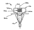
図7から図9までの例は、本発明に従って構成された更に別の弾性クリップ10bを示す。この弾性クリップ10bは、取付け用フランジ12b及び保持部分14bを含むように示されている。
Thus, while elastic clips have been shown and described above in the context of particular embodiments, those skilled in the art will appreciate that in a broader aspect, the invention can be configured somewhat differently. Will do. For example, as shown in FIG. 6, the fillet radius can be used at each
The examples of FIGS. 7-9 show yet another elastic clip 10b constructed in accordance with the present invention. The elastic clip 10b is shown to include a
取付け用フランジ12bは、ほぼU形状の本体部分200と、該本体部分200の両端に連結され、そこから下方に垂下するL形状の一対の脚部202とを含む。図8に最も良く示されるように、弾性クリップ10bが加工物構造体に挿入された時に該加工物構造体82bに接触するように、各々の脚部202の基部202aが構成され、該弾性クリップ10bが加工物構造体82bによって押し付けられるのを防止する。各々の脚部202の遠位端は、取付け用フランジ12bの横方向の中心線206に向けて内方に先細になる。与えられた特定の例においては、各々の脚部202と一体形成されたフック210を用いて、当該技術分野において周知の方法で該脚部202を互いに固定的に固定する。手短に言うと、一方の脚部202のフック210は、他方の脚部202の遠位端に掛かり、該フック210は、他方の脚部202を該フック210に固定するようにクランプされる。
The mounting
取付け用フランジ12bは、そこを貫通する、ファスナ(図示せず)を受けるためのアパーチャ(図示せず)を含むこともでき、又はファスナをねじ係合するように構成されるねじ要素220を含むことができる。与えられた例においては、ねじ要素220は、本体部分200と一体形成され、より具体的には、例えば順送りダイにおいて押し出され、ねじ込まれる。当業者であれば、他の技術を用いて、ねじ山形成を、図1の弾性クリップに関連して示される種類のケージ・ナット、溶接ナット、又は螺旋状リップのような本体部分200と関連付けできることを、この開示から理解するであろう。
保持部分14bは、各々の係合構造体30が、関連した脚部202の両側に配置された第1の構造体30a及び第2の構造体30bを含むことを除いて、図1の保持部分14と同様のものである。保持部分14bと保持部分14の間の類似性のために(上でかなり詳細に説明される)、保持部分についてさらに説明する必要はない。
The mounting
The retention portion 14b is the retention portion of FIG. 1 except that each
本発明は、明細書に説明され、好ましい実施形態に関連して図に示されたが、当業者であれば、特許請求の範囲に定められるような本発明の範囲から逸脱することなく、種々の変更をなし、均等物をその要素と置き換え得ることを理解するであろう。さらに、本発明の本質的な範囲から逸脱することなく、特定の状況又は材料を本発明の教示に適用するように、多くの修正をなすことができる。したがって、本発明は、本発明を実行するために現在のところ考えられる最良の形態として、図により示され、明細書に説明される特定の実施形態に限定されるものではなく、本発明は、前述の説明及び特許請求の範囲内に含まれるあらゆる実施形態を含むことが意図される。 While the invention has been described in the specification and shown in the drawings in connection with preferred embodiments, those skilled in the art will recognize that various changes can be made without departing from the scope of the invention as defined in the claims. Will be understood that equivalents may be substituted for the element. In addition, many modifications may be made to apply a particular situation or material to the teachings of the invention without departing from the essential scope thereof. Accordingly, the present invention is not limited to the specific embodiments shown in the drawings and described in the specification as the best mode presently contemplated for carrying out the invention. It is intended to include any embodiments contained within the foregoing description and claims.
10、10b:弾性クリップ
12、12b:フランジ
14、14b:保持部分
20:アパーチャ
22:ねじ付きファスナ
24:リップ
30:係合構造体
32:挿入軸線
36:係合タブ
38:ウィング部材
40:自由端
44:荷重分散要素
48:固定端
54、56、202:脚部
60:係合縁部
80、82:構造体
200:本体部分
10, 10b:
Claims (14)
前記係合構造体(30)の各々は、係合タブ(36)と一対のウィング部材(38)とを含み、
前記係合タブ(36)は、前記挿入軸線(32)から外方に付勢された自由端(40)及び前記自由端(40)と関連した荷重分散要素(44)を含み、
前記ウィング部材(38)は、関連した係合タブ(36)の前記自由端(40)から上方に、該挿入軸線(32)に向かう方向に延び、
前記ウィング部材(38)には、関連する前記係合タブ(36)の前記自由端(40)から上方に前記挿入軸線(32)の方向に延びる係合縁部(60)が末端に形成され、
前記ウィング部材は、前記係合縁部(60)の長さに沿った位置で、前記第1及び第2の構造体の一方に形成された孔の縁部(88)に相互係合して、該孔の縁部(88)から外れるのに抵抗するように作用し、
前記荷重分散要素(44)は、前記クリップ(10)に引抜き力が作用したとき、該引抜き力に応答して該第1及び第2の構造体の前記一方に接触し、該ウィング部材(38)が該第1及び第2の構造体の前記一方に接触する面積より実質的に広い面積にわたって前記引抜き力を分散させるようになった
ことを特徴とするクリップ(10)。 Fixing Ru a holding portion having a pair of engagement structures that are disposed on opposite sides of the axis of insertion (32) (30) (14), a first structure (80) to a second structure (82) A clip (10) for
Each of the engagement structures (30) includes an engagement tab (36) and a pair of wing members (38);
The engagement tab (36) includes a free end (40) biased outward from the insertion axis (32) and a load distribution element (44) associated with the free end (40) ;
The wing member (38) extends upward from the free end (40 ) of an associated engagement tab (36 ) in a direction toward the insertion axis (32) ;
The wing member (38) is formed at its distal end with an engagement edge (60) extending upwardly from the free end (40) of the associated engagement tab (36) in the direction of the insertion axis (32). ,
The wing member is engaged with an edge (88) of a hole formed in one of the first and second structures at a position along the length of the engagement edge (60). Acts to resist disengagement from the edge (88) of the hole,
The load distribution element (44) when the pulling force is applied to said clip (10), in contact with said one of the first and second structures in response to pultrusion force, the wing members (38 ) clip, characterized in that became so that substantially disperse the withdrawal force over a larger area than the area in contact with said one of the first and second structures (10).
Applications Claiming Priority (2)
| Application Number | Priority Date | Filing Date | Title |
|---|---|---|---|
| US10/651170 | 2003-08-28 | ||
| US10/651,170 US6976292B2 (en) | 2003-08-28 | 2003-08-28 | Resilient clip fastener |
Publications (2)
| Publication Number | Publication Date |
|---|---|
| JP2005076889A JP2005076889A (en) | 2005-03-24 |
| JP4718142B2 true JP4718142B2 (en) | 2011-07-06 |
Family
ID=34104728
Family Applications (1)
| Application Number | Title | Priority Date | Filing Date |
|---|---|---|---|
| JP2004249716A Active JP4718142B2 (en) | 2003-08-28 | 2004-08-30 | Elastic clip fastener |
Country Status (5)
| Country | Link |
|---|---|
| US (1) | US6976292B2 (en) |
| EP (1) | EP1510702B1 (en) |
| JP (1) | JP4718142B2 (en) |
| DE (1) | DE602004005789T2 (en) |
| ES (1) | ES2283915T3 (en) |
Families Citing this family (51)
| Publication number | Priority date | Publication date | Assignee | Title |
|---|---|---|---|---|
| US9457734B2 (en) * | 2001-06-25 | 2016-10-04 | Termax Corporation | Continuously adaptive fastener clip |
| US11603050B2 (en) | 2006-11-29 | 2023-03-14 | Termax Company | Spring fastener |
| US7226260B2 (en) * | 2002-06-24 | 2007-06-05 | A. Raymond, Inc. | Sheet metal fastening clip |
| US11261897B2 (en) * | 2003-11-17 | 2022-03-01 | Mag Daddy, LLC | Structural fastener |
| US11784428B2 (en) * | 2018-08-20 | 2023-10-10 | Mag Daddy Llc | Structural fastener |
| US9533718B2 (en) * | 2005-02-09 | 2017-01-03 | Termax Corporation | Continously adaptive fastener clip |
| DE102006032943B4 (en) * | 2005-07-18 | 2014-10-09 | Trw Automotive Electronics & Components Gmbh & Co. Kg | Vehicle grab handle |
| DE102005051678B4 (en) * | 2005-10-28 | 2008-06-12 | A. Raymond Et Cie | Device for attaching an attachment to a support part |
| DE102005060137B4 (en) * | 2005-12-16 | 2008-09-11 | A. Raymond Et Cie | Blechmutter |
| DE102005063028B3 (en) * | 2005-12-30 | 2007-05-10 | A. Raymond Et Cie | Device to fasten building part to carrying part has fastening clamp consisting of cover plate and clamping arms; cover plate held on support part moves between locked position when arms are locked onto part and free position with arms free |
| US7640707B2 (en) * | 2006-04-18 | 2010-01-05 | Illinios Tool Works Inc. | Fastening clip |
| DE102006019256B4 (en) * | 2006-04-26 | 2008-04-30 | A. Raymond Et Cie | fastening device |
| RU2403461C2 (en) * | 2006-04-26 | 2010-11-10 | А. Раймон Э Сие | Fastening device |
| US20070267884A1 (en) * | 2006-05-22 | 2007-11-22 | Lear Corporation | Grab handle systems for a vehicle |
| US7419206B2 (en) * | 2006-07-28 | 2008-09-02 | Newfrey Llc | Interior trim fastener system |
| US20080052878A1 (en) | 2006-08-31 | 2008-03-06 | Lewis Jeffrey C | Fastener Clip with Seal |
| US7753402B2 (en) * | 2006-10-09 | 2010-07-13 | Key Safety Systems, Inc. | Air bag assembly and clip therefor |
| DE102007005475B4 (en) * | 2007-01-30 | 2008-09-25 | C+M Utescheny Spritzgiesstechnik Gmbh | Fixing unit with a attachable to a support member fastener |
| US20090126168A1 (en) * | 2007-11-15 | 2009-05-21 | Kobe James J | Multi-Angle Pop-In Mechanical Fastener |
| DE102008021656B3 (en) * | 2008-04-30 | 2010-02-18 | A. Raymond Et Cie | Mounting bracket and arrangement with a mounting bracket and with an attachment |
| US8875357B2 (en) * | 2008-07-09 | 2014-11-04 | Tinnerman Palnut Engineered Products, Inc. | Clip |
| US8636454B2 (en) * | 2008-07-18 | 2014-01-28 | Piolax Inc. | Fastener |
| US7871102B2 (en) * | 2008-09-16 | 2011-01-18 | Newfrey Llc | Air bag fastener assembly |
| ES2356761B1 (en) * | 2009-07-31 | 2012-02-29 | Illinois Tools Works Inc. | ROOF CLIP FOR FIXING ACCESSORIES TO VEH� CULOS PANELS. |
| DE102009058815B4 (en) * | 2009-12-18 | 2022-05-19 | Volkswagen Ag | Holding device for add-on parts of vehicles |
| US8066316B2 (en) * | 2010-01-08 | 2011-11-29 | Ford Global Technologies | Adjustable mounting system for vehicular body components |
| DE102010007041A1 (en) * | 2010-02-05 | 2011-08-11 | Audi Ag, 85057 | Mounting system for lining of D-pillar of motor car, mounts liner part that is connected with carrier component by connectors and carrier elements over fastening regions, where regions correspond to variants of liner part regarding position |
| DE102010019685B4 (en) * | 2010-05-07 | 2016-11-24 | Audi Ag | Device for hanging objects |
| DE102011010141A1 (en) * | 2011-02-02 | 2012-08-02 | A. Raymond Et Cie S.C.S. | Fastening device for connecting attachment unit to support unit in airbag assembly, has inner wing and outer wing that are provided in two shaft arms that are connected to the cover plate |
| DE202011101112U1 (en) * | 2011-02-02 | 2012-08-28 | A. Raymond Et Cie | fastening device |
| EP2682616B1 (en) * | 2011-02-28 | 2015-09-16 | Honda Motor Co., Ltd. | Bracket with nut |
| JP5517167B2 (en) * | 2011-03-31 | 2014-06-11 | 豊田合成株式会社 | Clip for mounting components and mounting structure for components |
| WO2012166552A1 (en) | 2011-06-02 | 2012-12-06 | A. Raymond Et Cie | Fasteners manufactured by three-dimensional printing |
| US9097270B2 (en) * | 2013-07-26 | 2015-08-04 | GM Global Technology Operations LLC | Snap fit fastener |
| US9657759B2 (en) * | 2014-09-10 | 2017-05-23 | Newfrey Llc | U-based fastener with improved rib attachment |
| DE102015009366A1 (en) * | 2015-07-24 | 2017-01-26 | A.RAYMOND et Cie. SCS | Device for holding a component |
| AU2016373975B2 (en) * | 2015-12-14 | 2021-05-20 | Chatsworth Products, Inc. | Cage nut fastener and methods for tool-less installation of same |
| JP2017115978A (en) * | 2015-12-24 | 2017-06-29 | 大和化成工業株式会社 | clip |
| DE102016004337A1 (en) * | 2016-04-13 | 2017-10-19 | A.RAYMOND et Cie. SCS | Clip for attaching a first element to a second element |
| US10590968B2 (en) | 2018-03-01 | 2020-03-17 | Newfrey Llc | Dual component U-base fastener |
| US10894516B2 (en) * | 2017-10-18 | 2021-01-19 | Newfrey Llc | U-base fastener with folded barb and multiple spring arms |
| EP3581813B1 (en) * | 2018-06-13 | 2023-11-15 | Newfrey LLC | U-base fastener with folded barb and multiple spring arms |
| US11619324B2 (en) * | 2018-08-20 | 2023-04-04 | Mag Daddy, LLC | Structural fastener |
| US11466715B2 (en) | 2020-06-02 | 2022-10-11 | Lear Corporation | Connector assembly |
| US11622458B1 (en) | 2020-12-15 | 2023-04-04 | Chatsworth Products, Inc. | Brush port assembly and method for installing same |
| US11678456B1 (en) | 2020-12-15 | 2023-06-13 | Chatsworth Products, Inc. | Slidable mounting hardware for electronic equipment enclosure and method for installing same |
| US11818860B1 (en) | 2020-12-15 | 2023-11-14 | Chatsworth Products, Inc. | Frame structure for electronic equipment enclosure |
| US11639731B2 (en) * | 2021-01-29 | 2023-05-02 | A. Raymond Et Cie | Fastener clip |
| US11920392B1 (en) | 2021-02-02 | 2024-03-05 | Chatsworth Products, Inc. | Electrical bonding door hinges |
| US11909154B1 (en) | 2021-03-08 | 2024-02-20 | Chatsworth Products, Inc. | Endcap for establishing electrical bonding connection |
| US11746812B2 (en) | 2021-05-12 | 2023-09-05 | Newfrey Llc | Dual component sealing fastener and coupling assembly including same |
Citations (2)
| Publication number | Priority date | Publication date | Assignee | Title |
|---|---|---|---|---|
| EP0743461A1 (en) * | 1995-05-19 | 1996-11-20 | Elta Plastics Ltd. | Mounting device |
| JP2002031118A (en) * | 2000-03-27 | 2002-01-31 | Emhart Inc | Elastic clip stopper |
Family Cites Families (36)
| Publication number | Priority date | Publication date | Assignee | Title |
|---|---|---|---|---|
| US1873871A (en) | 1931-01-14 | 1932-08-23 | United Carr Fastener Corp | Snap fastener stud and installation thereof |
| US2032315A (en) | 1933-06-13 | 1936-02-25 | United Carr Fastener Corp | Rotary operative fastener installation and fastener for the same |
| US2086288A (en) | 1936-01-30 | 1937-07-06 | John H Van Uum | Spring clip |
| US2181966A (en) | 1937-07-08 | 1939-12-05 | Gen Motors Corp | Fastening device |
| GB571428A (en) | 1943-07-22 | 1945-08-23 | Tinnerman Products Inc | Improvements relating to screw and nut fastenings |
| US2509192A (en) | 1947-06-19 | 1950-05-23 | Illinois Tool Works | Drive fastener |
| US2618998A (en) | 1949-11-03 | 1952-11-25 | Illinois Tool Works | Molding clip |
| US2930090A (en) * | 1956-08-01 | 1960-03-29 | Robert L Brown | Fastener |
| US2885754A (en) * | 1956-12-05 | 1959-05-12 | Illinois Tool Works | Snap-in fastener |
| US2959259A (en) | 1958-09-15 | 1960-11-08 | Gen Motors Corp | Fastener device |
| US3400743A (en) | 1965-05-18 | 1968-09-10 | Tinnerman Products Inc | Sheet metal fastener with resilient arms |
| US3486202A (en) * | 1968-05-16 | 1969-12-30 | Illinois Tool Works | Snap-in fastener |
| US3795890A (en) * | 1972-06-07 | 1974-03-05 | Trw Inc | Terminal connector |
| SE401653B (en) | 1972-06-21 | 1978-05-22 | Springfix Befestigungstechnik | MOUNTING CLAMP FOR MOLDINGS WITH T-SHAPE ROCK |
| US3939752A (en) | 1974-12-23 | 1976-02-24 | Illinois Tool Works Inc. | Fastener structure |
| US4300865A (en) | 1979-07-11 | 1981-11-17 | Trw Inc. | Blind clip fastener |
| US4402118A (en) | 1981-09-28 | 1983-09-06 | Usm Corporation | Clip for securing a panel to a support |
| US4606688A (en) * | 1982-12-15 | 1986-08-19 | Eaton Corporation | Removable fastening assembly |
| US4610588A (en) | 1984-07-24 | 1986-09-09 | Trw, Inc. | Fastener clip |
| US4595325A (en) | 1984-09-28 | 1986-06-17 | Eaton Corporation | Self-locking prevailing torque fastener |
| JPS6217410A (en) | 1985-07-15 | 1987-01-26 | 株式会社ニフコ | Fastener for fixing two panel in contact surface manner |
| US4644612A (en) | 1986-05-30 | 1987-02-24 | Usm Corporation | Panel retainer |
| JPH0310408Y2 (en) | 1987-02-28 | 1991-03-14 | ||
| US4959325A (en) * | 1989-02-24 | 1990-09-25 | Micron Technology, Inc. | Reduction of electric field effect in the bird's beak region of a DRAM cell following expansion of active region through local encroachment reduction |
| US4925351A (en) | 1989-03-21 | 1990-05-15 | Trw, Inc. | Push-in fastener clip |
| US5857735A (en) | 1994-06-20 | 1999-01-12 | Irausa Ingenieria, S.A. | Self-supporting roof with built-in fittings directly mountable upon vehicle roofs |
| US5542158A (en) | 1994-09-12 | 1996-08-06 | Emhart Inc. | Grommet fastener assembly for automobiles |
| US5636891A (en) | 1995-06-07 | 1997-06-10 | Prince Corporation | Adjustable fastener |
| JP3160197B2 (en) | 1995-12-27 | 2001-04-23 | 本田技研工業株式会社 | Vehicle interior materials |
| US5774949A (en) | 1997-08-27 | 1998-07-07 | Eaton Corporation | Trim clip |
| US5991976A (en) | 1997-12-05 | 1999-11-30 | Prince Corporation | Assist handle mounting plate |
| US5919019A (en) | 1998-01-20 | 1999-07-06 | California Industrial Products, Inc. | Mid-panel nut |
| US6101686A (en) | 1998-03-17 | 2000-08-15 | Daimlerchrysler Corporation | Interior trim spring clip |
| US6095734A (en) | 1999-09-21 | 2000-08-01 | Transtechnology Corp. | Pushnut |
| KR20010059692A (en) | 1999-12-30 | 2001-07-06 | 이계안 | Modular clip |
| JP3699048B2 (en) | 2001-02-01 | 2005-09-28 | ハン イル エ ワ カンパニーリミテッド | Goods mounting clip |
-
2003
- 2003-08-28 US US10/651,170 patent/US6976292B2/en not_active Expired - Fee Related
-
2004
- 2004-08-25 DE DE602004005789T patent/DE602004005789T2/en active Active
- 2004-08-25 EP EP04020117A patent/EP1510702B1/en not_active Expired - Fee Related
- 2004-08-25 ES ES04020117T patent/ES2283915T3/en active Active
- 2004-08-30 JP JP2004249716A patent/JP4718142B2/en active Active
Patent Citations (2)
| Publication number | Priority date | Publication date | Assignee | Title |
|---|---|---|---|---|
| EP0743461A1 (en) * | 1995-05-19 | 1996-11-20 | Elta Plastics Ltd. | Mounting device |
| JP2002031118A (en) * | 2000-03-27 | 2002-01-31 | Emhart Inc | Elastic clip stopper |
Also Published As
| Publication number | Publication date |
|---|---|
| EP1510702A1 (en) | 2005-03-02 |
| JP2005076889A (en) | 2005-03-24 |
| US20050044672A1 (en) | 2005-03-03 |
| DE602004005789D1 (en) | 2007-05-24 |
| US6976292B2 (en) | 2005-12-20 |
| ES2283915T3 (en) | 2007-11-01 |
| EP1510702B1 (en) | 2007-04-11 |
| DE602004005789T2 (en) | 2008-01-10 |
Similar Documents
| Publication | Publication Date | Title |
|---|---|---|
| JP4718142B2 (en) | Elastic clip fastener | |
| US7849567B2 (en) | Spring fastener with highly improved removal to insertion ratio | |
| US11105354B2 (en) | Fastening clip | |
| US7878749B2 (en) | Breakaway W-base fastener | |
| KR20200051510A (en) | Fastener feedback feature | |
| US8210786B2 (en) | Fastening device | |
| EP2496848B1 (en) | Removable and reusable quick nut | |
| KR20110119697A (en) | Removable long-lived and reusable u-shaped hybrid nut | |
| KR102026241B1 (en) | Clip for perimeter trim | |
| EP0682186A1 (en) | Member mounting clip | |
| US2521317A (en) | Molding clip | |
| WO2020121712A1 (en) | Anchor plate and anchor device for seat belt webbing | |
| WO2012036048A1 (en) | Fastener for attaching component | |
| KR102184003B1 (en) | Bolt release prevention device | |
| JP2015052338A (en) | Resin clip | |
| WO2023085122A1 (en) | Fastener | |
| KR101984114B1 (en) | A clip with female thread function to fasten the screw to secure the assist handle to the bodywork panel | |
| JP2000079857A (en) | Installing structure of bumper for vehicle | |
| JP2592794Y2 (en) | Push-in nut | |
| JP2018050391A (en) | Harness fixing clip and wiring harness | |
| JP6663709B2 (en) | Fastener | |
| JPH10122433A (en) | Piping mounting bracket | |
| JP2577880Y2 (en) | Holding tool | |
| EP3213984A1 (en) | Mudguard device | |
| JPH074915U (en) | Stoppers with elastic support legs |
Legal Events
| Date | Code | Title | Description |
|---|---|---|---|
| A621 | Written request for application examination |
Free format text: JAPANESE INTERMEDIATE CODE: A621 Effective date: 20070521 |
|
| A977 | Report on retrieval |
Free format text: JAPANESE INTERMEDIATE CODE: A971007 Effective date: 20100917 |
|
| A131 | Notification of reasons for refusal |
Free format text: JAPANESE INTERMEDIATE CODE: A131 Effective date: 20100927 |
|
| A521 | Request for written amendment filed |
Free format text: JAPANESE INTERMEDIATE CODE: A523 Effective date: 20101220 |
|
| TRDD | Decision of grant or rejection written | ||
| A01 | Written decision to grant a patent or to grant a registration (utility model) |
Free format text: JAPANESE INTERMEDIATE CODE: A01 Effective date: 20110328 |
|
| A01 | Written decision to grant a patent or to grant a registration (utility model) |
Free format text: JAPANESE INTERMEDIATE CODE: A01 |
|
| A61 | First payment of annual fees (during grant procedure) |
Free format text: JAPANESE INTERMEDIATE CODE: A61 Effective date: 20110331 |
|
| R150 | Certificate of patent or registration of utility model |
Ref document number: 4718142 Country of ref document: JP Free format text: JAPANESE INTERMEDIATE CODE: R150 Free format text: JAPANESE INTERMEDIATE CODE: R150 |
|
| FPAY | Renewal fee payment (event date is renewal date of database) |
Free format text: PAYMENT UNTIL: 20140408 Year of fee payment: 3 |
|
| R250 | Receipt of annual fees |
Free format text: JAPANESE INTERMEDIATE CODE: R250 |
|
| R250 | Receipt of annual fees |
Free format text: JAPANESE INTERMEDIATE CODE: R250 |
|
| R250 | Receipt of annual fees |
Free format text: JAPANESE INTERMEDIATE CODE: R250 |
|
| R250 | Receipt of annual fees |
Free format text: JAPANESE INTERMEDIATE CODE: R250 |
|
| R250 | Receipt of annual fees |
Free format text: JAPANESE INTERMEDIATE CODE: R250 |
|
| R250 | Receipt of annual fees |
Free format text: JAPANESE INTERMEDIATE CODE: R250 |
|
| R250 | Receipt of annual fees |
Free format text: JAPANESE INTERMEDIATE CODE: R250 |
|
| R250 | Receipt of annual fees |
Free format text: JAPANESE INTERMEDIATE CODE: R250 |
|
| R250 | Receipt of annual fees |
Free format text: JAPANESE INTERMEDIATE CODE: R250 |
|
| R250 | Receipt of annual fees |
Free format text: JAPANESE INTERMEDIATE CODE: R250 |
|
| R250 | Receipt of annual fees |
Free format text: JAPANESE INTERMEDIATE CODE: R250 |