JP4717766B2 - Image display device, imaging device, image display method, storage medium, and program - Google Patents
Image display device, imaging device, image display method, storage medium, and program Download PDFInfo
- Publication number
- JP4717766B2 JP4717766B2 JP2006249958A JP2006249958A JP4717766B2 JP 4717766 B2 JP4717766 B2 JP 4717766B2 JP 2006249958 A JP2006249958 A JP 2006249958A JP 2006249958 A JP2006249958 A JP 2006249958A JP 4717766 B2 JP4717766 B2 JP 4717766B2
- Authority
- JP
- Japan
- Prior art keywords
- image
- face
- area
- display
- focus detection
- Prior art date
- Legal status (The legal status is an assumption and is not a legal conclusion. Google has not performed a legal analysis and makes no representation as to the accuracy of the status listed.)
- Expired - Fee Related
Links
Images


Classifications
-
- G—PHYSICS
- G03—PHOTOGRAPHY; CINEMATOGRAPHY; ANALOGOUS TECHNIQUES USING WAVES OTHER THAN OPTICAL WAVES; ELECTROGRAPHY; HOLOGRAPHY
- G03B—APPARATUS OR ARRANGEMENTS FOR TAKING PHOTOGRAPHS OR FOR PROJECTING OR VIEWING THEM; APPARATUS OR ARRANGEMENTS EMPLOYING ANALOGOUS TECHNIQUES USING WAVES OTHER THAN OPTICAL WAVES; ACCESSORIES THEREFOR
- G03B13/00—Viewfinders; Focusing aids for cameras; Means for focusing for cameras; Autofocus systems for cameras
-
- H—ELECTRICITY
- H04—ELECTRIC COMMUNICATION TECHNIQUE
- H04N—PICTORIAL COMMUNICATION, e.g. TELEVISION
- H04N23/00—Cameras or camera modules comprising electronic image sensors; Control thereof
- H04N23/60—Control of cameras or camera modules
- H04N23/61—Control of cameras or camera modules based on recognised objects
- H04N23/611—Control of cameras or camera modules based on recognised objects where the recognised objects include parts of the human body
-
- H—ELECTRICITY
- H04—ELECTRIC COMMUNICATION TECHNIQUE
- H04N—PICTORIAL COMMUNICATION, e.g. TELEVISION
- H04N23/00—Cameras or camera modules comprising electronic image sensors; Control thereof
- H04N23/60—Control of cameras or camera modules
- H04N23/63—Control of cameras or camera modules by using electronic viewfinders
- H04N23/631—Graphical user interfaces [GUI] specially adapted for controlling image capture or setting capture parameters
-
- H—ELECTRICITY
- H04—ELECTRIC COMMUNICATION TECHNIQUE
- H04N—PICTORIAL COMMUNICATION, e.g. TELEVISION
- H04N23/00—Cameras or camera modules comprising electronic image sensors; Control thereof
- H04N23/60—Control of cameras or camera modules
- H04N23/63—Control of cameras or camera modules by using electronic viewfinders
- H04N23/633—Control of cameras or camera modules by using electronic viewfinders for displaying additional information relating to control or operation of the camera
- H04N23/635—Region indicators; Field of view indicators
-
- H—ELECTRICITY
- H04—ELECTRIC COMMUNICATION TECHNIQUE
- H04N—PICTORIAL COMMUNICATION, e.g. TELEVISION
- H04N23/00—Cameras or camera modules comprising electronic image sensors; Control thereof
- H04N23/60—Control of cameras or camera modules
- H04N23/67—Focus control based on electronic image sensor signals
- H04N23/673—Focus control based on electronic image sensor signals based on contrast or high frequency components of image signals, e.g. hill climbing method
Landscapes
- Engineering & Computer Science (AREA)
- Multimedia (AREA)
- Signal Processing (AREA)
- Human Computer Interaction (AREA)
- Physics & Mathematics (AREA)
- General Physics & Mathematics (AREA)
- Studio Devices (AREA)
- Focusing (AREA)
- Indication In Cameras, And Counting Of Exposures (AREA)
- Automatic Focus Adjustment (AREA)
Description
本発明は、概して、画像表示装置、撮像装置、画像表示方法、記憶媒体、及び、プログラムに関する。本発明は、特に、画像撮像時に合焦のために使用された合焦領域に関連する画像を画像表示装置に表示させる技術に関する。 The present invention generally relates to an image display device, an imaging device, an image display method, a storage medium, and a program. In particular, the present invention relates to a technique for displaying an image related to a focus area used for focusing when an image is captured on an image display device.
デジタルカメラなどで撮像した画像(以下、「撮像画像」と呼ぶ)を、デジタルカメラのディスプレイやPC(パーソナルコンピュータ)のディスプレイなどに表示することにより、ユーザは、撮像時の合焦状態を確認することができる。しかし、撮像時に合焦のために使用される焦点検出領域は、一般的に極めて小さいため、撮像画像全体をディスプレイに表示すると、ユーザは、焦点検出領域において正しく合焦しているかを確認することが容易ではない。 By displaying an image captured by a digital camera or the like (hereinafter referred to as “captured image”) on a display of a digital camera or a PC (personal computer), the user confirms the in-focus state at the time of imaging. be able to. However, since the focus detection area used for focusing at the time of imaging is generally extremely small, when the entire captured image is displayed on the display, the user must check whether the focus detection area is correctly focused. Is not easy.
そこで、撮像後や撮像時に、焦点検出領域の画像をディスプレイに拡大表示することにより、ユーザによる合焦状態の確認を容易にする技術が提案されている(特許文献1及び2参照)。 In view of this, a technique has been proposed that facilitates confirmation of the in-focus state by the user by enlarging and displaying the image in the focus detection area on the display after or during imaging (see Patent Documents 1 and 2).
また、特許文献1及び2に見られるように、従来の撮像装置では、1以上の焦点検出領域が撮像領域中に予め設定されていた。しかし、人物が被写体の場合に、人物が撮像領域中のどこに位置しても適切に人物に合焦できるようにしたいという要求がある。そこで、撮像領域において被写体としての人物の顔(以下、単に「顔」と呼ぶ)を検出し、検出された顔の近傍に焦点検出領域を設定する技術が提案されている(特許文献3及び4参照)。
従来の技術においては、合焦状態を確認するための画像をディスプレイに表示する際に、焦点検出領域が顔に基づいて設定されたものであるか否かは考慮されていなかった。しかし、焦点検出領域が顔に基づいて設定されたものであるか否かによって、合焦状態の確認に適した画像は異なる。 In the related art, when an image for confirming the in-focus state is displayed on the display, it is not considered whether or not the focus detection area is set based on the face. However, the image suitable for checking the in-focus state differs depending on whether or not the focus detection area is set based on the face.
本発明はこのような状況に鑑みてなされたものであり、焦点検出領域が顔に基づいて設定されたものであるか否かに関わらず、撮像画像の合焦状態の確認に好適な拡大画像を画像表示装置に表示させる技術を提供することを目的とする。 The present invention has been made in view of such circumstances, and an enlarged image suitable for confirming the in-focus state of a captured image regardless of whether or not the focus detection region is set based on a face. An object of the present invention is to provide a technique for displaying an image on an image display device.
上記課題を解決するために、第1の本発明によれば、撮像の際に使用された焦点検出領域に関する情報を含む撮像画像を取得する取得手段と、前記焦点検出領域が撮像の際に検出された被写体の顔に基づいて決定されている場合、被写体の顔に関する情報に基づく、前記焦点検出領域とは異なる領域を撮像画像から抽出し、前記焦点検出領域が被写体の顔に基づいて決定されていない場合、前記焦点検出領域に一致する領域を撮像画像から抽出する抽出手段と、前記抽出した領域の画像を表示部に表示する表示手段と、を備えることを特徴とする画像表示装置が提供される。 In order to solve the above problems, according to a first aspect of the present invention, an acquisition unit configured to acquire a captured image including the information about the focus detection area is used during an imaging, the focus detection area in the image capture A region different from the focus detection region based on information on the subject's face is extracted from the captured image, and the focus detection region is based on the subject's face. If not determined, an image display apparatus comprising: an extraction unit that extracts a region that matches the focus detection region from a captured image; and a display unit that displays an image of the extracted region on a display unit. Is provided.
また、第2の本発明によれば、焦点検出領域の出力信号に基づいて焦点調節され撮像された撮像画像を取得する取得手段と、取得した前記撮像画像の一部を表示部に表示する表示手段とを備え、前記表示手段が、前記焦点検出領域が撮影の際に検出された被写体の顔の位置に対応して決定された場合は撮像画像に対して第1の割合の、前記焦点検出領域とは異なる領域を抽出して表示部に表示し、前記焦点検出領域が被写体の顔の位置に対応して決定されていない場合は前記焦点検出領域に一致する領域を抽出して表示部に表示することを特徴とする画像表示装置が提供される。 Further, according to the second invention, an acquisition unit for acquiring a captured image captured is focusing on the basis of the focus point detection output signal of the area is displayed on the display unit a part of the acquired imaged image and display means, said display means, the first rate with respect to the captured image if the focus detection area is determined in accordance with the position of the face of the detected subject during shooting, the focus displayed on the display unit extracts a region different from the detection region, when the focus detection area is not determined to correspond to the position of the face of the Utsushitai extracts the region that matches the focus detection area An image display device characterized by displaying on a display unit is provided.
また、第4の本発明によれば、画像処理装置による画像表示方法であって、撮像の際に使用された焦点検出領域に関する情報を含む撮像画像を取得する取得ステップと、前記焦点検出領域が撮像の際に検出された被写体の顔に基づいて決定されている場合、被写体の顔に関する情報に基づく、前記焦点検出領域とは異なる領域を撮像画像から抽出し、前記焦点検出領域が被写体の顔に基づいて決定されていない場合、前記焦点検出領域に一致する領域を撮像画像から抽出する抽出ステップと、前記抽出した領域の画像を表示部に表示する表示ステップと、を備えることを特徴とする画像表示方法が提供される。 According to the fourth aspect of the present invention, an image display method by the image processing apparatus, an acquisition step of acquiring a captured image including the information about the focus detection area is used during an imaging, pre SL focus When the detection area is determined based on the face of the subject detected at the time of imaging, an area different from the focus detection area based on information on the face of the subject is extracted from the captured image, and the focus detection area is If not determined based on the face of the subject, further comprising an extraction step of extracting an area that matches the focus detecting area from the captured image, and a display step of displaying an image before Symbol extracted area on the display unit, the An image display method is provided.
また、第5の本発明によれば、画像処理装置による画像表示方法であって、焦点検出領域の出力信号に基づいて焦点調節され撮像された撮像画像を取得する取得ステップと、取得した前記撮像画像の一部を表示部に表示する表示ステップとを備え、前記表示ステップにおいて、前記焦点検出領域が撮影の際に検出された被写体の顔の位置に対応して決定された場合は撮像画像に対して第1の割合の、前記焦点検出領域とは異なる領域を抽出して表示部に表示し、前記焦点検出領域が被写体の顔の位置に対応して決定されていない場合は前記焦点検出領域に一致する領域を抽出して表示部に表示することを特徴とする画像表示方法が提供される。 In addition, according to the fifth invention, an image display method by the image processing apparatus, an acquisition step of acquiring a captured image captured it is focusing on the basis of the output signal of the focus point detection region, and acquisition and a display step of displaying a portion of the captured image, before Symbol display step, when said focus detecting area is determined to correspond to the position of the face of the detected subject during shooting of the first rate with respect to the captured image, the display on the display unit extracts a region different from the focus detection area, when the focus detection area is not determined to correspond to the position of the face of the Utsushitai An image display method is provided, wherein an area matching the focus detection area is extracted and displayed on a display unit.
尚、その他の本発明の特徴は、添付図面及び以下の発明を実施するための最良の形態における記載によってさらに明らかになるものである。 Other features of the present invention will become more apparent from the accompanying drawings and the following description of the best mode for carrying out the invention.
以上の構成により、本発明によれば、焦点検出領域が顔に基づいて設定されたものであるか否かに関わらず、撮像画像の合焦状態の確認に好適な拡大画像を画像表示装置に表示させることが可能となる。 With the above configuration, according to the present invention, an enlarged image suitable for confirming the in-focus state of the captured image is displayed on the image display device regardless of whether the focus detection area is set based on the face. It can be displayed.
以下、添付図面を参照して、本発明の実施形態を説明する。以下で説明される個別の実施形態は、本発明の上位概念、中位概念および下位概念など種々の概念を理解するために役立つであろう。 Embodiments of the present invention will be described below with reference to the accompanying drawings. The individual embodiments described below will help to understand various concepts, such as the superordinate concept, intermediate concept and subordinate concept of the present invention.
尚、本発明の技術的範囲は、特許請求の範囲によって確定されるのであって、以下の個別の実施形態によって限定されるわけではない。また、実施形態の中で説明されている特徴の組み合わせすべてが、本発明に必須とは限らない。 The technical scope of the present invention is determined by the scope of the claims, and is not limited by the following individual embodiments. In addition, not all combinations of features described in the embodiments are essential to the present invention.
<デジタルカメラ100の構成>
本発明の画像表示装置をデジタルカメラ100に適用した実施形態について説明する。
<Configuration of
An embodiment in which the image display apparatus of the present invention is applied to a
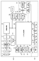
図1は、本実施形態に係るデジタルカメラ100の構成を示すブロック図である。
FIG. 1 is a block diagram illustrating a configuration of a
図1において、10は変倍レンズ、11は焦点調節レンズ、12は入射光を遮断するメカニカルシャッタ、13は入射光の光量を調節する絞り、14は撮像素子である。また、15は撮像素子14を駆動し、かつ、サンプリングに必要なタイミングパルスを発生するタイミング発生器である。また、16は撮像素子14の出力をタイミング発生器15のタイミングパルスに基づいて二重相関サンプリングを行うCDS素子、17はCDS素子16の出力であるアナログ信号をデジタル信号に変換するA/D変換器である。
In FIG. 1, 10 is a variable power lens, 11 is a focus adjustment lens, 12 is a mechanical shutter that blocks incident light, 13 is a diaphragm that adjusts the amount of incident light, and 14 is an image sensor.
ここで、本実施形態においては、撮像素子としてCCDを用いるものとして説明するが、CMOSセンサを用いても構わない。 Here, in the present embodiment, a description will be given on the assumption that a CCD is used as an imaging device, but a CMOS sensor may be used.
18は、A/D変換器17が出力する画像データとしてのデジタル信号に各種画像処理を施すための、信号処理回路、顔検出回路、縮小回路、ラスタブロック変換回路、及び、圧縮回路等(各回路は不図示)を含む画像処理部である。
信号処理回路は、A/D変換器17が出力するデジタル信号に、色キャリア除去、アパーチャー補正、ガンマ補正処理等を行って輝度信号を生成すると同時に、色補間、マトリックス変換、ガンマ処理、ゲイン調整等を施して色差信号を生成する。そして、メモリ部26にYUV形式の画像データを形成する。
The signal processing circuit performs color carrier removal, aperture correction, gamma correction processing, etc. on the digital signal output from the A /
縮小回路は、信号処理回路の出力する画像データに対し、画素データの切り出し、間引き、及び、線形補間処理等を行い、水平垂直両方向に画像を縮小してラスタスキャン画像データを生成する。これは、取得した画像よりも小さな画像を記憶媒体32に記憶したいというユーザの要求を満たすためである。従って、ユーザが画像の縮小を望まない場合は、縮小回路は画像の縮小を行わない。
The reduction circuit performs pixel data cutout, thinning, linear interpolation processing, and the like on the image data output from the signal processing circuit, and reduces the image in both horizontal and vertical directions to generate raster scan image data. This is to satisfy the user's request to store an image smaller than the acquired image in the
ラスタブロック変換回路は、縮小回路で縮小されたラスタスキャン画像データをブロックスキャン画像データに変換する。 The raster block conversion circuit converts the raster scan image data reduced by the reduction circuit into block scan image data.
圧縮回路は、ラスタブロック変換回路でブロックスキャン画像データに変換された画像データをブロック単位でJPEGデータに圧縮する。 The compression circuit compresses the image data converted into the block scan image data by the raster block conversion circuit into JPEG data in units of blocks.
顔検出回路は、信号処理回路が出力したYUV形式の画像データなどを用いて、撮像領域中に存在する顔を検出する。顔検出回路とそれを用いた顔検出処理の詳細は、図2を参照して後述する。 The face detection circuit detects a face existing in the imaging region using YUV format image data output from the signal processing circuit. Details of the face detection circuit and face detection processing using the face detection circuit will be described later with reference to FIG.
こうした一連の画像処理には、メモリ26がバッファメモリとして用いられる。
In such a series of image processing, the
これらの処理の制御は、CPUとそのインターフェイス回路、DMAC(Direct Memory Access Controller)、バスアービター等で構成されるシステム制御回路60によって行われる。CPUが実行するプログラムは、フラッシュメモリ25に記憶されている。
The control of these processes is performed by a
19は、メカニカルシャッタ12、絞り13を制御する露出制御部であり、20は、変倍レンズ10、焦点調節レンズ11を光軸上に沿って移動させ、被写界像を撮像素子14上に結像させるレンズ制御部である。21は、ユーザに画角設定を行わせるためのT/Wスイッチであり、22は、ユーザがデジタルカメラ100の動作モードを設定するためのモードダイヤルである。T/Wスイッチ21の操作により行われる画角設定には、変倍レンズの移動による光学ズームと、撮像素子14の駆動と撮像素子の出力に対する画像処理による電子ズームとがあり、両方のズームにT/Wスイッチ21は共用される。また、T/Wスイッチ21は、後述する合焦近傍位置の拡大率を変更するためにも使用され得る。
23は、ユーザが画像(静止画像)の撮像指示を行うためのレリーズスイッチであり、24は、モニタ51における画像の表示/非表示等を切り替えるDISPスイッチである。レリーズスイッチ23はダブルアクションスイッチで、2段階のポジションを持つ。第一段階(半押し)まで押下されると、デジタルカメラ100は撮像準備を行い、第二段階(全押し)まで押下されると、デジタルカメラ100は撮像を行う。
42は電池等を含む電源、70と41はデジタルカメラ100と電池42とを係合させるコネクタ、40は電源42を保持する電源BOX、32は画像を記憶する記憶媒体である。28と31は、デジタルカメラ100と記憶媒体32とを係合させるコネクタ、33は記憶媒体32の書き込み禁止スイッチの状態を検知する禁止検知部、29は記憶媒体32の着脱を検知する着脱検知部である。
80は、モニタ51上に表示されるメニュー画面やEVF(電子ビューファインダ)表示と同時に表示されるカーソルの移動等に使用される上下左右スイッチ及び決定スイッチ等が配置された複合スイッチである。複合スイッチ81は、静止画撮影時にモニタ51上に表示された画角設定に対して、静止画として撮影記録される画角を設定するためにも使用される。81は、モード毎の各種設定を行うためのメニュー画面をモニタ51に表示させるメニュースイッチであり、後述する焦点位置の拡大表示において、合焦位置を切り替える時にも使用される。
50は再生回路であり、画像処理部18で生成され、メモリ部26に記憶された画像データを表示用画像に変換してモニタ51に転送する。51はモニタである。再生回路50は、YUV形式の画像データを輝度成分信号Yと変調色差成分Cとに分離し、D/A変換によりアナログ信号に変換されたY信号をLPF(ローパスフィルタ)に通す。また、D/A変換されたアナログC信号をBPF(バンドパスフィルタ)に通し、変調色差成分の周波数成分のみを抽出する。再生回路50は、こうして生成した信号成分とサブキャリア周波数に基づいて、Y信号とC信号をRGB信号に変換し、モニタ51に出力する。撮像素子からの画像データをこのように逐次処理してモニタ51に表示すれば、EVF機能が実現される。
A
<顔検出回路及び顔検出処理>
図2は、画像処理部18内の、被写体としての人物の顔を検出する顔検出回路の構成を示すブロック図である。
<Face detection circuit and face detection processing>
FIG. 2 is a block diagram illustrating a configuration of a face detection circuit that detects the face of a person as a subject in the
入力される信号は、信号処理回路の出力YUV形式の画像データ或いは、JPEG伸張され、メモリ26にバッファリングされたYUV形式の画像データが選択可能である。入力されたYUV形式の画像データは、画像変換部18−aで一旦、所定サイズの画像に変換される。ここでいう所定サイズは、後に行われるパターン比較の処理スピードと顔の検出制度に影響を与えるものである。
本実施形ではQVGAサイズ(320×240)とするが、これに限定されるものではない。その後、画像抽出部18−bにおいて所望領域が切り出され、中間画像が生成される。ここでいう所望領域は、入力画像に対して顔検出を行う対象領域を決定するものである。本件では、主被写体となる人物が被写界周辺には存在しないものとして、画面中心画角80%を所望領域とするが、これに限定されるものではない。中間画像は一時メモリ18−cに記憶される。中間画像を一時的に記憶するメモリは26を併用してもよい。次に、特徴抽出部18−dにおいて輝度抽出および、フィルタ処理を行う。その結果とパターン比較を行って、例えば、顔の座標、顔のサイズ、目の座標、目のサイズ、及び、顔の信頼度を被写体の顔に関する情報である顔検出情報として出力する。尚、顔検出時のパターン比較を行う場合において、検出する顔の最大個数や、顔として認識する画素サイズを設定することができる。
As the input signal, it is possible to select YUV format image data output from the signal processing circuit or YUV format image data that has been JPEG decompressed and buffered in the
In the present embodiment, the QVGA size (320 × 240) is used, but the present invention is not limited to this. Thereafter, a desired area is cut out by the image extraction unit 18-b, and an intermediate image is generated. The desired area referred to here is used to determine a target area for performing face detection on the input image. In this case, assuming that the person who is the main subject does not exist in the vicinity of the object scene, the screen center angle of view of 80% is set as the desired region, but the present invention is not limited to this. The intermediate image is stored in the temporary memory 18-c. The memory for temporarily storing the intermediate image may be 26. Next, luminance extraction and filter processing are performed in the feature extraction unit 18-d. The pattern is compared with the result, and, for example, face coordinates, face size, eye coordinates, eye size, and face reliability are output as face detection information that is information about the face of the subject. When performing pattern comparison at the time of face detection, the maximum number of faces to be detected and the pixel size recognized as a face can be set.
ここで、撮像領域中に複数の顔が検出された場合は、複数の顔検出情報が顔検出回路から出力される。一方、撮像領域中に顔が検出されなかった場合は、顔が検出されなかった旨を示す顔検出情報(例えば、顔のサイズが0である顔検出情報など)が出力される。 Here, when a plurality of faces are detected in the imaging region, a plurality of face detection information is output from the face detection circuit. On the other hand, when a face is not detected in the imaging region, face detection information (for example, face detection information whose face size is 0) indicating that no face has been detected is output.
<デジタルカメラ100の外観>
図3は、デジタルカメラ100の外観の一部を示す図である。図3に示すように、デジタルカメラ100の外部には、T/Wスイッチ21、レリーズスイッチ23、DISPスイッチ24、メニュースイッチ81、複合スイッチ80が見られる。ユーザは、T/Wスイッチ21の中心の突起を指の先端で矢印方向に操作することによって、変倍レンズ10をTele(望遠)側若しくは、Wide(広角)側に移動させることが出来る。T/Wスイッチ21の操作環は、内蔵の可変抵抗に接続され(不図示)、スイッチ操作で一義的に決定される電圧値をシステム制御回路60のA/D変換器に入力し、入力された電圧値はデジタル信号に変換される。システム制御回路60内のCPUとプログラムじゃ、T/Wスイッチ21の操作に応じて、変倍レンズ10の移動速度を制御することができる。例えば、10bitのA/D変換器で、中心を511LSBとして±255は低速領域、±256以上は高速領域とするなどが考えられる。速度分割は2分割に限定されるものではない。
<Appearance of
FIG. 3 is a view showing a part of the appearance of the
撮像素子14の単位画素には、R、G、Bの色相フィルタがあり、ベイヤ配列を成している。静止画を撮影する場合などには、有効領域の殆ど全ての画素を読み出して画像生成を行う。CCDの場合には、先幕としてフォトダイオード(以後、「PD」と呼ぶ)の電荷を掃き捨てる。その後、後幕としてメカニカルな遮蔽部材によるシャッタを閉じて光路を断った後、PDに蓄積した一面分の電荷をCCDの垂直転送レジスタに移し、1ラインずつ読み出して行われる。CMOSの場合には、各画素のPDと共に、PDで発生した電荷を一時的に蓄積しておく蓄積領域となるフローティング・デフュージョン(以下、FD)の電荷を一括してリセットし、行単位で読み出しを行う一括リセット読み出しが行われる。この時も後幕にはメカニカルな遮光部材によるシャッタが用いられる。そして、得られた画像データは一旦メモリ26に保存され、画像処理部にて前述の信号処理が行われる。
The unit pixel of the
一方、EVF表示や動画撮影を行う場合、その性質上、画素数が表示用画像生成に必要な画素数近辺になるように間引いたり、加算平均したりして撮像素子14から読み出され、出力される画像データを逐次画像処理して実現される。CMOSの場合には画素若しくは、行単位でPD及び、FDに蓄積された電荷をリセットした後、画素若しくは、行単位で順次読み出すことによって、行単位の蓄積時間を一定に保ちながら連続的に電荷を読み出す走査で実現する。また、CCDの場合には、面単位でPDの電荷を掃き捨て、面単位で垂直転送路に移して読み出して実現する。 On the other hand, when EVF display or moving image shooting is performed, the number of pixels is thinned out or added and averaged so that the number of pixels is close to the number of pixels necessary for display image generation. This is realized by sequentially processing the image data to be processed. In the case of CMOS, after resetting the charge accumulated in PD and FD in pixel or row units, by sequentially reading out in pixel or row units, the charge is continuously charged while keeping the accumulation time in row units constant. This is realized by scanning. In the case of a CCD, the charge of the PD is swept away in units of planes, transferred to a vertical transfer path in units of planes, and read.
<撮像処理の流れ>
図4は、デジタルカメラ100を用いた撮像処理の流れを示すフローチャートである。以下に説明する各フローチャートの各ステップは、特に断らない限り、システム制御部60がフラッシュメモリ25に格納されているプログラムを実行することにより実現される。
<Flow of imaging processing>
FIG. 4 is a flowchart showing a flow of imaging processing using the
まず、モードダイヤル22が撮影モードに設定されると、デジタルカメラ100は、撮影モードに入り、ステップS401で、モニタ51におけるEVF表示を開始する。EVF表示は、後述する図5のステップS509において終了されるまで継続する。
First, when the
ステップS402で、デジタルカメラ100は、表示領域における顔検出処理を開始する。顔検出処理により、撮像領域中に検出された顔の数だけ顔検出情報が取得され、メモリ部26に格納される。顔検出処理は、後述する図5のステップS501における処理が行われるまで随時実行され、メモリ部26に格納される顔検出情報が更新される。
In step S402, the
ステップS403で、デジタルカメラ100は、モードダイヤル22が操作されたか否かを判定する。モードダイヤル22が操作された場合、本フローチャートの処理は終了し、デジタルカメラ100は操作後のモードに対応する処理を行う。モードダイヤル22が操作されなければ、ステップS404に進む。
In step S403, the
ステップS404で、デジタルカメラ100は、レリーズスイッチ23が半押し状態になったか否かを判定する。半押し状態になった場合はステップS405に進み、そうでなければステップS401に戻る。
In step S404, the
ステップS405で、デジタルカメラ100は、静止画像を撮像し、ステップS401に戻る。画像の撮像処理の詳細は図5を参照して後述する。
In step S405, the
図5は、図4のステップS405における画像の撮像処理の詳細な流れを示すフローチャートである。 FIG. 5 is a flowchart showing a detailed flow of the image capturing process in step S405 of FIG.
ステップS501で、デジタルカメラ100は、顔検出処理を終了し、その時点でメモリ部26に格納されている顔検出情報(顔の座標、顔のサイズ、目の座標、目のサイズ、及び、顔の信頼度)を最終的な顔検出結果として確定させる。尚、顔が検出されなかった場合、前述のように、顔が検出されなかった旨を示す顔検出情報(例えば、顔のサイズが0である顔検出情報など)がメモリ部26に格納されている。
In step S501, the
ステップS502で、デジタルカメラ100は、顔検出情報を参照して、撮像領域中に顔が検出されたか否かを判定する。顔が検出された場合、ステップS503に進み、顔が検出されなかった場合、ステップS504に進む。
In step S502, the
ステップS503で、デジタルカメラ100は、検出された顔の位置に基づいて(詳細は図6を参照して後述)撮像領域中に焦点検出領域を設定する。そして、焦点調節レンズ11を移動させることにより、設定した焦点検出領域に対して焦点検出を行う。次いで、優先順位が最も高い顔に対応する焦点検出領域に合焦する位置に焦点調節レンズ11を移動させる。併せて、優先順位が最も高い顔と同じ被写界深度に存在する顔に対応する焦点検出領域(合焦領域)を、焦点検出の結果に基づいて求める。ここで、優先順位は、顔検出情報に基づいて決定されるものであり、例えば、顔のサイズが大きくて撮像領域の中央付近の顔ほど優先順位が高くなる。また、検出された全ての顔に対応して焦点検出領域を設定する必要は無く、例えば、優先順位が上位3つの顔のみの位置に基づいて焦点検出領域を設定してもよい。
In step S503, the
ステップS504で、デジタルカメラ100は、焦点調節レンズ11を移動させることにより、撮像領域中に予め設定された9つの焦点検出領域に対して焦点検出を行う。次いで、所定の条件に基づいて選択された焦点検出領域に合焦する位置に焦点調節レンズ11を移動させる。併せて、所定の条件に基づいて選択された焦点検出領域の被写体と同じ被写界深度に被写体が存在する焦点検出領域(合焦領域)を、焦点検出の結果に基づいて求める。
In step S504, the
ステップS505で、デジタルカメラ100は、合焦領域に対応する顔の顔検出情報(ステップS503が実行された場合)、又は、顔が検出されなかった旨を示す顔検出情報(ステップS504が実行された場合)をメモリ部26に格納する。
In step S505, the
ステップS506で、デジタルカメラ100は、ステップS503又はS504において合焦領域として求められた各焦点検出領域の座標、サイズ、及び、評価値(以下、「合焦情報」と呼ぶ)をメモリ部26に格納する。ここで、評価値とは、焦点検出の際に行われるコントラスト演算によって得られるコントラスト値である。
In step S506, the
ステップS507で、デジタルカメラ100は、合焦領域を示す矩形枠(合焦枠)をモニタ51に表示する。
In step S <b> 507, the
ステップS503乃至S507における、焦点検出領域と合焦領域との関係は、図6乃至図8を参照して後述する。 The relationship between the focus detection area and the focus area in steps S503 to S507 will be described later with reference to FIGS.
ステップS508で、デジタルカメラ100は、レリーズスイッチ23が全押しされるのを待つ。
In step S508, the
ステップS509で、デジタルカメラ100は、EVF表示を終了する。
In step S509, the
ステップS510で、デジタルカメラ100は、撮像処理を行い、画像処理部18は、A/D変換器17から画像データとしてのデジタル信号を取得する。
In step S <b> 510, the
ステップS511で、デジタルカメラ100は、画像処理部18により画像データの圧縮処理等を行い、JPEG画像データを得る。
In step S511, the
ステップS512で、デジタルカメラ100は、ステップS505で格納した顔検出情報とステップS506で格納した合焦情報とを、ステップS511で得たJPEG画像データのヘッダに記録し、記憶媒体32に格納する。
In step S512, the
ステップS513で、デジタルカメラ100は、ステップS512で格納したJPEG画像データをモニタ51に表示するためのデータ(以下、「レビュー表示用データ」と呼ぶ)を生成し、表示する。レビュー表示用データの生成/表示処理の詳細は、図10を参照して後述する。
In step S513, the
ここで、ステップS513の処理は、ステップS507においても同様に実行されても構わない。これにより、ユーザは、画像撮像前に合焦状態を確認することがより容易になる。 Here, the process of step S513 may be similarly executed in step S507. This makes it easier for the user to check the in-focus state before capturing an image.
<焦点検出領域と合焦領域>
図6乃至図8は、図5のステップS503乃至S507における、焦点検出領域と合焦領域との関係を示す図である。
<Focus detection area and focus area>
6 to 8 are diagrams illustrating the relationship between the focus detection area and the focus area in steps S503 to S507 in FIG.
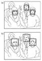
図6を参照して、撮像領域中に顔が1つ含まれる場合を説明する。図6(a)において、実線の矩形枠は顔検出枠(図4のステップS402において顔と検出された領域を示す枠)である。また、破線の矩形枠は、焦点検出枠(焦点検出領域を示す枠)である。顔検出枠及び焦点検出枠は、モニタ51には表示されない。図6(b)は、図6(a)の顔周辺を拡大した図である。顔検出枠は、顔検出回路で検出された顔の座標を含み、少なくとも目、鼻、口が含まれる程度の大きさである。図6(a)、(b)に示す焦点検出枠に合焦した場合、この焦点検出枠が示す焦点検出領域が、合焦領域となる。そして、図6(c)に示すように、合焦枠がモニタ51に表示される。合焦枠は、顔と重ならないように、合焦領域よりも大きく表示されることが好ましい。即ち、合焦枠は、合焦領域とは必ずしも一致しない。
A case where one face is included in the imaging region will be described with reference to FIG. In FIG. 6A, a solid-line rectangular frame is a face detection frame (a frame indicating a region detected as a face in step S402 in FIG. 4). Also, the dashed rectangular frame is a focus detection frame (frame indicating a focus detection area). The face detection frame and the focus detection frame are not displayed on the
図7は、撮像領域中に顔が複数(ここでは、4つ)含まれる場合を示す。前述のように、顔の優先順位が上位3つの顔に焦点検出領域が設定される(図7(a)参照)。また、設定された焦点検出領域における焦点検出の結果、3つ全ての焦点検出領域に合焦した場合は、それぞれの焦点検出領域が合焦領域となる。そして、図7(b)に示すように、3つの顔に対応する合焦領域に対して合焦枠が表示される。 FIG. 7 shows a case where a plurality of (here, four) faces are included in the imaging region. As described above, focus detection areas are set for the top three faces with the highest priority order (see FIG. 7A). Further, as a result of focus detection in the set focus detection area, when all three focus detection areas are focused, each focus detection area becomes the focus area. And as shown in FIG.7 (b), a focusing frame is displayed with respect to the focusing area | region corresponding to three faces.
図8は、撮像領域中に顔が含まれない(或いは、含まれても検出されなかった場合)を示す。この場合、焦点検出領域は、図8(a)に破線で示されるような、予め設定された9箇所の領域である。図8(a)の破線の枠は、モニタ51には表示されない。焦点検出の結果、合焦した焦点検出領域(合焦領域)には、図8(b)に示すような合焦枠がモニタ51に表示される。ここで、顔が検出された場合と異なり、合焦枠と合焦領域とは一致する。
FIG. 8 shows that a face is not included in the imaging region (or when it is included but not detected). In this case, the focus detection areas are nine predetermined areas as indicated by broken lines in FIG. The broken line frame in FIG. 8A is not displayed on the
<レビュー表示の概要>
撮像画像をモニタ51に表示するレビュー表示には、数種類のタイプが用意されており、ユーザの指示に応じて切り替えられる。レビュータイプの切り替えには、DISPスイッチスイッチ24が使用される。いくつかのレビュータイプにおいては、合焦領域に関連する画像が拡大表示される。合焦領域が複数ある場合には、例えば、評価値が最も高い合焦領域に関連する画像が拡大表示される。或いは、合焦領域が顔に基づくものである場合は、例えば、信頼度が最も高い顔に対応する合焦領域に関連する画像が拡大表示されてもよい。そして、ユーザの指示に応じて、表示する拡大画像に対応する合焦領域を、例えば、評価値(或いは信頼度など)の順に切り替える。合焦領域の切り替えには、メニュースイッチ81が使用される。
<Overview of review display>
There are several types of review displays for displaying captured images on the
図9は、撮像画像のレビュー表示の概要を示す図である。本実施形態では、画像撮像後のレビュー表示の際に、撮像画像全体と、撮像画像の一部を拡大した画像(拡大画像)が、種々の配置でモニタ51に表示される。図9においては、説明のために、モニタ51の表示サイズを320×240(単位はピクセル、以下同様)とする。
FIG. 9 is a diagram showing an outline of a review display of captured images. In the present embodiment, at the time of review display after imaging, the entire captured image and an image (enlarged image) obtained by enlarging a part of the captured image are displayed on the
図9(a)は、撮像画像の全体を示す全体画像をモニタ51全体に表示するレビュータイプ(以下、「タイプA」と呼ぶ)を示す。
FIG. 9A shows a review type (hereinafter referred to as “type A”) in which an entire image showing the entire captured image is displayed on the
図9(b)は、合焦領域が顔に基づくものである場合に、合焦領域における顔の拡大画像(以下、「顔画像」と呼ぶ)と全体画像をモニタ51に同時に表示するレビュータイプ(以下、「タイプB」と呼ぶ)を示す。ここでは、一例として、全体画像を200×150、顔画像を120×160として対角に配置する。
FIG. 9B shows a review type in which an enlarged image of a face in the in-focus area (hereinafter referred to as “face image”) and an entire image are simultaneously displayed on the
図9(c)は、合焦領域が顔に基づくものである場合に、合焦領域における顔の目の拡大画像(以下、「目画像」と呼ぶ)と全体画像をモニタ51に同時に表示するレビュータイプ(以下、「タイプC」と呼ぶ)を示す。ここでは、一例として、全体画像を200×150、目画像を200×90として対角に配置する。
FIG. 9C shows an enlarged image (hereinafter referred to as an “eye image”) of the face in the in-focus area and the entire image simultaneously displayed on the
図9(d)は、合焦領域が顔に基づくものである場合に、合焦領域が顔に基づくものである場合に、顔画像、目画像、及び、全体画像をモニタ51に同時に表示するレビュータイプ(以下、「タイプD」と呼ぶ)を示す。ここでは、一例として、全体画像を200×150、顔画像を120×160、目画像を200×90として図のように配置する。
FIG. 9D shows the face image, the eye image, and the whole image displayed simultaneously on the
図9(e)は、合焦領域が顔に基づくものではない場合に、合焦領域の画像(以下、「合焦位置画像」と呼ぶ)と全体画像をモニタ51に同時に表示するレビュータイプ(以下、「タイプE」と呼ぶ)を示す。ここでは、全体画像を200×150、合焦位置画像を120×90として対角に配置する。
FIG. 9E shows a review type in which an image in the focus area (hereinafter referred to as “focus position image”) and the entire image are simultaneously displayed on the
デフォルトのレビュー表示のタイプはタイプAであり、ユーザがDISPスイッチ24を押下する度に、合焦領域が顔に基づくものである場合は、タイプA−>タイプB−>タイプC−>タイプD−>タイプA・・・のように切り替わる。合焦領域が顔に基づくものではない場合は、タイプA−>タイプE−>タイプA・・・のように切り替わる。
The type of the default review display is type A. When the focus area is based on the face every time the user presses the
上述のレビュータイプの種類や配置は一例であり、これ以外のタイプが存在しても構わない。例えば、全体画像が表示されないレビュータイプが存在しても構わない。また、合焦領域が顔に基づくものである場合と、合焦領域が顔に基づくものではない場合のレビュータイプは、独立してフラッシュメモリ25に記憶されており、それぞれの場合のデフォルトのタイプをユーザが変更しても構わない。
The types and arrangement of the review types described above are examples, and other types may be present. For example, there may be a review type in which the entire image is not displayed. In addition, the review type when the in-focus area is based on the face and the review type when the in-focus area is not based on the face are stored in the
<レビュー表示用データ生成処理>
図10は、レビュー表示用データを生成してモニタ51に表示する処理の流れを示すフローチャートである。図10のフローチャートは、図5のステップS513のサブルーチンであり、撮像画像の記録直後に実行される。しかし、例えば、ユーザがデジタルカメラ100の動作モードを再生モードに設定して、記憶媒体32に格納されている画像を表示する際などにも実行されて構わない。
<Data generation process for review display>
FIG. 10 is a flowchart showing the flow of processing for generating review display data and displaying it on the
ステップS1001で、デジタルカメラ100は、撮像画像をリサイズして、図9を参照して説明した2種類のサイズの全体画像を生成する。
In step S <b> 1001, the
ステップS1002で、デジタルカメラ100は、撮像画像の合焦領域が顔に基づくものであるか否かを判定する。この判定は、例えば、図5のステップS512でJPEG画像データのヘッダに含まれる顔検出情報に基づいて行われる。即ち、顔検出情報が検出された顔に関する情報を含んでいれば、合焦領域が顔に基づくものであると判定され、顔が検出されなかった旨を示す顔検出情報であれば、合焦領域が顔に基づくものでないと判定される。合焦領域が顔に基づくものであればステップS1003に進み、そうでなければステップS1007に進む。
In step S1002, the
ステップS1003で、デジタルカメラ100は、JPEG画像データのヘッダに含まれる合焦情報から、各合焦領域の中心座標を取得する。合焦領域(即ち、焦点検出領域)は、図6(b)において破線で示されるように設定されており、中心座標は、両目の間の辺りである。ここで、合焦情報とは、前述の通り、図5のステップS503又はS504において合焦領域として求められた各焦点検出領域の座標、サイズ、及び、評価値を含むものである。
In step S1003, the
ステップS1004で、デジタルカメラ100は、JPEG画像データのヘッダに含まれる顔検出情報に基づき、各合焦領域の顔画像を、図9に示すサイズで生成する。具体的には、図5のステップS506で格納した顔のサイズが水平方向に約120%になり、横:縦のアスペクト比が3:4になるように、ステップS1003で取得した中心座標を中心とする矩形領域の画像を撮像画像から抽出する。そして、抽出した画像を図9に示すサイズに変倍する。これにより、顔領域が表示される撮像画像に対する適切な割合の領域の表示画像を生成する。
In step S1004, the
ステップS1005で、デジタルカメラ100は、顔検出情報に基づき、各合焦領域の目画像を、図9に示すサイズで生成する。具体的には、図5のステップS506で格納した目のサイズが水平方向に約5/3倍になり、横:縦のアスペクト比が20:9になるように、ステップS1003で取得した中心座標を中心とする矩形領域の画像を撮像画像から抽出する。そして、抽出した画像を図9に示すサイズに変倍する。これにより、目領域が表示される撮像画像に対する適切な割合の領域の表示画像を生成する。
In step S1005, the
ステップS1006で、デジタルカメラ100は、生成した全体画像、顔画像、及び、目画像を使用したレビュー表示を行う(詳細は図11乃至図15を参照して後述)。
In step S1006, the
ステップS1007で、デジタルカメラ100は、合焦情報に基づき、各合焦領域の合焦位置画像を図9に示すサイズで生成する。具体的には、各合焦領域の画像を撮像画像から抽出し、図9に示すサイズに変倍する。これにより、合焦領域が表示される撮像画像に対する適切な割合の領域の表示画像を生成する。
In step S1007, the
ステップS1008で、デジタルカメラ100は、生成した全体画像及び合焦位置画像を使用したレビュー表示を行う(詳細は図16乃至図19を参照して後述)。
In step S1008, the
以上の各ステップにおいて生成された画像は、例えば、メモリ部26に格納される。また、拡大画像のサイズは、図9に示すものに限られない。例えば、後述する図15のステップS1502などで記憶されたサイズの拡大画像が生成されてもよい。
The image generated in each of the above steps is stored in the
本実施形態では、デジタルカメラ100は、レビュー表示用データを一括して生成したが、レビュータイプが切り替えられる度に、必要なレビュー表示用データを生成してもよい。
In the present embodiment, the
<レビュー表示(顔検出有)の概要>
図11は、撮像画像が図6に示されるものである場合の、図10のステップS1006におけるレビュー表示の概要を示す図である。
<Overview of review display (with face detection)>
FIG. 11 is a diagram showing an overview of the review display in step S1006 of FIG. 10 when the captured image is the one shown in FIG.
レビュー表示1101乃至1104は、図9を参照して説明したタイプA乃至Dに対応しており、デフォルトのタイプが最初に表示される。そして、DISPスイッチ24が押下される度に、レビュー表示1101−>レビュー表示1102−>レビュー表示1103−>レビュー表示1104−>レビュー表示1101・・・の順に表示が切り替わる。図11の場合は、合焦領域が1つだけであるため、メニュースイッチ81が押下されても、合焦領域の切り替えは行われない。
The review displays 1101 to 1104 correspond to the types A to D described with reference to FIG. 9, and the default type is displayed first. Each time the
図12は、撮像画像が図7に示されるものである場合の、図10のステップS1006におけるレビュー表示の概要を示す図である。 FIG. 12 is a diagram showing an overview of the review display in step S1006 of FIG. 10 when the captured image is the one shown in FIG.
レビュー表示1201乃至1210は、図9を参照して説明したタイプA乃至Dに対応しており、デフォルトのタイプが最初に表示される。例えば、デフォルトのタイプをタイプAとすると、最初にレビュー表示1201が表示される。そして、DISPスイッチ24が押下される度に、レビュー表示1201−>レビュー表示1202−>レビュー表示1203−>レビュー表示1204−>レビュー表示1201・・・の順に表示が切り替わる。また、図12の場合は、合焦領域が3つあるため、メニュースイッチ81が押下されると、合焦領域の切り替えは行われる。例えば、レビュータイプがタイプB(レビュー表示1202)の場合、メニュースイッチ81が押下される度に、合焦領域の評価値に従って、レビュー表示1202−>レビュー表示1205−>レビュー表示1206−>レビュー表示1202・・・の順に表示が切り替わる。合焦領域の評価値は、図5のステップS506において記憶されたものである。他のレビュータイプについても同様である。
The review displays 1201 to 1210 correspond to the types A to D described with reference to FIG. 9, and the default type is displayed first. For example, when the default type is type A, a
<レビュー表示(顔検出有)の切り替え>
図13は、合焦領域が顔に基づくものである場合に、レビュー表示のタイプ及び合焦領域を切り替える処理の流れを示すフローチャートである。
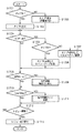
<Switching the review display (with face detection)>
FIG. 13 is a flowchart showing a flow of processing for switching the review display type and the focus area when the focus area is based on a face.
ステップS1301乃至S1307の処理により、デジタルカメラ100は、フラッシュメモリ25から取得したレビュータイプに応じたレビュー表示を行う。この時表示される顔画像や目画像は、評価値が最も高い合焦領域に関するものである。
Through the processing in steps S1301 to S1307, the
ステップS1308乃至S1315の処理により、デジタルカメラ100は、DISPスイッチ24が押下されると、レビュータイプを切り替える。そして、切り替え後のレビュータイプを、フラッシュメモリ25に格納する。
Through the processes in steps S1308 to S1315, the
ステップS1316及びS1317の処理により、デジタルカメラ100は、メニュースイッチ81が押下されると、評価値の高い順に、表示される顔画像や目画像に関連する合焦領域を順次切り替える(詳細は図14を参照して後述)。
Through the processing in steps S1316 and S1317, when the
ステップS1318及びS1319の処理により、デジタルカメラ100は、T/Wスイッチ21が押下されると、表示される顔画像や目画像のサイズを変更し、併せて全体画像のサイズも変更する(詳細は図15を参照して後述)。
By the processing in steps S1318 and S1319, when the T /
ステップS1320で、デジタルカメラ100は、レビュー表示が解除されたか否かを判定する。レビュー表示は、所定の時間が経過した場合や、レリーズスイッチ23の押下が解除された場合など、所定の条件に基づいて解除される。レビュー表示が解除されていなければ、ステップS1308に戻り、同様の処理を繰り返す。レビュー表示が解除されていれば、ステップS1321で、デジタルカメラ100は、レビュー表示を停止し、処理を終了する。
In step S1320, the
図14は、図13のステップS1317における処理の詳細な流れを示すフローチャートである。 FIG. 14 is a flowchart showing a detailed flow of the process in step S1317 of FIG.
ステップS1401に示すように、レビュー表示がタイプAの場合、顔画像や目画像は表示されないので、処理を終了する。 As shown in step S1401, when the review display is type A, the face image and the eye image are not displayed, and thus the process ends.
ステップS1402乃至S1408の処理により、デジタルカメラ100は、顔画像や目画像に関連する合焦領域を、評価値の順に基づいて切り替える。
Through the processes in steps S1402 to S1408, the
ステップS1409乃至S1413の処理により、デジタルカメラ100は、切り替え後の合焦領域に関連する顔画像や目画像を使用して、設定されているタイプのレビュー表示を行う。
Through the processing in steps S1409 to S1413, the
図15は、図13のステップS1319における処理の詳細な流れを示すフローチャートである。 FIG. 15 is a flowchart showing a detailed flow of the process in step S1319 of FIG.
ステップS1501及びS1506から理解できるように、タイプA又はタイプDの場合は、拡大画像のサイズは変更されず、処理は終了する。タイプAでは拡大画像が表示されず、タイプDでは、サイズを変更して表示することが困難だからである。もちろん、タイプDの場合、何らかの方法でサイズを変更可能にしても構わない。 As can be understood from steps S1501 and S1506, in the case of type A or type D, the size of the enlarged image is not changed, and the process ends. This is because an enlarged image is not displayed in type A, and it is difficult to change and display the size in type D. Of course, in the case of Type D, the size may be changed by some method.
ステップS1502乃至S1505の処理により、T/Wスイッチ21が押下されている間、デジタルカメラ100は、撮像画像から顔画像として抽出する領域のサイズを徐々に大きく又は小さくする。即ち、ステップS1004においては一例として、「顔のサイズが水平方向に約120%」になるサイズの領域を抽出したが、例えば、125%や115%のサイズの領域を抽出する。変更後のサイズは、フラッシュメモリ25に記憶される。フラッシュメモリ25に記憶された顔検出ありの場合の情報に基づいて次の撮像画像に対しては、当該領域が表示される。具体的には、例えば、顔画像のサイズ変更により顔領域の150%の領域が設定された場合には、次の撮像画像の際には、全体画像に対する顔領域の範囲が変わったとしても顔領域の150%の領域を表示するようにする。これによりユーザが所望する顔領域を次からは表示することができるようになる。
By the processing in steps S1502 to S1505, the
また、デジタルカメラ100は、モニタ51に表示する顔画像のサイズそのものを大きく又は小さくしても構わない。即ち、図9(b)では、表示される顔画像のサイズは120×160であったが、150×200に大きくなるなどしても構わない。このとき、表示される顔画像のサイズ変更に伴い、全体画像の表示可能サイズも変化するので、それに合わせた全体画像も生成される。
Further, the
ステップS1507乃至S1510の処理は、顔画像ではなく目画像に対して行われる点を除き、ステップS1502乃至S1505の処理と同様である。 The processing in steps S1507 to S1510 is the same as the processing in steps S1502 to S1505 except that the processing is performed on the eye image instead of the face image.
<レビュー表示(顔検出無)の概要>
図16は、撮像画像が図8に示されるものである場合の、図10のステップS1008におけるレビュー表示の概要を示す図である。
<Overview of review display (no face detection)>
FIG. 16 is a diagram showing an overview of the review display in step S1008 of FIG. 10 when the captured image is the one shown in FIG.
レビュー表示1601は、図9を参照して説明したタイプAに対応しており、レビュー表示1602及び1603は、図9を参照して説明したタイプEに対応している。最初は、デフォルトのタイプが表示される。タイプEのレビュー表示が行われる場合は、評価値が最も高い合焦領域に関する合焦位置画像が全体画像と併せて表示される。DISPスイッチ24が押下される度に、レビュー表示のタイプが切り替わり、メニュースイッチ81が押下される度に、合焦領域の評価値に従って、合焦位置画像が切り替わる。
The
<レビュー表示(顔検出無)の切り替え>
図17は、合焦領域が顔に基づくものでない場合に、レビュー表示のタイプ及び合焦領域を切り替える処理の流れを示すフローチャートである。
<Switching the review display (no face detection)>
FIG. 17 is a flowchart showing the flow of processing for switching the review display type and the focus area when the focus area is not based on the face.
ステップS1701乃至S1703の処理により、デジタルカメラ100は、フラッシュメモリ25から取得したレビュータイプに応じたレビュー表示を行う。この時表示される顔画像や目画像は、評価値が最も高い合焦領域に関するものである。
Through the processing in steps S1701 to S1703, the
ステップS1704乃至S1707の処理により、デジタルカメラ100は、DISPスイッチ24が押下されると、レビュータイプを切り替える。そして、切り替え後のレビュータイプを、フラッシュメモリ25に格納する。
Through the processing of steps S1704 to S1707, the
ステップS1708及びS1709の処理により、デジタルカメラ100は、メニュースイッチ81が押下されると、評価値の高い順に、表示される合焦位置画像に関連する合焦領域を順次切り替える(詳細は図18を参照して後述)。
By the processing of steps S1708 and S1709, when the
ステップS1710及びS1711の処理により、デジタルカメラ100は、T/Wスイッチ21が押下されると、表示される合焦位置画像のサイズを変更し、併せて全体画像のサイズも変更する(詳細は図19を参照して後述)。
Through the processing in steps S1710 and S1711, when the T /
ステップS1712で、デジタルカメラ100は、レビュー表示が解除されたか否かを判定する。レビュー表示は、所定の時間が経過した場合や、レリーズスイッチ23の押下が解除された場合など、所定の条件に基づいて解除される。レビュー表示が解除されていなければ、ステップS1704に戻り、同様の処理を繰り返す。レビュー表示が解除されていれば、ステップS1713で、デジタルカメラ100は、レビュー表示を停止し、処理を終了する。
In step S1712, the
図18は、図17のステップS1709における処理の詳細な流れを示すフローチャートである。 FIG. 18 is a flowchart showing a detailed flow of the process in step S1709 of FIG.
ステップS1801に示すように、レビュー表示がタイプAの場合、合焦位置画像は表示されないので、処理を終了する。 As shown in step S1801, when the review display is type A, since the focus position image is not displayed, the process ends.
ステップS1802乃至S1814の処理により、デジタルカメラ100は、合焦位置画像に関連する合焦領域を、評価値の順に基づいて切り替える。
Through the processes in steps S1802 to S1814, the
ステップS1815の処理により、デジタルカメラ100は、切り替え後の合焦領域に関連する合焦位置画像を使用して、設定されているタイプ(ここでは、タイプE)のレビュー表示を行う。
By the processing in step S1815, the
図19は、図17のステップS1711における処理の詳細な流れを示すフローチャートである。 FIG. 19 is a flowchart showing a detailed flow of the process in step S1711 of FIG.
ステップS1905タイプAの場合は、拡大画像のサイズは変更されず、処理は終了する。タイプAでは拡大画像が表示されないからである。 In the case of step S1905 type A, the size of the enlarged image is not changed, and the process ends. This is because type A does not display an enlarged image.
ステップS1902乃至S1905の処理により、T/Wスイッチ21が押下されている間、デジタルカメラ100は、合焦位置画像のサイズを徐々に大きく又は小さくする。変更後のサイズは、フラッシュメモリ25に記憶される。デジタルカメラ100は、各合焦領域について、変更後のサイズで合焦位置画像を生成する。また、合焦位置画像のサイズ変更に伴い、全体画像の表示可能サイズも変化するので、それに合わせた全体画像も生成する。
Through the processing in steps S1902 to S1905, the
ここで、ステップS1902における合焦位置画像のサイズ、図15のステップS1502における顔画像のサイズ、及び、S1507における目画像のサイズとは、それぞれ独立してフラッシュメモリ25に記憶される。ただし、例えばデフォルトのサイズからの補正率で合焦位置画像のサイズ等を表現し、1つの補正率を共用しても構わない。これにより、フラッシュメモリ25に記憶された顔検出なしの際の情報に基づいて次の撮像画像に対しては、当該領域が表示される。具体的には、例えば、合焦位置画像のサイズ変更により合焦位置領域の150%の領域が設定された場合には、次の撮像画像の際には、全体画像に対する合焦位置領域の範囲が変わったとしても合焦位置領域の150%の領域を表示するようにする。これによりユーザが所望する合焦位置領域を次からは表示することができるようになる。
Here, the size of the in-focus position image in step S1902, the size of the face image in step S1502 in FIG. 15, and the size of the eye image in step S1507 are stored in the
以上説明したように、本実施形態によれば、デジタルカメラ100は、撮像画像において合焦領域に関連する画像を拡大表示する際に、合焦領域が顔に関連するものであるか否かに応じて、異なる形式の拡大画像を表示する。
As described above, according to the present embodiment, when the
これにより、合焦領域が顔に関連して設定された焦点検出領域から選択されたものであるか否かに関わらず、撮像画像の合焦状態の確認に好適な拡大画像を画像表示装置に表示させることが可能となる。そのため、ユーザは、より容易に合焦状態を確認できるようになる。 Accordingly, an enlarged image suitable for confirming the in-focus state of the captured image is displayed on the image display device regardless of whether the in-focus area is selected from the focus detection areas set in relation to the face. It can be displayed. Therefore, the user can check the in-focus state more easily.
[その他の実施形態]
上述した実施の形態の処理は、各機能を具現化したソフトウェアのプログラムコードを記録した記憶媒体をシステム或は装置に提供してもよい。そして、そのシステム或は装置のコンピュータ(又はCPUやMPU)が記憶媒体に格納されたプログラムコードを読み出し実行することによって、前述した実施形態の機能を実現することができる。この場合、記憶媒体から読み出されたプログラムコード自体が前述した実施形態の機能を実現することになり、そのプログラムコードを記憶した記憶媒体は本発明を構成することになる。このようなプログラムコードを供給するための記憶媒体としては、例えば、フロッピィ(登録商標)ディスク、ハードディスク、光ディスク、光磁気ディスクなどを用いることができる。或いは、CD−ROM、CD−R、磁気テープ、不揮発性のメモリカード、ROMなどを用いることもできる。
[Other Embodiments]
In the processing of the above-described embodiment, a storage medium in which a program code of software that embodies each function is recorded may be provided to the system or apparatus. The functions of the above-described embodiments can be realized by the computer (or CPU or MPU) of the system or apparatus reading and executing the program code stored in the storage medium. In this case, the program code itself read from the storage medium realizes the functions of the above-described embodiments, and the storage medium storing the program code constitutes the present invention. As a storage medium for supplying such a program code, for example, a floppy (registered trademark) disk, a hard disk, an optical disk, a magneto-optical disk, or the like can be used. Alternatively, a CD-ROM, CD-R, magnetic tape, nonvolatile memory card, ROM, or the like can be used.
また、コンピュータが読み出したプログラムコードを実行することにより、前述した各実施の形態の機能が実現されるだけではない。そのプログラムコードの指示に基づき、コンピュータ上で稼動しているOS(オペレーティングシステム)などが実際の処理の一部又は全部を行い、その処理によって前述した各実施の形態の機能が実現される場合も含まれている。 The functions of the above-described embodiments are not only realized by executing the program code read by the computer. In some cases, an OS (operating system) running on the computer performs part or all of the actual processing based on the instruction of the program code, and the functions of the above-described embodiments are realized by the processing. include.
さらに、記憶媒体から読み出されたプログラムコードが、コンピュータに挿入された機能拡張ボードやコンピュータに接続された機能拡張ユニットに備わるメモリに書きこまれてもよい。その後、そのプログラムコードの指示に基づき、その機能拡張ボードや機能拡張ユニットに備わるCPUなどが実際の処理の一部又は全部を行い、その処理によって前述した各実施の形態の機能が実現される場合も含むものである。 Further, the program code read from the storage medium may be written in a memory provided in a function expansion board inserted into the computer or a function expansion unit connected to the computer. After that, the CPU of the function expansion board or function expansion unit performs part or all of the actual processing based on the instruction of the program code, and the functions of the above-described embodiments are realized by the processing. Is also included.
Claims (14)
前記焦点検出領域が撮像の際に検出された被写体の顔に基づいて決定されている場合、被写体の顔に関する情報に基づく、前記焦点検出領域とは異なる領域を撮像画像から抽出し、前記焦点検出領域が被写体の顔に基づいて決定されていない場合、前記焦点検出領域に一致する領域を撮像画像から抽出する抽出手段と、
前記抽出した領域の画像を表示部に表示する表示手段と、
を備えることを特徴とする画像表示装置。 An acquisition unit configured to acquire a captured image including the information about the focus detection area is used during an imaging,
When the focus detection area is determined based on the face of the subject detected at the time of imaging, an area different from the focus detection area based on information on the face of the subject is extracted from the captured image, and the focus detection An extraction means for extracting an area that matches the focus detection area from the captured image when the area is not determined based on the face of the subject ;
Display means for displaying an image of the extracted area on a display unit;
An image display device comprising:
取得した前記撮像画像の一部を表示部に表示する表示手段とを備え、
前記表示手段が、前記焦点検出領域が撮影の際に検出された被写体の顔の位置に対応して決定された場合は撮像画像に対して第1の割合の、前記焦点検出領域とは異なる領域を抽出して表示部に表示し、前記焦点検出領域が被写体の顔の位置に対応して決定されていない場合は前記焦点検出領域に一致する領域を抽出して表示部に表示することを特徴とする画像表示装置。 Acquisition means for acquiring a captured image captured is focusing on the basis of the output signal of the focus point detecting area,
Display means for displaying a part of the acquired captured image on a display unit;
When the display means determines the focus detection area corresponding to the position of the face of the subject detected at the time of shooting, an area different from the focus detection area in a first ratio with respect to the captured image displayed on the display unit extracts, said focus detection area is displayed on the display unit extracts an area that matches the focus detection area if it is not determined in accordance with the position of the face of the Utsushitai An image display device characterized by the above.
前記表示手段は、前記焦点検出領域が前記検出された被写体の顔に基づいて決定されている場合、前記焦点検出領域に対応する顔の一部又は全部を含む領域を前記第1の割合として前記表示部に表示することを特徴とする請求項2に記載の画像表示装置。 It said acquisition means further acquires information for specifying the position and size of the face of the detected subject,
When the focus detection area is determined based on the detected face of the subject, the display means sets, as the first ratio, an area including a part or all of the face corresponding to the focus detection area. The image display device according to claim 2, wherein the image display device displays the image on a display unit.
前記抽出手段は、前記焦点検出領域が前記検出された被写体の顔の位置に対応して決定されている場合、前記焦点検出領域に対応する顔の一部又は全部を含む複数の領域を抽出し、前記表示手段は、当該抽出した複数の領域の画像に加えて、前記撮像画像の全体を前記表示部に表示することを特徴とする請求項1又は2に記載の画像表示装置。 The acquisition means further acquires information capable of specifying the position and size of the detected face,
The extraction unit extracts a plurality of areas including a part or all of a face corresponding to the focus detection area when the focus detection area is determined corresponding to the position of the detected face of the subject. , the display means, in addition to the image of the plurality of areas the extracted image display apparatus according to claim 1 or 2 the whole of the captured image and displaying on the display unit.
撮像の際に使用された焦点検出領域に関する情報を含む撮像画像を取得する取得ステップと、
前記焦点検出領域が撮像の際に検出された被写体の顔に基づいて決定されている場合、被写体の顔に関する情報に基づく、前記焦点検出領域とは異なる領域を撮像画像から抽出し、前記焦点検出領域が被写体の顔に基づいて決定されていない場合、前記焦点検出領域に一致する領域を撮像画像から抽出する抽出ステップと、
前記抽出した領域の画像を表示部に表示する表示ステップと、
を備えることを特徴とする画像表示方法。 An image display method by an image processing apparatus,
An acquisition step of acquiring a captured image including the information about the focus detection area is used during an imaging,
If the previous SL focus detection area is determined based on the face of the detected subject during the imaging based on the information about the face of the object, extracted from the captured image a different region from that of the focus detection area, the focal point If the detection area is not determined based on the face of the subject, an extraction step of extracting an area that matches the focus detection area from the captured image ;
A display step of displaying an image before Symbol extracted area on the display unit,
An image display method comprising:
焦点検出領域の出力信号に基づいて焦点調節され撮像された撮像画像を取得する取得ステップと、
取得した前記撮像画像の一部を表示部に表示する表示ステップとを備え、
前記表示ステップにおいて、前記焦点検出領域が撮影の際に検出された被写体の顔の位置に対応して決定された場合は撮像画像に対して第1の割合の、前記焦点検出領域とは異なる領域を抽出して表示部に表示し、前記焦点検出領域が被写体の顔の位置に対応して決定されていない場合は前記焦点検出領域に一致する領域を抽出して表示部に表示することを特徴とする画像表示方法。 An image display method by an image processing apparatus,
An acquisition step of acquiring a captured image captured is focusing on the basis of the output signal of the focus point detecting area,
And a display step of displaying a portion of the acquisition was the captured image on the display unit,
Prior Symbol display step, the first rate with respect to the captured image if the focus detection area is determined in accordance with the position of the face of the detected subject during the shooting, different from the focus detection area displayed on the display unit by extracting an area, the focus detection area is displayed on the display unit extracts an area that matches the focus detection area if it is not determined in accordance with the position of the face of the Utsushitai An image display method characterized by the above.
Priority Applications (3)
| Application Number | Priority Date | Filing Date | Title |
|---|---|---|---|
| JP2006249958A JP4717766B2 (en) | 2006-09-14 | 2006-09-14 | Image display device, imaging device, image display method, storage medium, and program |
| US11/854,682 US8144234B2 (en) | 2006-09-14 | 2007-09-13 | Image display apparatus, image capturing apparatus, and image display method |
| CN2007101515043A CN101146179B (en) | 2006-09-14 | 2007-09-14 | Image display apparatus, image capturing apparatus, and image display method |
Applications Claiming Priority (1)
| Application Number | Priority Date | Filing Date | Title |
|---|---|---|---|
| JP2006249958A JP4717766B2 (en) | 2006-09-14 | 2006-09-14 | Image display device, imaging device, image display method, storage medium, and program |
Publications (3)
| Publication Number | Publication Date |
|---|---|
| JP2008072513A JP2008072513A (en) | 2008-03-27 |
| JP2008072513A5 JP2008072513A5 (en) | 2009-10-01 |
| JP4717766B2 true JP4717766B2 (en) | 2011-07-06 |
Family
ID=39188154
Family Applications (1)
| Application Number | Title | Priority Date | Filing Date |
|---|---|---|---|
| JP2006249958A Expired - Fee Related JP4717766B2 (en) | 2006-09-14 | 2006-09-14 | Image display device, imaging device, image display method, storage medium, and program |
Country Status (3)
| Country | Link |
|---|---|
| US (1) | US8144234B2 (en) |
| JP (1) | JP4717766B2 (en) |
| CN (1) | CN101146179B (en) |
Families Citing this family (50)
| Publication number | Priority date | Publication date | Assignee | Title |
|---|---|---|---|---|
| JP4961282B2 (en) * | 2007-07-03 | 2012-06-27 | キヤノン株式会社 | Display control apparatus and control method thereof |
| JP5053731B2 (en) * | 2007-07-03 | 2012-10-17 | キヤノン株式会社 | Image display control device, image display control method, program, and recording medium |
| JP5046788B2 (en) * | 2007-08-10 | 2012-10-10 | キヤノン株式会社 | Imaging apparatus and control method thereof |
| JP5173453B2 (en) * | 2008-01-22 | 2013-04-03 | キヤノン株式会社 | Imaging device and display control method of imaging device |
| JP5116514B2 (en) * | 2008-03-11 | 2013-01-09 | キヤノン株式会社 | Imaging apparatus and display control method |
| JP5036612B2 (en) * | 2008-03-28 | 2012-09-26 | 三洋電機株式会社 | Imaging device |
| JP5429445B2 (en) * | 2008-04-08 | 2014-02-26 | 富士フイルム株式会社 | Image processing system, image processing method, and program |
| RU2008113632A (en) * | 2008-04-10 | 2009-11-20 | Владимир Витальевич Мирошниченко (RU) | OBJECT HOLDING SYSTEM |
| US20090303338A1 (en) * | 2008-06-06 | 2009-12-10 | Texas Instruments Incorporated | Detailed display of portion of interest of areas represented by image frames of a video signal |
| CN101626458A (en) * | 2008-07-08 | 2010-01-13 | 鸿富锦精密工业(深圳)有限公司 | Photographic device and photographic method thereof |
| JP5171468B2 (en) * | 2008-08-06 | 2013-03-27 | キヤノン株式会社 | IMAGING DEVICE AND IMAGING DEVICE CONTROL METHOD |
| JP5223644B2 (en) | 2008-12-15 | 2013-06-26 | パナソニック株式会社 | Imaging device |
| US20100214445A1 (en) * | 2009-02-20 | 2010-08-26 | Sony Ericsson Mobile Communications Ab | Image capturing method, image capturing apparatus, and computer program |
| JP5361528B2 (en) * | 2009-05-15 | 2013-12-04 | キヤノン株式会社 | Imaging apparatus and program |
| US8036522B2 (en) * | 2009-06-04 | 2011-10-11 | Texas Instruments Incorporated | Method and system for auto-focusing |
| JP5430314B2 (en) * | 2009-09-18 | 2014-02-26 | キヤノン株式会社 | Imaging apparatus and control method thereof |
| FR2964203A1 (en) * | 2010-08-24 | 2012-03-02 | Franck Andre Marie Guigan | Image acquiring device e.g. camera, for use in photograph field of two-dimensional effects, has target determining unit determining part of panoramic, where viewing axis of device is passed through optical center of lens and sensor |
| JP5743514B2 (en) * | 2010-12-08 | 2015-07-01 | キヤノン株式会社 | Imaging apparatus, control method thereof, and program |
| JP6148431B2 (en) * | 2010-12-28 | 2017-06-14 | キヤノン株式会社 | Imaging apparatus and control method thereof |
| JP2012186670A (en) * | 2011-03-07 | 2012-09-27 | Ricoh Co Ltd | Imaging device, imaging method, and imaging program |
| WO2012164896A1 (en) * | 2011-05-31 | 2012-12-06 | パナソニック株式会社 | Image processing device, image processing method, and digital camera |
| US9041727B2 (en) | 2012-03-06 | 2015-05-26 | Apple Inc. | User interface tools for selectively applying effects to image |
| US9202433B2 (en) | 2012-03-06 | 2015-12-01 | Apple Inc. | Multi operation slider |
| US9131192B2 (en) | 2012-03-06 | 2015-09-08 | Apple Inc. | Unified slider control for modifying multiple image properties |
| US20130238747A1 (en) | 2012-03-06 | 2013-09-12 | Apple Inc. | Image beaming for a media editing application |
| JP2013191011A (en) * | 2012-03-14 | 2013-09-26 | Casio Comput Co Ltd | Image processing apparatus, image processing method and program |
| WO2013172566A1 (en) * | 2012-05-17 | 2013-11-21 | Lg Innotek Co., Ltd. | Camera module and method for auto focusing the same |
| US9277111B2 (en) * | 2012-05-18 | 2016-03-01 | Canon Kabushiki Kaisha | Image capture apparatus and control method therefor |
| US9064184B2 (en) | 2012-06-18 | 2015-06-23 | Ebay Inc. | Normalized images for item listings |
| CN102843514B (en) * | 2012-08-13 | 2016-09-21 | 东莞宇龙通信科技有限公司 | Photo shooting processing method and mobile terminal |
| US9690334B2 (en) | 2012-08-22 | 2017-06-27 | Intel Corporation | Adaptive visual output based on change in distance of a mobile device to a user |
| US9554049B2 (en) * | 2012-12-04 | 2017-01-24 | Ebay Inc. | Guided video capture for item listings |
| CN103888655B (en) * | 2012-12-21 | 2017-07-25 | 联想(北京)有限公司 | A kind of photographic method and electronic equipment |
| JP3182125U (en) * | 2012-12-26 | 2013-03-07 | オリンパスイメージング株式会社 | Imaging device |
| JP2014187551A (en) * | 2013-03-22 | 2014-10-02 | Casio Comput Co Ltd | Image acquisition device, image acquisition method and program |
| JP2015041150A (en) * | 2013-08-20 | 2015-03-02 | キヤノン株式会社 | Display control device and control method of the same |
| KR20150039355A (en) * | 2013-10-02 | 2015-04-10 | 엘지전자 주식회사 | Mobile terminal and control method thereof |
| JP2015105996A (en) * | 2013-11-29 | 2015-06-08 | ソニー株式会社 | Image processing apparatus, method, and program |
| CN103780819B (en) * | 2014-02-26 | 2017-05-24 | 深圳华用科技有限公司 | Intelligent industrial camera |
| WO2015129801A1 (en) * | 2014-02-26 | 2015-09-03 | 株式会社ニコン | Imaging apparatus |
| JP2016148732A (en) * | 2015-02-10 | 2016-08-18 | キヤノン株式会社 | Imaging device and image display method, program, and program storage medium |
| US10491828B2 (en) * | 2015-04-03 | 2019-11-26 | Canon Kabushiki Kaisha | Display control apparatus and control method of the same |
| KR102390809B1 (en) * | 2015-08-12 | 2022-04-26 | 삼성전자주식회사 | Method for providing image, electronic apparatus and storage medium |
| US10129477B2 (en) * | 2015-08-19 | 2018-11-13 | Google Llc | Smart image sensor having integrated memory and processor |
| CN106454089A (en) * | 2016-10-08 | 2017-02-22 | 广东小天才科技有限公司 | Photographing reminding method and device for camera |
| US10497122B2 (en) | 2017-10-11 | 2019-12-03 | Adobe Inc. | Image crop suggestion and evaluation using deep-learning |
| US10516830B2 (en) * | 2017-10-11 | 2019-12-24 | Adobe Inc. | Guided image composition on mobile devices |
| JP2020092315A (en) * | 2018-12-04 | 2020-06-11 | キヤノン株式会社 | Display control device, imaging apparatus, display device control method, program, and storage medium |
| JP7364381B2 (en) * | 2019-07-19 | 2023-10-18 | ファナック株式会社 | Image processing device |
| CN111263066B (en) * | 2020-02-18 | 2021-07-20 | Oppo广东移动通信有限公司 | Composition guiding method, composition guiding device, electronic equipment and storage medium |
Citations (4)
| Publication number | Priority date | Publication date | Assignee | Title |
|---|---|---|---|---|
| JP2003153045A (en) * | 2001-11-19 | 2003-05-23 | Olympus Optical Co Ltd | Camera |
| JP2003179798A (en) * | 2001-12-10 | 2003-06-27 | Canon I-Tech Inc | Digital camera |
| JP2005091432A (en) * | 2003-09-12 | 2005-04-07 | Olympus Corp | Camera |
| JP2005102175A (en) * | 2003-08-25 | 2005-04-14 | Fuji Photo Film Co Ltd | Digital camera |
Family Cites Families (10)
| Publication number | Priority date | Publication date | Assignee | Title |
|---|---|---|---|---|
| JP2001211351A (en) * | 2000-01-27 | 2001-08-03 | Fuji Photo Film Co Ltd | Image pickup device and its operation control method |
| JP4794786B2 (en) | 2001-09-28 | 2011-10-19 | 株式会社リコー | Imaging apparatus, automatic exposure method, and program for computer to execute the method |
| JP2003107335A (en) | 2001-09-28 | 2003-04-09 | Ricoh Co Ltd | Image pickup device, automatic focusing method, and program for making computer execute the method |
| US7298412B2 (en) * | 2001-09-18 | 2007-11-20 | Ricoh Company, Limited | Image pickup device, automatic focusing method, automatic exposure method, electronic flash control method and computer program |
| JP2004064259A (en) | 2002-07-26 | 2004-02-26 | Kyocera Corp | System for confirming focus of digital camera |
| GB2395779A (en) * | 2002-11-29 | 2004-06-02 | Sony Uk Ltd | Face detection |
| US7453506B2 (en) * | 2003-08-25 | 2008-11-18 | Fujifilm Corporation | Digital camera having a specified portion preview section |
| JP4489608B2 (en) * | 2004-03-31 | 2010-06-23 | 富士フイルム株式会社 | DIGITAL STILL CAMERA, IMAGE REPRODUCTION DEVICE, FACE IMAGE DISPLAY DEVICE, AND CONTROL METHOD THEREOF |
| JP4352980B2 (en) | 2004-04-23 | 2009-10-28 | オムロン株式会社 | Enlarged display device and enlarged image control device |
| JP4674471B2 (en) | 2005-01-18 | 2011-04-20 | 株式会社ニコン | Digital camera |
-
2006
- 2006-09-14 JP JP2006249958A patent/JP4717766B2/en not_active Expired - Fee Related
-
2007
- 2007-09-13 US US11/854,682 patent/US8144234B2/en not_active Expired - Fee Related
- 2007-09-14 CN CN2007101515043A patent/CN101146179B/en not_active Expired - Fee Related
Patent Citations (4)
| Publication number | Priority date | Publication date | Assignee | Title |
|---|---|---|---|---|
| JP2003153045A (en) * | 2001-11-19 | 2003-05-23 | Olympus Optical Co Ltd | Camera |
| JP2003179798A (en) * | 2001-12-10 | 2003-06-27 | Canon I-Tech Inc | Digital camera |
| JP2005102175A (en) * | 2003-08-25 | 2005-04-14 | Fuji Photo Film Co Ltd | Digital camera |
| JP2005091432A (en) * | 2003-09-12 | 2005-04-07 | Olympus Corp | Camera |
Also Published As
| Publication number | Publication date |
|---|---|
| US8144234B2 (en) | 2012-03-27 |
| CN101146179A (en) | 2008-03-19 |
| JP2008072513A (en) | 2008-03-27 |
| US20080068487A1 (en) | 2008-03-20 |
| CN101146179B (en) | 2010-06-02 |
Similar Documents
| Publication | Publication Date | Title |
|---|---|---|
| JP4717766B2 (en) | Image display device, imaging device, image display method, storage medium, and program | |
| JP5381060B2 (en) | Imaging apparatus and image processing method thereof | |
| KR101889932B1 (en) | Apparatus and Method for photographing image | |
| CN100508558C (en) | Image-capturing device, image-processing device, method for controlling image-capturing device, and program for causing computer to execute the method | |
| JP2013013050A (en) | Imaging apparatus and display method using imaging apparatus | |
| CN102075683A (en) | Digital image processing apparatus and photographing method of digital image processing apparatus | |
| US20130135428A1 (en) | Method of providing panoramic image and imaging device thereof | |
| EP2587407A1 (en) | Vision recognition apparatus and method | |
| US20120063759A1 (en) | Automatic focusing apparatus | |
| US9420162B2 (en) | Image capturing apparatus and control method thereof | |
| JP2009124340A (en) | Imaging apparatus, photographing support method, and photographing support program | |
| US9445085B2 (en) | Imaging apparatus, method for controlling imaging apparatus, and system therefor | |
| JP5849389B2 (en) | Imaging apparatus and imaging method | |
| KR20130060040A (en) | Method for providing user interface and image photographing apparatus thereof | |
| KR20130015422A (en) | Method for providing reference image and image photographing device thereof | |
| JP4647518B2 (en) | Imaging device | |
| JP4759775B2 (en) | Image recording method and apparatus | |
| EP3672218B1 (en) | Imaging apparatus | |
| JP5915720B2 (en) | Imaging device | |
| JP2010050599A (en) | Electronic camera | |
| JP5625325B2 (en) | Image data recording apparatus and image data recording program | |
| JP5417920B2 (en) | Image processing apparatus, image processing method, electronic camera, and image processing program | |
| JP2011109548A (en) | Imaging apparatus | |
| JP4986588B2 (en) | Imaging apparatus and control method thereof | |
| JP2009296143A (en) | Imaging device |
Legal Events
| Date | Code | Title | Description |
|---|---|---|---|
| A521 | Request for written amendment filed |
Free format text: JAPANESE INTERMEDIATE CODE: A523 Effective date: 20090818 |
|
| A621 | Written request for application examination |
Free format text: JAPANESE INTERMEDIATE CODE: A621 Effective date: 20090818 |
|
| A977 | Report on retrieval |
Free format text: JAPANESE INTERMEDIATE CODE: A971007 Effective date: 20101210 |
|
| A131 | Notification of reasons for refusal |
Free format text: JAPANESE INTERMEDIATE CODE: A131 Effective date: 20101217 |
|
| A521 | Request for written amendment filed |
Free format text: JAPANESE INTERMEDIATE CODE: A523 Effective date: 20110207 |
|
| TRDD | Decision of grant or rejection written | ||
| A01 | Written decision to grant a patent or to grant a registration (utility model) |
Free format text: JAPANESE INTERMEDIATE CODE: A01 Effective date: 20110325 |
|
| A01 | Written decision to grant a patent or to grant a registration (utility model) |
Free format text: JAPANESE INTERMEDIATE CODE: A01 |
|
| A61 | First payment of annual fees (during grant procedure) |
Free format text: JAPANESE INTERMEDIATE CODE: A61 Effective date: 20110330 |
|
| R150 | Certificate of patent or registration of utility model |
Free format text: JAPANESE INTERMEDIATE CODE: R150 |
|
| FPAY | Renewal fee payment (event date is renewal date of database) |
Free format text: PAYMENT UNTIL: 20140408 Year of fee payment: 3 |
|
| LAPS | Cancellation because of no payment of annual fees |