JP4717539B2 - Imaging apparatus and imaging method - Google Patents
Imaging apparatus and imaging method Download PDFInfo
- Publication number
- JP4717539B2 JP4717539B2 JP2005215981A JP2005215981A JP4717539B2 JP 4717539 B2 JP4717539 B2 JP 4717539B2 JP 2005215981 A JP2005215981 A JP 2005215981A JP 2005215981 A JP2005215981 A JP 2005215981A JP 4717539 B2 JP4717539 B2 JP 4717539B2
- Authority
- JP
- Japan
- Prior art keywords
- image data
- buffer memory
- recording
- stored
- image
- Prior art date
- Legal status (The legal status is an assumption and is not a legal conclusion. Google has not performed a legal analysis and makes no representation as to the accuracy of the status listed.)
- Active
Links
Images


Description
本発明は、動画と静止画とを同時に撮影する撮像技術に関する。 The present invention relates to an imaging technique for simultaneously capturing a moving image and a still image.
従来より、動画と動画よりも高画素、高画質な静止画とを切り替えて撮影可能なハイブリッドカメラが知られている。 Conventionally, a hybrid camera capable of shooting by switching between a moving image and a still image having higher pixels and higher image quality than the moving image is known.
動画などを低画素で記録中に高画素の静止画を記録することを可能としたものとして、例えば特許文献1に記載されたようにモードボタンを押下することにより高画素静止画の記録を行うものがある(図11)。
For example, as described in
また、特許文献2に記載されたように無線通信により外部から撮影モードを高画質モードに切り替えるものが知られている(図12)。図11ではS1010でシャッターボタンを押下することにより、図13の通常の動画フレーム(図13では320x240画素)で記録を行う。S1014で高画質モードボタンが押下されることにより図13の高画素記録したフレーム(図中で1280x960画素)を動画フレーム中に挿入する。また、図12では、受信手段103、アンテナ106,111、送信手段110からなる無線通信手段を介して、外部コントローラ107が撮像装置101の記録モード制御手段104及び撮影制御手段105を制御して高速撮影と高画質撮影とを切り替える。
Further, as described in Patent Document 2, there is known one that switches a photographing mode from the outside to a high image quality mode by wireless communication (FIG. 12). In FIG. 11, by pressing the shutter button in S1010, recording is performed with the normal moving image frame (320 × 240 pixels in FIG. 13) in FIG. When the high image quality mode button is pressed in S1014, the frame (1280 × 960 pixels in the drawing) recorded in FIG. 13 is inserted into the moving image frame. In FIG. 12, the
更に望ましい撮影を行うためのシャッターチャンスを判別するものとして、特許文献3に記載されたように、被写体が望ましい表情やポーズになったときにカメラが自動的にシャッターチャンスを判別して撮影を行う方法が提案されている(図14)。図14の例では画像を撮像部202で繰り返し取得し、制御部209が予め設定された条件を満たしたと判定した場合、撮像部202のフォーカスや絞りを制御して撮影を行う。なお、シャッターチャンスの判別は、人物の表情などを表わす形状を画像から抽出し、この抽出された形状と所定の形状の一致度を算出して、一致度が所定値を超えたときに被写体を撮影するためのシャッターチャンスと判別する。
動画撮影中に出会う一瞬の表情などのシャッターチャンスを、動画の記録に影響を与えないで高画質で記録しておきたいという要求がある。これに対して、上記特許文献1,2では、動画撮影中に高画素な静止画撮影に切り替えることができるので、動画撮影を行いながらシャッターチャンスを待って望ましい静止画を撮影することが可能となる。
There is a demand to record shutter chances such as momentary facial expressions encountered during movie shooting with high image quality without affecting movie recording. On the other hand, in
しかしながら、動画撮影モードから高画質撮影モードに切り替えるときにタイムラグが生じることで、ユーザがシャッターボタンを押下する際にシャッターチャンスを逃してしまうおそれがある。その結果、一瞬の瞬きによる目瞑り画像を防いだり、笑顔などの良い表情の瞬間を捕らえるには予め変化を予測してシャッターを切るなどの高度なテクニックが必要となるため、失敗撮影となってしまう可能性も高い。また、上記特許文献2では高画質撮影のために動画撮影が中断されてしまうため動画の記録が長時間途切れてしまう。 However, a time lag occurs when switching from the moving image shooting mode to the high image quality shooting mode, which may cause the user to miss a photo opportunity when the user presses the shutter button. As a result, advanced techniques, such as predicting changes in advance and releasing the shutter, are necessary to prevent eye-meditation images caused by a momentary blink or capture a moment with a good facial expression such as a smile. There is a high possibility that it will end. Also, in the above-mentioned Patent Document 2, moving image shooting is interrupted for high image quality shooting, and therefore moving image recording is interrupted for a long time.
上記特許文献3では、カメラがシャッターチャンスを自動で判別するため、ユーザ自身がシャッターチャンスのトリガを捕らえる必要はなくなる。但し、過去に撮影した画像から次のシャッターチャンスを判別して撮影動作に移るため、やはりAFや絞りなどの動作や、フレーム間の時間差などのタイムラグがあり一瞬のシャッターチャンスを逃してしまうおそれが残る。また、撮像部202が静止画の撮像のために占有されてしまうため動画を同時に撮影することも不可能である。
In Patent Document 3, since the camera automatically determines the photo opportunity, the user does not need to capture the photo opportunity trigger. However, since the next photo opportunity is determined from the image taken in the past and the operation is shifted to the image taking operation, there is still a time lag such as an AF or aperture operation or a time difference between frames, and there is a possibility that a momentary photo opportunity may be missed. Remain. In addition, since the
また、動画撮影系と、表情などの顔検出系を含む高画質撮影系とを別の光学系とし、一つの筐体に搭載した2眼構成も考えられる。しかし装置が大掛かりであり、2つの光学系を同期して制御する難しさがある。更に画角、フォーカス状況、絞り開度などが2つの光学系で必ずしも一致しないため意図した画像が得られない可能性が高い。 In addition, a two-lens configuration in which a moving image shooting system and a high-quality shooting system including a face detection system such as a facial expression are separate optical systems and mounted in one housing is also conceivable. However, the apparatus is large and there is a difficulty in controlling the two optical systems in synchronization. Furthermore, since the angle of view, the focus state, the aperture opening degree, and the like do not necessarily match in the two optical systems, there is a high possibility that the intended image cannot be obtained.
本発明は、上記課題を解決することを目的としている。 The present invention aims to solve the above problems.
上記課題を解決し、目的を達成するために、本発明の撮像装置は、撮像素子にて生成された動画の画像データを取り込んで、第2のバッファメモリに第2の画像データとして記憶させ、前記第2の画像データの予め定められたフレームと同じタイミングで前記撮像素子にて生成された画像データを取り込んで、第1のバッファメモリに第1の画像データとして記憶させる撮像手段と、前記第2の画像データを用いて被写体が所定の条件を満たしているか分析する分析手段と、前記第1のバッファメモリに記憶された前記第1の画像データを第1の記録手段に記録し、前記第2のバッファメモリに記憶された前記第2の画像データを第2の記録手段に記録する記録制御手段とを有し、前記第1の画像データは前記第2の画像データと比較して高解像度及び多階調の少なくともいずれかであって、前記記録制御手段は、前記分析手段がいずれかのフレームの前記第2の画像データを用いて分析を行った結果、被写体が前記所定の条件を満たしていれば、前記いずれかのフレームの前記第2の画像データと同じタイミングで取り込まれて前記第1のバッファメモリに記憶された前記第1の画像データを前記第1の記録手段へ記録し、被写体が前記所定の条件を満たしていなければ、前記いずれかのフレームの前記第2の画像データと同じタイミングで取り込まれて前記第1のバッファメモリに記憶された前記第1の画像データを前記第1の記録手段へ記録しない。
本発明の撮像装置は、撮像素子にて生成された連続する画像データを取り込んで、第2のバッファメモリに第2の画像データとして記憶させ、前記第2の画像データの予め定められたフレームと同じタイミングで前記撮像素子にて生成された画像データを取り込んで、第1のバッファメモリに第1の画像データとして記憶させる撮像手段と、前記第2の画像データを用いて被写体が所定の条件を満たしているか分析する分析手段と、前記第1のバッファメモリに記憶された前記第1の画像データを第1の記録手段に記録し、前記第2のバッファメモリに記憶された前記第2の画像データを第2の記録手段に記録する記録制御手段と、いずれかのフレームの前記第2の画像データが前記所定の条件を満たすときにその旨を通知する通知手段と、前記通知手段による通知の後に、前記所定の条件を満たす前記いずれかのフレームの第2の画像データと同じタイミングで取り込まれて前記第1のバッファメモリに記憶された第1の画像データを前記第1の記録手段に記録するか否かを選択させる選択手段とを有し、前記第1の画像データは前記第2の画像データと比較して高解像度及び多階調の少なくともいずれかであって、前記記録制御手段は、前記選択手段により前記第1の画像データを記録することが選択されれば、前記いずれかのフレームの前記第2の画像データと同じタイミングで取り込まれて前記第1のバッファメモリに記憶された前記第1の画像データを前記第1の記録手段へ記録し、前記選択手段により前記第1の画像データを記録することが選択されなければ、前記いずれかのフレームの前記第2の画像データと同じタイミングで取り込まれて前記第1のバッファメモリに記憶された前記第1の画像データを前記第1の記録手段へ記録しない。
In order to solve the above-described problems and achieve the object, the imaging apparatus of the present invention takes in image data of a moving image generated by the imaging element and stores it as second image data in a second buffer memory. Image capturing means for capturing image data generated by the image sensor at the same timing as a predetermined frame of the second image data, and storing the image data as first image data in a first buffer memory; Analysis means for analyzing whether or not a subject satisfies a predetermined condition using the second image data, and the first image data stored in the first buffer memory is recorded in a first recording means, the second image data stored in the second buffer memory and a recording control means for recording in the second recording means, the first image data is higher compared to the second image data Zodo and be at least one of multi-tone, the recording control means as a result of said analyzing means were analyzed using the second image data of one frame, the subject is said predetermined condition If the above condition is satisfied, the first image data captured at the same timing as the second image data of any one of the frames and stored in the first buffer memory is recorded in the first recording unit . If the subject does not satisfy the predetermined condition, the first image data captured at the same timing as the second image data of any one of the frames and stored in the first buffer memory is stored. Recording is not performed on the first recording means .
The image pickup apparatus of the present invention captures continuous image data generated by the image pickup device and stores it as second image data in a second buffer memory, and a predetermined frame of the second image data; Image capturing means that captures image data generated by the image sensor at the same timing and stores the image data as first image data in a first buffer memory, and the subject satisfies a predetermined condition using the second image data. Analyzing means for analyzing whether it is satisfied, the first image data stored in the first buffer memory is recorded in the first recording means, and the second image stored in the second buffer memory a recording control means for recording the data in the second recording means, and notifying means for said second image data of one frame notifies when the predetermined condition is satisfied, After notification by serial notifying means, wherein the first image data that has been captured and stored in the first buffer memory at the same timing as the second image data of the predetermined condition is satisfied said one frame No. and a selection means for selecting whether to record the first recording means, the first image data is a at least one high resolution and multi-tone in comparison with the second image data The recording control means is fetched at the same timing as the second image data of any one of the frames if the selection means selects to record the first image data . the first image data stored in the buffer memory is recorded to the first recording means, if it is selected for recording the first image data by said selecting means, said doctor Not recording the first image data stored in the first buffer memory to said first recording means incorporated at the same timing as the second image data of Re or of the frame.
また、本発明の撮像方法は、撮像素子にて生成された動画の画像データを取り込んで、第2のバッファメモリに第2の画像データとして記憶させ、前記第2の画像データの予め定められたフレームと同じタイミングで前記撮像素子にて生成された画像データを取り込んで、第1のバッファメモリに第1の画像データとして記憶させる撮像工程と、前記第2の画像データを用いて被写体が所定の条件を満たしているか分析する分析工程と、前記第1のバッファメモリに記憶された前記第1の画像データを第1の記録手段に記録し、前記第2のバッファメモリに記憶された前記第2の画像データを第2の記録手段に記録する記録制御工程とを有し、前記第1の画像データは前記第2の画像データと比較して高解像度及び多階調の少なくともいずれかであって、前記記録制御工程では、前記分析工程にていずれかのフレームの前記第2の画像データを用いて分析を行った結果、被写体が前記所定の条件を満たしていれば、前記いずれかのフレームの前記第2の画像データと同じタイミングで取り込まれて前記第1のバッファメモリに記憶された前記第1の画像データを前記第1の記録手段へ記録し、被写体が前記所定の条件を満たしていなければ、前記いずれかのフレームの前記第2の画像データと同じタイミングで取り込まれて前記第1のバッファメモリに記憶された前記第1の画像データを前記第1の記録手段へ記録しない。
本発明の撮像方法は、撮像素子にて生成された連続する画像データを取り込んで、第2のバッファメモリに第2の画像データとして記憶させ、前記第2の画像データの予め定められたフレームと同じタイミングで前記撮像素子にて生成された画像データを取り込んで、第1のバッファメモリに第1の画像データとして記憶させる撮像工程と、前記第2の画像データを用いて被写体が所定の条件を満たしているか分析する分析工程と、前記第1のバッファメモリに記憶された前記第1の画像データを第1の記録手段に記録し、前記第2のバッファメモリに記憶された前記第2の画像データを第2の記録手段に記録する記録制御工程と、いずれかのフレームの前記第2の画像データが前記所定の条件を満たすときにその旨を通知する通知工程と、前記通知工程による通知の後に、前記所定の条件を満たす前記いずれかのフレームの第2の画像データと同じタイミングで取り込まれて前記第1のバッファメモリに記憶された第1の画像データを前記第1の記録手段に記録するか否かを選択させる選択工程とを有し、前記第1の画像データは前記第2の画像データと比較して高解像度及び多階調の少なくともいずれかであって、前記記録制御工程では、前記選択工程により前記第1の画像データを記録することが選択されれば、前記いずれかのフレームの前記第2の画像データと同じタイミングで取り込まれて前記第1のバッファメモリに記憶された前記第1の画像データを前記第1の記録手段へ記録し、前記選択工程により前記第1の画像データを記録することが選択されなければ、前記いずれかのフレームの前記第2の画像データと同じタイミングで取り込まれて前記第1のバッファメモリに記憶された前記第1の画像データを前記第1の記録手段へ記録しない。
In addition, the image pickup method of the present invention takes in image data of a moving image generated by the image pickup device and stores it as second image data in a second buffer memory, and the second image data is predetermined. An image capturing process that captures image data generated by the image sensor at the same timing as a frame and stores the image data as first image data in a first buffer memory ; An analysis step for analyzing whether the condition is satisfied, the first image data stored in the first buffer memory is recorded in a first recording means, and the second image stored in the second buffer memory and a recording control step of the image data recorded in the second recording means, the first image data is high-resolution and any grayscale least compared to the second image data A is, the recording control step, the analysis result of the analysis using the second image data of one frame in step, if the object is to meet the predetermined condition, the one The first image data captured at the same timing as the second image data of the frame and stored in the first buffer memory is recorded in the first recording means , and the subject satisfies the predetermined condition. If not , the first image data captured at the same timing as the second image data of any one of the frames and stored in the first buffer memory is not recorded in the first recording means . .
According to the imaging method of the present invention, continuous image data generated by an imaging device is captured and stored as second image data in a second buffer memory, and a predetermined frame of the second image data is stored. An image capturing process that captures image data generated by the image sensor at the same timing and stores the image data as first image data in a first buffer memory; and the subject uses the second image data to satisfy a predetermined condition. An analysis step for analyzing whether the image is satisfied, and the first image data stored in the first buffer memory is recorded in a first recording means, and the second image stored in the second buffer memory a recording control step of recording the data in the second recording means, and a notification step of the second image data of one frame notifies when the predetermined condition is satisfied, After notification by serial notification step, wherein the first image data that has been captured and stored in the first buffer memory at the same timing as the second image data of the predetermined condition is satisfied said one frame No. and a selection step of selecting whether to record the first recording means, the first image data is a at least one high resolution and multi-tone in comparison with the second image data In the recording control step, if recording the first image data is selected in the selection step, the first image data is captured at the same timing as the second image data in any one of the frames. the first image data stored in the buffer memory is recorded to the first recording means, if it is selected for recording the first image data by said selecting step, said The first image data stored in the first buffer memory is incorporated at the same timing as the second image data of a frame of Zureka not recorded to the first recording means.
本発明によれば、連続して撮影される動画と高画質な静止画とを同時に撮影でき、動画撮影に影響を及ぼさず且つシャッターチャンスを逃さずに高画質な静止画を撮影することができる。 According to the present invention, it is possible to shoot a continuously shot moving image and a high-quality still image at the same time, and to shoot a high-quality still image without affecting the moving image shooting and without missing a photo opportunity. .
以下に、添付図面を参照して本発明を実施するための最良の形態について詳細に説明する。 The best mode for carrying out the present invention will be described below in detail with reference to the accompanying drawings.
尚、以下に説明する実施の形態は、本発明の実現手段としての一例であり、本発明が適用される装置の構成や各種条件によって適宜修正又は変更されるべきものであり、本発明は以下の実施の形態に限定されるものではない。
[第1の実施形態]
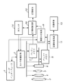
図1は本発明に係る実施形態の撮像装置の構成を示すブロック図である。図2は図1の撮像装置による動作フローチャートを示す。
The embodiment described below is an example as means for realizing the present invention, and should be appropriately modified or changed according to the configuration and various conditions of the apparatus to which the present invention is applied. It is not limited to the embodiment.
[First Embodiment]
FIG. 1 is a block diagram illustrating a configuration of an imaging apparatus according to an embodiment of the present invention. FIG. 2 shows an operation flowchart of the imaging apparatus of FIG.
図1において、1はユーザインターフェースである。1ではカメラの画角やオートフォーカスなどの光学系3及びズーム4の調整指示、絞り5の調整指示、録画(連続画像の取り込み)開始終了指令、撮影条件や画像条件の指定(例えば、笑顔や目瞑り防止など)などを行うことができる。2はカメラ制御回路で光学系3やズーム4からなるズーム制御やオートフォーカス制御、絞り5の駆動、CCDなどの撮像素子6からバッファメモリ7,8への電荷信号の転送駆動、連続画像の記録制御回路10,11の制御などを行う。
In FIG. 1, 1 is a user interface. 1, an adjustment instruction for the optical system 3 and zoom 4 such as the camera angle of view and autofocus, an adjustment instruction for the aperture 5, a recording (continuous image capturing) start / end instruction, a shooting condition and an image condition specification (for example, smile, Etc.). Reference numeral 2 denotes a camera control circuit. Zoom control and autofocus control including the optical system 3 and zoom 4, driving of the diaphragm 5, transfer of charge signals from the image sensor 6 such as a CCD to the buffer memories 7 and 8, and continuous image recording Control of the
7,8はバッファメモリである。バッファメモリ8はカメラ制御回路2の録画開始指令により画像を所定のレート(例えば、1フレーム30msec)で連続的に取り込む所定の解像度で画像を取り込むバッファメモリである。バッファメモリ7はバッファメモリ8より高解像度又は多階調又はその両方である高画質バッファメモリであり、カメラ制御回路2から出される所定のトリガ信号により1フレーム分を取り込む。 Reference numerals 7 and 8 denote buffer memories. The buffer memory 8 is a buffer memory that captures images at a predetermined resolution that continuously captures images at a predetermined rate (for example, 30 msec per frame) in response to a recording start command from the camera control circuit 2. The buffer memory 7 is a high-quality buffer memory having higher resolution and / or multiple gradations than the buffer memory 8, and takes in one frame by a predetermined trigger signal output from the camera control circuit 2.
画像分析回路9はバッファメモリ8の内容を解析して、所定の撮影条件や画像条件(例えば、笑顔や目瞑り防止など)に合致しているときに記録信号を記録制御回路10に出力する。10,11は記録制御回路である。記録制御回路11はカメラ制御回路2の録画開始指令により所定のレート(例えば、1フレーム30msec)でバッファメモリ8に蓄えられている画像データを記録媒体13に記録する。
The
記録制御回路10は画像分析回路9からの記録信号が入力されたときのみバッファメモリ7にその時点で記憶されている1フレームの画像データを記録媒体12に記録する。記録媒体12,13は画像データを長期保存するための記憶媒体で磁気テープや光ディスク、半導体メモリ(フラッシュROMなど)が該当する。図1では記録媒体は2つとされているが、ランダムアクセス可能かつ2箇所に独立して別のデータを書き込めるメモリの場合は1つでよい。また、ランダムアクセス可能かつ十分に高速である場合も、時分割書き込みを行えば1つでよい。
The
次に、図1の撮像装置の動作について図2のフローチャートを用いて説明する。 Next, the operation of the imaging apparatus of FIG. 1 will be described using the flowchart of FIG.
撮像装置の電源がONされると、所望の条件(笑顔や目瞑り防止など)がユーザ操作などによって設定される(S101)。このときに同時に所望の画像の取得枚数も設定される。なお、所望の条件が設定されていて画像枚数が設定されていないとき、又は記録媒体12に記憶可能な枚数よりも多く設定されたときには記録媒体12に記憶可能な枚数を指定枚数としてもよい。この時に確認を促す警告をユーザインターフェース1に出力することも可能である。
When the power supply of the imaging apparatus is turned on, desired conditions (such as smiles and prevention of eye meditation) are set by a user operation or the like (S101). At this time, the desired number of acquired images is also set. Note that when the desired condition is set and the number of images is not set, or when the number of images that can be stored in the
その後、ビデオ録画するかどうかが判定される(S102)。ここでは、通常はユーザによって録画ボタンが押されるか、外部機器より録画信号が入力されたかを判断する。ビデオ録画開始が検出されるとカメラ制御回路2は撮像素子6で撮像した画像データを所定の解像度、更新レートでバッファメモリ8に取り込み(S103)、記録媒体13への記録を順次行う(S107)。 Thereafter, it is determined whether to record a video (S102). Here, it is usually determined whether the recording button is pressed by the user or a recording signal is input from an external device. When the start of video recording is detected, the camera control circuit 2 captures image data captured by the image sensor 6 into the buffer memory 8 at a predetermined resolution and update rate (S103), and sequentially records on the recording medium 13 (S107). .
また、S103でフレームを取り込むのと同時刻に、高画質(高画素、多階調、或いはその両方)の画像データをバッファメモリ7に取り込み保持する(S104)。ここで一旦保持されると記録信号又は破棄信号が入力されるまでバッファメモリ8が更新されても、バッファメモリ7の内容は保持される。バッファメモリ7に取り込まれた時刻と同時刻のバッファメモリ8の内容は画像分析回路9に転送され、ユーザが指定した条件(笑顔など)に沿った条件解析検出処理が行われる(S105)。更に、S105での検出結果と指定条件とが合致しているかを判定する(S106)。ここでは、カウンタ14に記録された枚数を元に記録枚数は指定枚数以下かが判定され、それらを満たしているときには記録信号が記録制御回路10に出力され、バッファメモリ7の内容が記録媒体12に書き込まれ、カウンタ14がインクリメントされる。また、S105での検出結果と合致しないときは、廃棄信号がカメラ制御回路2に出力され、次のバッファメモリ8の取り込みタイミングでバッファメモリ7も更新される。
In addition, at the same time as capturing the frame in S103, image data with high image quality (high pixels, multiple gradations, or both) is captured and held in the buffer memory 7 (S104). Once held, even if the buffer memory 8 is updated until a recording signal or a discard signal is input, the contents of the buffer memory 7 are held. The contents of the buffer memory 8 at the same time as the time taken into the buffer memory 7 are transferred to the
以上の動作をタイムチャートで示したのが図3である。ここでVrateはビデオレートで、この周波数で連続画像の更新が行われる。図3ではt0,t1,t2で連続画像データと高画質画像データが同時にバッファメモリ7,8に取り込まれ、連続画像データを用いて分析が行われる。一般には高画質画像の方がデータ量が多いので処理時間がかかる。この例では高画質画像データの記録媒体への記録までに連続画像データの2フレーム分が使われる例を示した。 FIG. 3 shows the above operation in a time chart. Here, Vrate is a video rate, and continuous images are updated at this frequency. In FIG. 3, continuous image data and high-quality image data are simultaneously fetched into the buffer memories 7 and 8 at t0, t1, and t2, and analysis is performed using the continuous image data. In general, a high-quality image requires more processing time because it has a larger amount of data. In this example, two frames of continuous image data are used before recording high-quality image data on a recording medium.
なお、バッファメモリ7に取り込まれた高画質画像データは常に記録媒体に記録するわけでない。このため、書き込み用のバッファメモリを用意して画像データを一時蓄積しておいて、画像データを保存しないときなどにバッファメモリ分の書き込みを行ことで、時間あたりの書き込み頻度を増すことができる。また、高画質画像データ取り込み用に複数のバッファメモリを用意し、それと同数の条件解析検出用バッファメモリを用意しておくこともできる。この場合には、連続画像上で連続して指定の条件が満たされる画像データがあったときでも、バッファメモリのフレーム数を超えなければ、連続して記録媒体に記録することが可能となる。 Note that the high-quality image data captured in the buffer memory 7 is not always recorded on the recording medium. For this reason, a writing buffer memory is prepared and image data is temporarily stored, and when the image data is not stored, writing for the buffer memory can be performed to increase the writing frequency per time. . It is also possible to prepare a plurality of buffer memories for capturing high-quality image data and to prepare the same number of condition analysis detection buffer memories. In this case, even when there is image data that satisfies the specified condition continuously on the continuous image, it can be continuously recorded on the recording medium as long as the number of frames of the buffer memory is not exceeded.
例えば、図4の例はバッファメモリが各々2フレーム分用意されていて連続画像データと同じフレーム数だけ時刻t0,t1,t2,t3,,,で高画質画像データを2つのバッファに交互に取り込む。また分析バッファ2に分析データを一時的に退避することによって全てのフレームに対して分析を行った後、記録するか否かを判断し記録媒体に記録することが可能となる。 For example, in the example of FIG. 4, two frames of buffer memory are prepared, and high-quality image data is alternately taken into two buffers at times t0, t1, t2, t3,. . Further, by temporarily saving the analysis data in the analysis buffer 2, it is possible to determine whether or not to record after analyzing all the frames and to record it on the recording medium.
なお、被写体の状態を分析する手段としては、人物検知、個人識別、表情認識、形状識別などが可能である。例えば人物検知を行う場合の一例を説明する。人物検知を行うには最も人物の特徴が現れる顔を用いることが良い方法である。図5は、上記特許文献3に記載された撮影画像データから顔領域を特定するための一連の処理を説明する図である。 Note that, as means for analyzing the state of the subject, person detection, personal identification, facial expression recognition, shape identification, and the like are possible. For example, an example in the case of performing person detection will be described. In order to detect a person, it is a good method to use a face in which a person's feature appears most. FIG. 5 is a diagram for explaining a series of processes for specifying a face area from the captured image data described in Patent Document 3.
画像から単純な線分図形である1次特徴量21〜24を抽出する(抽出法はウエーブレット変換法やニューラルネット法などが公知となっている。)。それらの組み合わせで2次特徴量25から28を抽出し、2次特徴量25〜28の組み合わせで3次特徴量29,30を抽出する。ここで特徴量29は目、特徴量30は口を表す特徴量である。さらに3次特徴量29,30を組み合わせることによって4次特徴量31(顔特徴量)を抽出する。これにより画面内に顔があるかないかが判別可能となり、人物検知を行うことができる。また3次特徴量の抽出により顔のパーツ(目、口など)の画像上での位置とエッジが求まるので、それらの画像上での相対的な位置関係や張る面積などにより笑顔などの表情や目瞑りなどを検知することも可能である。なお図5は画像からの人物検知の一例を示したもので、他にも人物検知、個人識別、表情認識、形状識別するためには色情報を用いたりテンプレートマッチングを行ったりといった方法がある。
Primary feature values 21 to 24, which are simple line-segment figures, are extracted from the image (the wavelet transform method, the neural network method, and the like are known). The secondary feature amounts 25 to 28 are extracted by the combination thereof, and the tertiary feature amounts 29 and 30 are extracted by the combination of the secondary feature amounts 25 to 28. Here, the
このようにして本実施形態によれば、同一の光学系(画角,フォーカス,絞り条件が同一)で同時刻に連続画像と高画質画像とを取得して一時保持し、よりデータ容量の少ない連続画像の同時刻フレームを用いて高画質画像の取捨選択を行う。このため巨大で高速な高画質画像用の記録媒体を用意しなくても事後解析によって高画質画像のシャッターチャンスを捕らえられるため失敗撮影の可能性がなくなる。また、記録枚数を指定することによって自動で指定枚数を取得するため撮影者は動画撮影に集中でき、動画撮影中に出会う一瞬の表情などのシャッターチャンスを、動画の記録に影響を与えないで高画質で記録することができる。 In this way, according to the present embodiment, continuous images and high-quality images are acquired and temporarily stored at the same time with the same optical system (the same angle of view, focus, and aperture conditions), and the data capacity is smaller. A high-quality image is selected using the same time frame of consecutive images. For this reason, even if a huge and high-speed recording medium for high-quality images is not prepared, the chance of failed shooting is eliminated because post-analysis can capture a photo opportunity for high-quality images. In addition, since the specified number is automatically acquired by specifying the number of recordings, the photographer can concentrate on video shooting, and the shutter chances such as momentary facial expressions encountered during video recording can be increased without affecting video recording. It can be recorded with image quality.
[第2の実施形態]
図6に本発明に係る第2の実施形態のフローチャートを示す。
[Second Embodiment]
FIG. 6 shows a flowchart of the second embodiment according to the present invention.
第2の実施形態では、第1の実施形態とは異なり、所望の条件(笑顔や目瞑り防止など)のみがユーザなどから設定される(S201)。S202〜S205までは第1の実施形態と同じなので説明を省略する。S205で保存候補の高画質画像と同時刻に取得された動画像の1フレームが条件に合致していると判定されると、カメラ制御回路2は、ユーザインターフェース1を介して、候補画像が得られたことをユーザに通知する(S206)。S206によりユーザはベストショット候補がバッファメモリ7に取得されていることを知ることができる。このため、その画像データを保存するかどうかを選択し(S207)、それをもとに記録媒体への書き込み(S209)又は破棄(S210)、実際には上書き許可)が行われる。
In the second embodiment, unlike the first embodiment, only desired conditions (such as prevention of smiles and eye meditation) are set by the user or the like (S201). Since S202 to S205 are the same as those in the first embodiment, the description thereof is omitted. If it is determined in S205 that one frame of the moving image acquired at the same time as the high-quality image of the storage candidate matches the condition, the camera control circuit 2 obtains the candidate image via the
S206での通知を実行するためには種々の方法がある。 There are various methods for executing the notification in S206.
図7はユーザインターフェース1が液晶表示器などの画像表示部32により実現される場合のS206での通知動作の一例を示す。条件に合致する画像(この場合は笑顔)が未検出の場合(a),(b)には、画像表示部32には一定のフレームレートで連続画像、すなわち動画を表示する。(c)で笑顔が取り込まれ画像分析回路9でこれが検出されると、それ以降の(d)で分析に用いた画像34をその時点での動画上に重ねて表示し、目的とする画像が得られたことを文字情報33などでユーザに通知する。このとき、画像34を一定間隔で点滅させたり、太枠や色の付いた枠で囲んだりするとユーザの注意を喚起することができるため有用である。また、同様の理由で音声通知(言語通知、音楽曲、警報音,動物の鳴き声など)を同時に行うこともできる。また、図7では文字情報33はテキストのみで表示しているがアイコン表示やアイコンとテキストの併用も可能である。なお動画と検出画像の重ね合わせはユーザ等によって指定(S207)されるまで継続される。また明示的な廃棄指示の代わりにS206の通知が実行されてから一定期間指示がないときには廃棄と解釈する構成も可能である。この方法では動画が大きく表示されるので、動画をより重視する場合に有効である。
FIG. 7 shows an example of the notification operation in S206 when the
図8はS206での通知を実行するための別の例を示す。(a)〜(c)までは図7と同じなので説明は省略する。(c)で笑顔が取り込まれ、画像分析回路9でこれが検出されると、それ以降の(d)で笑顔画像が主たる部分に再表示され、その時点での動画は画像の一部35(図8ではドットで表示、説明のための便宜で実際にはドットは表示しない。)に上書き表示される。このとき画像分析回路9が検出した領域36(図8では斜線で表示、説明のための便宜で実際には斜線は表示しない。)とその時点での動画を上書きする領域35の重なる部分ができるだけ小さくなる位置に配置される。またこのとき目的とする画像が得られたことを文字情報33などでユーザに通知する。図7の場合と同様に画像を一定間隔で点滅させたり、太枠や色の付いた枠で囲んだり、音声通知したりアイコン表示することによってユーザの注意を喚起することができる。この方法では画像検出時に検出画像が大きく表示されるので、高画質画像をより重視する場合に有効である。
FIG. 8 shows another example for executing the notification in S206. Since (a) to (c) are the same as those in FIG. When a smile is captured in (c) and detected by the
第2の実施形態では、ユーザが検出画像を好みで選択できるというメリットがある。このため、高画質画像保存用の記録媒体の容量が小さいときに無駄な画像を取り込んでいて、いざというときに、すでに記憶場所がないというミスを防ぐことができる。 In the second embodiment, there is an advantage that the user can select the detected image as desired. For this reason, it is possible to prevent a mistake that a useless image is taken in when the capacity of a recording medium for storing a high-quality image is small, and that there is no storage location in an emergency.
[第3の実施形態]
図9は本発明に係る第3の実施形態のフローチャートを示す。
[Third Embodiment]
FIG. 9 shows a flowchart of the third embodiment according to the present invention.
S301〜S303及びS308は第1の実施形態と同じである。S302でビデオ録画が選択されると、一定間隔で画像を取り込み(S303)、記録媒体に記録する(S308)。このような連続画像の記録状態において、S304でユーザにより検出開始指令がなされることによって、第1の実施形態と同じ処理が行われる。即ち、S304の後、高画質画像のバッファメモリへの保持(S305)、連続画像の同時刻フレームに対する条件解析検出処理(S306)、保存可否判断(S307)、及び記録媒体への記録(S309)又は高画質画像データの破棄(S310)を行う。 S301 to S303 and S308 are the same as those in the first embodiment. When video recording is selected in S302, images are captured at regular intervals (S303) and recorded on a recording medium (S308). In such a continuous image recording state, when the user issues a detection start command in S304, the same processing as in the first embodiment is performed. That is, after S304, the high-quality image is stored in the buffer memory (S305), the condition analysis detection process for the same time frame of the continuous image (S306), the storability determination (S307), and the recording to the recording medium (S309) Alternatively, the high-quality image data is discarded (S310).
S304の検出開始指令の入力手段は図1のユーザインターフェース1に設けられ、プッシュスイッチやジョイスティック、視線や脳波などによる入力が考えられる。この実施形態では、例えば運動会等で走っている子供の姿を録画しながらゴールの瞬間を撮影する場合や、鳥のはばたきを録画して木に留まった瞬間を撮影する場合などで活用することができる。これらのシーンでは録画開始時点では対象物が小さくて自動で判別するのが困難であったり、撮影したい対象以外の他の子供や鳥が近くにいる場合不必要な画像を取り込んでしまったりする可能性がある。
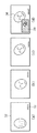
The detection start command input means in S304 is provided in the
例えば図10のような場合がこれに相当する。(a),(b)は録画開始時点と子供(図では人物A)のゴールシーンを示したものである。シーン(a)では、目的とする対象(人物A)よりも、不要物(人物B)が大きく、S307において人物Bで合致判定をしてしまい無駄な画像を取り込んでしまう可能性が高い。その結果、記憶媒体の容量が使われてしまって、本当に必要なシーン(b)では高画質画像を記録することができなくなってしまう恐れがある。このようなときにはユーザがおおよその目的とする対象の状態を判断して検出開始時点を指定すること(図10の場合は人物Aがゴールに近づいて来てから)によって、無駄な画像の取得可能性を大幅に減らすことができる。このとき従来のハイブリッドカメラのように動画がコマ落ちしたり、人間がシャッターを切る場合のように決定的チャンスを逃してしまうといった心配がない。 For example, the case shown in FIG. 10 corresponds to this. (A), (b) shows the goal scene of the recording start time and the child (person A in the figure). In the scene (a), the unnecessary object (person B) is larger than the target object (person A), and it is highly likely that the person B makes a match determination in S307 and takes in useless images. As a result, the capacity of the storage medium is used, and there is a possibility that a high-quality image cannot be recorded in the scene (b) that is really necessary. In such a case, it is possible for the user to acquire a useless image by determining the state of the target object and designating the detection start time (in the case of FIG. 10, the person A approaches the goal). Sex can be greatly reduced. At this time, there is no worry that the moving image drops like a conventional hybrid camera or that a decisive chance is missed like when a human releases the shutter.
また、S304が検出開始指令がなされていない時点ではカメラ制御回路2の負荷が小さくなる。このため、録画時に常に高画質画像をバッファリングして分析処理を行う第1の実施形態と比較して、消費電力の低下を図ったり、他の制御(オートフォーカスや絞り調整など)の頻度を上げることができるといったメリットがある。 In addition, when the detection start command is not issued in S304, the load on the camera control circuit 2 is reduced. For this reason, compared to the first embodiment in which high-quality images are always buffered during recording and analysis processing is performed, the power consumption is reduced and the frequency of other controls (autofocus, aperture adjustment, etc.) is reduced. There is a merit that it can be raised.
[他の実施形態]
以上、本発明に係る実施形態について具体例を用いて詳述したが、本発明は、例えば、システム、装置、方法、プログラム若しくは記憶媒体(記録媒体)等としての実施態様をとることが可能である。具体的には、複数の機器から構成されるシステムに適用しても良いし、また、一つの機器からなる装置に適用しても良い。
[Other Embodiments]
The embodiment according to the present invention has been described in detail using specific examples. However, the present invention can take an embodiment as a system, apparatus, method, program, storage medium (recording medium), or the like. is there. Specifically, the present invention may be applied to a system composed of a plurality of devices, or may be applied to an apparatus composed of a single device.
また、本発明の目的は、図示の機能ブロック及び動作において、いずれの部分をハードウェア回路により実現し、或いはコンピュータを用いたソフトウェア処理によって実現しても達成されることは言うまでもない。 It goes without saying that the object of the present invention can be achieved even if any part of the illustrated functional blocks and operations is realized by a hardware circuit or by software processing using a computer.
尚、本発明は、前述した実施形態の機能を実現するソフトウェアのプログラムを、システムあるいは装置に直接あるいは遠隔から供給することによって達成される場合も含む。その場合、システム等のコンピュータが該プログラムコードを読み出して実行することになる。 Note that the present invention includes a case where the present invention is achieved by supplying a software program for realizing the functions of the above-described embodiments directly or remotely to a system or apparatus. In that case, a computer such as a system reads and executes the program code.
従って、本発明の機能処理をコンピュータで実現するために、該コンピュータにインストールされるプログラムコード自体も本発明を実現するものである。つまり、本発明は、本発明の機能処理を実現するためのコンピュータプログラム自体も含まれる。 Accordingly, since the functions of the present invention are implemented by computer, the program code installed in the computer also implements the present invention. In other words, the present invention includes a computer program itself for realizing the functional processing of the present invention.
その場合、プログラムの機能を有していれば、オブジェクトコード、インタプリタにより実行されるプログラム、OSに供給するスクリプトデータ等の形態であっても良い。 In that case, as long as it has the function of a program, it may be in the form of object code, a program executed by an interpreter, script data supplied to the OS, or the like.
プログラムを供給するための記録媒体(記憶媒体)としては、例えば、フレキシブルディスク、ハードディスク、光ディスク、光磁気ディスク等がある。その他にも、MO、CD-ROM、CD-R、CD-RW、磁気テープ、不揮発性のメモリカード、ROM、DVD(DVD-ROM、DVD-R)等がある。 Examples of the recording medium (storage medium) for supplying the program include a flexible disk, a hard disk, an optical disk, and a magneto-optical disk. In addition, there are MO, CD-ROM, CD-R, CD-RW, magnetic tape, nonvolatile memory card, ROM, DVD (DVD-ROM, DVD-R) and the like.
その他、プログラムの供給方法としては、クライアントコンピュータのブラウザを用いてインターネットのホームページに接続し、該ホームページから本発明のコンピュータプログラムそのものをダウンロードすることもできる。また圧縮され自動インストール機能を含むファイルをハードディスク等の記録媒体にダウンロードすることによっても供給できる。また、本発明のプログラムを構成するプログラムコードを複数のファイルに分割し、それぞれのファイルを異なるホームページからダウンロードすることによっても実現可能である。つまり、本発明の機能処理をコンピュータで実現するためのプログラムファイルを複数のユーザに対してダウンロードさせるWWWサーバも、本発明に含まれるものである。 As another program supply method, a client computer browser can be used to connect to a homepage on the Internet, and the computer program itself of the present invention can be downloaded from the homepage. It can also be supplied by downloading a compressed file including an automatic installation function to a recording medium such as a hard disk. It can also be realized by dividing the program code constituting the program of the present invention into a plurality of files and downloading each file from a different homepage. That is, a WWW server that allows a plurality of users to download a program file for realizing the functional processing of the present invention on a computer is also included in the present invention.
また、本発明のプログラムを暗号化してCD-ROM等の記憶媒体に格納してユーザに配布し、所定の条件をクリアしたユーザが、インターネットを介してホームページから暗号化を解く鍵情報をダウンロードすることもできる。この場合、ダウンロードした鍵情報を使用することにより暗号化されたプログラムを実行してコンピュータにインストールさせて実現する。 In addition, the program of the present invention is encrypted, stored in a storage medium such as a CD-ROM, distributed to users, and a user who satisfies predetermined conditions downloads key information for decryption from a homepage via the Internet. You can also. In this case, using the downloaded key information, the encrypted program is executed and installed in the computer.
また、コンピュータが、読み出したプログラムを実行することによって、前述した実施形態の機能が実現される他、そのプログラムの指示に基づき、コンピュータ上で稼動しているOS等が、実際の処理の一部又は全部を行うことによっても実現され得る。 In addition to the functions of the above-described embodiments being realized by the computer executing the read program, the OS running on the computer based on the instructions of the program may be part of the actual processing. Alternatively, it can be realized by performing all of them.
更に、記録媒体から読み出されたプログラムが、コンピュータに挿入された機能拡張ボードやコンピュータに接続された機能拡張ユニットのメモリに書き込まれた後、該ボード等のCPU等が実際の処理の一部又は全部を行うことによっても実現される。 Further, after the program read from the recording medium is written in the memory of a function expansion board inserted into the computer or a function expansion unit connected to the computer, the CPU of the board or the like performs a part of the actual processing. Alternatively, it can be realized by performing all of them.
1 ユーザインターフェース
2 カメラ制御回路
3 光学系
4 ズーム
5 絞り
6 撮像素子
7 バッファメモリ(第1のデータ保持手段)
8 バッファメモリ(第2のデータ保持手段)
9 画像分析回路
10,11 記録制御回路
12,13 記録媒体
21〜24 顔検出用1次特徴量
25〜28 顔検出用2次特徴量
29 顔検出用3次特徴量(目特徴量)
30 顔検出用3次特徴量(口特徴量)
31 顔検出用4次特徴量(顔特徴量)
32 画像表示部
33 文字情報
34 分析合致画像
35 動画像
36 分析合致領域
DESCRIPTION OF
8 Buffer memory (second data holding means)
9
30 Face detection tertiary feature (mouth feature)
31 quaternary feature value for face detection (face feature value)
32
Claims (9)
前記第2の画像データを用いて被写体が所定の条件を満たしているか分析する分析手段と、
前記第1のバッファメモリに記憶された前記第1の画像データを第1の記録手段に記録し、前記第2のバッファメモリに記憶された前記第2の画像データを第2の記録手段に記録する記録制御手段とを有し、
前記第1の画像データは前記第2の画像データと比較して高解像度及び多階調の少なくともいずれかであって、
前記記録制御手段は、前記分析手段がいずれかのフレームの前記第2の画像データを用いて分析を行った結果、被写体が前記所定の条件を満たしていれば、前記いずれかのフレームの前記第2の画像データと同じタイミングで取り込まれて前記第1のバッファメモリに記憶された前記第1の画像データを前記第1の記録手段へ記録し、被写体が前記所定の条件を満たしていなければ、前記いずれかのフレームの前記第2の画像データと同じタイミングで取り込まれて前記第1のバッファメモリに記憶された前記第1の画像データを前記第1の記録手段へ記録しないことを特徴とする撮像装置。 Moving image data generated by the image sensor is captured and stored as second image data in the second buffer memory, and is stored in the image sensor at the same timing as a predetermined frame of the second image data. Image capturing means for capturing the image data generated in the first buffer memory and storing the image data in the first buffer memory as first image data ;
Analyzing means for analyzing whether the subject satisfies a predetermined condition using the second image data;
Recording the first the first image data stored in the buffer memory is recorded on the first recording means, said second image data stored in said second buffer memory to the second recording means Recording control means for
The first image data is at least one of high resolution and multi-gradation as compared with the second image data,
The recording control means as a result of said analyzing means were analyzed using the second image data of one frame, if they meet the subject is said predetermined condition, said first of said one of the frame The first image data captured at the same timing as the second image data and stored in the first buffer memory is recorded in the first recording means , and the subject does not satisfy the predetermined condition , The first image data fetched at the same timing as the second image data of any one of the frames and stored in the first buffer memory is not recorded in the first recording means . Imaging device.
前記第2の画像データを用いて被写体が所定の条件を満たしているか分析する分析手段と、
前記第1のバッファメモリに記憶された前記第1の画像データを第1の記録手段に記録し、前記第2のバッファメモリに記憶された前記第2の画像データを第2の記録手段に記録する記録制御手段と、
いずれかのフレームの前記第2の画像データが前記所定の条件を満たすときにその旨を通知する通知手段と、
前記通知手段による通知の後に、前記所定の条件を満たす前記いずれかのフレームの第2の画像データと同じタイミングで取り込まれて前記第1のバッファメモリに記憶された第1の画像データを前記第1の記録手段に記録するか否かを選択させる選択手段とを有し、
前記第1の画像データは前記第2の画像データと比較して高解像度及び多階調の少なくともいずれかであって、
前記記録制御手段は、前記選択手段により前記第1の画像データを記録することが選択されれば、前記いずれかのフレームの前記第2の画像データと同じタイミングで取り込まれて前記第1のバッファメモリに記憶された前記第1の画像データを前記第1の記録手段へ記録し、前記選択手段により前記第1の画像データを記録することが選択されなければ、前記いずれかのフレームの前記第2の画像データと同じタイミングで取り込まれて前記第1のバッファメモリに記憶された前記第1の画像データを前記第1の記録手段へ記録しないことを特徴とする撮像装置。 The continuous image data generated by the image sensor is captured and stored as second image data in the second buffer memory, and the image sensor has the same timing as a predetermined frame of the second image data. Image capturing means for capturing the image data generated in the first buffer memory and storing the image data in the first buffer memory as first image data ;
Analyzing means for analyzing whether the subject satisfies a predetermined condition using the second image data;
Recording the first the first image data stored in the buffer memory is recorded on the first recording means, said second image data stored in said second buffer memory to the second recording means Recording control means for
Notifying means for notifying that when the second image data of any frame satisfies the predetermined condition;
After the notification by the notification means , the first image data fetched at the same timing as the second image data of any one of the frames satisfying the predetermined condition and stored in the first buffer memory is stored in the first buffer memory . and a selection means for selecting whether to record the first recording means,
The first image data is at least one of high resolution and multi-gradation as compared with the second image data,
If the recording means selects the first image data to be recorded by the selection means , the recording control means fetches the first buffer at the same timing as the second image data of any one of the frames. The first image data stored in the memory is recorded in the first recording unit , and if the selection unit does not select recording the first image data, the first image data of any one of the frames is recorded . An image pickup apparatus that does not record the first image data captured at the same timing as the second image data and stored in the first buffer memory in the first recording unit .
前記第2の画像データを用いて被写体が所定の条件を満たしているか分析する分析工程と、
前記第1のバッファメモリに記憶された前記第1の画像データを第1の記録手段に記録し、前記第2のバッファメモリに記憶された前記第2の画像データを第2の記録手段に記録する記録制御工程とを有し、
前記第1の画像データは前記第2の画像データと比較して高解像度及び多階調の少なくともいずれかであって、
前記記録制御工程では、前記分析工程にていずれかのフレームの前記第2の画像データを用いて分析を行った結果、被写体が前記所定の条件を満たしていれば、前記いずれかのフレームの前記第2の画像データと同じタイミングで取り込まれて前記第1のバッファメモリに記憶された前記第1の画像データを前記第1の記録手段へ記録し、被写体が前記所定の条件を満たしていなければ、前記いずれかのフレームの前記第2の画像データと同じタイミングで取り込まれて前記第1のバッファメモリに記憶された前記第1の画像データを前記第1の記録手段へ記録しないことを特徴とする撮像方法。 Moving image data generated by the image sensor is captured and stored as second image data in the second buffer memory, and is stored in the image sensor at the same timing as a predetermined frame of the second image data. An image capturing step of capturing the image data generated in the first buffer memory and storing the image data as first image data in a first buffer memory ;
An analysis step of analyzing whether the subject satisfies a predetermined condition using the second image data;
Recording the first the first image data stored in the buffer memory is recorded on the first recording means, said second image data stored in said second buffer memory to the second recording means Recording control step to
The first image data is at least one of high resolution and multi-gradation as compared with the second image data,
In the recording control step, as a result of performing analysis using the second image data of any frame in the analysis step, if the subject satisfies the predetermined condition, the frame of any frame The first image data captured at the same timing as the second image data and stored in the first buffer memory is recorded in the first recording means , and the subject does not satisfy the predetermined condition. The first image data fetched at the same timing as the second image data of any one of the frames and stored in the first buffer memory is not recorded in the first recording means . Imaging method.
前記第2の画像データを用いて被写体が所定の条件を満たしているか分析する分析工程と、
前記第1のバッファメモリに記憶された前記第1の画像データを第1の記録手段に記録し、前記第2のバッファメモリに記憶された前記第2の画像データを第2の記録手段に記録する記録制御工程と、
いずれかのフレームの前記第2の画像データが前記所定の条件を満たすときにその旨を通知する通知工程と、
前記通知工程による通知の後に、前記所定の条件を満たす前記いずれかのフレームの第2の画像データと同じタイミングで取り込まれて前記第1のバッファメモリに記憶された第1の画像データを前記第1の記録手段に記録するか否かを選択させる選択工程とを有し、
前記第1の画像データは前記第2の画像データと比較して高解像度及び多階調の少なくともいずれかであって、
前記記録制御工程では、前記選択工程により前記第1の画像データを記録することが選択されれば、前記いずれかのフレームの前記第2の画像データと同じタイミングで取り込まれて前記第1のバッファメモリに記憶された前記第1の画像データを前記第1の記録手段へ記録し、前記選択工程により前記第1の画像データを記録することが選択されなければ、前記いずれかのフレームの前記第2の画像データと同じタイミングで取り込まれて前記第1のバッファメモリに記憶された前記第1の画像データを前記第1の記録手段へ記録しないことを特徴とする撮像方法。 The continuous image data generated by the image sensor is captured and stored as second image data in the second buffer memory, and the image sensor has the same timing as a predetermined frame of the second image data. An image capturing step of capturing the image data generated in the first buffer memory and storing the image data as first image data in a first buffer memory ;
An analysis step of analyzing whether the subject satisfies a predetermined condition using the second image data;
Recording the first the first image data stored in the buffer memory is recorded on the first recording means, said second image data stored in said second buffer memory to the second recording means Recording control process to
A notification step of notifying that when the second image data of any frame satisfies the predetermined condition;
After the notification in the notification step , the first image data fetched at the same timing as the second image data of any one of the frames satisfying the predetermined condition and stored in the first buffer memory is stored in the first buffer memory . And a selection step for selecting whether or not to record in one recording means ,
The first image data is at least one of high resolution and multi-gradation as compared with the second image data,
In the recording control step, if recording of the first image data is selected in the selection step, the first buffer is captured at the same timing as the second image data of any one of the frames. The first image data stored in the memory is recorded in the first recording means , and if the selection of the first image data is not selected in the selection step, the first image data of any one of the frames is selected . An image pickup method, wherein the first image data captured at the same timing as the second image data and stored in the first buffer memory is not recorded in the first recording means .
Priority Applications (7)
| Application Number | Priority Date | Filing Date | Title |
|---|---|---|---|
| JP2005215981A JP4717539B2 (en) | 2005-07-26 | 2005-07-26 | Imaging apparatus and imaging method |
| EP06015037A EP1748378B1 (en) | 2005-07-26 | 2006-07-19 | Image capturing apparatus and image capturing method |
| DE602006009191T DE602006009191D1 (en) | 2005-07-26 | 2006-07-19 | Imaging device and method |
| US11/459,112 US7889886B2 (en) | 2005-07-26 | 2006-07-21 | Image capturing apparatus and image capturing method |
| KR1020060070101A KR100911695B1 (en) | 2005-07-26 | 2006-07-26 | Image capturing apparatus and image capturing method |
| CN2006101039023A CN1905629B (en) | 2005-07-26 | 2006-07-26 | Image capturing apparatus and image capturing method |
| US12/691,072 US8180106B2 (en) | 2005-07-26 | 2010-01-21 | Image capturing apparatus and image capturing method |
Applications Claiming Priority (1)
| Application Number | Priority Date | Filing Date | Title |
|---|---|---|---|
| JP2005215981A JP4717539B2 (en) | 2005-07-26 | 2005-07-26 | Imaging apparatus and imaging method |
Publications (3)
| Publication Number | Publication Date |
|---|---|
| JP2007036586A JP2007036586A (en) | 2007-02-08 |
| JP2007036586A5 JP2007036586A5 (en) | 2008-09-11 |
| JP4717539B2 true JP4717539B2 (en) | 2011-07-06 |
Family
ID=37674745
Family Applications (1)
| Application Number | Title | Priority Date | Filing Date |
|---|---|---|---|
| JP2005215981A Active JP4717539B2 (en) | 2005-07-26 | 2005-07-26 | Imaging apparatus and imaging method |
Country Status (2)
| Country | Link |
|---|---|
| JP (1) | JP4717539B2 (en) |
| CN (1) | CN1905629B (en) |
Families Citing this family (27)
| Publication number | Priority date | Publication date | Assignee | Title |
|---|---|---|---|---|
| JP2008197889A (en) * | 2007-02-13 | 2008-08-28 | Nippon Telegr & Teleph Corp <Ntt> | Still image creation method, still image creation device and still image creation program |
| CN101731004B (en) * | 2007-04-23 | 2012-07-04 | 夏普株式会社 | Image picking-up device, computer readable recording medium including recorded program for control of the device, and control method |
| JP2009010776A (en) | 2007-06-28 | 2009-01-15 | Sony Corp | Imaging device, photography control method, and program |
| JP4853425B2 (en) | 2007-08-14 | 2012-01-11 | ソニー株式会社 | Imaging apparatus, imaging method, and program |
| JP4882956B2 (en) * | 2007-10-22 | 2012-02-22 | ソニー株式会社 | Image processing apparatus and image processing method |
| JP5473260B2 (en) * | 2008-06-27 | 2014-04-16 | キヤノン株式会社 | Imaging device |
| EP2148499B1 (en) | 2008-07-25 | 2018-01-17 | FUJIFILM Corporation | Imaging apparatus and method |
| KR101542436B1 (en) * | 2008-07-29 | 2015-08-06 | 후지필름 가부시키가이샤 | Imaging apparatus and imaging method |
| CN101753829B (en) * | 2008-12-09 | 2012-10-03 | 财团法人资讯工业策进会 | Hand-off video signal monitoring method and system and computer device |
| JP5397059B2 (en) * | 2009-07-17 | 2014-01-22 | ソニー株式会社 | Image processing apparatus and method, program, and recording medium |
| KR101038323B1 (en) * | 2009-09-24 | 2011-06-01 | 주식회사 팬택 | Picture frame processing apparatus used image recognition technicque |
| CN102148919B (en) * | 2010-02-09 | 2015-05-27 | 新奥特(北京)视频技术有限公司 | Method and system for detecting balls |
| JP5569357B2 (en) * | 2010-11-19 | 2014-08-13 | 富士通株式会社 | Image processing apparatus, image processing method, and image processing program |
| WO2013100924A1 (en) * | 2011-12-28 | 2013-07-04 | Intel Corporation | Virtual shutter image capture |
| AU2013205613B2 (en) * | 2012-05-04 | 2017-12-21 | Samsung Electronics Co., Ltd. | Terminal and method for controlling the same based on spatial interaction |
| CN103776543A (en) * | 2012-09-21 | 2014-05-07 | 杭州美盛红外光电技术有限公司 | Thermal image analysis device and thermal image analysis method |
| US20150350571A1 (en) * | 2012-12-27 | 2015-12-03 | Hao Wang | Device and method for selecting thermal images |
| CN103716564B (en) * | 2013-12-09 | 2017-02-15 | 乐视致新电子科技(天津)有限公司 | Method and device for adjusting control parameter value |
| US10074003B2 (en) * | 2014-07-11 | 2018-09-11 | Intel Corporation | Dynamic control for data capture |
| US9571725B2 (en) * | 2014-09-02 | 2017-02-14 | Htc Corporation | Electronic device and image capture method thereof |
| JP6308161B2 (en) * | 2015-03-31 | 2018-04-11 | 株式会社エクォス・リサーチ | Pulse wave detection device and pulse wave detection program |
| JP2017153330A (en) * | 2016-02-26 | 2017-08-31 | 河村電器産業株式会社 | Demand monitoring device |
| CN107786803A (en) * | 2016-08-29 | 2018-03-09 | 中兴通讯股份有限公司 | A kind of image generating method, device and terminal device |
| CN108230292B (en) * | 2017-04-11 | 2021-04-02 | 北京市商汤科技开发有限公司 | Object detection method, neural network training method, device and electronic equipment |
| JP7401968B2 (en) * | 2018-12-07 | 2023-12-20 | ルネサスエレクトロニクス株式会社 | Shooting control device, shooting system, and shooting control method |
| JP2020136899A (en) * | 2019-02-19 | 2020-08-31 | ソニーセミコンダクタソリューションズ株式会社 | Imaging apparatus, electronic apparatus and imaging method |
| CN110929756B (en) * | 2019-10-23 | 2022-09-06 | 广物智钢数据服务(广州)有限公司 | Steel size and quantity identification method based on deep learning, intelligent equipment and storage medium |
Citations (2)
| Publication number | Priority date | Publication date | Assignee | Title |
|---|---|---|---|---|
| JP2001094923A (en) * | 1999-09-20 | 2001-04-06 | Canon Inc | Image recorder, method and computer-readable storage medium |
| JP2004180076A (en) * | 2002-11-28 | 2004-06-24 | Fuji Photo Film Co Ltd | Imaging device, imaging method, and image processing device |
Family Cites Families (5)
| Publication number | Priority date | Publication date | Assignee | Title |
|---|---|---|---|---|
| JP4123586B2 (en) * | 1997-08-26 | 2008-07-23 | 株式会社ニコン | Electronic camera |
| US6964023B2 (en) * | 2001-02-05 | 2005-11-08 | International Business Machines Corporation | System and method for multi-modal focus detection, referential ambiguity resolution and mood classification using multi-modal input |
| US6662093B2 (en) * | 2001-05-30 | 2003-12-09 | Eaton Corporation | Image processing system for detecting when an airbag should be deployed |
| GB2378339A (en) * | 2001-07-31 | 2003-02-05 | Hewlett Packard Co | Predictive control of multiple image capture devices. |
| JP2004294498A (en) * | 2003-03-25 | 2004-10-21 | Fuji Photo Film Co Ltd | Automatic photographing system |
-
2005
- 2005-07-26 JP JP2005215981A patent/JP4717539B2/en active Active
-
2006
- 2006-07-26 CN CN2006101039023A patent/CN1905629B/en not_active Expired - Fee Related
Patent Citations (2)
| Publication number | Priority date | Publication date | Assignee | Title |
|---|---|---|---|---|
| JP2001094923A (en) * | 1999-09-20 | 2001-04-06 | Canon Inc | Image recorder, method and computer-readable storage medium |
| JP2004180076A (en) * | 2002-11-28 | 2004-06-24 | Fuji Photo Film Co Ltd | Imaging device, imaging method, and image processing device |
Also Published As
| Publication number | Publication date |
|---|---|
| JP2007036586A (en) | 2007-02-08 |
| CN1905629B (en) | 2010-06-02 |
| CN1905629A (en) | 2007-01-31 |
Similar Documents
| Publication | Publication Date | Title |
|---|---|---|
| JP4717539B2 (en) | Imaging apparatus and imaging method | |
| JP4640456B2 (en) | Image recording apparatus, image recording method, image processing apparatus, image processing method, and program | |
| EP2053843B1 (en) | Camera and Image Recording Program Product | |
| JP4581924B2 (en) | Image reproducing apparatus and image reproducing program | |
| KR101709935B1 (en) | Image photographing apparatus and control method thereof | |
| JP4869270B2 (en) | Imaging apparatus and image reproduction apparatus | |
| JP4431547B2 (en) | Image display control device, control method therefor, and control program therefor | |
| JP4605039B2 (en) | Automatic photographing method, automatic photographing apparatus and automatic photographing program | |
| JP5516662B2 (en) | Imaging device | |
| US8502883B2 (en) | Photographing apparatus and photographing control method | |
| JP2000023012A5 (en) | ||
| JP5137622B2 (en) | Imaging apparatus and control method thereof, image processing apparatus and control method thereof | |
| JP2007142565A (en) | Imaging apparatus and method thereof | |
| JP2007027971A (en) | Photographing apparatus, control method thereof, program, and recording medium | |
| JP2007049631A (en) | Imaging apparatus | |
| JP3955540B2 (en) | Image processing device | |
| JP2010178259A (en) | Digital camera | |
| JP2005323015A (en) | Digital camera | |
| JP6866210B2 (en) | Image processing equipment, image processing methods and programs | |
| JP2005323014A (en) | Digital camera | |
| JP2010237911A (en) | Electronic apparatus | |
| JP2007096440A (en) | Imaging apparatus | |
| JP4849330B2 (en) | Display control apparatus and method, imaging apparatus, information processing apparatus and method, and program | |
| JP2001094919A (en) | Device and method for recording image and computer- readable storage medium | |
| JP5157761B2 (en) | Electronic still camera |
Legal Events
| Date | Code | Title | Description |
|---|---|---|---|
| A521 | Request for written amendment filed |
Free format text: JAPANESE INTERMEDIATE CODE: A523 Effective date: 20080724 |
|
| A621 | Written request for application examination |
Free format text: JAPANESE INTERMEDIATE CODE: A621 Effective date: 20080724 |
|
| A977 | Report on retrieval |
Free format text: JAPANESE INTERMEDIATE CODE: A971007 Effective date: 20100301 |
|
| A131 | Notification of reasons for refusal |
Free format text: JAPANESE INTERMEDIATE CODE: A131 Effective date: 20100618 |
|
| A521 | Request for written amendment filed |
Free format text: JAPANESE INTERMEDIATE CODE: A523 Effective date: 20100804 |
|
| TRDD | Decision of grant or rejection written | ||
| A01 | Written decision to grant a patent or to grant a registration (utility model) |
Free format text: JAPANESE INTERMEDIATE CODE: A01 Effective date: 20110328 |
|
| A01 | Written decision to grant a patent or to grant a registration (utility model) |
Free format text: JAPANESE INTERMEDIATE CODE: A01 |
|
| A61 | First payment of annual fees (during grant procedure) |
Free format text: JAPANESE INTERMEDIATE CODE: A61 Effective date: 20110330 |
|
| R150 | Certificate of patent or registration of utility model |
Ref document number: 4717539 Country of ref document: JP Free format text: JAPANESE INTERMEDIATE CODE: R150 Free format text: JAPANESE INTERMEDIATE CODE: R150 |
|
| FPAY | Renewal fee payment (event date is renewal date of database) |
Free format text: PAYMENT UNTIL: 20140408 Year of fee payment: 3 |