JP4717379B2 - Suture securing device with improved drive head - Google Patents
Suture securing device with improved drive head Download PDFInfo
- Publication number
- JP4717379B2 JP4717379B2 JP2004171469A JP2004171469A JP4717379B2 JP 4717379 B2 JP4717379 B2 JP 4717379B2 JP 2004171469 A JP2004171469 A JP 2004171469A JP 2004171469 A JP2004171469 A JP 2004171469A JP 4717379 B2 JP4717379 B2 JP 4717379B2
- Authority
- JP
- Japan
- Prior art keywords
- suture
- head portion
- drive head
- tunnel
- driving
- Prior art date
- Legal status (The legal status is an assumption and is not a legal conclusion. Google has not performed a legal analysis and makes no representation as to the accuracy of the status listed.)
- Active
Links
Images


Classifications
-
- A—HUMAN NECESSITIES
- A61—MEDICAL OR VETERINARY SCIENCE; HYGIENE
- A61B—DIAGNOSIS; SURGERY; IDENTIFICATION
- A61B17/00—Surgical instruments, devices or methods, e.g. tourniquets
- A61B17/04—Surgical instruments, devices or methods, e.g. tourniquets for suturing wounds; Holders or packages for needles or suture materials
- A61B17/0401—Suture anchors, buttons or pledgets, i.e. means for attaching sutures to bone, cartilage or soft tissue; Instruments for applying or removing suture anchors
- A61B2017/0409—Instruments for applying suture anchors
-
- A—HUMAN NECESSITIES
- A61—MEDICAL OR VETERINARY SCIENCE; HYGIENE
- A61B—DIAGNOSIS; SURGERY; IDENTIFICATION
- A61B17/00—Surgical instruments, devices or methods, e.g. tourniquets
- A61B17/04—Surgical instruments, devices or methods, e.g. tourniquets for suturing wounds; Holders or packages for needles or suture materials
- A61B17/0401—Suture anchors, buttons or pledgets, i.e. means for attaching sutures to bone, cartilage or soft tissue; Instruments for applying or removing suture anchors
- A61B2017/0414—Suture anchors, buttons or pledgets, i.e. means for attaching sutures to bone, cartilage or soft tissue; Instruments for applying or removing suture anchors having a suture-receiving opening, e.g. lateral opening
-
- A—HUMAN NECESSITIES
- A61—MEDICAL OR VETERINARY SCIENCE; HYGIENE
- A61B—DIAGNOSIS; SURGERY; IDENTIFICATION
- A61B17/00—Surgical instruments, devices or methods, e.g. tourniquets
- A61B17/04—Surgical instruments, devices or methods, e.g. tourniquets for suturing wounds; Holders or packages for needles or suture materials
- A61B17/0401—Suture anchors, buttons or pledgets, i.e. means for attaching sutures to bone, cartilage or soft tissue; Instruments for applying or removing suture anchors
- A61B2017/044—Suture anchors, buttons or pledgets, i.e. means for attaching sutures to bone, cartilage or soft tissue; Instruments for applying or removing suture anchors with a threaded shaft, e.g. screws
Description
本発明は改善された物理特性を有する縫合糸固定装置に関連しており、特に、一定の高い破壊トルクを有する縫合糸固定装置に関連している。 The present invention relates to a suture anchoring device having improved physical properties, and in particular to a suture anchoring device having a constant high breaking torque.
分離した軟質組織を骨に固定するための縫合糸を使用するために一定の長さの縫合糸を骨に対して取り付けるために種々の縫合糸の固定装置が用いられる場合が多い。これらの縫合糸固定装置は一般的に一定の固定本体部分、一定の縫合糸取付用の特徴部分、および当該縫合糸固定装置を一定の骨の中に保持するための一定の骨嵌合用の特徴部分を有している。この固定装置は骨の中における一定の孔あけ処理した穴の中に挿入することができ、さらに/または、この固定装置は自己ねじ立て性にすることができ、それゆえ、その固定装置を骨の中に嵌合するためのねじ山を含むことができる。たいていの縫合糸固定装置はその縫合糸固定装置を骨の中に駆動するための一定の挿入工具の使用を必要としている。このような挿入工具は一般的に一定の縫合糸固定装置のヘッド部分の上にまたはその中に形成されている一定の対応する嵌合用の特徴部分に対して係合するためにその先端部に形成されている一定の嵌合用の特徴部分を有する一定の細長いシャンクにより形成されている。一例の一般的な様式の駆動用工具は一定の縫合糸固定装置における一定の対応する六角形状または正方形状のヘッド部分を受容するための一定の六角形状または正方形状のソケットを有している。 Various suture anchors are often used to attach a length of suture to the bone in order to use the suture to secure the separated soft tissue to the bone. These suture anchors generally have a fixed body portion, a suture attachment feature, and a bone fitting feature to hold the suture anchor in a bone. Has a part. The fixation device can be inserted into a perforated hole in the bone and / or the fixation device can be self-twisting and therefore the fixation device can be Threads can be included for mating. Most suture anchors require the use of an insertion tool to drive the suture anchor into the bone. Such an insertion tool is generally at the tip for engagement with a corresponding mating feature formed on or in the head portion of the suture anchor. It is formed by an elongate shank having a formed mating feature. An exemplary common style drive tool has a hexagonal or square socket for receiving a corresponding hexagonal or square head portion in a suture anchor.
従来の縫合糸固定装置および縫合糸固定装置用の駆動装置は十分ではあるが、幾つかの欠陥を有している。例えば、六角形状および正方形状の固定用のヘッド部分は比較的に低い抜取り強さを有する傾向がある。このことは上記固定用のヘッド部分の構造的な完全性に起因すると考えられ、その構造は一定の縫合糸をその固定用のヘッド部分に対して取り付けるために用いる上記取付用の特徴部分により弱められる場合がある。従って、この取付用の特徴部分が上記駆動装置に対して作用を及ぼす固定装置における材料の量を減少すれば、その駆動用のヘッド部分から除去するか「抜き取る(stripped)」ことを必要とする材料の量が減少されて、そのヘッド部分の抜取り強さが低下する。 While conventional suture anchors and drives for suture anchors are sufficient, they have several deficiencies. For example, hexagonal and square fixing head portions tend to have a relatively low extraction strength. This is believed to be due to the structural integrity of the fixation head portion, which is weakened by the attachment features used to attach a suture to the fixation head portion. May be. Thus, if this mounting feature reduces the amount of material in the fixation device that acts on the drive, it must be removed or "stripped" from the drive head. The amount of material is reduced and the extraction strength of the head portion is reduced.
さらに、従来の縫合糸固定装置のヘッド部分は比較的に低い破壊トルクを有する傾向があり、このことはそのヘッド部分の挿入時における剪断を生じる可能性がある。このような様式の破壊はまた上記固定用のヘッド部分における縫合糸取付用の特徴部分の位置により生じる可能性もあり、この破壊はその駆動用のヘッド部分の全体の断面積を減少する可能性がある。フロリダ州、ナポリのアルスレックス社(Arthrex, Inc.)により製造されているバイオコルクスクリュー(Biocorkscrew)(商標)固定装置は当該固定装置の構造的な完全性に対して作用を及ぼすことのできる一定の縫合糸取付用の特徴部分を有する縫合糸固定装置の一例である。特に、一定のループが一定の縫合糸を受容するためにそのループが上記固定装置のヘッド部分から外側に延出するようにその固定装置の中に成形および埋め込まれている。このような固定装置を通したループ付きの縫合糸の配置の結果として、その全体の固定用のヘッド部分が比較的に弱体化するために、挿入中に剪断される可能性がある。 In addition, the head portion of conventional suture anchors tends to have a relatively low breaking torque, which can cause shearing upon insertion of the head portion. This type of failure may also occur due to the location of the suture attachment feature in the locking head portion, which may reduce the overall cross-sectional area of the drive head portion. There is. The Biocorkscrew (TM) fastening device manufactured by Arthrex, Inc. of Naples, Florida is a constant that can affect the structural integrity of the fastening device. 1 is an example of a suture fixing device having a feature for attaching a suture thread. In particular, a loop is molded and embedded in the fixation device such that the loop extends outwardly from the head portion of the fixation device to receive a suture. As a result of the placement of the looped suture through such an anchoring device, its entire anchoring head portion may be sheared during insertion due to its relatively weakening.
一定の固定用ヘッド部分の破壊トルクを減少する一例の選択肢はそのヘッド部分の大きさを増すことである。しかしながら、大形の固定用のヘッド部分は一定の大形の駆動用工具を必要とし、このことはさらに比較的に大きな骨のトンネルを骨に形成することを必要とする。このことは、特に、その骨のトンネルを海綿質の中に形成することが必要である場合に望ましくない。従って、たいていの縫合糸固定装置は比較的に小形の駆動用工具とともに使用するために適合しており、それゆえ、これらは一定の低い破壊トルクおよび一定の低い抜取り強さを生じる可能性のある一定の比較的に小形の駆動用ヘッド部分を有している。
従って、改善された物理的特性を有する、特に、一定の高い破壊トルクおよび一定の高い抜取り強さを有する縫合糸固定装置に対する要望が依然として存在している。 Accordingly, there remains a need for a suture anchoring device that has improved physical properties, in particular, a constant high breaking torque and a constant high withdrawal strength.
本発明は一般に一定の長手軸を定めていて上部に形成されている少なくとも1個の骨係合用のねじ山を有している一定の細長いシャンク、および一定の基端部および上記細長いシャンクに対して嵌合している一定の先端部を有する一定の駆動用ヘッド部分を備えている一定の縫合糸固定装置を提供している。上記駆動用ヘッド部分は一定の実質的に卵形の形状および当該駆動用ヘッド部分の一部分において形成されている少なくとも1個の縫合糸取付部材を有している。この駆動用ヘッド部分の構成はこの駆動用ヘッド部分が一定の高い破壊トルクおよび一定の高い抜取り強さを含む改善された物理的特性を有する一定の縫合糸固定装置を提供している点において特に有利である。一定の例示的な実施形態において、上記駆動用ヘッド部分は少なくとも約5.0インチ・ポンドの一定の破壊トルクを有しており、さらにこの駆動用ヘッド部分は少なくとも約60ポンド・フォース(lbf)の一定の引張強さを有している。 The present invention is generally directed to an elongated shank having a longitudinal axis and having at least one bone engaging thread formed thereon, and an proximal end and the elongated shank. A suture anchoring device is provided that includes a drive head portion with a fixed distal end that fits together. The drive head portion has a substantially ovoid shape and at least one suture attachment member formed in a portion of the drive head portion. This drive head portion configuration is particularly advantageous in that the drive head portion provides a suture fixation device having improved physical properties including a constant high breaking torque and a high withdrawal strength. It is advantageous. In certain exemplary embodiments, the drive head portion has a constant breaking torque of at least about 5.0 inch-pound, and the drive head portion is at least about 60 pound-force (lbf). It has a certain tensile strength.
一例の実施形態において、上記縫合糸取付部材は少なくとも1個の縫合糸トンネルを有しており、この縫合糸トンネルは上記駆動用ヘッド部分を、横方向にまたは当該縫合糸トンネルが上記縫合糸固定装置の長手軸に交差するように、貫通している。また、上記縫合糸取付部材は上記駆動用ヘッド部分の一定の外表面部に形成されていて上記少なくとも1個の縫合糸トンネルのそれぞれの開口部から始まってその基端側に延在している一定の長手方向に沿って配向している縫合糸受容用の通路を含むこともできる。さらに、一定の例示的な実施形態において、上記の縫合糸通路は上記駆動用ヘッド部分の中に一定の無通路部分を存在させるために当該駆動用ヘッド部分の先端部よりも基端側に形成されている。この無通路部分は上記縫合糸固定装置の駆動用ヘッド部分に対して付加的な構造的完全性を与えて挿入中における剪断の危険性を最少にする。また、別の例示的な実施形態においては、上記駆動用ヘッド部分は当該駆動用ヘッド部分から基端側に延在している第1の対の対向状の縫合糸受容用の通路を有する第1の縫合糸トンネル、および当該駆動用ヘッド部分から基端側に延在している第2の対の対向状の縫合糸受容用の通路を有する第2の縫合糸トンネルを有している。 In one example embodiment, the suture attachment member includes at least one suture tunnel, the suture tunnel securing the drive head portion laterally or the suture tunnel securing the suture. It penetrates to intersect the longitudinal axis of the device. The suture attachment member is formed on a fixed outer surface portion of the driving head portion, and starts from each opening of the at least one suture tunnel and extends to the proximal end side thereof. It may also include a suture receiving passage oriented along a certain longitudinal direction. Further, in certain exemplary embodiments, the suture passage is formed proximal to the distal end of the drive head portion in order to have a constant passage-free portion in the drive head portion. Has been. This passageless portion provides additional structural integrity to the drive head portion of the suture anchor and minimizes the risk of shear during insertion. In another exemplary embodiment, the drive head portion includes a first pair of opposed suture receiving passages extending proximally from the drive head portion. And a second suture tunnel having a second pair of opposed suture receiving passages extending proximally from the drive head portion.
別の態様において、少なくとも1個の縫合糸固定装置および一定の円筒形の駆動用工具を含む一定の縫合糸固定装置および取付キットが提供されている。この縫合糸固定装置は上部に形成されている骨係合用のねじ山を有していて一定の長手軸を定めている一定のシャンクを有している。さらに、一定の駆動用ヘッド部分が上記シャンクに形成されており、少なくとも1個の長手方向に沿って配向されている縫合糸受容用の通路が内部に形成されている一定の卵形の形状を有している。さらに、上記円筒形の駆動用工具は内部に一定のソケットが形成されている一定の先端部を有しており、この先端部は上記縫合糸固定装置の駆動用ヘッド部分を受容してこれに係合することに適合している一定の卵形の形状を有している。一定の例示的な実施形態において、上記駆動用工具は上記縫合糸固定装置の一定の最大外径に等しいかこれよりも小さい一定の外径を有している。 In another aspect, a suture fixation device and attachment kit are provided that include at least one suture fixation device and a cylindrical drive tool. The suture anchor has a shank with a bone engaging thread formed in the upper portion and defining a longitudinal axis. Furthermore, a constant driving head portion is formed in the shank, and at least one suture receiving passage oriented along the longitudinal direction is formed therein. Have. Further, the cylindrical driving tool has a fixed tip portion in which a fixed socket is formed, and the tip portion receives and receives the driving head portion of the suture fixing device. It has an oval shape that is adapted to engage. In certain exemplary embodiments, the driving tool has a constant outer diameter that is less than or equal to a certain maximum outer diameter of the suture anchoring device.
さらに、本発明による一定の縫合糸固定装置を使用するための方法もまた提供されている。 Furthermore, a method for using a suture anchoring device according to the present invention is also provided.
従って、本発明によれば、改善された物理的特性を有する、特に、一定の高い破壊トルクおよび一定の高い抜取り強さを有する縫合糸固定装置が提供できる。 Thus, the present invention can provide a suture anchoring device having improved physical properties, in particular having a constant high breaking torque and a constant high withdrawal strength.
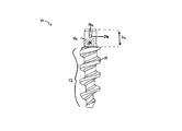
図1Aおよび図1Bにおいて示されているように、本発明は一般に一定の長手軸Aを定めていて上部において形成されている少なくとも1個の骨係合用のねじ山14を有している一定の細長いシャンク12、および一定の基端部16aおよび上記細長いシャンク12に対して係合している一定の先端部16bを有している一定の駆動用ヘッド部分16を備えている一定の縫合糸固定装置10を提供している。上記駆動用ヘッド部分16は一定の実質的に卵形の形状を有しており、その内部に形成されている少なくとも1個の縫合糸取付部材を含む。この駆動用ヘッド部分16の構成は当該駆動用ヘッド部分16が一定の高い破壊トルクおよび一定の高い抜取り強さを含む改善された物理的特性を有する一定の縫合糸固定装置10を提供している点において特に有利である。
As shown in FIGS. 1A and 1B, the present invention generally includes a constant longitudinal axis A and has at least one
上記縫合糸固定装置10の細長いシャンク12は種々の構成を有することができ、その上部に形成されている種々の異なる骨係合用の特徴部分を有することができる。図1Aおよび図1Bは一定のシャンク12を有する一定の骨固定装置10の例示的な実施形態をそれぞれ示しており、このシャンク12は一定のコア20および当該シャンク12における一定の基端部12aから一定の先端部12bまでそのコア20の周囲に延在している単一の螺旋状のねじ山14を有している。さらに、このねじ山14は基端側および先端側の対向状のフランク14a,14bを有しており、これらは一定の付け根部分14cと一定の実質的に平坦化されている頂上部分14dとの間にそれぞれ延在している。このねじ山14はシャンク12の一定の大径部分d2 を定めており、この大径部分はシャンク12の長さに沿って変更可能であるが、この大径部分d2 は好ましくはシャンク12における一定の実質的な部分に沿って実質的に一定である。しかしながら、このねじ山14はシャンク12の先端部を形成している一定の頂点22に到達しているシャンク12の先端部分においてテーパー状にすることができる。一方、上記シャンク12のコア20は一定の小径部分d1 を定めており、この小径部分はシャンク12の長さに沿って実質的に一定にすることができ、変化することも可能である。図1Aにおいて示されているように、上記コア20は一定の基端部12aから一定の先端部12bまでテーパー状である。当該技術分野における熟練者であれば、図1Aにおいて示されているシャンク12が単に一定のシャンク12の例示的な実施形態に過ぎないこと、および異なる骨係合用の特徴部分を有する種々の異なるシャンクが本発明による一定の縫合糸固定装置10と共に使用可能であることが認識できる。
The
上記縫合糸固定装置10のヘッド部分16が図1Cおよび図1Dにおいてさらに詳細に示されており、このヘッド部分16は上記シャンク12に取り付けられているか、さらに好ましくは、当該シャンク12と一体に形成されている。このヘッド部分16は一定の小径部分x1 および一定の大径部分x2 を定めている一定の概ね卵形の形状を有している。一定の例示的な実施形態において、このヘッド部分16の小径部分x1 はこのヘッド部分の大径部分x2 の寸法の約4分の3(3/4)であり、このヘッド部分16の大径部分x2 は上記シャンク12の小径部分d1 に等しいかこれよりも小さい。このようなシャンク12の小径部分d1 に対して比べた場合に相対的に小さい寸法のヘッド部分16における大径部分x2 は当該ヘッド部分16が必要以上に大きな骨のトンネルを骨の中に形成することを必要としないので特に望ましい。さらに、このヘッド部分16はその基端部16aおよび16bの間に延在している一定の長さLh (図1Bにおいて示されている)を有している。このヘッド部分16の長さLh は変更可能であるが、好ましくは、このヘッド部分16の長さLh はこのヘッド部分が一定の駆動用工具の中に受容されて剪断により除去されることなく骨の中に駆動されることを可能にするために最適化されている。
The
さらに、上記縫合糸固定装置10のヘッド部分16は1個以上の縫合糸を受容するためにその上部またはその内部において形成されている少なくとも1個の縫合糸取付部材を有している。この場合に、種々の縫合糸取付部材が使用可能であるが、図1A乃至図1Dは第1および第2の縫合糸トンネル26(1個のトンネル26だけが示されている)を有する縫合糸固定装置10の一定の例示的な実施形態を示しており、これらの縫合糸26は上記ヘッド部分を貫通しており、一定の長さの縫合糸がその中に配置されることを可能にしている。この第1および第2の縫合糸トンネルは上記固定用ヘッド部分の中に事実上において任意の配向で延在できるが、好ましくはこれらはそれぞれのトンネルが交差することを防ぐために上記固定装置10の長手軸Aに沿う異なる位置において上記固定用ヘッド部分16の中に横方向に貫通していて、当該ヘッド部分16の構造的な完全性を保っている。一例の例示的な実施形態において、上記の縫合糸トンネルはヘッド部分16に一定の無通路部分24(図1Bにおいて示されている)を備えるために駆動用ヘッド部分16の先端部16bよりも基端側の一定の位置まで到達している。この固定用ヘッド部分16の先端側の部分は一般的に挿入中に最も大きな応力が加えられる固定装置10の部分であるので、上記のような無通路部分24は挿入中の剪断の危険性を最少にする固定用ヘッド部分16における一定のはるかに強度の高い密度の大きな部分を構成している。
In addition, the
上記縫合糸固定装置10はまた随意的にその内部に形成されている4個の長手方向に沿って配向されている縫合糸受容用の溝部または通路18a,18b,18c,18dを含むことができる。これらの縫合糸受容用の通路18a,18b,18c,18dは上記ヘッド部分16の外表面部に形成されていて、好ましくは互いに等距離の間隔を有している。図1Dにおいて示されているように、2個の対向状の縫合糸受容用の通路18d,18bは固定用ヘッド部分16の大径部分x2 に沿って配置されており、別の2個の対向状の縫合糸受容用の通路18a,18cはヘッド部分16の小径部分x1 に沿って配置されている。これらの縫合糸受容用の通路18a,18b,18c,18dの位置はまた変更可能であるが、好ましくは、これらは駆動用ヘッド部分16の基端側の表面16cを貫通してそれぞれの対応している縫合糸トンネルの一定の開口部まで延在している。なお、それぞれの縫合糸トンネルが駆動用ヘッド部分16の先端部16bよりも基端側に配置されている場合に、それぞれの縫合糸受容用の通路18a,18b,18c,18dもまた駆動用ヘッド部分16の先端部16bよりも基端側の一定の位置まで延在していて当該ヘッド部分16に一定の無通路部分24(図1Bにおいて示されている)を形成していることが好ましい。さらに、2個の縫合糸通路が上記駆動用ヘッド部分16の長さに沿う異なる位置に備えられている場合には、第1の対の対向状の縫合糸受容用の通路、例えば、縫合糸受容用の通路18a,18bは、図1Cにおいて示されているように、第2の対の縫合糸受容用の通路、例えば、縫合糸受容用の通路18c,18dの長さL2 と異なる一定の長さL1 を有することができる。
The
さらに、上記のそれぞれの縫合糸受容用の通路18a,18b,18c,18dの大きさおよび深さもまた変更可能であるが、一定の縫合線をヘッド部分16に対して同一平面状か平面下の状態で支持してその縫合線による作用を伴わずに一定の駆動用工具によりヘッド部16を係合可能にする必要がある。一定の例示的な実施形態において、約20%乃至30%、さらに好ましくは約28%の上記駆動用ヘッド部分16の断面の表面積が上記縫合糸受容用の通路18a,18b,18c,18dを形成するために除去されている。この結果、内部に縫合糸受容用の通路18a,18b,18c,18dが形成されているこの駆動用ヘッド部分16は当該駆動用ヘッド部分16の一定の境界線内における一定の公称の断面積の約72%を占める最も基端側の表面における一定の断面の表面積を有する。
Further, the size and depth of each of the
当該技術分野における熟練者であれば、一定の縫合糸を一定の固定装置に取り付けるために種々の技法が使用可能であること、および上記固定装置10が1個以上の縫合糸受容用のトンネルおよび/または1個以上の縫合糸受容用の通路を有することに限定されないことが認識できる。
Those skilled in the art can use various techniques to attach a suture to a fixation device, and that the
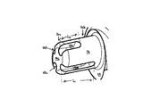
使用時において、上記縫合糸固定装置10は、図2Aにおいて示されている工具50等のような、一定の駆動用の工具により骨の中に駆動できる。この駆動用工具50は種々の形状および大きさを有することができるが、好ましくは一定の基端側のハンドル部分54および内部に形成されていて上記縫合糸固定装置10のヘッド部分16を支持することに適合している一定のソケット58(図2B)を有する一定の先端部56を有する一定の細長い軸部52を備えている。この駆動用工具50のソケット58は、図2Bにおいて示されているように、上記固定装置10の卵形の形状のヘッド部分16の周囲に嵌合するための一定の実質的に卵形の形状を有している。さらに、このソケット58の大きさは固定装置10における卵形の形状のヘッド部分16と工具50との間の確実な嵌合を行なうこと、および工具50の固定装置10に対する回転を阻止することのために十分である必要がある。この駆動用工具50はまた上記固定装置10のヘッド部分16の中に通されている1本以上の縫合糸の残りの自由端部の部分を受容するために当該工具50の中に延在している一定の内孔部(図示されていない)を有していることが好ましい。
In use, the
上記縫合糸固定装置10は種々の医療処置において使用可能である。一定の例示的な実施形態において、この縫合糸固定装置10は一定の関節鏡式肩関節修復術に関連して、さらに具体的には、一定の分離した関節唇(一定のバンカート(Bankart)外傷または回旋腱板断裂の結果として生じるような関節唇)を一定の肩甲骨の関節窩縁に連結するために用いられる。しかしながら、本明細書において記載されているシステムおよび方法が別の関連状況において分離している組織を接続するために同等に適用できることが理解されると考える。さらに、本明細書において記載されている方法は単に本発明の種々の固定装置の実施形態のいずれかの使用において関連している種々の工程の例示に過ぎない。
The
上記の手順は一般に、例えば、一定の中空の案内チューブ等のような一定の配給案内装置を一定の関節の近くにおける所望の移植部位に配置することを必要とする。その後、一定のタップ、さらに好ましくは、一定の突き錐または一定のパンチを上記チューブの中に挿入してその深さの標識が患者の骨の皮質表面に到達するまで回転させる。その後、一定の長さの縫合糸を上記固定装置10のヘッド部分16におけるそれぞれのトンネル(トンネル26のみが示されている)の中に通して、これらの縫合糸の残りの部分を上記駆動用工具の内孔部の中に通す。この駆動用工具50の基端部54から延出している各縫合糸の自由端部は縫合糸固定装置10を駆動用工具50のソケット58の中に保持するために随意的に引っ張ることができる。その後、固定装置10は上記配給案内装置から上記タップを除去して上記駆動用工具を当該駆動用工具に取り付けられている固定装置とともにその配給案内装置の中に導入することにより骨の中に挿入できる。その後、駆動用工具50を時計方向にねじり、固定装置10が所望の深さになるまで、一定のわずかな前方方向の圧力を加える。その後、駆動用工具50を引っ張ることにより真直ぐに後退させて除去することができ、このことにより、縫合糸固定装置およびこれから延出しているそれぞれの縫合糸が露出する。これにより、外科医は分離した関節唇の自由端部をその縫合糸固定装置の近くの骨の表面に接合することができ、さらに、各縫合糸がその分離した関節唇に通されて結び合わされることによりその分離した関節唇が骨に固定できる。
The above procedure generally requires that a delivery guide device, such as a hollow guide tube or the like, be placed at a desired implantation site near a joint. Thereafter, a tap, more preferably a cone or punch, is inserted into the tube and rotated until the depth marker reaches the cortical surface of the patient's bone. Thereafter, a length of suture is passed through the respective tunnels (only tunnel 26 is shown) in the
図3Aおよび図3Bは、図示されている六角形状のヘッド部分70および正方形状のヘッド部分80等のような、これまでの従来技術の縫合糸固定装置の駆動用ヘッド部分に対して比較した場合の本発明による一定の縫合糸固定装置10の利点をそれぞれ示している。図示されているそれぞれの固定用ヘッド部分16,70,80は一定の駆動用工具により骨の中に駆動される固定装置において対応している固定用ヘッド部分の形状と同一形状を有している一定のソケットを有する一定の駆動用工具の中に嵌合することに適合している一定の大きさを有している。しかしながら、それぞれの対応している駆動用工具の外径は上記3個の固定用ヘッド部分16,70,80の全てにおいて同一である。それぞれの固定装置の骨の中への挿入時において、一定のトルクが駆動用工具50により形成される。さらに、特定の時点において、この駆動用工具により形成されたトルクは固定用のヘッド部分の抜取りを生じる可能性があり、この場合に、そのヘッド部分の外表面部の一部分が除去されるために、そのヘッド部分が駆動用工具の中で回転可能になる。図3Bは、例えば、上記固定用ヘッド部分を駆動用工具におけるソケットの中において回転可能にするために、図示の固定用ヘッド部分70,16,80のそれぞれを抜き取るために除去する必要があると考えられるそれぞれの部分72,42,82を示している。さらに、この図3Bは駆動装置に作用を及ぼす固定用ヘッド部分における材料の量を示している。図示のように、除去する必要のある六角形状の固定用ヘッド部分における部分72は固定装置を抜き取るために除去する必要のある本発明の固定用ヘッド部分16における部分42よりも小さい。また、除去する必要のある正方形状の固定用ヘッド部分80における部分82は結果として抜き取りを生じるために除去する必要のある固定用ヘッド部分16における部分42にさらに近づいている。しかしながら、卵形の固定用ヘッド部分16の全体の断面積は正方形状のヘッド部分80における全体の断面積よりも大きい。この結果として、卵形のヘッド部分16において上記駆動装置に対して作用を及ぼす材料の量は正方形状のヘッド部分80における量よりもはるかに多い。従って、総合的に、上記卵形のヘッド部分は上記の従来技術の固定用ヘッド部分70,80に比して一定の増加された抜取り強さを有している。
3A and 3B are compared to the drive head portions of previous prior art suture anchors, such as the
以下の表は上記の各固定用ヘッド部分16,70,80が同一の外径を有している一定の駆動用工具の中に嵌合することに適合するようなそれぞれの寸法を有しているそれぞれの固定用ヘッド部分16,70,80に基いており、さらに、従来技術の固定用ヘッド部分70,80と本発明の固定用ヘッド部分16との間の差を示している。

上記表1において示されているように、本発明の固定用ヘッド部分16は六角形状の固定用ヘッド部分70よりもそのヘッド部分の抜き取りを生じるために多量の材料を除去することを必要としており、さらに、本発明の固定用ヘッド部分16は正方形状の固定用ヘッド部分80に比してはるかに大きな断面積を有しているので、本発明の縫合糸固定装置10は従来技術の種々の固定装置よりもはるかに大きな抜取り強さを有する。換言すれば、本発明の固定用ヘッド部分16は従来技術の種々の固定装置よりも大きな配給装置と固定装置との間の作用力を有している。
As shown in Table 1 above, the fixing
図4および図5は従来技術の種々の固定装置に優る本発明の固定装置10のさらに別の利点をそれぞれ示している。試験した従来技術の固定装置は従来技術1:5mmの六角形、従来技術1:6.5mmの六角形、および従来技術2:6.5mmの六角形を含む。この従来技術1の固定装置は一定の長さの縫合糸を受容するためにその固定用ヘッド部分に成形されてその中に埋め込まれている一定のループを有しており、従来技術2の固定装置はその内部に形成されている横方向の縫合糸受容用の穴を有している。また、本発明の縫合糸固定装置は本発明:5mmの卵形、および本発明:6.5mmの卵形として記載されている。図4および図5において示されているように、本発明の各固定装置は従来技術の各固定装置の引出し張力および破壊トルクよりも大きな25Dの発泡体により試験された場合の一定の引出し張力、および一定の破壊トルクを有している。従って、本発明の縫合糸固定装置10は従来技術の固定装置に優る一定の有意義な改善を示している。
4 and 5 illustrate further advantages of the
本発明の縫合糸固定装置10は種々の材料により形成することができ、互いに嵌合する別々の部品により形成できる。しかしながら、好ましくは、この縫合糸固定装置10は金属またはプラスチック等のような人体の移植に適していてある程度弾性である一定の材料による単一のユニットとして形成されている。例示的な材料は、例えば、種々の金属、金属合金、またはポリ乳酸、ポリグリコール酸、およびこれらのコポリマー等を含むがこれらに限定されない吸収性のポリマー、またはポリエチレン、ポリプロピレン、ポリウレタン、およびアセタール等を含むがこれらに限定されない非吸収性のポリマー、さらにリン酸三カルシウム、硫酸カルシウム、炭酸カルシウム、およびヒドロキシ・アパタイトを含有している種々のポリマーの混合物等のような生体セラミック材料を含む。
The
当該技術分野における熟練者であれば、上記の各実施形態に基づいて本発明のさらに別の特徴および利点が認識できる。従って、本発明は、添付の特許請求の範囲により示されている内容を除いて、以上において特定的に図示および説明されている内容により限定されない。また、本明細書において引用されている全ての公告および文献はそれぞれの内容全体において本明細書に参考文献として含まれる。 Those skilled in the art will appreciate further features and advantages of the invention based on the above-described embodiments. Accordingly, the invention is not limited by what has been particularly shown and described hereinabove, except as indicated by the appended claims. Also, all publications and documents cited in this specification are hereby incorporated by reference in their entirety.
本発明は改善された物理特性を有する縫合糸固定装置に適用可能であり、特に、一定の高い破壊トルクを有する縫合糸固定装置に適用できる。 The present invention is applicable to suture anchors having improved physical properties, and in particular to suture anchors having a constant high breaking torque.
本発明の具体的な実施態様は以下のとおりである。
(A)縫合糸固定装置において、
一定の長手軸を定めていて、上部において形成されている少なくとも1個の骨係合用のねじ山を有している一定の細長いシャンク、および
一定の基端部および一定の先端部を有していて、前記細長いシャンクに嵌合している一定の駆動用ヘッド部分を備えており、この駆動用ヘッド部分が一定の実質的に卵形の形状および当該駆動用ヘッド部分の一部分において形成されている少なくとも1個の縫合糸取付部材を有している縫合糸固定装置。
(1)前記縫合糸取付部材が前記駆動用ヘッド部分を横方向に貫通している少なくとも1個の縫合糸トンネルを含む実施態様(A)に記載の縫合糸固定装置。
(2)さらに、前記駆動用ヘッド部分の一定の外表面部に形成されていて前記少なくとも1個の縫合糸トンネルのそれぞれの開口部において始まり当該開口部から基端側に延在している一定の長手方向に沿って配向されている縫合糸受容用の通路を備えている実施態様(1)に記載の縫合糸固定装置。
(3)前記少なくとも1個の縫合糸トンネルが前記駆動用ヘッド部分の先端部よりも基端側において形成されていて当該駆動用ヘッド部分の中に一定の無通路部分が形成されている実施態様(2)に記載の縫合糸固定装置。
(4)前記縫合糸受容用の各通路が前記駆動用ヘッド部分の外表面部に対して同一平面状か平面下において一定の縫合糸を支持することに適合している実施態様(2)に記載の縫合糸固定装置。
(5)前記縫合糸取付部材が前記駆動用ヘッド部分の一定の外表面部において形成されている第1の対の対向状の長手方向に配向されている縫合糸受容用の通路の間に延在している第1の横方向に配向されている縫合糸トンネル、および前記駆動用ヘッド部分の一定の外表面部において形成されている第2の対の対向状の長手方向に配向されている縫合糸受容用の通路の間に延在している第2の横方向に配向されている縫合糸トンネルを含む実施態様(A)に記載の縫合糸固定装置。
Specific embodiments of the present invention are as follows.
(A) In the suture fixing device,
An elongated shank defining a longitudinal axis and having at least one bone engaging thread formed in the upper portion; and
A drive head portion having a proximal end and a distal end and fitted to the elongated shank, the drive head portion having a substantially oval shape; A suture anchor having a shape and at least one suture attachment member formed in a portion of the drive head portion.
(1) The suture fixing device according to the embodiment (A), in which the suture attachment member includes at least one suture tunnel penetrating the driving head portion in the lateral direction.
(2) Further, a constant portion formed on a constant outer surface portion of the driving head portion and starting from each opening portion of the at least one suture tunnel and extending from the opening portion to the proximal end side. The suture anchoring device according to embodiment (1), comprising a suture receiving passage oriented along the longitudinal direction of the suture thread.
(3) An embodiment in which the at least one suture tunnel is formed at a proximal end side with respect to a distal end portion of the driving head portion, and a constant non-passage portion is formed in the driving head portion. The suture fixing device according to (2).
(4) In the embodiment (2), each of the passages for receiving the suture is adapted to support a certain suture in the same plane or under the plane with respect to the outer surface portion of the driving head portion. The suture fixing device according to the description.
(5) The suture attachment member extends between a first pair of opposed longitudinally oriented suture receiving passages formed at a constant outer surface of the drive head portion. A first transversely oriented suture tunnel present, and a second pair of opposed longitudinally oriented orientations formed at an outer surface of the drive head portion. The suture anchoring device of embodiment (A) , comprising a second laterally oriented suture tunnel extending between the suture receiving passages.
(6)前記縫合糸受容用の各通路が前記駆動用ヘッド部分の外表面部に対して同一平面状か平面下において一定の縫合糸を支持することに適合している実施態様(5)に記載の縫合糸固定装置。
(7)前記駆動用ヘッド部分が当該駆動用ヘッド部分の一定の境界線の中における一定の公称の断面積の約72%を占める最も基端側の表面における一定の断面積を有している実施態様(5)に記載の縫合糸固定装置。
(8)前記駆動用ヘッド部分が少なくとも約5.0インチ・ポンドの一定の破壊トルクを有している実施態様(A)に記載の縫合糸固定装置。
(9)前記少なくとも1個の骨係合用のねじ山が一定の螺旋状のねじ山を含む実施態様(A)に記載の縫合糸固定装置。
(10)前記細長いシャンクが一定の基端部から一定の先端部までテーパー状である実施態様(A)に記載の縫合糸固定装置。
(6) In the embodiment (5), each of the passages for receiving the suture is adapted to support a constant suture in the same plane or under the plane with respect to the outer surface portion of the driving head portion. The suture fixing device according to the description.
(7) The drive head portion has a constant cross-sectional area at the most proximal surface that occupies about 72% of a constant nominal cross-sectional area within a fixed boundary of the drive head portion. The suture fixing device according to embodiment (5).
8. The suture anchoring device of embodiment (A) , wherein the drive head portion has a constant breaking torque of at least about 5.0 inch-pounds.
(9) The suture fixing device according to the embodiment (A) , wherein the at least one bone engagement screw thread includes a constant screw thread.
(10) The suture fixing device according to the embodiment (A) , wherein the elongated shank is tapered from a certain proximal end portion to a certain distal end portion.
(B)縫合糸固定装置および取付キットにおいて、
一定の長手軸および上部において形成されている骨係合用のねじ山を有する一定のシャンク、および当該シャンクの上に形成されている一定の卵形の形状を有している一定の駆動用ヘッド部分を有している少なくとも1個の縫合糸固定装置を備えており、前記駆動用ヘッド部分が当該駆動用ヘッド部分を貫通している少なくとも1個の縫合糸トンネルを有していて、この縫合糸トンネルが上記長手軸に対して交差しており、さらに
前記縫合糸固定装置の駆動用ヘッド部分を受容してこれに係合することに適合している一定の卵形の形状を有している一定のソケットが内部において形成されている一定の先端部を有する一定の円筒形の駆動用工具を備えている縫合糸固定装置および取付キット。
(11)前記駆動用工具が前記縫合糸固定装置の最大外径に等しいかこれよりも小さい一定の外径を有している実施態様(B)に記載のキット。
(12)さらに、前記駆動用ヘッド部分の一定の外表面部において形成されていて前記少なくとも1個の縫合糸トンネルのそれぞれの開口部から延在している一定の長手方向に沿って配向されている縫合糸受容用の通路を含む実施態様(B)に記載のキット。
(13)それぞれの縫合糸受容用の通路が前記駆動用ヘッド部分の最も基端側の表面を貫通していて前記縫合糸トンネルの開口部まで延在している実施態様(12)に記載のキット。
(14)前記少なくとも1個の縫合糸トンネルが前記駆動用ヘッド部分の先端部よりも基端側の一定の位置において当該駆動用ヘッド部分を貫通していて当該駆動用ヘッド部分の中に一定の無通路部分を形成している実施態様(13)に記載のキット。
(15)前記駆動用ヘッド部分がその中において形成されている4個の長手方向に沿って配向されている縫合糸受容用の通路を有している実施態様(12)に記載のキット。
(B) In the suture fixing device and the mounting kit,
A shank with a bone engaging thread formed at a longitudinal axis and at the top, and a driving head portion having an oval shape formed on the shank; At least one suture anchoring device, wherein the drive head portion has at least one suture tunnel passing through the drive head portion. The tunnel intersects the longitudinal axis, and
A tip having a socket formed therein and having an oval shape adapted to receive and engage the drive head portion of the suture anchor; A suture anchoring device and mounting kit comprising a cylindrical drive tool having
(11) The kit according to the embodiment (B) , wherein the driving tool has a constant outer diameter that is equal to or smaller than the maximum outer diameter of the suture fixing device.
(12) Further, formed along a constant outer surface portion of the driving head portion and oriented along a certain longitudinal direction extending from each opening of the at least one suture tunnel. The kit of embodiment (B) comprising a suture receiving passage.
(13) According to an embodiment (12), each suture receiving passage extends through the most proximal surface of the driving head portion and extends to the opening of the suture tunnel. kit.
(14) The at least one suture tunnel penetrates the driving head portion at a fixed position on the proximal end side with respect to the distal end portion of the driving head portion, and is fixed in the driving head portion. The kit according to embodiment (13), wherein a non-passage portion is formed.
(15) The kit according to embodiment (12), wherein the driving head portion has four suture receiving passages formed therein and oriented along the longitudinal direction.
(16)前記駆動用ヘッド部分が当該駆動用ヘッド部分の一定の境界線の中における一定の公称の断面積の約72%を占める最も基端側の表面における一定の断面積を有している実施態様(15)に記載のキット。
(17)前記駆動用ヘッド部分が少なくとも約5.0インチ・ポンドの一定の破壊トルクを有している実施態様(B)に記載のキット。
(18)前記少なくとも1個の骨係合用のねじ山が一定の螺旋状のねじ山を含む実施態様(B)に記載のキット。
(19)前記縫合糸固定装置のシャンクが一定の基端部から一定の先端部までテーパー状である実施態様(B)に記載のキット。
(C)組織を骨に対して結合するための方法において、
一定の骨性構造の中に一定の骨キャビティを形成する工程、
上部において形成されている骨係合用のねじ山を有する一定のシャンク、および当該シャンクの上に形成されている一定の卵形の形状を有する一定の駆動用ヘッド部分を有する縫合糸固定装置を供給する工程を含み、前記駆動用ヘッド部分が当該駆動用ヘッド部分を貫通している少なくとも1個の縫合糸トンネルを有しており、前記縫合糸固定装置がさらに前記少なくとも1個の縫合糸トンネルを貫通していて当該トンネルから延出している自由端部を有している少なくとも1本の縫合糸を備えており、さらに
一定の挿入用工具を前記縫合糸固定装置に取り付ける工程、
前記縫合糸固定装置を前記骨トンネルの中に挿入して、前記少なくとも1本の縫合糸の各自由端部をその骨トンネルから延出させる工程、
前記挿入用工具を除去する工程、および
前記少なくとも1本の縫合糸を組織に取り付けて当該組織を前記骨性構造に近づけて取り付ける工程を含む方法。
(16) The drive head portion has a constant cross-sectional area at the most proximal surface that occupies about 72% of a constant nominal cross-sectional area within a fixed boundary of the drive head portion. Kit according to embodiment (15).
17. The kit of embodiment (B) , wherein the drive head portion has a constant breaking torque of at least about 5.0 inch-pounds.
(18) The kit according to embodiment (B) , wherein the at least one bone-engaging screw includes a helical screw thread.
(19) The kit according to the embodiment (B) , wherein the shank of the suture fixing device is tapered from a certain base end portion to a certain distal end portion.
(C) In a method for bonding tissue to bone,
Forming a bone cavity in a bone structure,
Suppose a suture anchor having a shank with a bone engaging thread formed at the top and a drive head portion having an oval shape formed on the shank. The drive head portion includes at least one suture tunnel penetrating the drive head portion, and the suture anchoring device further includes the at least one suture tunnel. At least one suture having a free end extending therethrough and extending from the tunnel;
Attaching a fixed insertion tool to the suture anchoring device;
Inserting the suture anchor into the bone tunnel and extending each free end of the at least one suture from the bone tunnel;
Removing the insertion tool; and
Attaching the at least one suture to tissue and attaching the tissue close to the bony structure.
本発明は以下の添付図面に関連して行なわれている詳細な説明によりさらに完全に理解される。
10 縫合糸固定装置
12 シャンク
14 骨係合用のねじ山
16 駆動用ヘッド部分
18 通路
20 コア
24 無通路部分
26 トンネル
A 長手軸
DESCRIPTION OF
Claims (14)
長手軸を定めていて、少なくとも1つの骨係合用のねじ山が形成されている、細長いシャンクと、
基端部、および前記細長いシャンクに嵌合している先端部を有している、駆動用ヘッド部分と、
を備えており、
前記駆動用ヘッド部分は、卵形の断面を有しており、この駆動用ヘッド部分の一部分に形成されている、少なくとも1つの縫合糸取付部材および長手方向に沿って配向されている縫合糸受容用の少なくとも1つの通路を有しており、
前記縫合糸取付部材が、前記駆動用ヘッド部分を横方向に貫通している第1の縫合糸トンネル、および前記駆動用ヘッド部分を横方向に貫通している第2の縫合糸トンネルを含み、
前記縫合糸受容用の通路が、前記駆動用ヘッド部分の外表面部に形成されている第1の対の対向した縫合糸受容用の通路、および前記駆動用ヘッド部分の外表面部に形成されている第2の対の対向した縫合糸受容用の通路を含み、
前記第1の縫合糸トンネルは、前記第1の対の縫合糸受容用の通路の間に延在しており、前記第2の縫合糸トンネルは、前記第2の対の縫合糸受容用の通路の間に延在しており、
前記第1および第2の縫合糸トンネルが、前記駆動用ヘッド部分の先端部よりも基端側において形成されていて、前記第1および第2の対の縫合糸受容用の通路それぞれは、対応する前記縫合糸トンネルのそれぞれの開口部において始まり、その開口部から基端側に延在している、縫合糸固定装置。 In the suture fixing device,
An elongated shank defining a longitudinal axis and formed with at least one bone engaging thread;
A drive head portion having a proximal end and a distal end fitted to the elongated shank;
With
The drive head portion has an oval cross section and is formed in a portion of the drive head portion with at least one suture attachment member and a suture receiver oriented along the longitudinal direction. has at least one passageway use,
The suture attachment member includes a first suture tunnel penetrating the drive head portion laterally and a second suture tunnel penetrating the drive head portion laterally;
The suture receiving passage is formed in a first pair of opposed suture receiving passages formed in the outer surface portion of the driving head portion and the outer surface portion of the driving head portion. A second pair of opposed suture receiving passages,
The first suture tunnel extends between the first pair of suture receiving passages, and the second suture tunnel is configured to receive the second pair of suture receiving passages. Extending between the passages,
The first and second suture tunnels are formed proximal to the distal end portion of the driving head portion, and the first and second pairs of suture receiving passages respectively correspond to each other. A suture anchoring device that begins at each opening of the suture tunnel and extends proximally from the opening .
少なくとも1つの縫合糸固定装置であって、
この縫合糸固定装置は、長手軸を有していて骨係合用のねじ山が形成されているシャンク、および前記シャンクから延びていて断面が卵形の外形を有している駆動用ヘッド部分を備えており、
前記駆動用ヘッド部分は、前記駆動用ヘッド部分を貫通している第1の縫合糸トンネル、および前記駆動用ヘッド部分を貫通している第2の縫合糸トンネルを有していて、前記第1および第2の縫合糸トンネルがそれぞれ、前記長手軸に交差しており、
前記駆動用ヘッド部分は、この駆動用ヘッド部分の少なくとも一部に形成された長手方向に沿って配向されている縫合糸受容用の少なくとも1つの通路を有しており、
前記縫合糸受容用の通路が、前記駆動用ヘッド部分の外表面部に形成されている第1の対の対向した縫合糸受容用の通路、および前記駆動用ヘッド部分の外表面部に形成されている第2の対の対向した縫合糸受容用の通路を含み、
前記第1の縫合糸トンネルは、前記第1の対の縫合糸受容用の通路の間に延在しており、前記第2の縫合糸トンネルは、前記第2の対の縫合糸受容用の通路の間に延在しており、
前記第1および第2の縫合糸トンネルが、前記駆動用ヘッド部分の先端部よりも基端側において形成されていて、前記第1および第2の対の縫合糸受容用の通路それぞれは、対応する前記縫合糸トンネルのそれぞれの開口部において始まり、その開口部から基端側に延在している、
少なくとも1つの縫合糸固定装置と、
前記縫合糸固定装置の駆動用ヘッド部分を受容してこれに係合することに適合している卵形の断面形状を有しているソケットが内部に形成されている先端部を有する円筒形の駆動用工具と、
を備えている、キット。 In the suture fixing device and the mounting kit,
At least one suture anchoring device,
The suture fixing device includes a shank having a longitudinal axis and formed with a screw thread for bone engagement, and a driving head portion extending from the shank and having an oval cross section. Has
The drive head portion has a first suture tunnel passing through the drive head portion and a second suture tunnel passing through the drive head portion, and the first And a second suture tunnel each intersecting the longitudinal axis;
The driving head portion has at least one passage of the suture receiving for being oriented along the longitudinal direction formed on at least a portion of the driving head portion,
The suture receiving passage is formed in a first pair of opposed suture receiving passages formed in the outer surface portion of the driving head portion and the outer surface portion of the driving head portion. A second pair of opposed suture receiving passages,
The first suture tunnel extends between the first pair of suture receiving passages, and the second suture tunnel is configured to receive the second pair of suture receiving passages. Extending between the passages,
The first and second suture tunnels are formed proximal to the distal end portion of the driving head portion, and the first and second pairs of suture receiving passages respectively correspond to each other. Starting at each opening of the suture tunnel and extending proximally from the opening,
At least one suture anchoring device;
A cylindrical shape having a tip portion formed therein with a socket having an oval cross-sectional shape adapted to receive and engage a drive head portion of the suture anchoring device. A driving tool;
Kit.
Applications Claiming Priority (2)
| Application Number | Priority Date | Filing Date | Title |
|---|---|---|---|
| US458482 | 2003-06-10 | ||
| US10/458,482 US8267981B2 (en) | 2003-06-10 | 2003-06-10 | Suture anchor with improved drive head |
Publications (3)
| Publication Number | Publication Date |
|---|---|
| JP2005000660A JP2005000660A (en) | 2005-01-06 |
| JP2005000660A5 JP2005000660A5 (en) | 2007-05-17 |
| JP4717379B2 true JP4717379B2 (en) | 2011-07-06 |
Family
ID=33299641
Family Applications (1)
| Application Number | Title | Priority Date | Filing Date |
|---|---|---|---|
| JP2004171469A Active JP4717379B2 (en) | 2003-06-10 | 2004-06-09 | Suture securing device with improved drive head |
Country Status (6)
| Country | Link |
|---|---|
| US (3) | US8267981B2 (en) |
| EP (1) | EP1486171B1 (en) |
| JP (1) | JP4717379B2 (en) |
| AU (1) | AU2004202106B2 (en) |
| CA (1) | CA2467180C (en) |
| DE (1) | DE602004018428D1 (en) |
Families Citing this family (41)
| Publication number | Priority date | Publication date | Assignee | Title |
|---|---|---|---|---|
| US8267981B2 (en) | 2003-06-10 | 2012-09-18 | Depuy Mitek, Inc. | Suture anchor with improved drive head |
| US7713285B1 (en) * | 2003-07-02 | 2010-05-11 | Biomet Sports Medicine, Llc | Method and apparatus for suture anchors with a vertical eyelet |
| US7914538B2 (en) * | 2004-06-28 | 2011-03-29 | Depuy Mitek, Inc. | Suture anchor inserter |
| US7727235B2 (en) * | 2005-06-29 | 2010-06-01 | Ethicon, Inc. | Medical fixation devices with improved torsional drive head |
| US8197509B2 (en) * | 2005-06-29 | 2012-06-12 | Depuy Mitek, Inc. | Suture anchor with improved torsional drive head |
| US8029536B2 (en) * | 2005-11-14 | 2011-10-04 | Tornier, Inc. | Multiple offset eyelet suture anchor |
| US8435292B2 (en) | 2005-12-20 | 2013-05-07 | Depuy Mitek, Inc. | Methods for ligament reconstruction |
| US20080077161A1 (en) * | 2006-07-20 | 2008-03-27 | Kaplan Lee D | Surgical instruments |
| US8202295B2 (en) | 2006-07-20 | 2012-06-19 | Kaplan Lee D | Surgical instruments |
| WO2008070806A2 (en) * | 2006-12-06 | 2008-06-12 | Spinal Modulation, Inc. | Hard tissue anchors and delivery devices |
| US20080167660A1 (en) * | 2007-01-04 | 2008-07-10 | Nathan Ryan Moreau | Suture anchor and inserter arrangement |
| US8197511B2 (en) | 2007-09-24 | 2012-06-12 | Miller M Todd | Suture anchor having a suture engaging structure and inserter arrangement |
| US8632568B2 (en) | 2007-09-24 | 2014-01-21 | Stryker Corporation | Suture anchor having a suture engaging structure and inserter arrangement |
| US9345467B2 (en) | 2007-10-25 | 2016-05-24 | Smith & Nephew, Inc. | Anchor assembly |
| US8974505B2 (en) * | 2008-06-16 | 2015-03-10 | Anna G. U. Sawa | Venting/pressure adjustment to aid in delivery of material into an anatomic region via a cannula |
| JP5698130B2 (en) | 2008-07-17 | 2015-04-08 | スミス アンド ネフュー インコーポレーテッドSmith & Nephew,Inc. | Surgical device |
| WO2011056701A1 (en) | 2009-10-28 | 2011-05-12 | Smith & Nephew, Inc. | Threaded suture anchor |
| US8672967B2 (en) * | 2009-10-30 | 2014-03-18 | Depuy Mitek, Llc | Partial thickness rotator cuff repair system and method |
| EP2498686B1 (en) | 2009-11-10 | 2024-01-10 | Smith & Nephew, Inc. | Tissue repair devices |
| US8961596B2 (en) | 2010-01-22 | 2015-02-24 | 4Tech Inc. | Method and apparatus for tricuspid valve repair using tension |
| US9241702B2 (en) | 2010-01-22 | 2016-01-26 | 4Tech Inc. | Method and apparatus for tricuspid valve repair using tension |
| US10058323B2 (en) | 2010-01-22 | 2018-08-28 | 4 Tech Inc. | Tricuspid valve repair using tension |
| US8475525B2 (en) | 2010-01-22 | 2013-07-02 | 4Tech Inc. | Tricuspid valve repair using tension |
| US9307980B2 (en) | 2010-01-22 | 2016-04-12 | 4Tech Inc. | Tricuspid valve repair using tension |
| US9271714B2 (en) * | 2011-01-21 | 2016-03-01 | Syntorr, Inc. | Methods and devices for anchoring suture in bone |
| US8858596B2 (en) | 2012-03-20 | 2014-10-14 | Stryker Corporation | Suture anchor having a suture engaging structure |
| US8961594B2 (en) | 2012-05-31 | 2015-02-24 | 4Tech Inc. | Heart valve repair system |
| EP2943132B1 (en) | 2013-01-09 | 2018-03-28 | 4Tech Inc. | Soft tissue anchors |
| BR112015021018A2 (en) | 2013-03-06 | 2017-07-18 | Smith & Nephew Inc | micro-anchor |
| MX367766B (en) * | 2013-03-12 | 2019-09-05 | Ziptek Llc | APPARATUS and METHOD FOR SECURING TISSUE. |
| WO2014141239A1 (en) | 2013-03-14 | 2014-09-18 | 4Tech Inc. | Stent with tether interface |
| US10022114B2 (en) | 2013-10-30 | 2018-07-17 | 4Tech Inc. | Percutaneous tether locking |
| US10039643B2 (en) | 2013-10-30 | 2018-08-07 | 4Tech Inc. | Multiple anchoring-point tension system |
| US10052095B2 (en) | 2013-10-30 | 2018-08-21 | 4Tech Inc. | Multiple anchoring-point tension system |
| USD819432S1 (en) * | 2014-03-11 | 2018-06-05 | Ziptek LLC. | Screw |
| CN106573129B (en) | 2014-06-19 | 2019-09-24 | 4科技有限公司 | Heart tissue is tightened |
| WO2016044053A1 (en) | 2014-09-19 | 2016-03-24 | Crossroads Extremity Systems, Llc | Bone fixation implant and means of fixation |
| US9907547B2 (en) | 2014-12-02 | 2018-03-06 | 4Tech Inc. | Off-center tissue anchors |
| WO2019079788A1 (en) | 2017-10-20 | 2019-04-25 | Boston Scientific Scimed, Inc. | Heart valve repair implant for treating tricuspid regurgitation |
| US20210015475A1 (en) * | 2019-07-16 | 2021-01-21 | Jan R. Lau | Tissue remodeling systems and methods |
| US11857417B2 (en) | 2020-08-16 | 2024-01-02 | Trilio Medical Ltd. | Leaflet support |
Citations (4)
| Publication number | Priority date | Publication date | Assignee | Title |
|---|---|---|---|---|
| JPH0819555A (en) * | 1994-07-07 | 1996-01-23 | Nemoto Kikaku Kogyo Kk | Artificial tooth root |
| JPH09510116A (en) * | 1993-12-13 | 1997-10-14 | エシコン インコーポレイテッド | Suture anchor device |
| US20010037131A1 (en) * | 1996-08-05 | 2001-11-01 | Arthrex, Inc. | Corkscrew suture anchor |
| JP2003010198A (en) * | 2001-05-17 | 2003-01-14 | Ethicon Inc | Suture fixing member and anchoring method |
Family Cites Families (26)
| Publication number | Priority date | Publication date | Assignee | Title |
|---|---|---|---|---|
| GB189813753A (en) | 1898-06-21 | 1899-05-20 | Francis Joseph Bullows | An Improved Device for Fastening Hinged Shafts of Children's Mail Carts and the like. |
| US3134292A (en) | 1962-12-20 | 1964-05-26 | Walton Marvin | Irretrievable screw |
| US4632100A (en) | 1985-08-29 | 1986-12-30 | Marlowe E. Goble | Suture anchor assembly |
| US5236445A (en) * | 1990-07-02 | 1993-08-17 | American Cyanamid Company | Expandable bone anchor and method of anchoring a suture to a bone |
| US5258016A (en) | 1990-07-13 | 1993-11-02 | American Cyanamid Company | Suture anchor and driver assembly |
| US5141520A (en) * | 1991-10-29 | 1992-08-25 | Marlowe Goble E | Harpoon suture anchor |
| US5401133A (en) | 1993-09-16 | 1995-03-28 | Wildeck, Inc. | Security washer for security paneling system |
| CA2188170C (en) * | 1995-02-23 | 2005-04-26 | E. Marlowe Goble | Suture anchor assembly |
| US5814070A (en) | 1996-02-20 | 1998-09-29 | Howmedica Inc. | Suture anchor and driver |
| US20020052605A1 (en) | 1996-07-16 | 2002-05-02 | Grooms Jamie M. | Cortical bone interference screw |
| US5752963A (en) | 1996-08-19 | 1998-05-19 | Bristol-Myers Squibb Company | Suture anchor driver |
| DK0986331T3 (en) * | 1997-06-02 | 2002-12-23 | Jeannette M D Martello | Soft tissue attachment anchors |
| US5814051A (en) | 1997-06-06 | 1998-09-29 | Mitex Surgical Products, Inc. | Suture anchor insertion system |
| WO1999011177A2 (en) * | 1997-09-05 | 1999-03-11 | Deslauriers Richard J | Self-retaining anchor track and method of making and using same |
| US5964783A (en) | 1997-11-07 | 1999-10-12 | Arthrex, Inc. | Suture anchor with insert-molded suture |
| US6981974B2 (en) * | 1998-08-07 | 2006-01-03 | Berger J Lee | Cannulated internally threaded bone screw with aperatured insert |
| US6045573A (en) * | 1999-01-21 | 2000-04-04 | Ethicon, Inc. | Suture anchor having multiple sutures |
| EP1031321B1 (en) * | 1999-02-02 | 2008-01-09 | Arthrex Inc | Bioabsorbable tissue tack with oval-shaped head |
| US6923824B2 (en) * | 2000-09-12 | 2005-08-02 | Axya Medical, Inc. | Apparatus and method for securing suture to bone |
| US6610080B2 (en) * | 2001-02-28 | 2003-08-26 | Axya Medical, Inc. | Parabolic eyelet suture anchor |
| US6685728B2 (en) * | 2002-01-25 | 2004-02-03 | Stryker Endoscopy | Threaded suture anchor and method of use |
| DE60314235T2 (en) | 2002-02-26 | 2008-01-31 | Degima Medizinprodukte Gmbh | THREADED DEVICE WITH IMPROVED RESISTANCE TO BORING THROUGH TORSION |
| US7055415B1 (en) * | 2003-01-23 | 2006-06-06 | Pilling Weck Incorporated | Screwdriver assembly and method with torque measuring scale |
| US6799480B1 (en) * | 2003-02-24 | 2004-10-05 | Pilling Weck Incorporated | Screwdriver with torque measuring scale and method of making same |
| US7320701B2 (en) * | 2003-06-02 | 2008-01-22 | Linvatec Corporation | Push-in suture anchor, insertion tool, and method for inserting a push-in suture anchor |
| US8267981B2 (en) | 2003-06-10 | 2012-09-18 | Depuy Mitek, Inc. | Suture anchor with improved drive head |
-
2003
- 2003-06-10 US US10/458,482 patent/US8267981B2/en active Active
-
2004
- 2004-05-13 CA CA002467180A patent/CA2467180C/en not_active Expired - Fee Related
- 2004-05-18 AU AU2004202106A patent/AU2004202106B2/en not_active Ceased
- 2004-05-18 EP EP04252881A patent/EP1486171B1/en not_active Expired - Fee Related
- 2004-05-18 DE DE602004018428T patent/DE602004018428D1/en active Active
- 2004-06-09 JP JP2004171469A patent/JP4717379B2/en active Active
-
2012
- 2012-08-20 US US13/589,468 patent/US9192370B2/en active Active
-
2015
- 2015-10-29 US US14/926,644 patent/US10085737B2/en not_active Expired - Lifetime
Patent Citations (4)
| Publication number | Priority date | Publication date | Assignee | Title |
|---|---|---|---|---|
| JPH09510116A (en) * | 1993-12-13 | 1997-10-14 | エシコン インコーポレイテッド | Suture anchor device |
| JPH0819555A (en) * | 1994-07-07 | 1996-01-23 | Nemoto Kikaku Kogyo Kk | Artificial tooth root |
| US20010037131A1 (en) * | 1996-08-05 | 2001-11-01 | Arthrex, Inc. | Corkscrew suture anchor |
| JP2003010198A (en) * | 2001-05-17 | 2003-01-14 | Ethicon Inc | Suture fixing member and anchoring method |
Also Published As
| Publication number | Publication date |
|---|---|
| CA2467180A1 (en) | 2004-12-10 |
| JP2005000660A (en) | 2005-01-06 |
| DE602004018428D1 (en) | 2009-01-29 |
| US8267981B2 (en) | 2012-09-18 |
| US20040254580A1 (en) | 2004-12-16 |
| AU2004202106A1 (en) | 2005-01-06 |
| US10085737B2 (en) | 2018-10-02 |
| EP1486171A1 (en) | 2004-12-15 |
| US20120310281A1 (en) | 2012-12-06 |
| US9192370B2 (en) | 2015-11-24 |
| CA2467180C (en) | 2008-01-08 |
| US20160045195A1 (en) | 2016-02-18 |
| AU2004202106B2 (en) | 2005-11-24 |
| EP1486171B1 (en) | 2008-12-17 |
Similar Documents
| Publication | Publication Date | Title |
|---|---|---|
| JP4717379B2 (en) | Suture securing device with improved drive head | |
| EP1530951B1 (en) | Suture loop anchor | |
| US10881389B2 (en) | Knotless suture anchor | |
| EP1797825B1 (en) | Suture anchor with insert-molded suture eyelet | |
| AU705335B2 (en) | Wedge shaped suture anchor and method of implantation | |
| JP5576861B2 (en) | Anchor and method for securing a suture to bone | |
| US20160235398A1 (en) | Tissue Repair Devices | |
| EP2036501A2 (en) | Dual Thread Cannulated Suture Anchor | |
| US20070021751A1 (en) | Bone anchor | |
| JP2005144180A5 (en) | ||
| WO2002051325A2 (en) | Suture screw | |
| AU2002234112A1 (en) | Suture screw | |
| US10368857B2 (en) | Methods and devices for knotless suture anchoring | |
| WO2004062507A2 (en) | Fixation device for use in surgery | |
| AU730640B2 (en) | Wedge shaped suture anchor and method of implantation | |
| AU714928B2 (en) | Wedge shaped suture anchor and method of implantation |
Legal Events
| Date | Code | Title | Description |
|---|---|---|---|
| A521 | Written amendment |
Free format text: JAPANESE INTERMEDIATE CODE: A523 Effective date: 20070322 |
|
| A621 | Written request for application examination |
Free format text: JAPANESE INTERMEDIATE CODE: A621 Effective date: 20070531 |
|
| RD04 | Notification of resignation of power of attorney |
Free format text: JAPANESE INTERMEDIATE CODE: A7424 Effective date: 20071128 |
|
| RD04 | Notification of resignation of power of attorney |
Free format text: JAPANESE INTERMEDIATE CODE: A7424 Effective date: 20080911 |
|
| A131 | Notification of reasons for refusal |
Free format text: JAPANESE INTERMEDIATE CODE: A131 Effective date: 20100525 |
|
| A521 | Written amendment |
Free format text: JAPANESE INTERMEDIATE CODE: A523 Effective date: 20100729 |
|
| A131 | Notification of reasons for refusal |
Free format text: JAPANESE INTERMEDIATE CODE: A131 Effective date: 20100907 |
|
| A521 | Written amendment |
Free format text: JAPANESE INTERMEDIATE CODE: A523 Effective date: 20101130 |
|
| A01 | Written decision to grant a patent or to grant a registration (utility model) |
Free format text: JAPANESE INTERMEDIATE CODE: A01 Effective date: 20110308 |
|
| A61 | First payment of annual fees (during grant procedure) |
Free format text: JAPANESE INTERMEDIATE CODE: A61 Effective date: 20110330 |
|
| R150 | Certificate of patent or registration of utility model |
Free format text: JAPANESE INTERMEDIATE CODE: R150 |
|
| FPAY | Renewal fee payment (event date is renewal date of database) |
Free format text: PAYMENT UNTIL: 20140408 Year of fee payment: 3 |
|
| R250 | Receipt of annual fees |
Free format text: JAPANESE INTERMEDIATE CODE: R250 |
|
| R250 | Receipt of annual fees |
Free format text: JAPANESE INTERMEDIATE CODE: R250 |
|
| R250 | Receipt of annual fees |
Free format text: JAPANESE INTERMEDIATE CODE: R250 |
|
| R250 | Receipt of annual fees |
Free format text: JAPANESE INTERMEDIATE CODE: R250 |
|
| R250 | Receipt of annual fees |
Free format text: JAPANESE INTERMEDIATE CODE: R250 |
|
| R250 | Receipt of annual fees |
Free format text: JAPANESE INTERMEDIATE CODE: R250 |