JP4716640B2 - Self-driven centrifuge with vane module - Google Patents
Self-driven centrifuge with vane module Download PDFInfo
- Publication number
- JP4716640B2 JP4716640B2 JP2002364732A JP2002364732A JP4716640B2 JP 4716640 B2 JP4716640 B2 JP 4716640B2 JP 2002364732 A JP2002364732 A JP 2002364732A JP 2002364732 A JP2002364732 A JP 2002364732A JP 4716640 B2 JP4716640 B2 JP 4716640B2
- Authority
- JP
- Japan
- Prior art keywords
- vanes
- centrifuge
- hub portion
- plate
- vane
- Prior art date
- Legal status (The legal status is an assumption and is not a legal conclusion. Google has not performed a legal analysis and makes no representation as to the accuracy of the status listed.)
- Expired - Fee Related
Links
Images


Classifications
-
- B—PERFORMING OPERATIONS; TRANSPORTING
- B04—CENTRIFUGAL APPARATUS OR MACHINES FOR CARRYING-OUT PHYSICAL OR CHEMICAL PROCESSES
- B04B—CENTRIFUGES
- B04B1/00—Centrifuges with rotary bowls provided with solid jackets for separating predominantly liquid mixtures with or without solid particles
- B04B1/04—Centrifuges with rotary bowls provided with solid jackets for separating predominantly liquid mixtures with or without solid particles with inserted separating walls
-
- B—PERFORMING OPERATIONS; TRANSPORTING
- B04—CENTRIFUGAL APPARATUS OR MACHINES FOR CARRYING-OUT PHYSICAL OR CHEMICAL PROCESSES
- B04B—CENTRIFUGES
- B04B5/00—Other centrifuges
- B04B5/005—Centrifugal separators or filters for fluid circulation systems, e.g. for lubricant oil circulation systems
-
- B—PERFORMING OPERATIONS; TRANSPORTING
- B04—CENTRIFUGAL APPARATUS OR MACHINES FOR CARRYING-OUT PHYSICAL OR CHEMICAL PROCESSES
- B04B—CENTRIFUGES
- B04B7/00—Elements of centrifuges
- B04B7/08—Rotary bowls
- B04B7/12—Inserts, e.g. armouring plates
-
- Y—GENERAL TAGGING OF NEW TECHNOLOGICAL DEVELOPMENTS; GENERAL TAGGING OF CROSS-SECTIONAL TECHNOLOGIES SPANNING OVER SEVERAL SECTIONS OF THE IPC; TECHNICAL SUBJECTS COVERED BY FORMER USPC CROSS-REFERENCE ART COLLECTIONS [XRACs] AND DIGESTS
- Y10—TECHNICAL SUBJECTS COVERED BY FORMER USPC
- Y10S—TECHNICAL SUBJECTS COVERED BY FORMER USPC CROSS-REFERENCE ART COLLECTIONS [XRACs] AND DIGESTS
- Y10S494/00—Imperforate bowl: centrifugal separators
- Y10S494/901—Imperforate bowl: centrifugal separators involving mixture containing oil
Landscapes
- Centrifugal Separators (AREA)
Description
【0001】
【発明の属する技術分野】
本発明は、遠心力場を用いて行われる、流体からの粒状物の連続分離に、広く関連する。より詳しくは、本発明は、遠心分離機の容器内で、螺旋状の板すなわちベーンを、この螺旋状ベーンの自己駆動回転のための適当な推進装置とともに使用することに関する。本発明の一実施形態では、推進装置に、ジェットノズルを使用する。本発明の他の実施形態では、平坦な(平面状の)板を有するように、螺旋状ベーンの具体的な形状及び形式が変更される。
【0002】
【従来技術】
本発明の好ましい実施形態における螺旋状ベーンの使用は、流体からの粒状物の分離の基礎として円錐形分離板の積重体を用いた従来技術からの設計変更であるので、円錐形分離板の積重体を用いた従来技術について検討することは、本発明と従来技術間の相違と、本発明により得られる利益を認識するのに有用である。
【0003】
1996年11月19日付けでハーマン(Herman)等に発行された米国特許第5,575,912号は、粒状物質を循環液体から分離するためのバイパス回路用の遠心分離機を開示している。この遠心分離機の構成は、中空で略円筒形の遠心分離機用容器を含んでいる。この遠心分離機用容器は、基部板と組み合わされて、液体が流動するチャンバーを形成する。この基部板を軸方向に貫通して、中空の中央管が設けられ、遠心分離機用容器の中空の容器内へと延びている。このバイパス回路用の遠心分離機は、カバーの組立体内に組み込まれるように設計され、基部板の反対側に配置された一対の接線方向を向いたジェットノズルがカバー内の遠心分離機を回転させることにより、粒子を液体から分離させるようになっている。遠心分離機用容器の内部には、複数の円錐形分離板が収容されている。これらの円錐形分離板は、一列の積重体をなし、互いに近接して配置され、分離効率が高められるようになっている。この円錐形分離板の一列の積重体は、遠心分離機用容器の頂部に隣接して配置された頂部板と、基部板の近くに配置された底部板との間に、挟持されている。流入してくる液体の流れは、2つの油入口を通って中央管から流れ出し、そこから、頂部板を貫通して流れる。頂部板は、遠心分離機用容器の内面上のリブと共に、この流れを加速し、円錐形分離板の一列の積重体の上側部分に差し向ける。この流れが、隣接する円錐形分離板間に形成された流路を通って半径方向内側に流れていくときに、粒子の分離がなされる。円錐形分離板の内径に達すると、この液体は、接線方向を向いたジェットノズルに向かって、下方に流れ続ける。
【0004】
1997年6月10日付けでハーマン等に発行された米国特許第5,637,217号は、米国特許第5,575,912号からの一部継続出願である。米国特許第5,637,217号には、循環する液体から粒子状物質を分離するためのバイパス回路用の遠心分離機が開示されている。この遠心分離機の構成は、中空で略円筒形の遠心分離機用容器を含んでいる。この遠心分離機用容器は、基部板と組み合わされ、液体が流動するチャンバーを形成する。この基部板を軸方向に貫通して、中空の中央管が設けられ、遠心分離機用容器の中空の容器内へと延びている。このバイパス回路用の遠心分離機は、カバーの組立体内に組み込まれるように設計され、基部板の反対側に配置された一対の接線方向を向いたジェットノズルがカバー内の遠心分離機を回転させることにより、粒子を液体から分離させるようになっている。遠心分離機用容器の内部には、複数の円錐形分離板が収容されている。流入してくる液体の流れは、2つの油入口を通って中央管から流れ出し、そこから、頂部板を貫通して流れる。一実施形態では、頂部板と、遠心分離機用容器の内面上のリブが、この流れを加速し、円錐形分離板の一列の積重体の上側部分へと差し向ける。他の実施形態では、一列の積重体は、使い捨て可能な組立体の一部とされる。それぞれの実施形態において、隣接する円錐形分離板間に形成された流路を流れが通過するときに、粒子の分離がなされ、その後、液体は、接線方向を向いたジェットノズルに向かって、下方に流れ続ける。
【0005】
2000年1月25日付けでハーマン等に発行された米国特許第6,017,300号は、循環する液体から粒子状物質を分離するための、円錐形分離板の積重体を用いた遠心分離機を開示している。この遠心分離機の構成には、円錐形分離板の積重体を含む組立体が含まれる。この円錐形分離板の積重体を含む組立体は、中空のロータハブを形成し、軸周りで回転するようになっている。この円錐形分離板の積重体を含む組立体は、シャフト型中央管に取り付けられる。このシャフト型中央管は、基部組立体の中空の基部ハブに固定されている。この基部組立体は、更に、液体入口と、第1の流路と、この第1の流路に連通した第2の流路とを備えている。液体入口は、第1の流路を介して、基部ハブに連通している。ロータハブとシャフト型中央管の間には、円錐形分離板の積重体を含む組立体の回転動作のために、軸受け装置が配置される。ロータハブには、衝動タービンの回転盤が取り付けられる。流体ジェットノズルは、このタービンの回転盤を向くように、配置される。流体ジェットノズルは、円錐形分離板の積重体を含む組立体に回転動作を与えるために、タービンの回転盤に液体の流体ジェットを差し向けるように、第2の流体通路と連通している。流体ジェットノズルへの液体は、液体入口を介して、円錐形分離板の積重体を用いた遠心分離機内に流入する。この液体入口には、また、円錐形分離板の積重体内を流れる流体も流入する。
【0006】
2000年2月1日付けでハーマンに発行された米国特許第6,019,717号は、米国特許第6,017,300号からの一部継続特許である。この米国特許第6,019,717号は、親特許と同様の構造に加えて、入口における乱流を低減してタービンの効率を改善するために流体ジェットノズル内に組み込まれるハニカム状の挿入部材を含む構造を開示している。
【0007】
【発明が解決しようとする課題】
これら米国特許第5,575,912号、米国特許第5,637,217号、米国特許第6,017,300号、米国特許第6,019,717号の発明により得られる改善された分離効率は、一部は、円錐形分離板間の隙間である積重距離の減少に起因する。本発明の着想によれば、これと同様の効果が、円錐形分離板の積重体を含む組立体を、一様な軸方向断面形状を有する螺旋状ベーン又は板の放射状に広がる組に置き換えることによって達成されることが、理論的に結論される。本発明の螺旋状ベーンは、詳しく後述される本発明の実施形態において説明するように、中央ハブ及び頂部板に対して一体に接合される。好ましい実施形態では、これらの構成部分の組み合わせは、一部材となるように一体に成形された組み合わせとされる。頂部板は、ライナー殻体の内側面上の加速用ベーンと共に作用し、遠心分離機の中央部分から流れ出してくる流れを、流れのための入口穴が開口した頂部板の外周端縁部分に向けて送る。頂部板の外周に隣接する仕切板は、流れが入口穴から逸れて、つまりバイパスして、外周部のベーン間の隙間から螺旋状ベーンのモジュール内に流れ込むことを防止する。仮に、このような流れが許容されたならば、乱流が発生し、粒子がこの領域に注入されることによる粒子の再混入が生じてしまう恐れがある。いくつかの実施形態における各螺旋状ベーンの形態においては、頂部板の外周端縁は、乱流防止部となっている。この乱流防止部は、各螺旋状ベーンの軸方向の全長にわたって延び、外側の静止したスラッジ収集領域と、液体の流れからの粒子の分離がなされる螺旋状ベーン間の隙間との間での流体の相互作用を更に低減する手段となる。この実施形態の理論的着想により、実施における実際の低減が生じた。最初の試験は、この第1の実施形態により得られる利益及び改良を確認するために行われた。
【0008】
米国特許第5,575,912号、米国特許第5,637,217号、米国特許第6,017,300号、米国特許第6,019,717号に開示されている本発明の商業的実施形態では、20個から50個の円錐形分離板からなる積重体を含む組立体が使用される。個々の円錐形分離板は、ライナー殻体及び基部板との組み立ての前に、あるいは使い捨て式ロータの設計の場合にはハブ即ちスプール部分との組み立ての前に、別々に成形され、積み重ねられ、整列される必要がある。この具体的な形態は、大型で複数の空洞部を有する鋳型に起因する設備上のコストの上昇と、個々の円錐形分離板を別々に積み重ねて整列させるために必要な時間に起因する組立コストの上昇とを引き起こす。「一部材に成形された螺旋状」という本発明の着想は、従来技術における個々の円錐形分離板の総てを、一つの成形された構成要素に置き換えることを可能にする。一部材であるモジュールを構成する螺旋状ベーンは、モジュールのハブ部分と前述した頂部板と共に、同時に射出成形され得る。これの代替方法として、これらの個々の螺旋状ベーンをハブ部分と共に押し出し成形し、その後、別個に成形された頂部板と組み合わせても良い。この本発明の製造方法に関する代替方法であっても、全部品の数は、20個から50個の間の別個の部品から2個の部品に低減される。
【0009】
本発明は、前述した円錐形分離板の積重体を用いた技術の代替となる設計を提供する。米国特許第5,575,912号、米国特許第5,637,217号、米国特許第6,017,300号、米国特許第6,019,717号に開示された自己駆動式の円錐形分離板の積重体を用いた設計の新規性及び性能上の利点は、実際の使用において実証されてきた。これら先行技術の発明の成功の「秘訣」の一部、すなわち自己駆動式の着想と円錐形分離板間の積み重ね間隔の減少は、本発明においても維持されているが、基本となる設計は変更されている。個別に成形された円錐形分離板の垂直な積重体を、一部材である螺旋状ベーンのモジュールに置き換えることは、重要な構造上の変更であり、当該技術分野における新規で非自明な進歩を示していると考えられる。
【0010】
【課題を解決するための手段】
本発明の一実施形態において、遠心分離機内を通過する液体から粒状物質を分離する遠心分離機は、ベースと、このベースに組み付けられ、ベースとともに中空の内部空間を形成する遠心分離機の殻体と、回転中心軸を有し、ベースに組み付けられ、中空の内部空間を貫いて延びる中空のロータハブと、中空の内部空間に配置され、中空のロータハブとの間に流れ出口となる開口を形成する支持板と、中空の内部空間内に配置され、支持板に支持されて中空のロータハブの回りに延びるように構成及び配置された分離処理用ベーンのモジュールと、を備える。
【0011】
本発明の一つの目的は、分離処理用ベーンのモジュールを備えた自己駆動型遠心分離機を改良することである。
【0012】
【発明の実施の形態】
本発明の原理の理解を促進するため、以下、図面に示した実施の形態に関して説明し、この説明のために具体的な用語を使用する。しかしながら、これは本発明の範囲を限定することを意図するものではない。説明された装置の変更及び更なる改変や、説明された本発明の原理の更なる応用は、当該技術分野の当業者によって、通常想到されうるものである。
【0013】
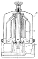
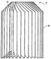
図1及び図2には、一部材とされた螺旋状ベーンのモジュール21を有する自動駆動式遠心分離機20を示す。この螺旋状ベーンのモジュール21は、米国特許第5,575,912号、米国特許第5,637,217号、米国特許第6,017,300号、米国特許第6,019,717号に開示されているような従来設計における円錐形分離板の積重体を含む組立体から置き換えられるものである。
【0014】
遠心分離機20の全体的な容器及び構造の大部分は、上記で引用した2つの米国特許に開示されたものと同一である。顕著に相違する点は、従来技術の円錐形分離板の積重体を含む組立体が、本発明の螺旋状ベーンのモジュール21に置き換えられた点である。図6における一部ずつを並べた比較に示すように、螺旋状ベーンのモジュール21に適合するための、他の細かな構造上の変更もなされる。
【0015】
遠心分離機20は、米国特許第5,575,912号及び米国特許第5,637,217号に記載されたものと極めて類似した方法で作動するもので、典型的には油である流入液体を、支持ベース(図示せず)毎に設けられた入口開口部を通して受け入れるものである。この支持ベースに設けられた接続通路は、ロータハブの中空内部に液体が流入することを許容する。本明細書においては、ロータハブを支承管22とも呼ぶ。液体は、その後、管頂部の開口23に達するまで、上方に向けて流れる。管22上側の外周面上には、典型的には、等間隔に隔てられた4つの開口23が設けらている。液体は、これらの開口23を通って流出し、螺旋状ベーンのモジュール21近傍に至ると、半径方向外方に流れる。ライナー24の上側部分は、加速用ベーン25と一体に形成される。加速用ベーン25は、ライナー24の上側部分と共に、流路(隣接する加速用ベーン間に形成される通路)を形成する。これらの加速用ベーン25は、典型的には、4つ、6つ又は8つが等間隔で配置され、油(又はその他の液体)が半径方向外方に流れることを容易にし、この液体の流れを、螺旋状ベーンのモジュール21の頂部板27内に成形された入口穴26地点まで送る。ライナー24は、ベース29に組み立てられた殻体28により包み込まれている。液体は入口穴26に入り、螺旋状ベーンのモジュール21を通って流れ、最終的にモジュール21の下端縁31から流出する。この場合、流れは、支持基部板33と支承管22即ちロータハブの外面との間の環状の隙間部32を通って流れる。この流出流は、2つのジェットオリフィス34(断面図では一方のみが図示される)まで流れ続ける。これら2つのジェットオリフィスは、接線方向を向いた2つのジェットノズルとしての内側開口部に相当する。ノズルであるオリフィスの各々から流出する高速ジェットは、反作用であるトルクを発生させる。このトルクは、、液体が螺旋状ベーンのモジュール21を通って流れるときに螺旋状ベーンのモジュール内で粒子が分離され得るために十分な3000乃至6000rpmという高速度で、遠心分離機20を駆動する(回転させる)。具体的な流路を含む遠心分離機20を通る液体の流れ及び遠心分離機20の自己駆動のための流出液体の使用は、螺旋状ベーンのモジュール21内で生じる作用及び米国特許第5,575,912号と米国特許第5,637,217号に記載された円錐形分離板の積重体を含む組立体の構造と著しく異なるモジュール21の構造という重要な相違点を除けば、米国特許第5,575,912号、米国特許第5,637,217号、米国特許第6,017,300号、米国特許第6,019,717号に開示されたものと基本的に同一である。
【0016】
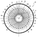
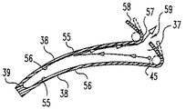
図1及び図2を更に参照すると分かるように、螺旋状ベーンのモジュール21は、ライナー24内の、従来技術の円錐形分離板の積重体を含む組立体が占めていた位置と基本的に同一の位置に配置される。このモジュール21は、頂部板27と、同一形態とされ且つ等間隔(間隙37を参照)に配置された一連の螺旋状ベーン38とを有している。「等間隔で配置された」という概念は、単に螺旋状ベーン間の一様なパターンを意味するもので、隣接するベーンにより形成される空間即ち間隙が半径方向にわたって一様であることを意味するものではない。隣接するベーン38間の空間又は間隙37は、内側ハブ部分39地点から最外周端縁40に向けて半径方向外側に行くにしたがって、漸進的に大きくなる(すなわち、周方向に広くなる)。
【0017】
螺旋状ベーンのモジュール21の全体は、一体の単一部材として、プラスチックから成形されている。個々のベーン38は、内側端縁に沿って、中央管即ちハブ部分39に結合されている。このハブ部分は、遠心分離機の支承管即ちロータハブ22上に、摺動して嵌め込まれる形状となっている。ハブ部分39の内径41をロータハブの外径に対して適切な寸法とすることにより、小さな公差で同軸上の嵌合をなすことができる。これは、遠心分離機の回転速度のために必要とされる全体的な重量バランスを得るのに寄与する。
【0018】
螺旋状ベーンのモジュール21は、環状形態のもので、略円筒形状となるように配置された個々の螺旋状ベーン38(合計34個)を備えている。ハブ部分39は、円筒状に成形されている。頂部板27は、略円錐形状のものであるが、中空の内部42を取り囲む略平坦な環状のリング部分27aを有している。この頂部板27の形状としては、半球状の上面を有するようにすることも考えられる。また、モジュール21の一部として、頂部板27の外周端縁43に隣接して分割板44が備えられる。分割板44は、リング形状のもので、半径方向外側に向けて水平に延び出している。また、頂部板27には複数の入口穴26が成形されている。これらの入口穴26は、頂部板の外周端縁43に隣接して、また分割板44が開始する位置に隣接して、配置されている。図2の断面図において、入口穴26及び分割板44は、実際には切断面2−2の上方にあるため、破線で示されている。この破線は、これらの部分のベーン38に対する位置を図示するものである。
【0019】
管の開口23から流出して入口穴26の方向に流れる液体の流れは、実際には、入口穴26に対して(半径方向に)対応する位置にある加速用ベーン25によって、「落とされる」。流れは、これらの入口穴から頂部板27を通り抜けて流れる。この場合、隣接する螺旋状ベーン38の各対間の分離処理用の間隙37の各々に、一つの入口穴が対応している。流れが入口穴を通って各間隙37内に流れ込むと、流れの出口がロータハブの外面と基部板の内側端縁との間にあるため、この流れは、半径方向内方、軸方向下方に向けて間隙内を通り抜ける。この流れの力学は、管の開口23から流出する流れが頂部板の表面を横切って均等に分配され、これにより34個の入口穴26に均等に分配されるようなものである。上述したように、各間隙には1つの入口穴が対応し、各ベーン38には1つの間隙が対応する。液体の流れが外側の広い地点からロータハブに隣接する内側の狭い地点に向けて間隙37を通り抜けるとき、遠心分離機の高速回転に起因する遠心力が、重い粒状物質に作用する。これにより、重い粒状物質は、螺旋状ベーンの凹型面に集められながら、半径方向外側に徐々に移動し、さらに外方に滑り続け、最終的にモジュールから流れ出して、モジュール21外周端縁とライナー殻体24内面との間のスラッジ捕集領域内に蓄積することができる。粒子45の1つの可能な経路が、図5に概略的に図示されている。
【0020】
分割板44は、入口穴26付近からライナー24の内面48に接触しない内面48の近傍まで、半径方向外側に延び出している。分割板44は、流れが入口穴26の周りを迂回して流れることによりスラッジ(即ち、分離された粒状物質及び油)が捕集される静止領域50を攪乱するのを防止する。本発明の設計は、流れが静止領域50を攪乱するのを防止することにより、流動液体から既に分離された粒状物質の再混入を大幅に抑制できる。再混入の概念には、液体の流れから既に分離された粒状物質の一部を解き放ち又は拾い上げ、これらの粒状物質が液体内に戻ることを許容し、これにより既に行われた処理を無効にしてしまうことを含む。なお、分割板44とライナー24の内面48と離間距離は、加速用ベーン25の領域内で分離される大きな粒状物質が静止領域50内に排出され得る程度に大きなものとされる。
【0021】
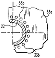
液体の流れは、入口穴26を通過して、分離処理がなされる間隙37に流入すると、この間隙内に広がり、半径方向内方かつ軸方向下方に進み、下方端縁31に至り、ここから隙間部32を通って流出する。この流れは、間隙37を通る予定された流れから迂回してしまうことを、基部板33の使用により防止される。この基部板は、隙間部32における開口を除く他のいかなる出口経路をも遮断するものである。ここで、隙間部は、基部板33の内側円形端縁51と、支承管22の外面52即ちロータハブ(図1A参照)との間に形成されるものである。
【0022】
本発明の1つの代替的な実施の形態(図1B参照)においては、基部板33aは、支承管22と接触するところまで延びて、隙間部32が閉止されている。流路となるように、複数の隙間穴33bが、隙間部32と略同一の位置となるように、基部板33aに形成されている。簡単のため、個々ののベーン38は図1A及び図1Bの断面図から省略されている。円形の穴33bに代えて、実質的に任意の型式の開口部を用いることができる。このような開口部としては、半径方向及び(又は)周方向のスロットが用いられ得る。
【0023】
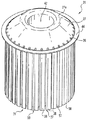
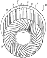
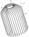
図3、図4及び図5を参照すると、螺旋状ベーンのモジュール21の詳細な構造が図示されている。図3及び図4は、モジュール21の一部材に成形された形状の斜視図である。図5は、一対の螺旋状ベーン38と、この螺旋状ベーンの間に形成された間隙37とを概略的に示す頂面図である。流路と関連して一部説明したように、螺旋状ベーンのモジュール21は、34個の螺旋状ベーン38を含むものである。これら各ベーンは、実質的に同一の構造を持ち、一部材に成形されたモジュールとなるように一体に接続されている。これら34個の螺旋状ベーン38の各々は、一部材である構造体の一部として、頂部端縁において、頂部板27の下側又は下側面に一体に接続されている。螺旋状ベーン38の各々は、頂部板から軸方向に、対応する下側端縁31に向けて延び出している。各ベーンの内側端縁は、一緒になって、内側ハブ部分39を形成している。各螺旋状ベーン38は、凸型外面55と、凹型内面56とを有している。これらの面は、約1.0mm(0.04インチ)の実質的に均一な厚さの螺旋状ベーンを形作る。1つのベーンの凸型面55と、隣接するベーンの凹型面56は、2つのベーンの間に、それぞれ間隙37を形作る。ベーン間の間隙の幅すなわち周方向の厚みは、ベーンの外側に行くしたがって大きくなっている。
【0024】
各螺旋状ベーン38は、内側ハブ部分39から半径方向外方に行くにしたがって、湾曲し(湾曲部分57)、対応する入口穴26の一部を取り囲む。部分57は、入口穴から離れる側に接線に沿って延び、乱流防止部58を形成する。1つの螺旋状ベーン38の乱流防止部58は、頂面図から見て反時計回り方向に、隣接するベーンに向けて、周方向に延び出している。1つのベーンの乱流防止部58の自由端即ち端縁と、隣接する螺旋状ベーンの湾曲部分57との間には、分離間隙59が形成される。この分離間隙は、実質上、軸方向の、即ち全長のスリットであり、周方向への幅は約1.8mm(0.07インチ)である。各乱流防止部58の小さな湾曲は、交互に並ぶ分離間隙59と共に、略円筒形状を形成する。この円筒形状は、頂部板27の下方に配置される螺旋状ベーンのモジュール21の最も外側の側面を形作る。
【0025】
各螺旋状ベーンの内側端縁から外側の湾曲部分57に至るまでの湾曲形状は、特徴的な幾何学的形態を有している。遠心分離機の軸方向回転中心線60aから34個の螺旋状ベーン38の任意の1つの上の交差点61まで引いた線60は、この交差点における螺旋状ベーンの湾曲に対する接線62に対し、45゜の内角60bを有する(図2)。この特徴的な幾何学的形態は、各螺旋状ベーンの主要部分の凸型部分及び凹型部分には当てはまるが、湾曲部分57又は乱流防止部58の何れにも当てはまらない。好ましい実施の形態においては45゜である内角は、螺旋状ベーンのモジュール及び対応する遠心分離機に対する螺旋状ベーンの角度と呼び得る。この内角の好ましい範囲は、30゜から60゜であると考えられる。先に引用した米国特許第5,575,912号及び米国特許第5,637,217号は、各円錐体の円錐壁の勾配即ち傾斜に基づいて、典型的には45゜である円錐体の角度を定義していたが、本発明では、螺旋状ベーンの角度を定義する。
【0026】
流れが間隙37を通過する過程において、分離されるべき粒状物質は、半径方向の遠心力成分の作用により、外側に向かう略半径方向の流路に沿って間隙を通過し、隣接するベーン間の間隙を通り抜ける。この粒状物質は、実際には、上述した米国特許第5,575,912号及び米国特許第5,637,217号の円錐形分離板の積重体を含む組立体の形状の場合におけるのと同様に、流れを遡る方向に向けて流れる。液体の流れから分離されるべき粒状物質を構成する粒子が、いったん、対応するベーンの凹型の内側螺旋状面に到着すると(図5参照)、流体の境界層における流れ速度の不存在により、これらの粒子は半径方向外方に移動していく。この半径方向外方の経路は、スラッジ捕集部分すなわち静止領域50に向かうものである。粒子は、その後、螺旋状ベーンの周方向に不連続な乱流防止部(すなわち分離間隙59)の間に形成された軸方向に連続するスリットを通って、螺旋状ベーンのモジュールから「脱落する」。上述したように、乱流防止部の機能は、間隙37内で生ずる流れとスラッジの捕集領域(静止領域50)との間の流体の相互作用を減少させることである。なお、スラッジ捕集領域を「静止領域」と称しているが、この用語は、好ましい状態を表わすものに過ぎない。理想的には、このスラッジ捕集領域50は、完全に静止しており、その結果、実質的に乱流が存在せず、いかなる粒状物質も液体の流れ中に再混入する恐れがないようにするのがよい。本実施形態では、乱流防止部58は、頂面側から見て、円形の輪郭を形作るように構成されている。しかしながら、本発明においては、これらの各乱流防止部58は、外側に向けてわずかに傾かせ、これにより、各乱流防止部の内面に集められるであろう粒状物質も捕集領域に「滑り出す」ことができるようにしてもよい。各螺旋状ベーンの湾曲部分の位置には、隅部が形成されるので、一部の粒状物質がその隅部内に蓄積しがちとなる。乱流防止部を傾かせることにより、この隅部を広げ、集められた粒状物質がスラッジ捕集領域(静止領域50)内に滑り出やすくすることができる。この代替的な乱流防止部部分の形状は、図5に破線で示されている。
【0027】
流れは、隣接する螺旋状ベーンの間の間隙を後にして、ロータハブに隣接する隙間部から流出した後、ジェットノズルに達し、このジェットノズルから高速度で放出される。この結果、反力によって、ロータが高速度で回転する。この形態の1つの代替例として、ロータは、このロータが取り付けられた衝動タービンによって駆動してもよい。更に、成形された螺旋状ベーンのモジュールは、米国特許第5,637,217号に開示されたものと同様に、スラッジを保持するライナー殻体と基部板の組立体内部に「包み込まれる」。この独特の形態は、遠心分離機のロータの保守を迅速かつ容易に行うことを可能とする。これは、スラッジが内側カプセル内に完全に保持され、解体又は洗浄が全く不要となるからである。また、この代わりに、本発明の螺旋状ベーンのモジュールを、完全に使い捨て型の遠心分離機用ロータの部品である円錐形分離板の積重体を含む組立体と置き換えることもできる。
【0028】
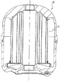
図6は、遠心分離機63の左側半分の典型的な従来技術の円錐形分離板の積重体を含む組立体64と、右側半分の本発明による螺旋状ベーンのモジュール21を、横に並べた概略図である。図6は、本発明の螺旋状ベーンのモジュール21は、米国特許第5,575,912号、米国特許第5,637,217号、米国特許第6,017,300号、米国特許第6,019,717号に記載された従来技術の円錐形分離板の積重体を含む組立体と置き換えることができることを示した上記説明を、より一層明確にすることを目的とするものである。対応する基部板65、33の形状は、2つの型の間でわずかに異なっているが、遠心分離機の構造の残りの部分は、これらの型の間で実質的に同一である。
【0029】
図7A、図7B及び図7Cには、螺旋状ベーンのモジュールの一部分として使用される螺旋状ベーンの形式の3つの代替形態を示す。これらの代替形態の一つ一つは従来技術の円錐形分離板の積重体を含む組立体を螺旋状ベーンのモジュールに置き換えるという着想を維持しながら、本発明と同一の理論及び作用の中で利用され得る。
【0030】
図7Aでは、モジュール21の湾曲した螺旋状ベーン38は、実質的に平坦な平面状表面を有するベーン68と置き換えられている。ベーン68は、正確に半径方向にではないが、外方に延びるように、ずらした状態で配置されている。図7Aの頂面図には、合計24個のベーン即ち平板68が図示されているが、実際の数は、遠心分離機の全体寸法や、液体の粘度や、分離すべき粒子の大きさに対して要求される効率のような変数に基づいて、増減が可能である。各板の傾斜角度(α)すなわち勾配も別の変数である。各板68は半径方向に対して同一の角度(α)に設定されるが、この角度の選択は変更可能である。角度の選択は、一部分、遠心分離機の回転速度に依存する。
【0031】
図7Bでは、個々のベーン69は、ベーン38と同様に湾曲しているが、より大きな湾曲形状即ち凹型となっている。更に、各ベーン69は、支承管22から離れた地点に至るにしたがって、湾曲が徐々に大きくなっている。このようなベーンの形状を「超螺旋状」と呼び、この「超螺旋状」を幾何学的に次のように定義する。まず、モジュール21の軸方向中心線でもある支承管22の軸方向中心線から半径方向の線72を引く。この線は、1つのベーンの凸型面上と、点73で交差する。この交差点73における接線74は、半径方向の線72との間に内角75を持つ。この内角75の大きさは、交差点73が支承管22から離れるにしたがって大きくなる。この螺旋状ベーンの実施の形態における理論は、回転軸からの距離に比例して慣性力が増大したときに粒子の滑り速度が一定となるように、各ベーンを形作るものである。各ベーン69の湾曲形状を除けば、図7Bの概略図に示した螺旋状ベーンのモジュールは、螺旋状ベーンのモジュール21と同一である。
【0032】
図7Cでは、モジュールにおける螺旋状ベーンの形状は、図7Bのベーン69の形状を基本として、一部分が短縮されたベーン70を加えたものである。完全な長さのベーン69の各対の間に、それぞれ、短縮されたベーン70が配置される。各短縮されたベーンの寸法、形状及び配置は、モジュールの全体にわたって同一である。これらの短縮されたベーン70は、ハブの内径において密集して配置されることによりベーンの数及びベーンの間隔が制限される場合にベーンの全表面積を増し得るようにターボ過給機コンプレッサ内で使用されるものと同様である。
【0033】
本発明における他の設計上の変更としては、製造及び成形方法の変更がある。例えば、ベーン(又は板)の略円筒形状を、一繋がりの部材として押し出し成形し、その後、所望の軸方向の長さ即ち高さに切断し、別個に製造(典型的には成形)された頂部板に組み付けることもできる。頂部板は、モジュール21の構成要素として前に説明したように、所望の入口穴及び分割板を有するように成形される。
【0034】
本発明における他の設計上の変更として考えられるものは、螺旋状ベーンのモジュールを2つの部分、即ち、頂部側の部分と底部側の部分に分割することである。この製造技術は、ベーンとベーンの間隔が狭いことに起因する成形上の困難を回避するために使用され得る。2つの部分を製造した後、これらを一体のモジュールとなるように接続する。この場合、頂部板をベーンの組立体の頂部側部分と一緒に成形し、基部板をベーンの組立体の底部側部分一緒に成形することが考えられる。
【0035】
螺旋状ベーンのモジュール21及び/又は図7A、図7B及び図7Cの3つの代替となる(螺旋状)ベーン型式は、図8及び図8Aに図示するように、衝動タービン駆動式の遠心分離機80と組み合わせて使用することができる。以下の説明では、螺旋状ベーンのモジュール21を組み合わせた場合を説明する。図8Aには、衝動タービン装置81を概略図で示す。
【0036】
螺旋状ベーンのモジュール21及び/又は図7A、図7B及び図7Cの3つの代替となる(螺旋状)のベーン型式の一つは、遠心分離機に使用される使い捨て型ロータ82の一部分とされ得る。図9には、螺旋状ベーンのモジュール21が含まれている。図9の使い捨て型ロータ82は、遠心分離機80のような衝動タービン駆動型遠心分離機と組み合わせて使用することもできると考えられる。
【0037】
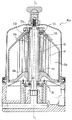
衝動タービン装置81を備えた衝動タービン駆動型遠心分離機80を、図10に概略的に示す。遠心分離機80aには、本発明の他の実施形態と同様に、螺旋状ベーンのモジュール91が組み込まれている。なお、螺旋状ベーンのモジュール91は、他の型式の遠心分離機にも使用し得る。上記実施形態の遠心分離機と同様に、遠心分離機80aは、多数の管頂部側の開口23aを有する支承管22aを備える。作動中、管頂部側の開口23aから、螺旋状ベーンのモジュール91に作動流体が供給される。
【0038】
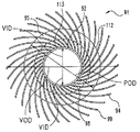
図11から図14に示すように、螺旋状ベーンのモジュール91は、中央管即ちハブ部分92と、多数のベーン94と、頂部板95とを備える。図11に示すように、中央管92は、遠心分離機80aの回転中心軸Lに沿って延びている。ベーン94は、中央管92から半径方向外側に延び、また回転中心軸Lに沿って延びている。図14に示すように、各ベーン94の半径方向の内側端縁98は、中央管92に取り付けられており、半径方向の外側縁99は、中央管92から離れる方向に延び出している。複数のベーン94の内側端縁98は、ベーン内側径VIDを形作る。また、複数のベーン94の外側縁99は、ベーン外側径VODを形作る。一実施形態では、中央管92とベーン94と頂部板95は、一体に成形され、螺旋状ベーンのモジュール91は一部材となっている。ベーン94は、図示の実施形態では螺旋形状をしているが、例えば上記した図7A〜Cのような他の形状のものとすることもできる。
【0039】
図11に示すように、頂部板95は、中央管92の第1の(入口側の)端部分100に取り付けられている。中央管92の第1の端部分100と反対側端部は、第2の(出口側の)端部分101である。本実施形態では、中央管92の小部分102が頂部板95の上方に延び出しているが、頂部板95は中央管92の上端103と同一平面にあるようにしてもよい。図10に示すように、中央管92はベーン94の全長にわたって延びているわけではない。そして、中央管92の第1の端部分100においては、中央管92の上端部103とベーン94の内側端縁98により、複数の流体入口通路106が形成されている。同様に、第2の端部分101においては、中央管の下側端部102とベーン94の内側端縁98により、複数の流体出口通路107が形成されている。流体入口通路106においては、ベーン94の上側部分108は、頂部板95を貫通して上方に延び出している。遠心分離機80aの作動中、ベーン94の上側部分108は、頂部板95に沿って流体が滑ることを防止する。
【0040】
図11に示すように、頂部板95は、内側の平坦部分110と、外側の傾斜部分111と、外周端縁112と、中央管92に取り付けられた内周縁113とを備えている。(サブミクロンの)超微粒子の捕集の保持は、ロータの回転に対する流体速度が最小化されたときに達成される。遠心分離機80aのスラッジ捕集領域50a(図10参照)における最小の平均相対速度は、頂部板95の外側縁112が、ベーン内側径VIDとベーン外側径VOD(図14参照)間の距離の約1/4から3/4の間に配置されたときに得られる。特に、頂部板95の外側径PODがベーン内側径VIDとベーン外側径VODの中間地点にあるときにスラッジ捕集領域50aの平均相対速度が最小化される。言い換えれば、頂部板95の最適な径は、略ベーン内側径VIDとベーン外側径VODの平均値であり、この場合、頂部板95の外側縁112は、中央回転軸Lから半径方向に沿って計ったベーン94の長さの半分の地点にある。例えば、螺旋状ベーンの内側径VIDが約5cm(2インチ)で、螺旋状ベーンの外側径VODが約12.5cm(5インチ)である場合には、頂部板95の最適の径は、約8.75cm(3.5インチ)となる((12.5−5)/2=8.75)。図11には、この関係を他の観点から図示している。ここでは、頂部板95の幅PWは、ベーン94の幅VWの半分となっている。
【0041】
図15の流体解析(CFD:computational fluid dynamics)のグラフ114には、頂部板95の外側径をベーン94の内側径VIDと外側径VODの間に配置した効果が示される。このグラフ114は、隣接するベーン94間の流体通路内における流体速度勾配115を、3つの異なる条件毎に示す。これらの流体速度勾配115は、ロータの軸方向の中間地点(即ち、頂部板95と底部の出口との中間地点)における、中央回転軸Lに垂直な断面におけるものである。グラフ114において、グラフ部分120は、遠心分離機80a内に頂部板95を備えなかった場合の速度勾配115の分布を示す。また、グラフ部分121は、頂部板95の外側径PODがベーン内側径VIDとベーン外側径VODの略半分である場合の速度勾配115の分布を示す。また、グラフ部分122は、頂部板95の外側径PODがベーン外側径VODと等しい場合の速度勾配115の分布を示す。
【0042】
グラフ部分121と比較すると、頂部板95がない場合と、頂部板95がベーン94全体を覆う場合は、いずれも多数の速度勾配115が存在していることが分かる。頂部板95がない場合(グラフ部分121)、流路の軸方向全体にわたる相対速度の体積平均は、0.023m/secである。図示の実施形態では、螺旋状ベーンのモジュール91は反時計回転方向に回転し、この結果、圧力面124が、各ベーン94の回転方向を向く表面に形成される。グラフ部分120に示されるように、頂部面95がない場合、圧力面124には、多数の速度勾配が存在する。なお、螺旋状ベーンのモジュール91は、時計回転方向に回転するようにしてもよい。頂部板95の外側径PODがベーン外側径VODと等しい場合(グラフ部分122)、相対速度の体積平均は、0.021m/secである。グラフ部分122に示されるように、多数の速度勾配115が、頂部板95が終端となる地点であるベーン94の外側端部99付近に生じる。頂部板95の外側径PODがベーン内側径VIDとベーン外側径VODの半分である場合(グラフ部分121)、速度勾配115の数は、ベーン94の圧力面124及び外側端部99付近のいずれにおいても減少している。この設計によれば、流体の平均速度は、0.006m/secまで最小化される。この流体速度の全体的な減少により、超微粒子の捕集能力が高められる。
【0043】
なお、上記実施形態において、本発明を詳細に説明してきたが、これは例示であって本発明の範囲を制限するものではない。
【図面の簡単な説明】
【図1】本発明の典型的実施形態における自己駆動型遠心分離機を正面から見た全断面図である。
【図1A】図1の1A−1A線から見た遠心分離機の部分断面図である。
【図1B】本発明の他の実施形態における遠心分離機を、図1の1A−1A線に対応する線から見た部分断面図である。
【図2】図1の2−2線から見た遠心分離機の全断面図である。
【図3】図1の遠心分離機に含まれる螺旋状ベーンのモジュールを示す斜視図である。
【図4】図3の螺旋状ベーンのモジュールを底面側から見た斜視図である。
【図5】図3の螺旋状ベーンのモジュール内の二つの螺旋状ベーン及び流路を示す図である。
【図6】従来技術における円錐状分離板の積重体と、本発明による図3の螺旋状ベーンのモジュールとを、左右に並べて比較した断面図である。
【図7A】本発明におけるベーンの一代替形態を示す平面図である。
【図7B】本発明におけるベーンの他の代替形態を示す平面図である。
【図7C】本発明におけるベーンの更に他の代替形態を示す平面図である。
【図8】本発明の更に他の実施形態における衝動タービン駆動式遠心分離機を正面から見た全断面図である。
【図8A】図8の遠心分離機における衝動タービン装置を示す平面図である。
【図9】本発明の更に他の実施形態における使い捨て型ロータを正面から見た全断面図である。
【図10】本発明の更に他の実施形態における衝動タービン駆動式遠心分離機を正面から見た全断面図である。
【図11】図10の遠心分離機に用いられる螺旋状ベーンのモジュールを正面から見た全断面図である。
【図12】図11の螺旋状ベーンのモジュールの正面図である。
【図13】図11の螺旋状ベーンのモジュールの斜視図である。
【図14】図11の螺旋状ベーンのモジュールの平面図である。
【図15】3種類の異なる設計における相対流体速度を、流体解析により算出した図である。
【符号の説明】
20 自己駆動式遠心分離機
21 螺旋状ベーンのモジュール
22 支承管(ロータハブ)
23 開口
27 頂部板
28 殻体
29 ベース
32 環状の隙間部
33 支持基部板
34 ジェットオリフィス
37 間隙
38 螺旋状ベーン
39 ハブ部分(中央管)
44 分割板
58 乱流防止部
59 間隙
68 ベーン(平板)
69 超螺旋形状のベーン
70 短縮されたベーン
72 半径方向の線
73 交差点
74 接線
91 螺旋状ベーンのモジュール
92 ハブ部分
94 ベーン
95 頂部板[0001]
BACKGROUND OF THE INVENTION
The present invention is broadly related to the continuous separation of particulates from fluids performed using a centrifugal field. More particularly, the present invention relates to the use of a spiral plate or vane in a centrifuge vessel with a suitable propulsion device for self-driven rotation of the spiral vane. In one embodiment of the present invention, a jet nozzle is used in the propulsion device. In other embodiments of the present invention, the specific shape and type of the spiral vane is modified to have a flat (planar) plate.
[0002]
[Prior art]
Since the use of helical vanes in the preferred embodiment of the present invention is a design change from the prior art that uses a stack of conical separator plates as the basis for the separation of particulates from the fluid, the product of the conical separator plates Examining the prior art using heavy bodies is useful in recognizing the differences between the present invention and the prior art and the benefits obtained by the present invention.
[0003]
US Pat. No. 5,575,912, issued to Herman et al. On November 19, 1996, discloses a centrifuge for a bypass circuit for separating particulate material from circulating liquid. . The configuration of the centrifuge includes a hollow and substantially cylindrical centrifuge container. This centrifuge container is combined with the base plate to form a chamber through which liquid flows. A hollow central tube is provided through the base plate in the axial direction and extends into the hollow container of the centrifuge container. The bypass circuit centrifuge is designed to be incorporated into the cover assembly, and a pair of tangential jet nozzles located on the opposite side of the base plate rotate the centrifuge in the cover. As a result, the particles are separated from the liquid. A plurality of conical separation plates are accommodated inside the centrifuge container. These conical separation plates are arranged in a row and are arranged close to each other so as to increase the separation efficiency. This stack of conical separator plates is sandwiched between a top plate disposed adjacent to the top of the centrifuge container and a bottom plate disposed near the base plate. The incoming liquid stream flows out of the central tube through the two oil inlets and from there through the top plate. The top plate, along with the ribs on the inner surface of the centrifuge container, accelerates this flow and directs it to the upper portion of the stack of conical separator plates. When this flow flows radially inward through a flow path formed between adjacent conical separator plates, the particles are separated. When the inner diameter of the conical separator plate is reached, this liquid continues to flow downwards towards the tangentially directed jet nozzle.
[0004]
US Pat. No. 5,637,217, issued to Herman et al. On June 10, 1997, is a continuation-in-part application from US Pat. No. 5,575,912. US Pat. No. 5,637,217 discloses a centrifuge for a bypass circuit for separating particulate matter from a circulating liquid. The configuration of the centrifuge includes a hollow and substantially cylindrical centrifuge container. This centrifuge container is combined with the base plate to form a chamber through which the liquid flows. A hollow central tube is provided through the base plate in the axial direction and extends into the hollow container of the centrifuge container. The bypass circuit centrifuge is designed to be incorporated into the cover assembly, and a pair of tangential jet nozzles located on the opposite side of the base plate rotate the centrifuge in the cover. As a result, the particles are separated from the liquid. A plurality of conical separation plates are accommodated inside the centrifuge container. The incoming liquid stream flows out of the central tube through the two oil inlets and from there through the top plate. In one embodiment, the top plate and ribs on the inner surface of the centrifuge container accelerate this flow and direct it to the upper portion of the stack of conical separator plates. In other embodiments, the row of stacks is part of a disposable assembly. In each embodiment, the particles are separated as the flow passes through the flow path formed between adjacent conical separator plates, after which the liquid is directed downwardly toward the tangentially directed jet nozzle. Continue to flow.
[0005]
US Pat. No. 6,017,300, issued to Herman et al. On January 25, 2000, discloses a centrifugal separation using a stack of conical separator plates to separate particulate matter from a circulating liquid. The machine is disclosed. The centrifuge configuration includes an assembly that includes a stack of conical separator plates. The assembly including the stack of conical separator plates forms a hollow rotor hub that rotates about its axis. The assembly including the stack of conical separator plates is attached to the shaft-type central tube. The shaft-type central tube is secured to the hollow base hub of the base assembly. The base assembly further includes a liquid inlet, a first flow path, and a second flow path communicating with the first flow path. The liquid inlet communicates with the base hub via the first flow path. A bearing device is arranged between the rotor hub and the shaft-type central tube for the rotational movement of the assembly including the stack of conical separator plates. The rotor hub is mounted with an impulsive turbine turntable. The fluid jet nozzle is arranged so as to face the turntable of the turbine. The fluid jet nozzle is in communication with the second fluid passage for directing the liquid fluid jet to the turbine turntable to provide rotational motion to the assembly including the stack of conical separator plates. The liquid to the fluid jet nozzle flows through the liquid inlet into a centrifuge using a stack of conical separator plates. The fluid inlet also receives fluid flowing through the stack of conical separator plates.
[0006]
US Pat. No. 6,019,717 issued to Herman on February 1, 2000 is a continuation-in-part from US Pat. No. 6,017,300. U.S. Pat. No. 6,019,717 is similar to the parent patent in addition to a honeycomb-like insert incorporated into a fluid jet nozzle to reduce turbulence at the inlet and improve turbine efficiency. The structure containing is disclosed.
[0007]
[Problems to be solved by the invention]
Improved separation efficiency obtained by the inventions of these US Pat. No. 5,575,912, US Pat. No. 5,637,217, US Pat. No. 6,017,300, US Pat. No. 6,019,717 Is due in part to a decrease in stacking distance, which is a gap between the conical separator plates. According to the idea of the present invention, a similar effect replaces an assembly containing a stack of conical separator plates with a radially spreading set of spiral vanes or plates having a uniform axial cross-sectional shape. It is theoretically concluded that The spiral vanes of the present invention are integrally joined to the central hub and top plate as will be described in the embodiments of the present invention described in detail below. In a preferred embodiment, the combination of these constituent parts is a combination that is integrally formed so as to be a single member. The top plate works with accelerating vanes on the inner surface of the liner shell and directs the flow coming out of the central part of the centrifuge towards the outer peripheral edge of the top plate where the inlet holes for flow are open. Send. A divider plate adjacent to the outer periphery of the top plate prevents the flow from diverting from the inlet holes, i.e., bypassing, and flowing into the spiral vane module from the gap between the outer peripheral vanes. If such a flow is allowed, turbulent flow may occur, and particles may be mixed again due to injection of particles into this region. In the form of each spiral vane in some embodiments, the outer peripheral edge of the top plate is a turbulence prevention part. This turbulence prevention section extends over the entire axial length of each helical vane, between the outer stationary sludge collection area and the gap between the helical vanes where the particles are separated from the liquid flow. This is a means for further reducing fluid interaction. The theoretical idea of this embodiment has resulted in an actual reduction in implementation. Initial testing was done to confirm the benefits and improvements gained by this first embodiment.
[0008]
Commercial implementation of the invention disclosed in US Pat. No. 5,575,912, US Pat. No. 5,637,217, US Pat. No. 6,017,300, US Pat. No. 6,019,717 In the form, an assembly comprising a stack of 20 to 50 conical separators is used. The individual conical separator plates are separately molded and stacked prior to assembly with the liner shell and base plate, or in the case of a disposable rotor design, with the hub or spool portion, Need to be aligned. This specific configuration increases the cost of equipment due to the large mold with multiple cavities and the assembly cost due to the time required to stack and align the individual conical separators separately. Cause and rise. The idea of the present invention “helical shaped in one piece” makes it possible to replace all the individual conical separator plates in the prior art with one molded component. The helical vanes that make up the one-piece module can be simultaneously injection molded with the hub portion of the module and the top plate described above. As an alternative to this, these individual spiral vanes may be extruded with a hub portion and then combined with a separately molded top plate. Even with this alternative method for the manufacturing method of the present invention, the total number of parts is reduced from between 20 and 50 separate parts to 2 parts.
[0009]
The present invention provides an alternative design to the technique using the stack of conical separator plates described above. Self-driven conical separation disclosed in US Pat. No. 5,575,912, US Pat. No. 5,637,217, US Pat. No. 6,017,300, US Pat. No. 6,019,717 The novelty and performance advantages of design with a stack of plates have been demonstrated in practical use. Some of these successful "secrets" of the prior art, namely the self-driven idea and the reduction in stacking spacing between the conical separators, are maintained in the present invention, but the basic design has changed. Has been. Replacing a vertically stacked stack of individually shaped conical separators with a one-piece spiral vane module is an important structural change and represents a new and unobvious advance in the art. It is thought that it shows.
[0010]
[Means for Solving the Problems]
In one embodiment of the present invention, a centrifuge for separating particulate matter from a liquid passing through a centrifuge includes a base and a centrifuge shell that is assembled to the base and forms a hollow internal space with the base. A hollow rotor hub having a rotation center axis and assembled to the base and extending through the hollow internal space, and an opening serving as a flow outlet formed between the hollow internal space and the hollow rotor hub A support plate; and a module of a separation processing vane that is arranged in the hollow interior space and is configured and arranged to extend around the hollow rotor hub supported by the support plate.
[0011]
One object of the present invention is to improve a self-driven centrifuge with a separation vane module.
[0012]
DETAILED DESCRIPTION OF THE INVENTION
To facilitate an understanding of the principles of the present invention, the following description will be made with reference to the embodiments shown in the drawings, and specific terms will be used for the description. However, this is not intended to limit the scope of the invention. Modifications and further modifications of the described apparatus and further applications of the described principles of the invention may be normally conceived by those skilled in the art.
[0013]
1 and 2 show a self-driven
[0014]
Most of the overall container and structure of the
[0015]
The
[0016]
As can be further seen with reference to FIGS. 1 and 2, the
[0017]
The entire
[0018]
The
[0019]
The liquid flow flowing out of the
[0020]
The dividing
[0021]
When the liquid flow passes through the
[0022]
In one alternative embodiment of the present invention (see FIG. 1B), the base plate 33a extends to contact the bearing
[0023]
Referring to FIGS. 3, 4 and 5, the detailed structure of the
[0024]
Each
[0025]
The curved shape from the inner edge of each helical vane to the outer
[0026]
In the process in which the flow passes through the
[0027]
The flow leaves the gap between adjacent spiral vanes, exits the gap adjacent to the rotor hub, then reaches the jet nozzle and is discharged from the jet nozzle at a high velocity. As a result, the rotor rotates at a high speed due to the reaction force. As one alternative to this configuration, the rotor may be driven by an impulse turbine to which the rotor is attached. Further, the molded spiral vane module is “wrapped” within the liner shell and base plate assembly holding sludge, similar to that disclosed in US Pat. No. 5,637,217. This unique configuration allows for quick and easy maintenance of the centrifuge rotor. This is because the sludge is completely retained in the inner capsule and no disassembly or cleaning is required. Alternatively, the spiral vane module of the present invention can be replaced with an assembly that includes a stack of conical separator plates that are part of a fully disposable centrifuge rotor.
[0028]
FIG. 6 shows an
[0029]
7A, 7B and 7C show three alternative forms of spiral vanes used as part of the spiral vane module. Each of these alternatives is within the same theory and operation as the present invention, while maintaining the idea of replacing the assembly containing the stack of prior art conical separator plates with a spiral vane module. Can be used.
[0030]
In FIG. 7A, the
[0031]
In FIG. 7B, the
[0032]
In FIG. 7C, the shape of the spiral vane in the module is the same as the shape of the
[0033]
Other design changes in the present invention include manufacturing and molding method changes. For example, a generally cylindrical shape of a vane (or plate) is extruded as a single piece, then cut to the desired axial length or height and manufactured separately (typically formed). It can also be assembled to the top plate. The top plate is shaped to have the desired inlet holes and divider plates as previously described as components of
[0034]
Another possible design change in the present invention is to divide the spiral vane module into two parts: a top part and a bottom part. This manufacturing technique can be used to avoid molding difficulties due to the narrow spacing between vanes. After the two parts are manufactured, they are connected to form an integral module. In this case, it is conceivable to mold the top plate together with the top side portion of the vane assembly and the base plate together with the bottom side portion of the vane assembly.
[0035]
The
[0036]
One of the
[0037]
An impulse turbine driven
[0038]
As shown in FIGS. 11-14, the
[0039]
As shown in FIG. 11, the
[0040]
As shown in FIG. 11, the
[0041]
The fluid analysis (CFD) graph 114 of FIG. 15 shows the effect of placing the outer diameter of the
[0042]
Compared to the graph portion 121, it can be seen that there are a large number of
[0043]
Although the present invention has been described in detail in the above embodiment, this is merely an example and does not limit the scope of the present invention.
[Brief description of the drawings]
FIG. 1 is a full sectional view of a self-driven centrifuge according to an exemplary embodiment of the present invention as viewed from the front.
1A is a partial cross-sectional view of a centrifuge as seen from line 1A-1A in FIG.
FIG. 1B is a partial cross-sectional view of a centrifuge according to another embodiment of the present invention, as viewed from a line corresponding to line 1A-1A in FIG.
2 is a full sectional view of the centrifuge as viewed from line 2-2 in FIG. 1. FIG.
FIG. 3 is a perspective view showing a spiral vane module included in the centrifuge of FIG. 1;
4 is a perspective view of the spiral vane module of FIG. 3 as viewed from the bottom side.
FIG. 5 shows two spiral vanes and flow paths in the spiral vane module of FIG. 3;
6 is a cross-sectional view comparing a stack of conical separation plates in the prior art and the spiral vane module of FIG. 3 according to the present invention side by side.
FIG. 7A is a plan view showing an alternative form of vane in the present invention.
FIG. 7B is a plan view showing another alternative form of vane in the present invention.
FIG. 7C is a plan view showing still another alternative form of the vane according to the present invention.
FIG. 8 is a full sectional view of an impulse turbine-driven centrifuge according to still another embodiment of the present invention as seen from the front.
8A is a plan view showing an impulse turbine device in the centrifuge of FIG. 8. FIG.
FIG. 9 is a full sectional view of a disposable rotor according to still another embodiment of the present invention as viewed from the front.
FIG. 10 is a full sectional view of an impulse turbine driven centrifuge according to still another embodiment of the present invention as seen from the front.
11 is a full cross-sectional view of a spiral vane module used in the centrifuge of FIG. 10 as viewed from the front.
12 is a front view of the spiral vane module of FIG. 11. FIG.
13 is a perspective view of the spiral vane module of FIG. 11. FIG.
14 is a plan view of the spiral vane module of FIG. 11. FIG.
FIG. 15 is a diagram in which relative fluid velocities in three different designs are calculated by fluid analysis.
[Explanation of symbols]
20 Self-driven centrifuge
21 Spiral vane module
22 Bearing pipe (rotor hub)
23 Opening
27 Top plate
28 Shell
29 base
32 Annular gap
33 Support base plate
34 Jet orifice
37 gap
38 Spiral Vane
39 Hub part (central pipe)
44 division board
58 Turbulence prevention unit
59 Gap
68 Vane (flat plate)
69 Super spiral shaped vane
70 shortened vanes
72 Radial line
73 Intersection
74 Tangent
91 Spiral vane module
92 Hub part
94 Vane
95 Top plate
Claims (34)
回転中心軸を有する分離処理用のベーンのモジュールを備え、
この分離処理用のベーンのモジュールに、
前記回転中心軸に沿って延びるハブ部分と、
前記ハブ部分の一端に配置された板と、
前記ハブ部分に接続する半径方向の内側端縁を有し、前記ハブ部分から半径方向外側に延びる複数のベーンと、
を備え、
前記複数のベーンは、前記板を貫通して、前記板の両面から前記回転中心軸に沿った方向に延びており、これにより、前記複数のベーンは、前記板と一体となっており、
前記板の外周端縁は、前記ハブ部分と前記複数のベーンの外側縁との間に位置する遠心分離機。In the centrifuge
A separation vane module having a central axis of rotation;
In this separation processing vane module,
A hub portion extending along the rotational axis;
A plate disposed at one end of the hub portion;
Has a radial inner edge to be connected to the hub portion, a plurality of vanes Ru extending radially outwardly from said hub portion,
With
The plurality of vanes extend through the plate in a direction along the rotation center axis from both surfaces of the plate, whereby the plurality of vanes are integrated with the plate,
An outer peripheral edge of the plate is a centrifuge located between the hub portion and outer edges of the plurality of vanes.
回転中心軸を有する分離処理用のベーンのモジュールを備え、
この分離処理用のベーンのモジュールに、
前記回転中心軸に沿って延びるハブ部分と、
前記ハブ部分から半径方向外側に延びる複数のベーンと、
前記ハブ部分の周りに配置された板と
を備え、
前記複数のベーンは、前記板を貫通して、前記板の両面から前記回転中心軸に沿った方向に延びており、これにより、前記複数のベーンは、前記板と一体となっており、
前記複数のベーンの各々は、前記回転中心軸に対する周方向に延びて粒子の再混入を防止するための乱流防止部を形成する外側縁を有しており、
前記板は、前記ハブ部分と前記複数のベーンの外側縁との間に位置する外周端縁を備えた遠心分離機。In the centrifuge
A separation vane module having a central axis of rotation;
In this separation processing vane module,
A hub portion extending along the rotational axis;
A plurality of vanes Ru extending radially outwardly from said hub portion,
Comprising a plate disposed around the hub portion,
The plurality of vanes extend through the plate in a direction along the rotation center axis from both surfaces of the plate, whereby the plurality of vanes are integrated with the plate,
Each of the plurality of vanes has an outer edge that extends in a circumferential direction with respect to the rotation center axis and forms a turbulent flow prevention portion for preventing re-mixing of particles,
The centrifuge includes a peripheral edge located between the hub portion and the outer edges of the plurality of vanes.
回転中心軸を有する分離処理用のベーンのモジュールを備え、
この分離処理用のベーンのモジュールに、
前記回転中心軸に沿って延びるハブ部分と、
前記ハブ部分から半径方向外側に延び、前記回転中心軸に沿って延びる複数の湾曲したベーンと、
前記ハブ部分の周りに配置された板と
を備え、
前記複数のベーンは、前記板を貫通して、前記板の両面から前記回転中心軸に沿った方向に延びており、これにより、前記複数のベーンは、前記板と一体となっており、
前記複数のベーンの各々は、前記回転中心軸から半径方向に延びる線とこの半径方向に延びる線が前記複数のベーンの一つと交差する交差点におけるベーンの接線がなす角度が前記交差点が前記ハブ部分から遠ざかるにしたがって大きくなる超螺旋形状を有し、
前記板は、前記ハブ部分と前記複数のベーンの外側縁との間に位置する外周端縁を備えた遠心分離機。In the centrifuge
A separation vane module having a central axis of rotation;
In this separation processing vane module,
A hub portion extending along the rotational axis;
A plurality of curved vanes extending radially outward from the hub portion and extending along the central axis of rotation;
Comprising a plate disposed around the hub portion,
The plurality of vanes extend through the plate in a direction along the rotation center axis from both surfaces of the plate, whereby the plurality of vanes are integrated with the plate,
Each of the plurality of vanes has an angle formed by a line extending in a radial direction from the rotation center axis and a tangent of the vane at an intersection where the line extending in the radial direction intersects one of the plurality of vanes. It has a super spiral shape that grows as you move away from it,
The centrifuge includes a peripheral edge located between the hub portion and the outer edges of the plurality of vanes.
回転中心軸を有する分離処理用のベーンのモジュールを備え、
この分離処理用のベーンのモジュールに、
前記回転中心軸に沿って延びるハブ部分と、
前記ハブ部分の一端に備えられた板と、
前記ハブ部分に接続された半径方向内側端縁と半径方向外周端縁とを有し、前記ハブ部分から半径方向外側に延び、前記回転中心軸に沿って延びる複数のベーンと、
を備え、
前記複数のベーンは、前記板を貫通して、前記板の両面から前記回転中心軸に沿った方向に延びており、これにより、前記複数のベーンは、前記板と一体となっており、
前記板の外周端縁が、前記ハブ部分と前記複数のベーンの外側縁の間隔の1/4から3/4の間に位置するようにした遠心分離機。In the centrifuge
A separation vane module having a central axis of rotation;
In this separation processing vane module,
A hub portion extending along the rotational axis;
A plate provided at one end of the hub portion;
A plurality of vanes having a radially inner edge and a radially outer edge connected to the hub portion, extending radially outward from the hub portion and extending along the central axis of rotation;
With
The plurality of vanes extend through the plate in a direction along the rotation center axis from both surfaces of the plate, whereby the plurality of vanes are integrated with the plate,
A centrifuge in which an outer peripheral edge of the plate is located between ¼ and ¾ of an interval between an outer edge of the hub portion and the plurality of vanes.
Applications Claiming Priority (2)
| Application Number | Priority Date | Filing Date | Title |
|---|---|---|---|
| US10/028619 | 2001-12-20 | ||
| US10/028,619 US6602180B2 (en) | 2000-04-04 | 2001-12-20 | Self-driven centrifuge with vane module |
Publications (2)
| Publication Number | Publication Date |
|---|---|
| JP2003190837A JP2003190837A (en) | 2003-07-08 |
| JP4716640B2 true JP4716640B2 (en) | 2011-07-06 |
Family
ID=21844461
Family Applications (1)
| Application Number | Title | Priority Date | Filing Date |
|---|---|---|---|
| JP2002364732A Expired - Fee Related JP4716640B2 (en) | 2001-12-20 | 2002-12-17 | Self-driven centrifuge with vane module |
Country Status (4)
| Country | Link |
|---|---|
| US (1) | US6602180B2 (en) |
| EP (1) | EP1323477A3 (en) |
| JP (1) | JP4716640B2 (en) |
| CN (1) | CN1330427C (en) |
Families Citing this family (27)
| Publication number | Priority date | Publication date | Assignee | Title |
|---|---|---|---|---|
| US6793615B2 (en) * | 2002-02-27 | 2004-09-21 | Fleetguard, Inc. | Internal seal for a disposable centrifuge |
| GB2401564A (en) * | 2003-05-15 | 2004-11-17 | Mann & Hummel Gmbh | Centrifugal separation apparatus and rotor |
| GB2410188B (en) | 2004-01-23 | 2006-01-25 | Medical House Plc | Injection device |
| US7182724B2 (en) * | 2004-02-25 | 2007-02-27 | Fleetguard, Inc. | Disposable centrifuge rotor |
| US7566294B2 (en) * | 2005-03-11 | 2009-07-28 | Cummins Filtration Ip Inc. | Spiral vane insert for a centrifuge |
| US7377893B2 (en) * | 2005-04-25 | 2008-05-27 | Fleetguard, Inc. | Hero-turbine centrifuge with flow-isolated collection chamber |
| US7674376B1 (en) | 2005-05-27 | 2010-03-09 | Cummins Filtration Ip Inc. | Centrifuge with integral depth filter |
| GB0601309D0 (en) | 2006-01-23 | 2006-03-01 | Medical House The Plc | Injection device |
| GB0704351D0 (en) | 2007-03-07 | 2007-04-11 | Medical House Plc The | Improved autoinjector |
| EP2014346A1 (en) * | 2007-07-03 | 2009-01-14 | Evodos B.V. | Separating device |
| FR2933878B1 (en) * | 2008-07-18 | 2010-12-10 | Alstom Hydro France | DEVICE FOR SEPARATING SOLID PARTICLES AND HYDRAULIC INSTALLATION COMPRISING SUCH A DEVICE |
| GB2469672B (en) | 2009-04-23 | 2013-09-25 | Medical House Ltd | Improved autoinjector |
| CN102284382B (en) * | 2011-06-09 | 2012-10-17 | 张家港市盛丰药化机械厂 | Centrifuge |
| CN102274660B (en) * | 2011-08-01 | 2014-07-16 | 中国石油大学(华东) | Gas-vane type gas-liquid rotating turbine separating device |
| DE102012104598A1 (en) * | 2012-05-29 | 2013-12-05 | Elringklinger Ag | Separator and method for separating liquid droplets from an aerosol |
| DE102013103153B4 (en) | 2013-03-27 | 2016-09-08 | Andreas Hettich Gmbh & Co. Kg | Support device for a Zentrifugigutbehälter |
| DE102013112771A1 (en) * | 2013-11-19 | 2015-05-21 | Rolls-Royce Deutschland Ltd & Co Kg | Jet engine with a device for spraying oil |
| KR101480923B1 (en) * | 2014-04-18 | 2015-01-13 | 신흥정공(주) | Hybrid centrifugal filter |
| DE102016206823A1 (en) * | 2016-04-21 | 2017-10-26 | Man Diesel & Turbo Se | Centrifuge and insert and bottom element for a centrifuge |
| EP3330004B1 (en) * | 2016-11-30 | 2021-03-03 | Andritz Frautech S.r.l. | Accelerator disc for a centrifugal separator |
| DE112017005552T5 (en) | 2016-12-09 | 2019-07-25 | Cummins Filtration Ip, Inc. | CENTRIFUGAL SEPARATORS WITH IMPROVED VOLUMETRIC SURFACE PACKING DENSITY AND CUTTING PERFORMANCE |
| US11446598B2 (en) | 2017-06-20 | 2022-09-20 | Cummins Filtration Ip, Inc. | Axial flow centrifugal separator |
| EP3586972B1 (en) | 2018-06-25 | 2020-12-02 | Alfa Laval Corporate AB | Centrifugal separator |
| CN109731375B (en) * | 2019-02-20 | 2024-07-05 | 湖南三友环保科技有限公司 | Suspension type mechanical cyclone concentrator |
| SE543689C2 (en) * | 2019-10-04 | 2021-06-08 | Mimbly Ab | Improved filter assembly with self-cleaning |
| CN111375496A (en) * | 2019-12-31 | 2020-07-07 | 浙江三联环保科技股份有限公司 | Drum type separator |
| KR102340341B1 (en) * | 2021-08-24 | 2021-12-16 | 주식회사 에프씨인터내셔널 | Strainer with non-powered cleaning function |
Family Cites Families (32)
| Publication number | Priority date | Publication date | Assignee | Title |
|---|---|---|---|---|
| US661943A (en) | 1898-09-19 | 1900-11-20 | Laval Separator Co De | Centrifugal liquid-separator. |
| US715493A (en) | 1900-05-24 | 1902-12-09 | Carl Johan Lundstrom | Liner for centrifugal cream-separators. |
| US707132A (en) | 1901-12-05 | 1902-08-19 | Hackett & Dailey Creamery Supply Company | Centrifugal liquid-separator. |
| GB190427875A (en) | 1903-12-21 | 1905-12-20 | Separator Ab | Improvements in, and relating to, Centrifugal Separators for Liquids. |
| GB190416855A (en) | 1904-08-02 | 1905-01-12 | Johann Heinrich Friedri Dierks | Improvements in Centrifugal Liquid-separators |
| US1006622A (en) | 1910-08-25 | 1911-10-24 | Edgerly R Bailey | Centrifugal separator. |
| US1208960A (en) | 1916-03-10 | 1916-12-19 | Leander J Hedderich | Skimming device for cream-separators. |
| US1719522A (en) | 1924-05-19 | 1929-07-02 | Sharples Separator Company | Cream separator |
| US2199849A (en) | 1935-08-02 | 1940-05-07 | Tandy A Bryson | Multiple drum centrifugal |
| BE482200A (en) | 1947-05-05 | |||
| US2819014A (en) | 1951-11-19 | 1958-01-07 | Sharples Corp | Centrifugal phase contactor |
| US2941872A (en) | 1959-06-09 | 1960-06-21 | Pilo | Apparatus for intimate contacting of two fluid media having different specific weight |
| FR1568746A (en) | 1967-06-21 | 1969-05-30 | ||
| SU797778A1 (en) | 1977-10-26 | 1981-01-23 | Предприятие П/Я А-7555 | Conical tray to separator |
| SU721126A1 (en) | 1977-11-11 | 1980-03-15 | Московский технологический институт мясной и молочной промышленности | Insert to separator |
| GB2077610B (en) | 1980-06-12 | 1984-05-31 | Krauss Maffei Ag | Pocket centrifuge and method of operating same |
| US4353499A (en) | 1981-04-27 | 1982-10-12 | Edward Simonds | Centrifugal separator |
| US5575912A (en) | 1995-01-25 | 1996-11-19 | Fleetguard, Inc. | Self-driven, cone-stack type centrifuge |
| US5637217A (en) | 1995-01-25 | 1997-06-10 | Fleetguard, Inc. | Self-driven, cone-stack type centrifuge |
| GB2311239B (en) | 1996-03-19 | 2000-04-12 | Glacier Metal Co Ltd | Centrifugal liquid cleaning arrangement |
| GB2317128B (en) | 1996-09-17 | 2000-07-12 | Glacier Metal Co Ltd | Centrifugal separation apparatus |
| DE19715661A1 (en) | 1997-04-16 | 1998-10-22 | Mann & Hummel Filter | Centrifuge rotor |
| GB2328891B (en) | 1997-09-03 | 2001-08-01 | Glacier Co Ltd | Centrifugal separation apparatus |
| US6183407B1 (en) | 1998-04-02 | 2001-02-06 | Alfa Laval Ab | Centrifugal separator having axially-extending, angled separation discs |
| SE9801183D0 (en) | 1998-04-02 | 1998-04-02 | Alfa Laval Ab | Centrifugal separator rotor |
| US6017300A (en) | 1998-08-19 | 2000-01-25 | Fleetguard, Inc. | High performance soot removing centrifuge with impulse turbine |
| US6019717A (en) | 1998-08-19 | 2000-02-01 | Fleetguard, Inc. | Nozzle inlet enhancement for a high speed turbine-driven centrifuge |
| US6296765B1 (en) | 1998-10-21 | 2001-10-02 | Baldwin Filters, Inc. | Centrifuge housing for receiving centrifuge cartridge and method for removing soot from engine oil |
| ATE305336T1 (en) | 2000-04-03 | 2005-10-15 | Mann & Hummel Gmbh | CENTRIFUGE WITH AXIALLY ALIGNED DEPOSIT SURFACES |
| US6540653B2 (en) | 2000-04-04 | 2003-04-01 | Fleetguard, Inc. | Unitary spiral vane centrifuge module |
| EP1142644B1 (en) | 2000-04-04 | 2004-09-01 | Fleetguard, Inc. | Self-driven centrifuge with separation vane module |
| US6652439B2 (en) * | 2000-04-04 | 2003-11-25 | Fleetguard, Inc. | Disposable rotor shell with integral molded spiral vanes |
-
2001
- 2001-12-20 US US10/028,619 patent/US6602180B2/en not_active Expired - Lifetime
-
2002
- 2002-09-10 EP EP02256250A patent/EP1323477A3/en not_active Withdrawn
- 2002-12-17 JP JP2002364732A patent/JP4716640B2/en not_active Expired - Fee Related
- 2002-12-20 CN CNB021578516A patent/CN1330427C/en not_active Expired - Fee Related
Also Published As
| Publication number | Publication date |
|---|---|
| EP1323477A3 (en) | 2003-08-06 |
| CN1426843A (en) | 2003-07-02 |
| JP2003190837A (en) | 2003-07-08 |
| US20020119883A1 (en) | 2002-08-29 |
| EP1323477A2 (en) | 2003-07-02 |
| US6602180B2 (en) | 2003-08-05 |
| CN1330427C (en) | 2007-08-08 |
Similar Documents
| Publication | Publication Date | Title |
|---|---|---|
| JP4716640B2 (en) | Self-driven centrifuge with vane module | |
| JP4293764B2 (en) | Centrifuge and manufacturing method thereof | |
| US6183407B1 (en) | Centrifugal separator having axially-extending, angled separation discs | |
| US6364822B1 (en) | Hero-turbine centrifuge with drainage enhancing baffle devices | |
| JP4516260B2 (en) | Centrifuge module with spiral wing | |
| EP1068016B1 (en) | Rotor for centrifugal separator | |
| KR101642390B1 (en) | Improved centrifugal separator | |
| MX2007014198A (en) | Droplet separator. | |
| CN110573260A (en) | Separator Disc for Centrifugal Separator | |
| JPS62102846A (en) | Inflow apparatus for centrifugal separator | |
| US6551230B2 (en) | Molded spiral vane and linear component for a centrifuge | |
| JPH07501265A (en) | centrifuge | |
| JPH08510161A (en) | Method for controlling the outflow of a liquid separated by a centrifuge and a centrifuge for carrying out the method | |
| JP3660882B2 (en) | Self-driven centrifuge with wing module | |
| JPH03504822A (en) | A centrifuge with a device that converts kinetic energy into pressure energy | |
| JP4010032B2 (en) | Apparatus for separating oil droplets from cooled pressurized air in a gas turbine engine | |
| EP3330004B1 (en) | Accelerator disc for a centrifugal separator | |
| JPH03505548A (en) | Centrifuge with energy conversion device | |
| EP0616557B1 (en) | Centrifugal separator |
Legal Events
| Date | Code | Title | Description |
|---|---|---|---|
| A621 | Written request for application examination |
Free format text: JAPANESE INTERMEDIATE CODE: A621 Effective date: 20051118 |
|
| A131 | Notification of reasons for refusal |
Free format text: JAPANESE INTERMEDIATE CODE: A131 Effective date: 20081111 |
|
| A601 | Written request for extension of time |
Free format text: JAPANESE INTERMEDIATE CODE: A601 Effective date: 20090210 |
|
| A602 | Written permission of extension of time |
Free format text: JAPANESE INTERMEDIATE CODE: A602 Effective date: 20090216 |
|
| A521 | Request for written amendment filed |
Free format text: JAPANESE INTERMEDIATE CODE: A523 Effective date: 20090511 |
|
| A131 | Notification of reasons for refusal |
Free format text: JAPANESE INTERMEDIATE CODE: A131 Effective date: 20100226 |
|
| A601 | Written request for extension of time |
Free format text: JAPANESE INTERMEDIATE CODE: A601 Effective date: 20100525 |
|
| A602 | Written permission of extension of time |
Free format text: JAPANESE INTERMEDIATE CODE: A602 Effective date: 20100528 |
|
| A521 | Request for written amendment filed |
Free format text: JAPANESE INTERMEDIATE CODE: A523 Effective date: 20100825 |
|
| A01 | Written decision to grant a patent or to grant a registration (utility model) |
Free format text: JAPANESE INTERMEDIATE CODE: A01 Effective date: 20110302 |
|
| A61 | First payment of annual fees (during grant procedure) |
Free format text: JAPANESE INTERMEDIATE CODE: A61 Effective date: 20110329 |
|
| R150 | Certificate of patent or registration of utility model |
Free format text: JAPANESE INTERMEDIATE CODE: R150 |
|
| FPAY | Renewal fee payment (event date is renewal date of database) |
Free format text: PAYMENT UNTIL: 20140408 Year of fee payment: 3 |
|
| R250 | Receipt of annual fees |
Free format text: JAPANESE INTERMEDIATE CODE: R250 |
|
| LAPS | Cancellation because of no payment of annual fees |