JP4716100B2 - Pneumatic booster - Google Patents
Pneumatic booster Download PDFInfo
- Publication number
- JP4716100B2 JP4716100B2 JP2005287642A JP2005287642A JP4716100B2 JP 4716100 B2 JP4716100 B2 JP 4716100B2 JP 2005287642 A JP2005287642 A JP 2005287642A JP 2005287642 A JP2005287642 A JP 2005287642A JP 4716100 B2 JP4716100 B2 JP 4716100B2
- Authority
- JP
- Japan
- Prior art keywords
- piston
- plunger
- elastic member
- reaction
- spring
- Prior art date
- Legal status (The legal status is an assumption and is not a legal conclusion. Google has not performed a legal analysis and makes no representation as to the accuracy of the status listed.)
- Expired - Fee Related
Links
Images


Landscapes
- Braking Systems And Boosters (AREA)
Description
本発明は、自動車等の車両のブレーキ装置に装着される気圧式倍力装置に関するものである。 The present invention relates to a pneumatic booster mounted on a brake device of a vehicle such as an automobile.
一般的に、自動車のブレーキ装置には、制動力を高めるために気圧式倍力装置が装着されている。気圧式倍力装置としては、ハウジング内をパワーピストンによって定圧室(エンジン吸気負圧によって常時負圧に維持されている)と変圧室とに画成し、パワーピストンに連結されたバルブボディ内に設けられたプランジャを入力ロッドによって移動させることにより、変圧室に大気(正圧)を導入して、定圧室と変圧室との間に圧力差を発生させ、この圧力差によってパワーピストンに生じた推力をリアクション部材を介して出力ロッドに作用させるとともに、出力ロッドからリアクション部材に作用する反力の一部を入力ロッドにフィードバックするようにしたものが知られている。 In general, a brake device for an automobile is equipped with a pneumatic booster to increase the braking force. As a pneumatic booster, the inside of the housing is divided into a constant pressure chamber (which is always maintained at a negative pressure by the engine intake negative pressure) and a variable pressure chamber by a power piston, and in a valve body connected to the power piston. By moving the provided plunger by the input rod, the atmosphere (positive pressure) is introduced into the variable pressure chamber, and a pressure difference is generated between the constant pressure chamber and the variable pressure chamber. This pressure difference causes the power piston. It is known that thrust is applied to an output rod via a reaction member, and a part of the reaction force applied to the reaction member from the output rod is fed back to the input rod.
一般的に、この種の気圧式倍力装置の入力(ブレーキペダルの操作力)と出力(制動力)との関係は、制動初期段階において、プランジャとリアクション部材との隙間によるジャンプイン出力によって制動力を立ち上げた後、入力に対して出力が直線的に比例して全負荷に達するというものである。 In general, the relationship between the input (brake pedal operating force) and output (braking force) of this type of pneumatic booster is controlled by the jump-in output due to the gap between the plunger and the reaction member in the initial stage of braking. After starting up the power, the output reaches the full load in linear proportion to the input.
しかしながら、上記従来の気圧式倍力装置のようにブレーキペダル操作力と制動力とが直線的に比例する特性では、緊急時に大きな制動力を発生させる場合には、当然に大きな操作力が必要となる。そこで、緊急時に大きな制動力を必要とする場合に、ブレーキペダル操作力を軽減すべく、いわゆるブレーキアシスト機構を備えた気圧式倍力装置が望まれている。ブレーキアシスト機構を備えた気圧式倍力装置は、制動時の車輪のロックを防止するアンチロックブレーキ装置と相まって、緊急時の制動力を大幅に向上させることが期待できる。 However, the characteristic that the brake pedal operating force and the braking force are linearly proportional as in the conventional pneumatic booster described above naturally requires a large operating force when generating a large braking force in an emergency. Become. Thus, a pneumatic booster equipped with a so-called brake assist mechanism is desired to reduce the brake pedal operating force when a large braking force is required in an emergency. A pneumatic booster equipped with a brake assist mechanism can be expected to significantly improve braking force in an emergency, coupled with an anti-lock brake device that prevents a wheel from being locked during braking.
本出願人は、図7に示すようなブレーキアシスト機構を備えた気圧式倍力装置を提案している(例えば特許文献1の図28参照)。図7は、気圧式倍力装置のバルブボディ1の内部を示しており、入力ロッド2に連結されたプランジャ3と、出力ロッド4に取付けられたリアクションディスク5との間にブレーキアシスト機構6が介装されている。
ブレーキアシスト機構6は、プランジャ3に当接するホルダ7とリアクションディスク5に当接するピストン8とが弾性部材9をはさんでステム10によって連結結合されており、同じ直径を有するこれらの外周に略円筒状のスリーブ11が摺動可能に嵌合されている。ステム10は、ホルダ7に摺動可能に挿通されており、ブレーキアシスト機構6は、弾性部材9の弾性によって軸方向に圧縮可能となっている。
In the
スリーブ11には、内周溝12が形成されている。ホルダ7とスリーブ11との間にはスプリング13が介装されており、スプリング13のばね力によって、スリーブ11が出力ロッド4側へ付勢されて、ピストン8のフランジ部14に当接している。この状態では、スリーブ11の内周面が弾性部材9に当接しており、スリーブ11が入力ロッド2側へ移動することにより、スリーブ11の内周溝12が弾性部材9に対向するようになっている。そして、ピストン8とホルダ7とをステム10によって連結することにより、ピストン8、ホルダ7、弾性部材9及びスプリング13をサブアセンブリすることができる。
An inner
このように構成したことにより、通常の制動時には、スリーブ11の円筒部内周面によって弾性部材9の形状が保持されることにより、ブレーキアシスト機構6は軸方向に殆ど圧縮されないので、通常の気圧式倍力装置と同様、入力に対してほぼ比例する出力が発生する。
With this configuration, the shape of the
急制動時には、入力速度(ブレーキペダルの踏込速度)が大きいため、スリーブ11は、バルブボディ1に固定された受圧部材15にその先端部が当接し、ピストン8に対して後退して、内周溝12が弾性部材9上に移動する。この状態では、弾性部材9は、軸方向に圧縮されたとき、内周溝12内へ押し込まれて拡径することにより、軸方向に圧縮され易くなる。これにより、バルブボディ1に対してプランジャ3が大きく変位し、倍力比が増大して、迅速に大きな制動力を発生させることができる。
During sudden braking, the input speed (the speed at which the brake pedal is stepped on) is high, so that the
しかしながら、図7に示す従来のブレーキアシスト機構を備えた気圧式倍力装置では、次のような問題がある。ブレーキアシスト機構6をサブアセンブリ化するため、ピストン8とホルダ7とを連結するステム10が必要であり、部品点数が多く、また、ステム10をピストン8に圧入する際、精密な軸方向の寸法管理が要求され、組立性が良くない。
However, the pneumatic booster equipped with the conventional brake assist mechanism shown in FIG. 7 has the following problems. In order to make the
本発明は、上記の点に鑑みてなされたものであり、簡単な構造で組立性に優れたブレーキアシスト機構を備えた気圧式倍力装置を提供することを目的とする。 The present invention has been made in view of the above points, and an object of the present invention is to provide a pneumatic booster equipped with a brake assist mechanism that has a simple structure and excellent assemblability.
上記の課題を解決するために、本発明は、ハウジング内をパワーピストンによって定圧室と変圧室とに画成し、前記パワーピストンに連結したバルブボディ内に配置したプランジャを入力ロッドによって移動させることにより、弁手段を開いて前記変圧室に作動気体を導入して前記定圧室と変圧室との間に圧力差を発生させ、この圧力差によって前記パワーピストンに生じた推力をリアクション部材を介して出力ロッドに作用させるとともに、該出力ロッドから前記リアクション部材に作用する反力の一部を前記入力ロッドに伝達するようにした気圧式倍力装置において、
前記リアクション部材に対向するピストンと、該ピストンと前記プランジャとの間に介装された弾性部材と、前記ピストン、前記弾性部材及び前記プランジャの外周に摺動可能に嵌合して前記弾性部材の拡径を制限する小径円筒部と前記弾性部材の拡径を許容する大径円筒部とを有する段付スリーブと、前記ピストンの前記リアクション部材側の端面に係合する取付部と該取付部から前記段付スリーブの外周側を通って前記プランジャ側へ延びる複数のアーム部と該アーム部の先端部から径方向内側へ突出された爪部とを有するスプリングホルダと、前記段付スリーブの段部と前記爪部との間に介装されて前記段付スリーブを前記リアクション部材側へ付勢するスプリングとを備え、前記段付スリーブは、通常、前記スプリングの付勢力によって前記小径円筒部が前記弾性部材の拡径を制限する位置にあり、前記プランジャの前記バルブボディに対する速度又は移動量が所定値に達したとき、前記スプリングの付勢力に抗して移動して前記大径円筒部が前記弾性部材の拡径を許容するブレーキアシスト機構が設けられていることを特徴とする。
In order to solve the above-mentioned problems, the present invention defines the inside of a housing as a constant pressure chamber and a variable pressure chamber by a power piston, and moves a plunger disposed in a valve body connected to the power piston by an input rod. Thus, the valve means is opened to introduce the working gas into the variable pressure chamber to generate a pressure difference between the constant pressure chamber and the variable pressure chamber, and the thrust generated in the power piston due to this pressure difference via the reaction member In the pneumatic booster configured to act on the output rod and to transmit a part of the reaction force acting on the reaction member from the output rod to the input rod,
A piston opposed to the reaction member; an elastic member interposed between the piston and the plunger; and a slidably fitted to the outer periphery of the piston, the elastic member, and the plunger, and A stepped sleeve having a small-diameter cylindrical portion that restricts expansion and a large-diameter cylindrical portion that allows expansion of the elastic member, an attachment portion that engages with the end surface of the piston on the reaction member side, and the attachment portion A spring holder having a plurality of arm portions extending to the plunger side through the outer peripheral side of the stepped sleeve, and a claw portion projecting radially inward from a distal end portion of the arm portion; and a step portion of the stepped sleeve and a spring for biasing the stepped sleeve is interposed between the claw portion to said reaction member, the stepped sleeve, usually, the biasing force of the spring The small-diameter cylindrical portion is in a position that limits the expansion of the elastic member, and when the speed or movement amount of the plunger with respect to the valve body reaches a predetermined value, it moves against the biasing force of the spring. A brake assist mechanism is provided in which the large-diameter cylindrical portion allows the elastic member to expand in diameter.
発明に係る気圧式倍力装置によれば、ピストン及び弾性部材の外周に段付スリーブを嵌合し、スプリングホルダの取付部をピストンに係合し、スプリングホルダのアーム部の爪部と段付スリーブの段部との間にスプリングを介装することによって、ブレーキアシスト機構をサブアセンブリすることができる。これにより、従来のステムを廃することができるので、部品点数を少なくすると共に、精密な軸方向の寸法管理を不要として組立性を向上させることができる。 According to the pneumatic booster according to the invention, the stepped sleeve is fitted to the outer periphery of the piston and the elastic member, the attachment portion of the spring holder is engaged with the piston, and the claw portion of the arm portion of the spring holder is stepped. The brake assist mechanism can be sub-assembled by interposing a spring between the step portion of the sleeve. As a result, the conventional stem can be eliminated, so that the number of parts can be reduced, and precise assembly of dimensions can be improved without requiring precise axial dimension management.
以下、本発明の一実施形態を図面に基づいて詳細に説明する。
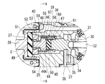
図1及び図3に示すように、本実施形態に係る気圧式倍力装置16は、タンデム型気圧式倍力装置であって、シェル17(ハウジング)の内部が隔壁18によって前室19と後室20との2室に区画されている。前室19及び後室20は、それぞれパワーピストン21、22によって定圧室19A、20Aと変圧室19B、20Bとに画成されている。定圧室19A、20A間及び変圧室19B、20B間は、それぞれ通路23、24によって連通されている。パワーピストン21、22には、略円筒状のバルブボディ25が連結されて、バルブボディ25は、シェル17の隔壁18及び後壁26に摺動可能かつ気密的に挿通されており、その後端部が後壁26から外部へ延出されている。バルブボディ25の前部には、リアクションディスク27(リアクション部材)を介して出力ロッド28が連結されており、出力ロッド28の先端部は、シェル17の前壁に取付けられるマスタシリンダ(図示せず)のピストンに連結される。
Hereinafter, an embodiment of the present invention will be described in detail with reference to the drawings.
As shown in FIGS. 1 and 3, a
バルブボディ25内には、ブレーキアシスト機構29、プランジャ30、ポペットシール31(弁手段)及び入力ロッド32が設けられている。プランジャ30の一端部とリアクションディスク27との間にブレーキアシスト機構29が介装され、プランジャ30の他端部に入力ロッド32の一端部が連結されている。入力ロッド32の他端部は、バルブボディ25の後端部に装着された通気性のダストシール33に挿通されて外部へ延出されており、その先端部にブレーキペダル(図示せず)が連結される。ポペットシール31は、バルブボディ25のシート部34及びプランジャ30のシート部35に着座しており、プランジャ30の移動によって、定圧室19A、20Aに連通する通路36と変圧室19B、20Bに連通する通路37との間及び通路35と大気との間を開閉する。
A
バルブボディ25の通路37には、ストップキー38が挿入されており、ストップキー38がシェル17のストッパ39に係合して、バルブボディ25の後退位置及びプランジャ30とバルブボディ25との相対位置を規定している。なお、図1及び図3において、符号40はエンジンの吸気管等の負圧源に接続されて定圧室19Aに負圧を導入する負圧導入口、41は入力ロッド32の戻しばね、42はポペットシール31を付勢する弁ばね、43はバルブボディ25の戻しばねを示す。
A
次に、本実施形態の要部であるブレーキアシスト機構29について図1を参照して説明する。
ブレーキアシスト機構29は、リアクションディスク27に当接するピストン44と、プランジャ30に当接する弾性部材45と、これらの外周に取付けられた段付スリーブ46と、スプリング47と、スプリングホルダ48とを備えている。
Next, the
The
ピストン44は、一端側にリアクションディスク27に当接する小径部49が突出され、他端側に弾性部材45と同径となるように縮径された当接部50が突出された段付の円柱状に形成されている。小径部49には、円筒状のレシオリング51が摺動可能に外嵌されている。レシオリング51は、バルブボディ25の前端部に取付けられた環状の受圧部材52に摺動可能に挿通されている。そして、レシリング51の外周に形成された段部53が受圧部材52の内周に形成された段部54に当接することによって、レシオリング51の後退位置が規定されている。図1に示す非制動位置において、ピストン44の小径部49及びレシオリング51の先端部とリアクションディスク27との間には、所定の隙間C(ジャンプインクリアランス)が設けられている。
The
弾性部材45は、プランジャ30とピストン44との間に介装されるゴム等の弾性体からなる円柱状の部材であり、プランジャ30の先端部とピストン44の当接部50と弾性部材45とが同径となっている。
The
段付スリーブ46は、ピストン44の外周に摺動可能に嵌合する大径円筒部55と、ピストン44の当接部50、弾性部材45及びプランジャ30の先端部の外周に摺動可能に嵌合する小径円筒部56とを有しており、図1及び図4に示すように、大径円筒部55と小径円筒部56との間に段部57が形成されている。大径円筒部55の側壁の端部には、図2及び図4に示すように、矩形の切欠部58が設けられており、切欠部58は、円周方向に沿って等間隔で3つ配置されている。
The stepped
スプリングホルダ48は、図1及び図5に示すように、ピストン44の小径部49が突出する端面の外周部に形成された環状の凹部44Aに嵌合するリング状の取付部59と、取付部59から径方向外側へ放射状に延び、折曲されて取付部59の軸方向に沿って延びる3つのアーム部60とを有している。アーム部60は、取付部59の周方向に沿って等間隔で3つ配置されており、段付スリーブ46の3つの切欠部58にそれぞれ挿入できるようになっている。また、アーム部60の先端部には、径方向内側に突出する爪部61が形成されている。
As shown in FIGS. 1 and 5, the
スプリング47は、ピストン44及び弾性部材45に嵌合された段付スリーブ46の段部57と、ピストン44の凹部44Aに取付部59が嵌合されたスプリングホルダ48の爪部61との間に介装されて、段付スリーブ46の段部57をピストン44の当接部50が突出された端面に常時押圧している。この状態で、段付スリーブ46の大径円筒部55の先端部がピストン44の小径部49が突出された端面から突出している。
The
以上のように構成した本実施形態の作用について次に説明する。
図1に示す非制動状態においては、ポペットシール31がシート部34、35に着座して、変圧室19B、20Bが大気及び定圧室19A、20A(負圧)から遮断されて、定圧室19A、20Aと変圧室19B、20Bと圧力が釣合っており、パワーピストン21、22に推力が発生しない。
Next, the operation of the present embodiment configured as described above will be described.
In the non-braking state shown in FIG. 1, the
ブレーキペダルの踏込み速度が低い通常のブレーキ操作においては、入力ロッド32によってプランジャ30を前進させると、シート部35がポペットシール31から離間して、変圧室19B、20Bに大気が導入されて、定圧室19A、20A(負圧)との間に圧力差が生じる。この圧力差によってパワーピストン21、22に推力(サーボ力)が発生して、バルブボディ25が前進してリアクションディスク27を介して出力ロッド28を押圧する。バルブボディ25の前進によってポペットシール31がシート部35に着座すると、大気の導入が停止して、定圧室19A、20Aと変圧室19B、20Bとの圧力差が維持される。このとき、出力ロッド28からリアクションディスク27に作用する反力の一部がブレーキアシスト機構29を介してプランジャ30及び入力ロッド32にフィードバックされる。
In a normal brake operation in which the depression speed of the brake pedal is low, when the
このとき、ブレーキアシスト機構29では、リアクションディスク27からの反力によって弾性部材45に軸方向の圧縮力が作用する。弾性部材45は、ピストン44の当接部50、プランジャ30の先端部及び段付スリーブ46の小径円筒部56によって囲まれた密閉空間内にあるため、軸方向の圧縮は、その体積弾性に依存し、弾性係数が充分大きくなるので、殆ど圧縮されない。したがって、ブレーキアシスト機構29は、軸方向に殆ど短縮されないので、リアクションディスク27からの反力は、そのままプランジャ30側に伝達されることになる。
At this time, in the brake assist
この場合、制動初期段階においては、ピストン44の小径部49とリアクションディスク27との隙間Cによって、プランジャ30は、リアクションディスク27からの反力を受けることなく前進することができるので、制動力を迅速に立ち上げることができる(ジャンプイン作用)。その後、リアクションディスク27からの反力がレシオリング51及びピストン44の小径部49を介してプランジャ30及び入力ロッド32にフィードバックされることにより、ブレーキペダル踏力に応じた制動力を発生させることができる。そして、レシオリング51の段部53が受圧部材52の段部54に当接した後は、リアクションディスク27からの反力に対する受圧面積が減少して倍力比が増大する。
In this case, in the initial stage of braking, the
入力ロッド32への入力を解除すると、戻しばね41のばね力によって、入力ロッド32及びプランジャ30が後退して、プランジャ30のシート部35がポペットシール31を押圧してバルブボディ25のシート部34から離間させる。これにより、定圧室19A、20Aと変圧室19B、20Bとが連通されて、これらの間の圧力差が解消され、パワーピストン21、22の推力が消失して、戻しばねに43によってバルブボディ25が後退して制動が解除される。
When the input to the
急制動時、すなわち、ブレーキペダルの踏込み速度が大きい場合、プランジャ30の移動に対して、パワーピストン21、22の推力によるバルブボディ25の追従動作に遅れが生じる。これにより、段付スリーブ46の大径円筒部55の先端部が受圧部材52に当接して、段付スリーブ46がピストン44に対して後退し、大径円筒部55が弾性部材45に重なる位置へ移動する。この状態では、図6に示すように、軸方向に圧縮された弾性部材45は、拡径方向への変形が許容されて、大径円筒部55によって形成される空間に押込まれるので、軸方向の圧縮に対する弾性係数が充分小さくなる。これにより、ブレーキアシスト機構29は、プランジャ30への入力及びリアクションディスク27からの反力によって軸方向に圧縮されることになる。その結果、リアクションディスク27からの反力を増大させることなく、プランジャ30を前進させて、シート部35をポペットシール31から離間させることができ、大気を変圧室19B、20Bに導入して大きなサーボ力を発生させることができる。このようにして、緊急時にブレーキアシスト機構29が作動して、弾性部材45の軸方向の圧縮を許容することにより、ブレーキペダルの操作力を軽減して迅速に大きな制動力を立ち上げることができる。
During sudden braking, that is, when the depression speed of the brake pedal is large, the follow-up operation of the
ブレーキアシスト機構29は、段付スリーブ46の大径円筒部にピストン44を嵌合し、小径円筒部56に弾性部材45を嵌合し、スプリングホルダ48をアーム部60を拡開させながら段付スリーブ46に外嵌して取付部59をピストン44の凹部44Aに嵌合し、更に、アーム部60を拡開させながらスプリング47を段付スリーブ46の段部57とスプリングホルダ48の爪部61との間に介装することにより、容易にサブアセンブリすることができる。これにより、従来のピストンとホルダとを連結するステムが不要となり、部品点数を削減すると共に組付性を向上させることができる。また、各部材の構造が簡単であり、製造コストの安価ですむ。
The
なお、上記実施形態では、段付スリーブ46の切欠部58及びスプリングホルダ48のアーム部60は、3つずつ設けられているが、これらの数は、2つ以上であればよく、適宜選択することができる。
In the above embodiment, three
16 気圧式倍力装置、17 シェル(ハウジング)、19A、20A 定圧室、19B、20B 変圧室、21、22 パワーピストン、25 バルブボディ、27 リアクションディスク(リアクション部材)、28 出力ロッド、29 ブレーキアシスト機構、30 プランジャ、31 ポペットシール(弁手段)、32 入力ロッド、44 ピストン、45 弾性部材、46 段付スリーブ、47 スプリング、48 スプリングホルダ、55 大径円筒部、56 小径円筒部、57 段部、59 取付部、60 アーム部、61 爪部
16 atmospheric pressure booster, 17 shell (housing), 19A, 20A constant pressure chamber, 19B, 20B variable pressure chamber, 21, 22 power piston, 25 valve body, 27 reaction disc (reaction member), 28 output rod, 29 brake assist Mechanism, 30 Plunger, 31 Poppet seal (valve means), 32 Input rod, 44 Piston, 45 Elastic member, 46 Stepped sleeve, 47 Spring, 48 Spring holder, 55 Large diameter cylindrical part, 56 Small diameter cylindrical part, 57 Step part , 59 Mounting part, 60 Arm part, 61 Claw part
Claims (1)
前記リアクション部材に対向するピストンと、該ピストンと前記プランジャとの間に介装された弾性部材と、前記ピストン、前記弾性部材及び前記プランジャの外周に摺動可能に嵌合して前記弾性部材の拡径を制限する小径円筒部と前記弾性部材の拡径を許容する大径円筒部とを有する段付スリーブと、前記ピストンの前記リアクション部材側の端面に係合する取付部と該取付部から前記段付スリーブの外周側を通って前記プランジャ側へ延びる複数のアーム部と該アーム部の先端部から径方向内側へ突出された爪部とを有するスプリングホルダと、前記段付スリーブの段部と前記爪部との間に介装されて前記段付スリーブを前記リアクション部材側へ付勢するスプリングとを備え、前記段付スリーブは、通常、前記スプリングの付勢力によって前記小径円筒部が前記弾性部材の拡径を制限する位置にあり、前記プランジャの前記バルブボディに対する速度又は移動量が所定値に達したとき、前記スプリングの付勢力に抗して移動して前記大径円筒部が前記弾性部材の拡径を許容するブレーキアシスト機構が設けられていることを特徴とする気圧式倍力装置。 The inside of the housing is defined as a constant pressure chamber and a variable pressure chamber by a power piston, and a plunger disposed in a valve body connected to the power piston is moved by an input rod, thereby opening valve means and operating gas in the variable pressure chamber. And a pressure difference is generated between the constant pressure chamber and the variable pressure chamber, and a thrust generated in the power piston due to the pressure difference is applied to the output rod via a reaction member, and the reaction from the output rod is performed. In a pneumatic booster configured to transmit a part of the reaction force acting on the member to the input rod,
A piston opposed to the reaction member; an elastic member interposed between the piston and the plunger; and a slidably fitted to the outer periphery of the piston, the elastic member, and the plunger, and A stepped sleeve having a small-diameter cylindrical portion that restricts expansion and a large-diameter cylindrical portion that allows expansion of the elastic member, an attachment portion that engages with the end surface of the piston on the reaction member side, and the attachment portion A spring holder having a plurality of arm portions extending to the plunger side through the outer peripheral side of the stepped sleeve, and a claw portion projecting radially inward from a distal end portion of the arm portion; and a step portion of the stepped sleeve and a spring for biasing the stepped sleeve is interposed between the claw portion to said reaction member, the stepped sleeve, usually, the biasing force of the spring The small-diameter cylindrical portion is in a position that limits the expansion of the elastic member, and when the speed or movement amount of the plunger with respect to the valve body reaches a predetermined value, it moves against the biasing force of the spring. A pneumatic booster characterized in that a brake assist mechanism is provided in which the large-diameter cylindrical portion allows the elastic member to expand in diameter.
Priority Applications (1)
| Application Number | Priority Date | Filing Date | Title |
|---|---|---|---|
| JP2005287642A JP4716100B2 (en) | 2005-09-30 | 2005-09-30 | Pneumatic booster |
Applications Claiming Priority (1)
| Application Number | Priority Date | Filing Date | Title |
|---|---|---|---|
| JP2005287642A JP4716100B2 (en) | 2005-09-30 | 2005-09-30 | Pneumatic booster |
Publications (2)
| Publication Number | Publication Date |
|---|---|
| JP2007098970A JP2007098970A (en) | 2007-04-19 |
| JP4716100B2 true JP4716100B2 (en) | 2011-07-06 |
Family
ID=38026357
Family Applications (1)
| Application Number | Title | Priority Date | Filing Date |
|---|---|---|---|
| JP2005287642A Expired - Fee Related JP4716100B2 (en) | 2005-09-30 | 2005-09-30 | Pneumatic booster |
Country Status (1)
| Country | Link |
|---|---|
| JP (1) | JP4716100B2 (en) |
Families Citing this family (2)
| Publication number | Priority date | Publication date | Assignee | Title |
|---|---|---|---|---|
| JP5333726B2 (en) * | 2008-10-31 | 2013-11-06 | 日立オートモティブシステムズ株式会社 | Pneumatic booster |
| JP6155502B2 (en) * | 2013-04-17 | 2017-07-05 | 日立オートモティブシステムズ株式会社 | Pneumatic booster |
Citations (2)
| Publication number | Priority date | Publication date | Assignee | Title |
|---|---|---|---|---|
| JPH0341421A (en) * | 1989-07-07 | 1991-02-21 | Sanyo Chem Ind Ltd | Electrolyte and electrochromic element |
| JP2004051078A (en) * | 2002-01-31 | 2004-02-19 | Tokico Ltd | Pneumatic booster |
Family Cites Families (2)
| Publication number | Priority date | Publication date | Assignee | Title |
|---|---|---|---|---|
| JPH0341421U (en) * | 1989-08-29 | 1991-04-19 | ||
| JP3041421U (en) * | 1997-03-12 | 1997-09-19 | 日本エービーエス株式会社 | Fluid pressure control valve |
-
2005
- 2005-09-30 JP JP2005287642A patent/JP4716100B2/en not_active Expired - Fee Related
Patent Citations (2)
| Publication number | Priority date | Publication date | Assignee | Title |
|---|---|---|---|---|
| JPH0341421A (en) * | 1989-07-07 | 1991-02-21 | Sanyo Chem Ind Ltd | Electrolyte and electrochromic element |
| JP2004051078A (en) * | 2002-01-31 | 2004-02-19 | Tokico Ltd | Pneumatic booster |
Also Published As
| Publication number | Publication date |
|---|---|
| JP2007098970A (en) | 2007-04-19 |
Similar Documents
| Publication | Publication Date | Title |
|---|---|---|
| US4173172A (en) | Tandem brake booster | |
| JP5321803B2 (en) | Pneumatic booster | |
| JP4716100B2 (en) | Pneumatic booster | |
| JP2004051078A (en) | Pneumatic booster | |
| JP4206877B2 (en) | Pneumatic booster | |
| US7472968B2 (en) | Vacuum type brake booster | |
| GB2032552A (en) | Vacuum brake boosters | |
| JP6155502B2 (en) | Pneumatic booster | |
| US7063002B2 (en) | Negative pressure type booster | |
| JP2020011609A (en) | Pneumatic booster | |
| JPH10230840A (en) | Penumatic booster | |
| JP5078796B2 (en) | Negative pressure booster | |
| JP4626773B2 (en) | Pneumatic booster | |
| WO2016203892A1 (en) | Booster device | |
| JP6179425B2 (en) | Pneumatic booster | |
| JP4626772B2 (en) | Pneumatic booster | |
| JP4583932B2 (en) | Pneumatic servo motor for auxiliary brake, manufacturing method and manufacturing apparatus thereof | |
| JP4419751B2 (en) | Negative pressure booster | |
| JP6297318B2 (en) | Pneumatic booster | |
| JP6260769B2 (en) | Negative pressure booster | |
| JP2019006300A (en) | Air pressure type booster | |
| KR100916397B1 (en) | Brake booster for vehicle | |
| JP2004058861A (en) | Pneumatic booster | |
| KR100673056B1 (en) | Brake booster for automobile | |
| JP3885178B2 (en) | Pneumatic booster |
Legal Events
| Date | Code | Title | Description |
|---|---|---|---|
| A621 | Written request for application examination |
Free format text: JAPANESE INTERMEDIATE CODE: A621 Effective date: 20080627 |
|
| A521 | Request for written amendment filed |
Free format text: JAPANESE INTERMEDIATE CODE: A821 Effective date: 20080630 |
|
| A711 | Notification of change in applicant |
Free format text: JAPANESE INTERMEDIATE CODE: A712 Effective date: 20090902 |
|
| RD03 | Notification of appointment of power of attorney |
Free format text: JAPANESE INTERMEDIATE CODE: A7423 Effective date: 20090902 |
|
| A521 | Request for written amendment filed |
Free format text: JAPANESE INTERMEDIATE CODE: A523 Effective date: 20090904 |
|
| A977 | Report on retrieval |
Free format text: JAPANESE INTERMEDIATE CODE: A971007 Effective date: 20100218 |
|
| A131 | Notification of reasons for refusal |
Free format text: JAPANESE INTERMEDIATE CODE: A131 Effective date: 20100929 |
|
| A521 | Request for written amendment filed |
Free format text: JAPANESE INTERMEDIATE CODE: A523 Effective date: 20101126 |
|
| TRDD | Decision of grant or rejection written | ||
| A01 | Written decision to grant a patent or to grant a registration (utility model) |
Free format text: JAPANESE INTERMEDIATE CODE: A01 Effective date: 20110309 |
|
| A01 | Written decision to grant a patent or to grant a registration (utility model) |
Free format text: JAPANESE INTERMEDIATE CODE: A01 |
|
| A61 | First payment of annual fees (during grant procedure) |
Free format text: JAPANESE INTERMEDIATE CODE: A61 Effective date: 20110316 |
|
| R150 | Certificate of patent or registration of utility model |
Free format text: JAPANESE INTERMEDIATE CODE: R150 Ref document number: 4716100 Country of ref document: JP Free format text: JAPANESE INTERMEDIATE CODE: R150 |
|
| FPAY | Renewal fee payment (event date is renewal date of database) |
Free format text: PAYMENT UNTIL: 20140408 Year of fee payment: 3 |
|
| R250 | Receipt of annual fees |
Free format text: JAPANESE INTERMEDIATE CODE: R250 |
|
| LAPS | Cancellation because of no payment of annual fees |