JP4715751B2 - Automatic peritoneal perfusion device and its drainage control method - Google Patents
Automatic peritoneal perfusion device and its drainage control method Download PDFInfo
- Publication number
- JP4715751B2 JP4715751B2 JP2006545180A JP2006545180A JP4715751B2 JP 4715751 B2 JP4715751 B2 JP 4715751B2 JP 2006545180 A JP2006545180 A JP 2006545180A JP 2006545180 A JP2006545180 A JP 2006545180A JP 4715751 B2 JP4715751 B2 JP 4715751B2
- Authority
- JP
- Japan
- Prior art keywords
- infusion
- pressure
- drainage
- mode
- reference value
- Prior art date
- Legal status (The legal status is an assumption and is not a legal conclusion. Google has not performed a legal analysis and makes no representation as to the accuracy of the status listed.)
- Expired - Fee Related
Links
Images


Classifications
-
- A—HUMAN NECESSITIES
- A61—MEDICAL OR VETERINARY SCIENCE; HYGIENE
- A61M—DEVICES FOR INTRODUCING MEDIA INTO, OR ONTO, THE BODY; DEVICES FOR TRANSDUCING BODY MEDIA OR FOR TAKING MEDIA FROM THE BODY; DEVICES FOR PRODUCING OR ENDING SLEEP OR STUPOR
- A61M1/00—Suction or pumping devices for medical purposes; Devices for carrying-off, for treatment of, or for carrying-over, body-liquids; Drainage systems
- A61M1/14—Dialysis systems; Artificial kidneys; Blood oxygenators ; Reciprocating systems for treatment of body fluids, e.g. single needle systems for hemofiltration or pheresis
- A61M1/28—Peritoneal dialysis ; Other peritoneal treatment, e.g. oxygenation
-
- A—HUMAN NECESSITIES
- A61—MEDICAL OR VETERINARY SCIENCE; HYGIENE
- A61M—DEVICES FOR INTRODUCING MEDIA INTO, OR ONTO, THE BODY; DEVICES FOR TRANSDUCING BODY MEDIA OR FOR TAKING MEDIA FROM THE BODY; DEVICES FOR PRODUCING OR ENDING SLEEP OR STUPOR
- A61M1/00—Suction or pumping devices for medical purposes; Devices for carrying-off, for treatment of, or for carrying-over, body-liquids; Drainage systems
- A61M1/14—Dialysis systems; Artificial kidneys; Blood oxygenators ; Reciprocating systems for treatment of body fluids, e.g. single needle systems for hemofiltration or pheresis
- A61M1/15—Dialysis systems; Artificial kidneys; Blood oxygenators ; Reciprocating systems for treatment of body fluids, e.g. single needle systems for hemofiltration or pheresis with a cassette forming partially or totally the flow circuit for the treating fluid, e.g. the dialysate fluid circuit or the treating gas circuit
- A61M1/152—Details related to the interface between cassette and machine
- A61M1/1522—Details related to the interface between cassette and machine the interface being evacuated interfaces to enhance contact
-
- A—HUMAN NECESSITIES
- A61—MEDICAL OR VETERINARY SCIENCE; HYGIENE
- A61M—DEVICES FOR INTRODUCING MEDIA INTO, OR ONTO, THE BODY; DEVICES FOR TRANSDUCING BODY MEDIA OR FOR TAKING MEDIA FROM THE BODY; DEVICES FOR PRODUCING OR ENDING SLEEP OR STUPOR
- A61M1/00—Suction or pumping devices for medical purposes; Devices for carrying-off, for treatment of, or for carrying-over, body-liquids; Drainage systems
- A61M1/14—Dialysis systems; Artificial kidneys; Blood oxygenators ; Reciprocating systems for treatment of body fluids, e.g. single needle systems for hemofiltration or pheresis
- A61M1/15—Dialysis systems; Artificial kidneys; Blood oxygenators ; Reciprocating systems for treatment of body fluids, e.g. single needle systems for hemofiltration or pheresis with a cassette forming partially or totally the flow circuit for the treating fluid, e.g. the dialysate fluid circuit or the treating gas circuit
- A61M1/156—Constructional details of the cassette, e.g. specific details on material or shape
- A61M1/1561—Constructional details of the cassette, e.g. specific details on material or shape at least one cassette surface or portion thereof being flexible, e.g. the cassette having a rigid base portion with preformed channels and being covered with a foil
-
- A—HUMAN NECESSITIES
- A61—MEDICAL OR VETERINARY SCIENCE; HYGIENE
- A61M—DEVICES FOR INTRODUCING MEDIA INTO, OR ONTO, THE BODY; DEVICES FOR TRANSDUCING BODY MEDIA OR FOR TAKING MEDIA FROM THE BODY; DEVICES FOR PRODUCING OR ENDING SLEEP OR STUPOR
- A61M1/00—Suction or pumping devices for medical purposes; Devices for carrying-off, for treatment of, or for carrying-over, body-liquids; Drainage systems
- A61M1/14—Dialysis systems; Artificial kidneys; Blood oxygenators ; Reciprocating systems for treatment of body fluids, e.g. single needle systems for hemofiltration or pheresis
- A61M1/15—Dialysis systems; Artificial kidneys; Blood oxygenators ; Reciprocating systems for treatment of body fluids, e.g. single needle systems for hemofiltration or pheresis with a cassette forming partially or totally the flow circuit for the treating fluid, e.g. the dialysate fluid circuit or the treating gas circuit
- A61M1/159—Dialysis systems; Artificial kidneys; Blood oxygenators ; Reciprocating systems for treatment of body fluids, e.g. single needle systems for hemofiltration or pheresis with a cassette forming partially or totally the flow circuit for the treating fluid, e.g. the dialysate fluid circuit or the treating gas circuit specially adapted for peritoneal dialysis
-
- A—HUMAN NECESSITIES
- A61—MEDICAL OR VETERINARY SCIENCE; HYGIENE
- A61M—DEVICES FOR INTRODUCING MEDIA INTO, OR ONTO, THE BODY; DEVICES FOR TRANSDUCING BODY MEDIA OR FOR TAKING MEDIA FROM THE BODY; DEVICES FOR PRODUCING OR ENDING SLEEP OR STUPOR
- A61M1/00—Suction or pumping devices for medical purposes; Devices for carrying-off, for treatment of, or for carrying-over, body-liquids; Drainage systems
- A61M1/14—Dialysis systems; Artificial kidneys; Blood oxygenators ; Reciprocating systems for treatment of body fluids, e.g. single needle systems for hemofiltration or pheresis
- A61M1/28—Peritoneal dialysis ; Other peritoneal treatment, e.g. oxygenation
- A61M1/282—Operational modes
-
- A—HUMAN NECESSITIES
- A61—MEDICAL OR VETERINARY SCIENCE; HYGIENE
- A61M—DEVICES FOR INTRODUCING MEDIA INTO, OR ONTO, THE BODY; DEVICES FOR TRANSDUCING BODY MEDIA OR FOR TAKING MEDIA FROM THE BODY; DEVICES FOR PRODUCING OR ENDING SLEEP OR STUPOR
- A61M1/00—Suction or pumping devices for medical purposes; Devices for carrying-off, for treatment of, or for carrying-over, body-liquids; Drainage systems
- A61M1/36—Other treatment of blood in a by-pass of the natural circulatory system, e.g. temperature adaptation, irradiation ; Extra-corporeal blood circuits
- A61M1/3621—Extra-corporeal blood circuits
- A61M1/3653—Interfaces between patient blood circulation and extra-corporal blood circuit
- A61M1/3656—Monitoring patency or flow at connection sites; Detecting disconnections
-
- A—HUMAN NECESSITIES
- A61—MEDICAL OR VETERINARY SCIENCE; HYGIENE
- A61M—DEVICES FOR INTRODUCING MEDIA INTO, OR ONTO, THE BODY; DEVICES FOR TRANSDUCING BODY MEDIA OR FOR TAKING MEDIA FROM THE BODY; DEVICES FOR PRODUCING OR ENDING SLEEP OR STUPOR
- A61M1/00—Suction or pumping devices for medical purposes; Devices for carrying-off, for treatment of, or for carrying-over, body-liquids; Drainage systems
- A61M1/14—Dialysis systems; Artificial kidneys; Blood oxygenators ; Reciprocating systems for treatment of body fluids, e.g. single needle systems for hemofiltration or pheresis
- A61M1/15—Dialysis systems; Artificial kidneys; Blood oxygenators ; Reciprocating systems for treatment of body fluids, e.g. single needle systems for hemofiltration or pheresis with a cassette forming partially or totally the flow circuit for the treating fluid, e.g. the dialysate fluid circuit or the treating gas circuit
- A61M1/152—Details related to the interface between cassette and machine
- A61M1/1524—Details related to the interface between cassette and machine the interface providing means for actuating on functional elements of the cassette, e.g. plungers
-
- A—HUMAN NECESSITIES
- A61—MEDICAL OR VETERINARY SCIENCE; HYGIENE
- A61M—DEVICES FOR INTRODUCING MEDIA INTO, OR ONTO, THE BODY; DEVICES FOR TRANSDUCING BODY MEDIA OR FOR TAKING MEDIA FROM THE BODY; DEVICES FOR PRODUCING OR ENDING SLEEP OR STUPOR
- A61M1/00—Suction or pumping devices for medical purposes; Devices for carrying-off, for treatment of, or for carrying-over, body-liquids; Drainage systems
- A61M1/14—Dialysis systems; Artificial kidneys; Blood oxygenators ; Reciprocating systems for treatment of body fluids, e.g. single needle systems for hemofiltration or pheresis
- A61M1/15—Dialysis systems; Artificial kidneys; Blood oxygenators ; Reciprocating systems for treatment of body fluids, e.g. single needle systems for hemofiltration or pheresis with a cassette forming partially or totally the flow circuit for the treating fluid, e.g. the dialysate fluid circuit or the treating gas circuit
- A61M1/154—Dialysis systems; Artificial kidneys; Blood oxygenators ; Reciprocating systems for treatment of body fluids, e.g. single needle systems for hemofiltration or pheresis with a cassette forming partially or totally the flow circuit for the treating fluid, e.g. the dialysate fluid circuit or the treating gas circuit with sensing means or components thereof
-
- A—HUMAN NECESSITIES
- A61—MEDICAL OR VETERINARY SCIENCE; HYGIENE
- A61M—DEVICES FOR INTRODUCING MEDIA INTO, OR ONTO, THE BODY; DEVICES FOR TRANSDUCING BODY MEDIA OR FOR TAKING MEDIA FROM THE BODY; DEVICES FOR PRODUCING OR ENDING SLEEP OR STUPOR
- A61M1/00—Suction or pumping devices for medical purposes; Devices for carrying-off, for treatment of, or for carrying-over, body-liquids; Drainage systems
- A61M1/14—Dialysis systems; Artificial kidneys; Blood oxygenators ; Reciprocating systems for treatment of body fluids, e.g. single needle systems for hemofiltration or pheresis
- A61M1/15—Dialysis systems; Artificial kidneys; Blood oxygenators ; Reciprocating systems for treatment of body fluids, e.g. single needle systems for hemofiltration or pheresis with a cassette forming partially or totally the flow circuit for the treating fluid, e.g. the dialysate fluid circuit or the treating gas circuit
- A61M1/155—Dialysis systems; Artificial kidneys; Blood oxygenators ; Reciprocating systems for treatment of body fluids, e.g. single needle systems for hemofiltration or pheresis with a cassette forming partially or totally the flow circuit for the treating fluid, e.g. the dialysate fluid circuit or the treating gas circuit with treatment-fluid pumping means or components thereof
-
- A—HUMAN NECESSITIES
- A61—MEDICAL OR VETERINARY SCIENCE; HYGIENE
- A61M—DEVICES FOR INTRODUCING MEDIA INTO, OR ONTO, THE BODY; DEVICES FOR TRANSDUCING BODY MEDIA OR FOR TAKING MEDIA FROM THE BODY; DEVICES FOR PRODUCING OR ENDING SLEEP OR STUPOR
- A61M2205/00—General characteristics of the apparatus
- A61M2205/12—General characteristics of the apparatus with interchangeable cassettes forming partially or totally the fluid circuit
Landscapes
- Health & Medical Sciences (AREA)
- Heart & Thoracic Surgery (AREA)
- Urology & Nephrology (AREA)
- Emergency Medicine (AREA)
- Vascular Medicine (AREA)
- Hematology (AREA)
- Anesthesiology (AREA)
- Biomedical Technology (AREA)
- Engineering & Computer Science (AREA)
- Life Sciences & Earth Sciences (AREA)
- Animal Behavior & Ethology (AREA)
- General Health & Medical Sciences (AREA)
- Public Health (AREA)
- Veterinary Medicine (AREA)
- Cardiology (AREA)
- External Artificial Organs (AREA)
Description
本発明は自動腹膜灌流装置に関し、特にその排液制御の改良技術に関する。 The present invention relates to an automatic peritoneal perfusion device, and more particularly to an improved technique for controlling the drainage thereof.
現在、日本国内で20万人ほどの慢性腎不全患者がいるといわれており、その92−93%の患者が血液透析、残りの7−8%の患者が腹膜透析による維持療法をそれぞれ受けている。
腹膜透析では、患者は主に在宅で透析を行うことができる。これは患者自らが透析液をカテーテルを用いて腹腔内に入れ、数時間貯留したのち、排液するステップを一日数回繰り返す。患者は毎回の排液時における体内からの過剰水分排出量(除水量という)を記録しておき、以後の診察時に医者に提示し、処方を仰ぐようにする。このような腹膜透析の方法をCAPD(Continuous Ambulatory Pelitoneal Dialysis;連続携行式腹膜透析)と呼ぶ。腹膜透析療法は、血液透析療法に比べて治療費が安く、通院等の負担も小さいため、日本国内でも自宅療法が広がりつつある。Currently, it is said that there are about 200,000 chronic renal failure patients in Japan, of which 92-93% receive hemodialysis and the remaining 7-8% receive peritoneal dialysis maintenance therapy. Yes.
In peritoneal dialysis, patients can mainly perform dialysis at home. The patient himself or herself puts the dialysate into the abdominal cavity using a catheter, stores it for several hours, and then repeats the draining step several times a day. The patient records the amount of excess water excreted from the body at each drainage (referred to as the amount of water removed) and presents it to the doctor during subsequent examinations for a prescription. Such a method of peritoneal dialysis is referred to as CAPD (Continuous Ambientity Peltonial Dialysis). Peritoneal dialysis therapy is cheaper than hemodialysis therapy, and the burden of visiting hospitals is small, so home therapy is spreading in Japan.
この腹膜透析療法において近年では、例えば特許文献1、2に記載されているように、一定の透析操作を自動的に行うための自動腹膜透析装置(APD;Automaticaly Pelitoneal Dialysis、自動腹膜灌流装置とも称される。以下「APD」と略す。)が知られている。
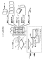
このAPDは、例えば図1のAPD2に示す構成を持つものであって、筐体203に表示部202、操作部201、ヒータ部21、ドア204、チャンバー部205を備える。また筐体203の内部には、透析液、排液等を輸液するためのエアシリンダ等が配設されている。当該APD2には、患者の測定データを出力するためのプリンタも接続される。In recent years, in this peritoneal dialysis therapy, as described in, for example,
This APD has, for example, the configuration shown in
エアシリンダは、直動アクチュエータ等のシリンダからなる公知のエア輸液ポンプであって、制御部からの指示に基づき、プランジャ軸のストロークに応じて正確な分量及び速度で輸液を行う。また、エアシリンダの代わりにロータリーポンプを用いることができるが、安定した制御を行うためにはエアシリンダが望ましい。
ヒータ部21は、透析液を患者に対して輸液する際、予め所定温度に暖める役目をなす。The air cylinder is a known air infusion pump composed of a cylinder such as a linear actuator, and infuses at an accurate amount and speed according to the stroke of the plunger shaft based on an instruction from the control unit. A rotary pump can be used in place of the air cylinder, but an air cylinder is desirable for stable control.
The
制御部は、ユーザから入力部より入力される各種条件に基づき、エアシリンダ等の駆動を行う。また、設定条件や腹膜透析により得られた患者データを表示する役目も持つ。
チャンバー部205は、エアシリンダの駆動力を輸液ライン側に伝達するための部分であって、当該チャンバー部に対して使い捨ての輸液ラインユニットとしてディスポ回路1が装着される。当該ディスポ回路1はユーザによる操作の容易可、汚染等の問題発生を抑制するためのものであり、その全体構成は図3に示すように、円形のカセット部11に対してマニホールド(多分岐導管)10が接続され、さらに導管として各種ライン10a〜10fが接続されてなる。各種ライン10a〜10eには、それぞれのラインに応じて、透析液バッグ、排液バッグ、濃度変更液バッグ、加温バッグ、患者へのカテーテル等が接続される。The control unit drives the air cylinder or the like based on various conditions input from the input unit by the user. It also has the role of displaying the set conditions and patient data obtained by peritoneal dialysis.
The
このうちカセット部11は図3のように、一定容積を持つ椀状の上蓋11aおよび下蓋11bの間に、天然ゴムや剛性エラストマーで形成された可撓性隔膜(ダイアフラム)11cが内部空間を区画するように張架され、上蓋11a中央に液体開口部11eが形成され、下蓋11b中央に気体開口部11dが形成されたチャンバーとしての構成を持つ。当該カセット部11は、使用に際しては図4(a)から(c)に示すように、レバー2042を操作してドア204を開けたのち、係合部2051のパッキン2052及び気体開口部11d周辺に合わせてセットされ、ドア204を閉めることでドア204の裏面に配された凸部2041とパッキン2052の間において気密的に装着される。マニホールド10から延出される各種ライン10aから10eは、溝部2053から筐体外部に取り出される。これにより、駆動時にエアシリンダからの吸引力が気体開口部11dを通じてカセット部11内に作用すれば、ダイアフラム11cが下蓋11b内面に吸引され、また反対にエアシリンダから排出力が作用すれば上蓋11a内面に沿って変形する。この動作を繰り返すことで、液体開口部11eからカセット部11内に輸液が導入・排出されるので、当該カセット部11を中心にディスポ回路10全体にわたり、各種ライン10aから10eを通じて各種溶液が輸液される。ここで当該APD2では、輸液ポンプにエアシリンダを用いることにより、その精密作動によって正確な輸液設定が行えるようになっている。 Among these, as shown in FIG. 3, the
以上の構成を持つAPD2によれば、自宅等で患者自身でも簡便に腹膜透析を行えるので、広範囲な普及が期待されている。
ところで、上記構成例およびその他の一般的なAPDにおいて、患者の腹腔内における貯留液を排液処理する場合では、以下の課題が残されている。
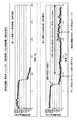
すなわち、APDを用いない腹膜透析方法では、患者は病院等の施設において、椅子等に座った体勢で、いわゆる自然落差方式により排液処理を行う。このとき患者の腹腔では、その下部に貯留液が重力により集中し、比較的腹腔内の空間が広くなる。したがって、腹腔の下部に挿入したカテーテルの先端付近の自由度は比較的高いので、液の流通がよく、短時間で排液がなされる(図5(a)のグラフを参照)。By the way, in the above configuration example and other general APDs, the following problems remain when the stored liquid in the abdominal cavity of the patient is drained.
That is, in a peritoneal dialysis method that does not use APD, a patient performs drainage treatment by a so-called natural drop method in a posture such as sitting in a chair or the like in a facility such as a hospital. At this time, in the abdominal cavity of the patient, the stored liquid concentrates in the lower part by gravity, and the space in the abdominal cavity becomes relatively wide. Therefore, since the degree of freedom near the tip of the catheter inserted in the lower part of the abdominal cavity is relatively high, the fluid can be circulated and drained in a short time (see the graph in FIG. 5A).
しかしながら、APDは患者が昼間の活動時間確保等の目的で、自宅において就寝中に透析処理を行うために用いられることが多いため、排液処理時には患者は布団の上に横臥した状態となる。このような体勢では、腹腔は身体に沿って比較的大きな面積にわたり広がるので、カテーテル先端が貯留液に対して十分に届かなくなる場合がある。
さらに、APDでは圧力方式に基づき駆動するため、エアシリンダの吸引力が強いと、カテーテル先端付近の腹腔が吸い寄せられ、フィブリンが変形したり、カテーテル先端周辺が閉塞状態になり、カテーテルに対し、部分的に貯留液が届かなくなることが考えられる。However, since APD is often used to perform dialysis treatment while sleeping at home for the purpose of ensuring daytime activity time, the patient is lying on the futon during drainage treatment. In such a posture, since the abdominal cavity extends over a relatively large area along the body, the catheter tip may not reach the stored fluid sufficiently.
Furthermore, since the APD is driven based on the pressure method, if the suction force of the air cylinder is strong, the abdominal cavity near the tip of the catheter is sucked, the fibrin is deformed, and the periphery of the tip of the catheter is blocked, It is conceivable that the stored liquid will not reach.
このような現象の発生により、腹腔内にまだ貯留液が残っているにもかかわらず、短期間の内には十分に排液処理がなされないという不具合がみられることがある(図5(b)を参照)。
本発明は以上の課題に鑑みて為されたものであって、その目的は、カテーテルの閉塞を防止し、且つ腹腔内での貯留液の残存を抑制して、比較的迅速に患者の排液処理を行うことが可能な自動腹膜灌流装置と、その排液制御方法を提供することにある。Due to the occurrence of such a phenomenon, there may be a problem that the drainage process is not sufficiently performed within a short period of time even though the stored liquid remains in the abdominal cavity (FIG. 5B). )).
The present invention has been made in view of the above problems, and its object is to prevent the catheter from being blocked and suppress the remaining of the stored liquid in the abdominal cavity, thereby draining the patient relatively quickly. It is an object of the present invention to provide an automatic peritoneal perfusion device capable of performing processing and a drainage control method thereof.
上記課題を解決するために、本発明は、患者の腹腔内における貯留液を身体外へ輸液する輸液ポンプと、当該輸液ポンプのドライバと、当該ドライバに接続された制御部とを備える自動腹膜灌流装置であって、前記制御部は、前記ドライバを介して輸液ポンプを駆動することで第一の排液速度で貯留液の排液処理を行う第一モードと、前記第一の排液速度よりも遅い第二の排液速度で排液処理を行う第二モードとからなる制御モードに基づき制御され、且つ、所定のタイミングで輸液ポンプの輸液圧を第一圧まで高めた後に、第一モードから第二モードへ切り替える制御モード切替手段を備える構成とすることもできる。 In order to solve the above problems, the present invention provides an automatic peritoneal perfusion comprising an infusion pump for transfusing a stored fluid in a patient's abdominal cavity to the outside of the body, a driver for the infusion pump, and a control unit connected to the driver. A first mode for draining a stored liquid at a first drainage speed by driving an infusion pump via the driver, and the first drainage speed. The first mode is controlled based on a control mode consisting of a second mode in which drainage treatment is performed at a slower second drainage speed and the infusion pressure of the infusion pump is increased to the first pressure at a predetermined timing. It can also be set as the structure provided with the control mode switching means which switches to 2nd mode.
ここで前記制御モード切替手段は、前記排液処理にかかる排液量、前記輸液ポンプにおける輸液圧、排液処理時間のいずれかが所定の判断値に達したことに基づき切替を行う構成とすることもできる。
さらに前記装置は、輸液ポンプの輸液圧を検出する圧力計測手段を備え、前記制御部は前記第一モードにおいて、排液処理にかかる輸液圧が第一基準値まで下降したことが前記圧力計測手段により検出されるまで排液処理を行い、前記検出後は、輸液圧を第一圧まで高め、一旦停止後、当該輸液圧が前記第一基準値よりも低い第二基準値に下降するまで排液処理を継続する構成とすることもできる。Here, the control mode switching means is configured to perform switching based on any of the drainage amount for the drainage treatment, the infusion pressure in the infusion pump, and the drainage treatment time reaching a predetermined judgment value. You can also.
Further, the apparatus includes pressure measuring means for detecting an infusion pressure of an infusion pump, and the control section determines that the infusion pressure for drainage processing has dropped to a first reference value in the first mode. After the detection, the infusion pressure is increased to the first pressure, and after the stop, the infusion pressure is temporarily reduced until the infusion pressure falls to a second reference value lower than the first reference value. It can also be set as the structure which continues a liquid process.
さらに第二モードには複数のサブモードが含まれており、各サブモードでは、前記制御部は輸液圧が第二基準値に達した後一旦停止し、その後は第二圧まで上昇させ、再度、第二基準値に下降されるまで排液処理を継続し、第二基準値到達後は、輸液圧を第二圧に高め、一旦停止後、第二基準値に下降するまで排液処理を継続する構成とすることもできる。 Further, the second mode includes a plurality of sub-modes. In each sub-mode, the control unit temporarily stops after the infusion pressure reaches the second reference value, and then increases to the second pressure. The drainage process is continued until the second reference value is lowered.After reaching the second reference value, the infusion pressure is increased to the second pressure, and after stopping, the drainage process is continued until the second reference value is lowered. It can also be configured to continue.
ここで第一圧としては、陽圧、第二圧としては、略大気圧と設定することができる。
また具体的に本発明は、前記輸液ポンプはエアシリンダであり、駆動時の当該エアシリンダの各ストロークに対応して輸液が一定量ごとに行われる構成であって、前記制御部は、圧力計測手段により前記第一基準値が検出された時点のストローク中における輸液量を測定し、当該測定した輸液量以下の量の輸液を腹腔内に戻すことで輸液圧が前記第一圧に調整される構成とすることができる。Here, the positive pressure can be set as the first pressure, and the atmospheric pressure can be set as the second pressure.
More specifically, the present invention is such that the infusion pump is an air cylinder, and infusion is performed for each fixed amount corresponding to each stroke of the air cylinder during driving, and the control unit is configured to measure pressure. The infusion pressure in the stroke at the time when the first reference value is detected by the means is measured, and the infusion pressure is adjusted to the first pressure by returning the infusion to the abdominal cavity in an amount equal to or less than the measured infusion volume. It can be configured.
さらに前記輸液ポンプは、輸液チューブおよびチャンバーが接続されてなる輸液回路が、前記チャンバーにおいて装着される構成であって、当該チャンバーは、中空の筐体に、気体が導入排出される気体開口部と、液体が吸入排出される液体開口部とが、可撓性隔膜を介して配された構成であり、輸液ポンプは前記チャンバーの気体開口部に対して装着され、駆動時に当該輸液ポンプの駆動力が気体開口部からチャンバー内に及ぶことで可撓性隔膜が変形し、液体開口部を通じて輸液がなされる構成とすることができる。 Further, the infusion pump is configured such that an infusion circuit in which an infusion tube and a chamber are connected is mounted in the chamber, and the chamber has a gas opening through which a gas is introduced into and discharged from a hollow housing. And a liquid opening through which liquid is sucked and discharged is arranged through a flexible diaphragm, and the infusion pump is attached to the gas opening of the chamber, and the driving force of the infusion pump during driving When the gas reaches from the gas opening into the chamber, the flexible diaphragm is deformed, and infusion can be performed through the liquid opening.
上記各構成を持つ本発明の自動腹膜灌流装置では、駆動時において輸液ポンプの輸液圧を測定し、当該輸液圧を所定値と参酌することにより、排液速度を段階的に変調する構成となっている。
このため、例えば第一モードの排液処理中において、ポンプの輸液圧が強すぎてカテーテル周辺の腹腔が吸い寄せられ、当該カテーテル先端付近が閉塞状態となっても、排液速度を落とし、又は輸液圧を一度戻すことで、前記カテーテルに対して吸い寄せられた腹腔の形状が復元され、当該閉塞を解消することが可能となる。その後は制御モード切替手段を用いて第二モードに切り替えることで排液を継続でき、トータルとして比較的短時間で排液の大部分を行うことが実現される。In the automatic peritoneal perfusion apparatus of the present invention having the above-described configurations, the infusion pressure of the infusion pump is measured at the time of driving, and the infusion pressure is taken into consideration with a predetermined value to modulate the drainage rate stepwise. ing.
For this reason, for example, during the drainage process in the first mode, even if the infusion pressure of the pump is too strong and the abdominal cavity around the catheter is sucked and the vicinity of the distal end of the catheter becomes blocked, the drainage rate is reduced, or the infusion By returning the pressure once, the shape of the abdominal cavity sucked against the catheter is restored, and the blockage can be resolved. Thereafter, by switching to the second mode using the control mode switching means, the drainage can be continued, and it is realized that the drainage is mostly performed in a relatively short time as a total.
その結果、患者の腹腔内に貯留液が残されたまま排液処理が終了してしまうことを防止し、良好な排液処理を行うことが可能となっている。
また、本発明における排液処理では、排液速度を場合に応じて適宜変調するので、当該排液処理が比較的迅速になされる。具体的には、第一モードにおいて、輸液圧が一定の陰圧に達するまでは、従来と同様もしくはそれ以上の比較的早い第一の排液速度にて排液を行うことが可能であり、一方閉塞を生じた場合でも緩やかな第二の排液速度で排液処理を継続でき、結果的に迅速な排液がなされる。As a result, it is possible to prevent the drainage process from being completed while the stored liquid remains in the abdominal cavity of the patient, and to perform a good drainage process.
Further, in the drainage process according to the present invention, the drainage rate is appropriately modulated depending on the case, so that the drainage process is performed relatively quickly. Specifically, in the first mode, until the infusion pressure reaches a certain negative pressure, it is possible to perform drainage at a relatively fast first drainage rate as in the prior art or higher, On the other hand, even when the blockage occurs, the drainage process can be continued at a gentle second drainage rate, and as a result, a rapid drainage is performed.
また、輸液圧が所定の判断値に達した後は、第一の排液速度よりも遅い速度で排液処理を継続されるが、再び上記と同様の理由によりカテーテルが閉塞状態となっても、輸液圧を戻すことで排液を継続できる可能性が高められる。このように本発明では、排液処理の全体にわたってカテーテルが閉塞状態となる時間を短縮することが図られ、従来の装置と遜色ない迅速な速度で排液処理を行えるという効果が奏される。 In addition, after the infusion pressure reaches a predetermined judgment value, the drainage process is continued at a speed slower than the first drainage speed. However, even if the catheter is blocked again for the same reason as described above. The possibility of being able to continue draining is increased by returning the infusion pressure. As described above, in the present invention, it is possible to shorten the time during which the catheter is closed during the entire drainage process, and the drainage process can be performed at a speed as high as that of the conventional apparatus.
なお、以下で言及する輸液圧とは、原則としてポンプの吸引圧を指し、断りのない限り、腹腔内での圧力を示すものではない。 The infusion pressure mentioned below indicates the pump suction pressure in principle, and does not indicate the pressure in the abdominal cavity unless otherwise noted.
1 ディスポ回路
2 自動腹膜灌流装置(APD)
10 マニホールド
10a〜10f、30a、30b ライン
11 カセット部
11a 上蓋
11b 下蓋
11c ダイアフラム
11d 開口部
20 CPU
22 主記憶部
23 クランプ制御部
24 エアバルブ
25 圧力センサ
26 フォトエンコーダ
27 制御部
28 エアシリンダ(輸液ポンプ)
201 表示部
202 入力部
204 ドア
205 チャンバー部
2051 係合部
k1〜k5 クランプ1
10
22
201
以下、本発明の実施の形態について説明する。
実施の形態1Embodiments of the present invention will be described below.
Embodiment 1
本実施の形態1におけるAPDは、全体的には前述した図1に記載のAPD2を利用した構成となっている。したがって、当該APD2の全体的な機能と、本実施の形態1の特徴部分について主に説明する。
<APD2の内部構成について>
本実施の形態1のAPD2は、その構成を機能ブロックとして表すと図2に示される。The APD according to the first embodiment has a configuration using the
<Internal configuration of APD2>
The
すなわち、具体的にはCPU20に対し、筐体外部に露出するように配されたヒータ部21、入力部202、表示部201のほか、図3に示すようにエアシリンダ28の駆動状態をCPU20にフィードバックする各種手段として、エアバルブ24、圧力センサ(圧力計測手段)25、フォトエンコーダ26等、またディスポ回路10の各種ライン10a〜10eを側面より押圧・解放して流通制御するクランプk1〜k5をそれぞれコントロールするクランプ制御部23が接続されている。 Specifically, in addition to the
クランプ制御部23は、CPU20の制御下において、APD2駆動時に適切なタイミングでクランプk1〜k5の開閉を制御することで、ディスポ回路11内の輸液方向を調節するものである。
例えば、クランプ制御部23は排液処理においては排液バッグが接続された排液ライン10a、マニホールド10、カセット部11、患者ライン10eのみに排液が流れるように、まずクランプk2からk4を閉じた状態とする。そして、患者から排液を行う際には、クランプk1を閉じ、クランプk5を開けた状態でエアシリンダ28を駆動する。一度のエアシリンダ駆動により、ダイアフラム11が半ストローク(上蓋11a側から下蓋11b側に)移動したのち、今度はクランプk5を閉じ、クランプk1を開けた状態でエアシリンダ28を駆動する。これによりダイアフラム11が残りの半ストローク(下蓋11b側から上蓋11a側に)で移動することによって、排液バッグ側に排液を輸液することができる。The
For example, in the drainage process, the
エアシリンダ28は、直接の駆動は制御部27が行い、当該制御部27に対してCPU20が接続されるようになっている。
ヒータ部21は、電熱体を内蔵してなるものであって、CPU20が所定の電力を供給することで、透析液を予め加温する役目をなす。
表示部201は、LCDユニットを利用してなり、CPU20は入力部202を介したユーザからの求めまたは駆動プログラムによる設定により、駆動時における各透析設定条件、治療開始/停止状態、治療結果等を適宜表示するものである。The
The
The
エアバルブ24は、例えば公知のダイアフラム式電磁バルブで構成されており、係合部2051に接続されたエアチューブ30aに分岐するエアチューブ30bに配設されている。CPU20は、同じくエアチューブ30a、30bに設けられた圧力センサ25の検出値に基づき、所定のタイミングで電力供給を行うことで、エアチューブ30a、30b内のエアーを外部に排出し、当該エアチューブ30a、30bの圧力調節をなすようになっている。 The
圧力センサ25としては、圧電素子、或いはピエゾ抵抗効果を利用した半導体圧力センサ等を用いることができる。CPU20は、エアチューブ30a、30bを流通するエア圧と、ディスポ回路10中を流通する輸液圧とが、互いに比例関係または略同一関係にあることから、当該圧力センサ25の検出値を元に輸液圧を換算できるようになっている。或いは、ディスポ回路10に対して接続される別個の圧力センサ(不図示)を設け、当該センサをCPUが管理するようにしてもよい。 As the
エアシリンダ28は、フォトエンコーダ26、制御部27との一体的な組み合わせで用いられるようになっている。
エアシリンダ28は、シリンダ筐体に対して直動軸であるプランジャが、電磁コイルとともに挿入された構成を持つ直動アクチュエータであり、エアチューブ30a、30bに接続されている。そして制御部27およびCPU20からの制御に伴う給電により、シリンダ筐体に対してプランジャが挿入(露出)することによりエアーが排出(吸入)され、これに伴って気圧が上昇(減圧)される。エアシリンダの構成としては、この他に送りネジと送りナットを利用し、モータの回転軸が送りネジに伝達されることで、送りナットに連結されたプランジャを挿入(露出)させるようにしてもよい。The
The
エアシリンダ28の容積は適宜選択できる(70〜100mLの範囲が望ましい)が、輸液量の測定容易可のためエアシリンダ28の駆動とカセット部11の輸液体積とをシンクロさせること、またプライミング処理時にはカセット部11の容積よりも大量の輸液を行う必要があることから、ここではカセット部11の輸液体積(50mL)よりも大容量の100mLとしている。APD2におけるエアシリンダ28の容積としては、カセット部11の容積の1.4〜2.0倍にすることが望ましい。 The volume of the
プランジャの移動量はフォトエンコーダ26によって検出され、CPU20により監視されているが、前記検出値は制御部27に監視させるようにしてもよい。
具体的には、透析液或いは腹腔からの排液量の測定については、CPU20がカセット部11の容積の整数倍に基づいて計量することで可能である。つまり、APD2ではカセット部11のダイアフラム11cの脈動により輸液がなされるので、例えばカセット部11の容積が50mLの場合、
チャンバー部容積(50mL)×プランジャのフルストローク往復運動回数=輸液総量
と換算することにより計量が可能である。なお、ここで言う「プランジャのフルストローク往復運動回数」は、シリンダ筐体に対するプランジャの相対的位置より、当然ながら自然数ではなく、端数となることもあり得る。Although the movement amount of the plunger is detected by the
Specifically, the measurement of the amount of dialysate or drainage from the abdominal cavity can be performed by the
It can be measured by converting the following: chamber volume (50 mL) × plunger full stroke reciprocating motion = total infusion volume. Note that the “number of full-stroke reciprocations of the plunger” referred to here may naturally be a fraction, not a natural number, based on the relative position of the plunger with respect to the cylinder housing.
また、エアシリンダ28及びカセット部11の各最大容積が既知であり、当該エアシリンダ28とカセット部11の駆動が互いにシンクロしていることから、現時点でカセット部11に存在する液量は、例えばその時点でのエアシリンダ28の容積(プランジャの押し込み量で変化する)をCPU20がフォトエンコーダ26で検出することによって把握することができる。 In addition, since the maximum volumes of the
なお、このようなAPDを利用した従来の一般的な測定方法については、例えば特開平10−211276号公報に詳しく開示されている。
26のエンコーダとしては、上記フォトエンコーダ(フォトインタラプタ)に限定せず、スライダ抵抗器等を用いてもよい。
CPU20は、APD2を全体的に制御する役目をなすものであって、ハードディスク等からなる主記憶部22が接続されている。そして、当該主記憶部22に格納されたプログラムを適宜読み込み、実行することで、所定の制御パターン(前記駆動プロセス)に基づいて前記各機能部21〜28を個別的に制御する。CPU20はこの制御パターンに基づき、後述の制御モードを切り替える手段としても動作する。A conventional general measurement method using such an APD is disclosed in detail in, for example, Japanese Patent Laid-Open No. 10-211276.
The
The
なお、CPU20,主記憶部22はAPD2に内蔵する構成の他、一般的なパーソナルコンピュータ(PC)を利用することも可能である。
以上の構成によれば、CPU20は制御部27を介してエアシリンダ28の駆動速度を変調することで、ディスポ回路10中を流通する薬液の流速を変調することができる。つまり制御部27によりエアシリンダ28に対して給電する際に、その駆動パルスを早めると、前記ディスポ回路10のカセット部11におけるダイアフラム11cの動作が速くなることで駆動速度(流速)が高速化され、逆に駆動パルスを緩やかにすると前記ダイアフラム11cの動作が遅くなることで駆動速度(流速)が遅くなる。The
According to the above configuration, the
なお上記APD2では、主記憶部22を構成するハードディスク内には排液処理にかかるプログラムの他、一般的な腹膜透析プロセスのプログラム、患者から採取したデータの管理プログラム等が格納されているが、本発明で使用するのはこのうち排液処理プログラムである。
以下、この排液処理プログラムの特徴と動作について説明する。In the
Hereinafter, features and operations of the drainage processing program will be described.
<排液処理とその効果について>
本実施の形態1におけるAPD2では、排液制御方法において、その排液終了直前付近における患者の腹腔内の残留液を抑制できるという特徴を有する。
具体的には図6に示すように、従来のAPDを利用した排液制御方法においては、エアシリンダの排液速度vを初期設定値(v0)とし、当該排液速度v0を保持する排液処理を行っていたが、その場合APDを用いず自由落下により行う排液処理に比べ、早い段階で圧力が所定の陰圧値x0(陰圧警報値)に到達し、APDがこれを検知して排液処理を終了してしまうことがあった(図6(a)を参照)。この場合、実際には輸液圧が強すぎてカテーテル先端付近の腹腔が吸い寄せられ、フィブリンが変形することでカテーテル先端周辺が部分的に閉塞状態となっているだけで、図5(b)に示すようにまだ貯留液が残されている場合もあるが、従来ではこのように貯留液が残留したままとなるため、十分な排液処理がなされない状態になる。また、排液はなされるものの、その排液速度が極端に低下する場合も見られる。本願発明者らが実際に調査したところ、腹腔内の貯留液が50〜80%排出されたあたりから(残留液は20〜50%ある)、排液速度が当初の250g/minから25g/minまで(当初の速度の1/10まで)低下するなど、極端に排液速度が低下する場合が確認されている。<Drainage treatment and its effects>
The
Specifically, as shown in FIG. 6, in the conventional drainage control method using APD, the drainage speed v is set to the initial set value (v0), and the drainage that holds the drainage speed v0 is used. In this case, the pressure reaches a predetermined negative pressure value x0 (negative pressure alarm value) at an early stage compared to the drainage process performed by free fall without using the APD, and the APD detects this. In some cases, the drainage process is terminated (see FIG. 6A). In this case, the infusion pressure is actually too strong, the abdominal cavity near the tip of the catheter is sucked, and the fibrin is deformed, so that the periphery of the tip of the catheter is only partially blocked, as shown in FIG. As described above, there is a case where the stored liquid is still left. However, since the stored liquid remains in the conventional manner as described above, a sufficient drainage process is not performed. In addition, although drainage is performed, the drainage rate may be extremely reduced. When the inventors of the present application actually investigated, the drainage rate from the initial 250 g / min to 25 g / min from when 50 to 80% of the stored liquid in the abdominal cavity was discharged (residual liquid is 20 to 50%). It has been confirmed that the drainage rate is extremely reduced, for example, the rate is reduced to 1/10 of the initial rate.
これに対し本実施の形態1では、この課題を解決する排液制御方法として図6(b)に示すように排液流速を二段階に変調させるようにする。
まず、第一モードとして、エアシリンダ28の排液速度vを初期設定値v0(一例として150〜350mL/min)でスタートした後、所定時間後に排液量がストップし、圧力が所定の第一基準値である陰圧値x0(一例として−0.14kPa)に達した場合には、一時的に駆動を停止する(設定により1〜60secの間が望ましい)。そして、腹腔から排出した貯留液を微量だけ腹腔に戻すことで腹腔内を陽圧y0(一例として0.17kPa)に高める。ここでx0の値は、排液がなされないか、極端にその量が少ない状態となった陰圧値よりも、若干低い陰圧値として設定しておく。On the other hand, in the first embodiment, as shown in FIG. 6B, the drainage flow rate is modulated in two steps as a drainage control method for solving this problem.
First, as the first mode, after the drainage speed v of the
その後、再度排液をv0より遅い排液速度v1(一例として10〜100mL/min)で再開する。そして、排液がストップし、圧力が所定の第二基準値である陰圧値x0に達した場合には駆動を停止する(当該)。以上が第二モードに相当し、次に第二モードへ移行する。
まず、停止期間として1〜60secの間停止したのち、腹腔から排出した貯留液を微量だけ腹腔に戻すことで腹腔内を略大気圧まで戻す。この第二モードにおける一連の動き(圧力0からX0への下降、さらに圧力0への戻りにかかる動作)は、当該第二モードに含まれる複数のサブモードとして、任意設定により実行されるように調整する。Thereafter, the drainage is resumed again at a drainage rate v1 (10 to 100 mL / min as an example) slower than v0. Then, when the drainage stops and the pressure reaches a negative pressure value x0 that is a predetermined second reference value, the driving is stopped (related). The above corresponds to the second mode, and then shifts to the second mode.
First, after stopping for 1 to 60 seconds as a stop period, the inside of the abdominal cavity is returned to substantially atmospheric pressure by returning a small amount of the drained liquid discharged from the abdominal cavity to the abdominal cavity. A series of movements in the second mode (operations for decreasing
本実施の形態1では、このように第一および第二モードの組み合わせにより、排液処理を行うものとしている。
なお、本実施の形態1では、第一モードと第二モードの切り替えのタイミングとして、上記の通り輸液圧を判断基準に用いているが、本発明はこれに限定するものではなく、排液量、排液処理時間のいずれかを判断基準として用いることが可能である。このうち排液量に関しては、エアシリンダ28の容積と駆動に基づいて算出できるが、排液処理時間に関しては、個々の患者の腹膜機能を把握することが必要であるため、予め排液処理全体にかかるおよその時間、また排液処理速度の変化等の条件を把握する必要がある。In the first embodiment, the drainage treatment is performed by the combination of the first and second modes as described above.
In the first embodiment, the infusion pressure is used as a determination criterion as described above as the timing of switching between the first mode and the second mode, but the present invention is not limited to this, and the amount of drainage Any one of the drainage treatment times can be used as a criterion. Of these, the amount of drainage can be calculated based on the volume and drive of the
また第一および第二モードにおいて、微量の貯留液を腹腔に戻して輸液圧を陽圧あるいは略大気圧まで高めるのは、陰圧により物理的に閉塞状態にあった腹腔内を当該貯留液により膨らませ、効果的に前記閉塞を解消させるほか、カテーテルやチューブ自体の折れ曲がり等の不具合を検出するためである。すなわち輸液圧が警報値として設定した陰圧或いは陽圧に達すれば、当該不具合が発生したものとして、エアシリンダ28駆動を停止する。 In the first and second modes, a small amount of reservoir fluid is returned to the abdominal cavity to increase the infusion pressure to a positive pressure or approximately atmospheric pressure. This is to inflate and effectively eliminate the blockage and to detect problems such as bending of the catheter and the tube itself. That is, when the infusion pressure reaches the negative pressure or the positive pressure set as the alarm value, it is determined that the problem has occurred and the driving of the
本実施の形態1では、以上の排液制御方法を採ることによって、最初に比較的早い排液速度v0とすることにより、カテーテルの閉塞が生じるまでは従来と変わらない迅速な排液速度を維持することができる。さらに、陰圧値x0に達したのを検出した後も、腹腔内を陽圧y0に戻した後再度排液することにより、結果的に排液処理中において排液がなされない時間を極力短くすることができるため、良好な速度で排液処理が行えるようになっている。 In the first embodiment, by adopting the above-described drainage control method, a relatively fast drainage speed v0 is initially maintained, so that a rapid drainage speed that is the same as before is maintained until the catheter is blocked. can do. Furthermore, even after detecting that the negative pressure value x0 has been reached, by returning the intraperitoneal cavity to the positive pressure y0 and draining again, the time during which drainage is not drained as a result during the drainage process is shortened as much as possible. Therefore, the drainage process can be performed at a good speed.
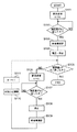
以下、図6(b)の処理を行うための具体的な制御について説明する。図7は、当該排液処理プログラムの制御フローを示す図である。
まず、排液処理がユーザにより設定され、その開始が選択されると、CPU20は主記憶部22から排液処理プログラムを読み込む。そして、まず患者の腹腔から一定の排液を行い、カテーテル、患者ラインe、マニホールド10、チャンバーライン10f、排液ライン10aを排液で満たすことでプライミング処理を行う。Hereinafter, specific control for performing the processing of FIG. 6B will be described. FIG. 7 is a diagram showing a control flow of the drainage processing program.
First, when the drainage process is set by the user and the start is selected, the
その後CPU20は、第一モードとして、排液速度vを比較的速い初期設定値v1に設定し、当該速度v1にてエアシリンダ28を駆動することで排液処理を行う(S101)。このとき、エアシリンダ28はカセット部11の容積(ここでは50mL)を1ストロークとして排出し、当該ストロークの回数に比例して50mL単位で排液を行う。CPU20は、圧力センサ25を介して輸液圧力が所定の第一基準値である陰圧値(x0)に達しない限り、速度v1を維持して排液処理を続ける(S102)。 Thereafter, in the first mode, the
その後、輸液圧力が減圧下において、陰圧値x0に達した場合、CPU20は当該陰圧値x0を記録したストロークにおける排液量を測定する(S103)。ここで当該排液量は、カセット部11の1ストローク分の容積である50mLよりも小さい量である。
前記排液量をカウントした後、CPU20は次にクランプ制御部23を介してクランプk1、k5の開閉状態を反転させ、エアシリンダ28及びエアバルブ24を作動させ、前記カウントした排液量に基づく排液を患者の腹腔内に戻す。これにより圧力センサ24が一定の陽圧値y0を検出するまで腹腔内圧力が上昇する。このとき腹腔内に戻される排液量は50mL以下であるが、前記陽圧値y0に達するには十分な量である。当該陽圧値y0に達したことが検出されると、エアシリンダ動作を停止し、そのまま一定時間(設定値として例えば30秒間)停止を続ける(S104)。この動作により、カテーテル周辺を腹腔が閉塞していれば、当該腹腔が戻された排液により膨らむことで当該閉塞が解消される。また、カテーテル及びチューブが物理的に折れ曲がる等の問題を発生していれば、液の流通が無いことを圧力センサ24によりCPU20が判断することで、駆動を中止する等の対策を取ることができる。なお、ここでは液の流通が完全に停止したことを判断するが、液が一定量まで低下したことを判断するようにしてもよい。Thereafter, when the infusion pressure reaches the negative pressure value x0 under reduced pressure, the
After counting the amount of drainage, the
S104以降が本実施の形態1の主たる特徴部分となる。すなわち、従来であれば、陰圧値x0を検出した時点で排液処理が終了されていたが、本実施の形態1では輸液圧を排液により陽圧値y0に戻した後一定時間停止することで、腹腔が再び膨らみ、カテーテル周辺の閉塞状態が解消されることで、残留している貯留液を再度排液可能にするものである。 S104 and subsequent steps are the main characteristic portions of the first embodiment. That is, in the prior art, the drainage process was terminated when the negative pressure value x0 was detected. However, in the first embodiment, the infusion pressure is returned to the positive pressure value y0 by drainage and then stopped for a certain time. As a result, the abdominal cavity swells again, and the occlusion state around the catheter is eliminated, so that the remaining stored liquid can be drained again.
続いてCPU20は、主記憶部に格納した総積算値Aが自然数の一定値n(図6に示す例ではn=3)に達したか否かを確認する(S105)。nは後述のS111において積算されるので、この時点ではまだ積算されておらず、n=0である。従ってCPU20は、次に第二モードとして、排液速度vを前記v0よりも遅いv1に設定し、排液処理を再開し(S106)、これを輸液圧が第二基準値である陰圧値x0に達するまで行う(S108)。 Subsequently, the
輸液圧が陰圧値x0に達したら、第二モードにおけるサブモードに移行し、CPU20はエアシリンダ28を停止させる。そしてS103と同様に、陰圧値x0を検出したときのストロークにおける排液量を測定する(S109)。その後は前記測定した排液量を患者側に戻し、輸液圧を大気圧とほぼ同等に調整する(S110)。そして、積算値nをインクリメント(n→n+1)して主記憶部22に格納する。その後はS105にて再び総積算値Aを確認し、S106にて排液速度v1で排液を行い、輸液圧が第二基準値である陰圧値x0に至るまで排液処理を行う。つまり、サブモードの内容は<陰圧値x0で一旦停止→大気圧→陰圧値X0へ下降>となる。 When the infusion pressure reaches the negative pressure value x0, the
CPU20は、このS105からS111までの動作を第二モードにおけるサブモードとして、積算値nが総積算値Aに達するまで繰り返す。そして、当該サブモードの繰り返しが終了すれば、当該制御フローに基づく排液処理を終える。
なお、図6(b)に示すプロセスでは、n=3としているが、これ以外の数値(例えばn=1から10のいずれか)であってもよい。しかしながら、良好な排液量を確保し、且つ、患者の負担を最小限に保つためには、n=3程度が好適である。The
In the process shown in FIG. 6B, n = 3, but other numerical values (for example, n = 1 to 10) may be used. However, in order to ensure a good drainage amount and keep the burden on the patient to a minimum, n = 3 is preferable.
また、ここでは第一及び第二基準値を同一値としているが、これは適宜調整が可能である。
<その他の事項>
上記実施の形態では本発明のAPDとして、特許文献1又は図1に示すように、エアシリンダ及びCPUが筐体に一体的に納められ、これにディスポ回路を組み合わせるシステムを用いる例を示した。しかし本発明はこの構成に限定せず、各構成要素を別体としてもよい。例えば、ペリスタルティック式輸液ポンプに輸液チューブを接続し、当該輸液ポンプの駆動制御手段としてPCを接続する構成が挙げられる。Moreover, although the 1st and 2nd reference values are made into the same value here, this can be adjusted suitably.
<Other matters>
In the above embodiment, as an APD of the present invention, as shown in Patent Document 1 or FIG. 1, an example is shown in which an air cylinder and a CPU are integrally housed in a housing, and a system is combined with a disposable circuit. However, the present invention is not limited to this configuration, and each component may be separated. For example, an infusion tube is connected to a peristaltic infusion pump, and a PC is connected as drive control means for the infusion pump.
本発明の自動腹膜灌流装置は、例えば患者が自宅等において、その就寝中に腹膜透析を行い、排液処理をする際に利用することが可能である。 The automatic peritoneal perfusion apparatus of the present invention can be used when, for example, a patient performs peritoneal dialysis while sleeping at home or the like and performs drainage treatment.
Claims (16)
前記制御部は、前記ドライバを介して輸液ポンプを駆動することで第一の排液速度で貯留液の排液処理を行う第一モードと、前記第一の排液速度よりも遅い第二の排液速度で排液処理を行う第二モードとからなる制御モードに基づき制御され、
且つ、所定のタイミングで輸液ポンプの輸液圧を第一圧まで高めた後に、第一モードから第二モードへ切り替える制御モード切替手段を備える構成である
ことを特徴とする自動腹膜灌流装置。An automatic peritoneal perfusion device comprising an infusion pump for transfusing fluid stored in the abdominal cavity of a patient outside the body, a driver for the infusion pump, and a control unit connected to the driver,
The control unit drives the infusion pump via the driver to perform a first mode for draining the stored liquid at a first drainage speed, and a second mode slower than the first drainage speed. It is controlled based on a control mode consisting of a second mode for performing drainage processing at a drainage speed,
An automatic peritoneal perfusion device comprising control mode switching means for switching from the first mode to the second mode after increasing the infusion pressure of the infusion pump to the first pressure at a predetermined timing.
ことを特徴とする請求項1に記載の自動腹膜灌流装置。The control mode switching means is configured to perform switching based on any of the drainage amount for the drainage treatment, the infusion pressure in the infusion pump, and the drainage treatment time reaching a predetermined judgment value. The automatic peritoneal perfusion device according to claim 1, wherein
前記制御部は前記第一モードにおいて、排液処理にかかる輸液圧が第一基準値まで下降したことが前記圧力計測手段により検出されるまで排液処理を行い、
前記検出後は、輸液圧を第一圧まで高め、一旦停止後、当該輸液圧が前記第一基準値よりも低い第二基準値に下降するまで排液処理を継続する
ことを特徴とする請求項1に記載の自動腹膜灌流装置。Furthermore, the device comprises pressure measuring means for detecting the infusion pressure of the infusion pump,
In the first mode, the control unit performs drainage processing until it is detected by the pressure measuring means that the infusion pressure applied to the drainage processing has decreased to the first reference value,
After the detection, the infusion pressure is increased to the first pressure, and once stopped, the drainage process is continued until the infusion pressure falls to a second reference value lower than the first reference value. Item 2. An automatic peritoneal perfusion device according to Item 1.
各サブモードでは、前記制御部は輸液圧が第二基準値に達した後一旦停止し、その後は第二圧まで上昇させ、再度、第二基準値に下降されるまで排液処理を継続し、
第二基準値到達後は、輸液圧を第二圧に高め、一旦停止後、第二基準値に下降するまで排液処理を継続する構成である
ことを特徴とする請求項3に記載の自動腹膜灌流装置。The second mode contains multiple submodes,
In each sub-mode, the control unit temporarily stops after the infusion pressure reaches the second reference value, then increases to the second pressure, and continues the drainage process until the infusion pressure is decreased to the second reference value again. ,
4. The automatic operation according to claim 3, wherein after the second reference value is reached, the infusion pressure is increased to the second pressure, and after the suspension, the drainage process is continued until the infusion pressure is lowered to the second reference value. Peritoneal perfusion device.
ことを特徴とする請求項3に記載の自動腹膜灌流装置。The automatic peritoneal perfusion device according to claim 3, wherein the first pressure is a positive pressure.
ことを特徴とする請求項4に記載の自動腹膜灌流装置。The automatic peritoneal perfusion device according to claim 4 , wherein the second pressure is substantially atmospheric pressure.
駆動時の当該エアシリンダの各ストロークに対応して輸液が一定量ごとに行われる構成であって、
前記制御部は、圧力計測手段により前記第一基準値が検出された時点のストローク中における輸液量を測定し、
当該測定した輸液量以下の量の輸液を腹腔内に戻すことで輸液圧が前記第一圧に調整される構成である
ことを特徴とする請求項3に記載の自動腹膜灌流装置。The infusion pump is an air cylinder;
The infusion is performed for each fixed amount corresponding to each stroke of the air cylinder at the time of driving,
The control unit measures the infusion volume during the stroke at the time when the first reference value is detected by the pressure measuring means,
The automatic peritoneal perfusion device according to claim 3, wherein the infusion pressure is adjusted to the first pressure by returning an infusion of an amount equal to or less than the measured infusion amount.
当該チャンバーでは、中空の筐体に、気体が導入排出される気体開口部と、液体が吸入排出される液体開口部とが、可撓性隔膜を介して配されており、
輸液ポンプは前記チャンバーの気体開口部に対して装着され、駆動時に当該輸液ポンプの駆動力が気体開口部からチャンバー内に及ぶことで可撓性隔膜が変形し、液体開口部を通じて輸液がなされる構成である
ことを特徴とする請求項1に記載の自動腹膜灌流装置。The infusion pump is configured such that an infusion circuit in which an infusion tube and a chamber are connected is mounted in the chamber,
In the chamber, a gas opening through which gas is introduced and discharged and a liquid opening through which liquid is sucked and discharged are arranged in a hollow housing via a flexible diaphragm,
The infusion pump is attached to the gas opening of the chamber, and the driving force of the infusion pump extends from the gas opening to the chamber during driving, whereby the flexible diaphragm is deformed and infusion is performed through the liquid opening. The automatic peritoneal perfusion device according to claim 1, wherein the peritoneal perfusion device is configured.
第一モードでは、制御部に前記ドライバを介して輸液ポンプを駆動させることで第一の排液速度で貯留液の排液処理を行い、
所定のタイミングで輸液ポンプの輸液圧を第一圧まで高めた後に、第一モードから第二モードへ切り替え、
第二モードでは前記第一の排液速度よりも遅い第二の排液速度で排液処理を行う
ことを特徴とする排液制御プログラム。A drainage control program for an automatic peritoneal perfusion apparatus comprising an infusion pump for transfusing fluid stored in the abdominal cavity of a patient outside the body, a driver for the infusion pump, and a control unit connected to the driver,
In the first mode, the controller performs drainage treatment of the stored liquid at the first drainage speed by driving the infusion pump via the driver,
After increasing the infusion pressure of the infusion pump to the first pressure at a predetermined timing, switch from the first mode to the second mode,
A drainage control program, wherein in the second mode, drainage treatment is performed at a second drainage rate that is slower than the first drainage rate.
ことを特徴とする請求項9に記載の自動腹膜灌流装置の排液制御プログラム。The control unit uses, as the determination criterion for the switching, that any one of a drainage amount for the drainage treatment, an infusion pressure in the infusion pump, and a drainage treatment time has reached a predetermined judgment value. The drainage control program for an automatic peritoneal perfusion device according to claim 9.
前記制御部は前記第一モードにおいて、排液処理にかかる輸液圧が第一基準値まで下降したことが前記圧力計測手段により検出されるまで排液処理を行い、
前記検出後は、輸液圧を第一圧まで高め、一旦停止後、当該輸液圧が前記第一基準値よりも低い第二基準値に達するまで排液処理を継続する
ことを特徴とする請求項9に記載の自動腹膜灌流装置の排液制御プログラム。The apparatus comprises pressure measuring means for detecting the infusion pressure of the infusion pump,
In the first mode, the control unit performs drainage processing until it is detected by the pressure measuring means that the infusion pressure applied to the drainage processing has decreased to the first reference value,
The infusion pressure is increased to the first pressure after the detection, and after the suspension, the drainage process is continued until the infusion pressure reaches a second reference value lower than the first reference value. A drainage control program for an automatic peritoneal perfusion device according to claim 9.
当該各サブモードでは、前記制御部に対し輸液圧が第二基準値に達した後一旦停止し、その後は第二圧まで上昇させ、再度、第二基準値に下降されるまで排液処理を継続し、
第二基準値到達後は、輸液圧を第二圧に高め、一旦停止後、第二基準値に下降するまで排液処理を継続する
ことを特徴とする請求項11に記載の自動腹膜灌流装置の排液制御プログラム。In the second mode, multiple submodes are executed,
In each of the sub modes, once the infusion pressure reaches the second reference value for the control unit, it is temporarily stopped, and then the second pressure is increased to the second pressure value, and the drainage treatment is performed again until the control pressure is lowered to the second reference value. It continued,
After the second reference value reaches increases the infusion pressure to the second pressure, once after stopping, the automatic peritoneal dialysis apparatus according to claim 11, characterized by continuing the draining process until drops to a second reference value Drainage control program .
ことを特徴とする請求項11に記載の自動腹膜灌流装置の排液制御プログラム。The drainage control program for an automatic peritoneal perfusion device according to claim 11, wherein the first pressure is a positive pressure.
ことを特徴とする請求項12に記載の自動腹膜灌流装置の排液制御プログラム。The drainage control program for an automatic peritoneal perfusion device according to claim 12 , wherein the second pressure is substantially atmospheric pressure.
駆動時の当該エアシリンダの各ストロークに対応して輸液が一定量ごとに行われる構成であって、
前記第一モードでは、前記制御部に対し、圧力計測手段により前記第一基準値を検出した時点のストローク中における輸液量を測定させ、
当該測定した輸液量以下の量の輸液を腹腔内に戻させることで輸液圧を第一圧まで高める
ことを特徴とする請求項11に記載の自動腹膜灌流装置の排液制御プログラム。The infusion pump is an air cylinder;
The infusion is performed for each fixed amount corresponding to each stroke of the air cylinder at the time of driving,
In the first mode, the control unit is allowed to measure the infusion volume during the stroke when the first reference value is detected by the pressure measuring means,
The infusion control program for an automatic peritoneal perfusion apparatus according to claim 11, wherein the infusion pressure is increased to the first pressure by returning an infusion of an amount equal to or less than the measured infusion volume.
当該チャンバーでは、中空の筐体に、気体が導入排出される気体開口部と、液体が吸入排出される液体開口部とが、可撓性隔膜を介して配されており、
輸液ポンプは前記チャンバーの気体開口部に対して装着され、駆動時に当該輸液ポンプの駆動力が気体開口部からチャンバー内に及ぶことで可撓性隔膜が変形し、液体開口部を通じて輸液がなされる構成である
ことを特徴とする請求項9に記載の自動腹膜灌流装置の排液制御プログラム。The infusion pump is configured such that an infusion circuit in which an infusion tube and a chamber are connected is mounted in the chamber,
In the chamber, a gas opening through which gas is introduced and discharged and a liquid opening through which liquid is sucked and discharged are arranged in a hollow housing via a flexible diaphragm,
The infusion pump is attached to the gas opening of the chamber, and the driving force of the infusion pump extends from the gas opening to the chamber during driving, whereby the flexible diaphragm is deformed and infusion is performed through the liquid opening. The drainage control program for an automatic peritoneal perfusion device according to claim 9, wherein the program is a configuration .
Priority Applications (1)
| Application Number | Priority Date | Filing Date | Title |
|---|---|---|---|
| JP2006545180A JP4715751B2 (en) | 2004-11-18 | 2005-11-18 | Automatic peritoneal perfusion device and its drainage control method |
Applications Claiming Priority (4)
| Application Number | Priority Date | Filing Date | Title |
|---|---|---|---|
| JP2004333984 | 2004-11-18 | ||
| JP2004333984 | 2004-11-18 | ||
| PCT/JP2005/021292 WO2006054720A1 (en) | 2004-11-18 | 2005-11-18 | Automatic peritoneal dialyzer and method of drainage control therefor |
| JP2006545180A JP4715751B2 (en) | 2004-11-18 | 2005-11-18 | Automatic peritoneal perfusion device and its drainage control method |
Publications (2)
| Publication Number | Publication Date |
|---|---|
| JPWO2006054720A1 JPWO2006054720A1 (en) | 2008-06-05 |
| JP4715751B2 true JP4715751B2 (en) | 2011-07-06 |
Family
ID=36407256
Family Applications (1)
| Application Number | Title | Priority Date | Filing Date |
|---|---|---|---|
| JP2006545180A Expired - Fee Related JP4715751B2 (en) | 2004-11-18 | 2005-11-18 | Automatic peritoneal perfusion device and its drainage control method |
Country Status (2)
| Country | Link |
|---|---|
| JP (1) | JP4715751B2 (en) |
| WO (1) | WO2006054720A1 (en) |
Families Citing this family (8)
| Publication number | Priority date | Publication date | Assignee | Title |
|---|---|---|---|---|
| BRPI0806221A2 (en) * | 2007-02-09 | 2011-09-06 | Kci Licensing Inc | apparatus for managing the reduced pressure in a fabric site and method for managing the reduced pressure in a fabric site |
| GR20110100184A (en) | 2011-03-28 | 2012-09-15 | Αχιλλεας Τσουκαλης | Liquid-exchanging system for medical use |
| CN102614575B (en) * | 2012-04-28 | 2013-06-12 | 山东赛克赛斯药业科技有限公司 | Composite flexible drainage device |
| DK3206733T3 (en) | 2014-10-17 | 2020-06-08 | Debiotech Sa | DELIVERY SYSTEM AND OPERATING MODE |
| CN109045385A (en) * | 2018-09-15 | 2018-12-21 | 吉林省迈达医疗器械股份有限公司 | A kind of peritoneal dialysis machine |
| EP4157392B1 (en) * | 2020-05-27 | 2024-02-28 | Baxter International Inc. | Peritoneal dialysis using pressurized cylinder |
| US11717600B2 (en) * | 2020-06-04 | 2023-08-08 | Fresenius Medical Care Holdings, Inc. | Administering dialysis treatment using a hybrid automated peritoneal dialysis system |
| US20230285649A1 (en) * | 2020-06-05 | 2023-09-14 | Baxter International Inc. | Automated peritoneal dialysis using bellows |
Citations (3)
| Publication number | Priority date | Publication date | Assignee | Title |
|---|---|---|---|---|
| JPH07275357A (en) * | 1994-04-15 | 1995-10-24 | Terumo Corp | Dialysis fluid exchanging device |
| JPH10174715A (en) * | 1996-12-16 | 1998-06-30 | Jms Co Ltd | Automatic peritoneum dializing device |
| JPH10211276A (en) * | 1997-01-30 | 1998-08-11 | Jms Co Ltd | Automatic liquid supply/discharge device for peritoneal dialyser, and automatic peritoneal dialyser using the device |
Family Cites Families (2)
| Publication number | Priority date | Publication date | Assignee | Title |
|---|---|---|---|---|
| CA2042449C (en) * | 1991-05-13 | 1997-02-04 | Joseph E. Dadson | Peritoneal dialysis apparatus |
| JP3453270B2 (en) * | 1997-02-28 | 2003-10-06 | テルモ株式会社 | Peritoneal dialysis machine |
-
2005
- 2005-11-18 WO PCT/JP2005/021292 patent/WO2006054720A1/en not_active Application Discontinuation
- 2005-11-18 JP JP2006545180A patent/JP4715751B2/en not_active Expired - Fee Related
Patent Citations (3)
| Publication number | Priority date | Publication date | Assignee | Title |
|---|---|---|---|---|
| JPH07275357A (en) * | 1994-04-15 | 1995-10-24 | Terumo Corp | Dialysis fluid exchanging device |
| JPH10174715A (en) * | 1996-12-16 | 1998-06-30 | Jms Co Ltd | Automatic peritoneum dializing device |
| JPH10211276A (en) * | 1997-01-30 | 1998-08-11 | Jms Co Ltd | Automatic liquid supply/discharge device for peritoneal dialyser, and automatic peritoneal dialyser using the device |
Also Published As
| Publication number | Publication date |
|---|---|
| JPWO2006054720A1 (en) | 2008-06-05 |
| WO2006054720A1 (en) | 2006-05-26 |
Similar Documents
| Publication | Publication Date | Title |
|---|---|---|
| AU2021201070B2 (en) | Systems, devices and methods for draining and analyzing bodily fluids | |
| JP4715751B2 (en) | Automatic peritoneal perfusion device and its drainage control method | |
| KR102431007B1 (en) | Pneumatically coupled fluid control system and process with air detection and elimination | |
| US8784359B2 (en) | Cassette system for peritoneal dialysis machine | |
| US20090043240A1 (en) | Method and apparatus for blood transport using a pressure controller in measurement of blood characteristics | |
| US20220080117A1 (en) | Systems and methods for incorporating patient pressure into medical fluid delivery | |
| JP2003293960A (en) | Instantaneous volume measurement system and method for noninvasive liquid parameter measurement | |
| EP2111242A1 (en) | System and method for peritoneal dialysis | |
| CA3138944A1 (en) | Patient line check and occlusion detection for a dialysis machine using adjusted pump operating parameters | |
| US11911548B2 (en) | Peritoneal dialysis system including manifold assembly and peristaltic pump | |
| JP2024521249A (en) | Measurement of urine production and other urinary parameters | |
| CN215841098U (en) | Pressure measuring device and urine dynamic instrument | |
| US20240042113A1 (en) | Manifold assembly for a peritoneal dialysis apparatus and peritoneal dialysis apparatus comprising said manifold assembly | |
| WO2022122941A1 (en) | Manifold assembly for a peritoneal dialysis apparatus and peritoneal dialysis apparatus comprising said manifold assembly |
Legal Events
| Date | Code | Title | Description |
|---|---|---|---|
| A621 | Written request for application examination |
Free format text: JAPANESE INTERMEDIATE CODE: A621 Effective date: 20081030 |
|
| A131 | Notification of reasons for refusal |
Free format text: JAPANESE INTERMEDIATE CODE: A131 Effective date: 20101102 |
|
| A521 | Request for written amendment filed |
Free format text: JAPANESE INTERMEDIATE CODE: A523 Effective date: 20101221 |
|
| A01 | Written decision to grant a patent or to grant a registration (utility model) |
Free format text: JAPANESE INTERMEDIATE CODE: A01 Effective date: 20110301 |
|
| A61 | First payment of annual fees (during grant procedure) |
Free format text: JAPANESE INTERMEDIATE CODE: A61 Effective date: 20110314 |
|
| R150 | Certificate of patent or registration of utility model |
Free format text: JAPANESE INTERMEDIATE CODE: R150 |
|
| FPAY | Renewal fee payment (event date is renewal date of database) |
Free format text: PAYMENT UNTIL: 20140408 Year of fee payment: 3 |
|
| R250 | Receipt of annual fees |
Free format text: JAPANESE INTERMEDIATE CODE: R250 |
|
| LAPS | Cancellation because of no payment of annual fees |