JP4712151B2 - Light amount adjusting device for microscope and laser scanning microscope - Google Patents
Light amount adjusting device for microscope and laser scanning microscope Download PDFInfo
- Publication number
- JP4712151B2 JP4712151B2 JP2000102275A JP2000102275A JP4712151B2 JP 4712151 B2 JP4712151 B2 JP 4712151B2 JP 2000102275 A JP2000102275 A JP 2000102275A JP 2000102275 A JP2000102275 A JP 2000102275A JP 4712151 B2 JP4712151 B2 JP 4712151B2
- Authority
- JP
- Japan
- Prior art keywords
- light
- laser
- microscope
- amount
- deflecting
- Prior art date
- Legal status (The legal status is an assumption and is not a legal conclusion. Google has not performed a legal analysis and makes no representation as to the accuracy of the status listed.)
- Expired - Fee Related
Links
Images


Description
【0001】
【発明の属する技術分野】
本発明は、例えば走査型顕微鏡や光学顕微鏡などに用いられる顕微鏡用光量調整装置及びレーザ走査型顕微鏡に関するものである。
【0002】
【従来の技術】
従来、走査型顕微鏡の光源として、レーザ光を発生するレーザ光源装置が用いられているが、このようなレーザ光源装置は、構造的に大型であるため、顕微鏡本体に直接取付けることが困難な場合がある。
【0003】
そこで、従来では、レーザ発生源のレーザ共振器と顕微鏡本体の間を光ファイバにより結合し、レーザ共振器から発したレーザ光を集光レンズにより光ファイバの入射端に集光させ、光ファイバの出射端に配置されたコリメータレンズを介して顕微鏡本体内部の光偏向機構に進めるようにしている。
【0004】
ところで、走査型顕微鏡に供給されるレーザ光は、必要に応じて光量を可変できることが好ましく、このため、従来では、光ファイバへの入射端の集光レンズの前または後に光量調整装置として可変光減衰器を配置し、この可変光減衰器により光ファイバへ入射させるレーザ光の光量を変化させることで、必要に応じた光量のレーザ光を走査型顕微鏡に供給する方法が考えられている。
【0005】
この場合、可変光減衰器としては、複数の固定減衰フィルタを回転体に取付け、この回転体を回転させて、所望する固定減衰フィルタを光路上に位置させることで、光量を変化させるもの、複数の固定減衰フィルタを直線体に一列に取付け、この直線体をスライドさせて、所望する固定減衰フィルタを光路上に位置させるもの、あるいは、円板状のガラス板の円周方向に沿って順次透過率が異なるように金属膜を蒸着させ、このガラス板を回転させることで、連続して光量を変化させるようにしたものなどが用いられる。
【0006】
一方、光ファイバへ入射させるレーザ光の光量を最大、最小の間で断続的に切換えるような場合、可変光減衰器の一種としてシャッタが用いられており、このようなシャッタ機能を有するものとして、例えば、特開平11−232122号公報に開示されるような音響光学素子(AOTF)が用いられている。
【0007】
【発明が解決しようとする課題】
ところが、複数の固定減衰フィルタを使用したものによると、光路上に位置される固定減衰フィルタを選択するようにしているため、光量を段階的に可変することはできるが、連続的に光量を変化させるには、多くのフィルタを必要とするとともに、回転機構またはスライド機構を要することから、可変光減衰器全体が大型化して大きなスペースを必要とし、また、光量の変化速度を高速化することも難しいという問題があった。
【0008】
また、円板状のガラス板に金属膜を蒸着させたものは、滑らかに減衰能を変化させることはできるが、回転機構を要することから、やはり大型化するとともに、光量の変化速度を高速化することのが難しいという問題があった。
【0009】
一方、レーザ走査型顕微鏡では、UV域から赤外域までの複数の波長の光源を選択的に使用することが多く、しかも、特定波長については、レーザ光を高速で断続的に切換えるという要求があるとともに、光路遮断のときは、完全に光量を0にできることが必要である。ところが、上述のシャッタとして用いられる音響光学素子(AOTF)では、構造上の問題から完全に光量0にできないという問題があった。
【0010】
本発明は上記事情に鑑みてなされたもので、高速な光量調整が可能で且つ断続制御が可能な顕微鏡用光量調整装置及びレーザ走査型顕微鏡を提供することを目的とする。
【0011】
【課題を解決するための手段】
請求項1記載の発明は、光源から出射される光の光量を調整して顕微鏡本体に供給する顕微鏡用光量調整装置において、前記光源からの前記光の径を拡大しかつ平行光にするビームエキスパンダと、前記ビームエキスパンダを経由して前記光源からの前記光が平行光となる位置に配置され、偏向方向を各々独立して制御可能な微小光偏向素子を面状に多数配列した光偏向手段と、前記光偏向手段の前記多数の微小光偏向素子で照明光路上に偏向した前記光源からの光を集光する集光光学系と、前記集光光学系の集光位置に内部で集光された光を散乱させて前記顕微鏡本体に供給する光学系と、前記多数の微小光偏向素子の偏向方向を各々独立して制御して前記光源からの前記光を偏向する割合を調整し、前記光源からの前記光を前記照明光路上と該照明光路外との各方向に偏向し、前記光源からの光の光量を調整する制御手段と、前記制御手段の制御により前記照明光路外に偏向された光が、前記照明光路上に混入するのを防止する手段とを具備したことを特徴としている。
【0012】
請求項2記載の発明は、請求項1記載の発明において、前記内部で集光された光を散乱させる光学系は、光ファイバであることを特徴としている。
【0013】
請求項3の発明は、請求項2記載の発明において、前記光ファイバは、シングルモードファイバであることを特徴としている。
【0014】
請求項4の発明は、請求項1記載の発明において、前記内部で集光された光を散乱させる光学系は、光散乱板であることを特徴としている。
【0015】
請求項5の発明は、請求項1記載の発明において、前記光偏向手段は、前記微小光偏向素子として前記微小ミラーを同一平面上に格子状に多数配列し、これら微小ミラーの偏向方向を各々独立して制御可能な微小ミラーアレイであることを特徴としている。
【0016】
請求項6の発明は、請求項1又は5記載の発明において、前記光偏向手段の前記多数の微小光偏向素子を制御して調整した前記光源からの前記光の光量を検出する光量検出手段を備え、前記制御手段は、前記光量検出手段により検出された前記光量と予め設定された設定光量とを比較し、その結果に基づいて前記光偏向手段の前記多数の微小光偏向素子の各偏向方向を各々独立して制御することを特徴としている。
【0017】
請求項7の発明は、請求項1の発明において、前記光偏向手段は、正立型顕微鏡または倒立型顕微鏡における照明光路の開口絞りの位置に配置されていることを特徴としている。
【0018】
請求項8の発明は、請求項7の発明において、前記光源は、ランプ光源であり、前記制御手段は、前記ランプ光源のフィラメント電圧が一定のまま、前記多数の微小光偏向素子の制御を行うことによって照明光の光量調整を行うことを特徴としている。
【0019】
請求項9の発明は、レーザ光源と、前記レーザ光源からのレーザ光のビーム径を拡大しかつ平行光にするビームエキスパンダと、前記ビームエキスパンダを経由して前記レーザ光源からの前記レーザ光が平行光平行光となる位置に配置され、偏向方向が各々独立して制御可能な微小光偏向素子を面状に多数配列した光偏向手段と、照明光路上と該照明光路外との方向に前記光偏向手段の微小光偏向素子で前記レーザ光源からの前記レーザ光を偏向するために前記微小光偏向素子を各々独立して制御する制御手段と、前記微小光偏向素子によって照明光路上に偏向された前記レーザ光を集光する集光光学系と、前記集光光学系の集光位置に配置されるシングルモード光ファイバと、前記シングルモード光ファイバから出射される前記レーザ光が供給され、当該レーザ光を2次元走査するスキャナと前記レーザ光の走査により発生する試料からの光を検出する光検出器を有する走査型顕微鏡本体とを具備し、前記制御手段による微小光偏向素子の各々独立した制御により、前記レーザ光源からの前記レーザ光を偏向する割合を調整し、前記走査型顕微鏡本体に供給される前記レーザ光の光量を調整することを特徴としている。
請求項10の発明は、請求項9の発明において、前記レーザ光源は、互いに異なる波長のレーザ光を発生する複数のレーザ光源であり、前記光偏向手段は、前記複数のレーザ光源のそれぞれに対応して設けられ、前記制御手段は、前記各光偏向手段を個別に制御することにより、前記レーザ光が波長ごとに光量を調整されて、前記シングルモード光ファイバによって前記走査型顕微鏡本体に供給されることを特徴としている。
請求項11の発明は、請求項9の発明において、前記微小ミラーアレイで反射した照明光路には、前記絞り、前記集光レンズおよび前記光ファイバの入射端が配置されている。
【0020】
この結果、本発明によれば、光偏向手段の個々の微小光偏向素子の数、位置について、それぞれ独立して偏向方向を制御し光源からの光を偏向する割合を調整することにより、光量の増減を高速で調整でき、また、光量を最大、最小の間で断続的に切換えるシャッタとして用いる場合も、高速で切換える動作が可能である。
【0021】
また、本発明によれば、光偏向手段の微小光偏向素子の偏向方向を、予め設定された設定光量を用いて制御することにより、設定光量に応じた光量に調整することができる。
【0022】
【発明の実施の形態】
以下、本発明の実施の形態を図面に従い説明する。
【0023】
(第1の実施の形態)
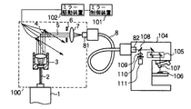
図1は、本発明の光量調整装置が適用されるレーザ走査型顕微鏡の概略構成を示している。図において、1はレーザ共振器からなるレーザ発生源で、このレーザ発生源1は、平行光束からなるレーザ光を出射するものである。そして、このレーザ発生源1からのレーザ光の出射光路2には、ビームエキスパンダ3および光偏向手段として微小ミラーアレイ4とを備えた光量調整装置100が配置されている。
【0024】
ビームエキスパンダ3は、平行光束からなるレーザ光のビーム径を拡大するビーム拡大光学系からなるものである。微小ミラーアレイ4は、ビームエキスパンダ3を経由してビーム径が拡大された平行光束上に配置されており、ビーム径が拡大されたレーザ光が微小ミラーアレイ4に投影される。
【0025】
ここで、微小ミラーアレイ4について説明すると、かかる微小ミラーアレイ4は、半導体プロセスなどのマイクロプロセスにより製作されるもので、ここでは、図2に示すように同一平面上に微小光偏向素子として多数の微小ミラー41が格子状に整列されており、あたかも一枚の平面鏡のようになっている。この場合、各微小ミラー41自体の構成は、種々あるが、例えば、それぞれ独立して両端を回動自在に支持され、電磁力や静電力などの作用力により、両端の支持を中心に、図3(a)の状態から同図(b)の状態に回動可能になっている。これら微小ミラー41は、回動方向を一個一個独立して、またはグループ単位で悉無的に制御することにより微小ミラーアレイ4全体に投射されたレーザ光の反射光量を変化可能にしている。つまり、反射光の偏向方向を変化させる微小ミラー41を選択してレーザ発生源1からのレーザ光を偏向する微小ミラー41の割合を調整することにより、選択された微小ミラー41の数に比例して反射光量を減衰させることができるので、このときの選択数を設定するのみで、連続的にレーザ発生源1からのレーザ光の光量を変化させることができる。微小ミラーアレイ4には、微小ミラーアレイ4の微小ミラー41の偏向方向を各々独立した駆動制御を行うためのミラー制御装置101がミラー駆動装置102を介して接続されている。
【0026】
微小ミラーアレイ4で反射した照明光路5には、絞り6、集光レンズ7および光ファイバ8の入射端81が配置されている。絞り6は、照明光路外に微小ミラー41で偏向された軸外光103を遮断して、集光レンズ7に照明光路外の軸外光103が入射してレーザ光の光量調整に影響を与えることを防止するためのものである。集光レンズ7は、絞り6を介して入射されるレーザ光を光ファイバ8の入射端81に集光させるものである。そして、光ファイバ8は、出射端82より出射されるレーザ光を被光源供給装置である走査型顕微鏡本体104側に供給するようにしている。
【0027】
ここで、走査型顕微鏡本体104の構成について簡単に説明する。
【0028】
走査型顕微鏡本体104は、出射軸82より供給したレーザ光を2次元走査するためのX−Yスキャナ105、X−Yスキャナ105で2次元走査されたレーザ光を試料106に照射する対物レンズ107、試料106から対物レンズ107、X−Yスキャナ105を介して同一光路を戻ってきた光、例えば蛍光を分割するダイクロイックミラー108、ダイクロイックミラー108で反射した蛍光を集光レンズ109で集光し、その集光位置に配置された絞り110および絞り110を通過した光を検出する光検出器111から構成されている。
【0029】
次に、以上のように構成した実施の形態の動作を説明する。
【0030】
いま、レーザ発生源1より、平行光束からなるレーザ光が出射すると、このレーザ光は、ビームエキスパンダ3によりビーム径が拡大され、微小ミラーアレイ4に投影される。
【0031】
レーザ光は、微小ミラーアレイ4で反射され、絞り6、集光レンズ7を介して光ファイバ8の入射端81に入射される。
【0032】
光ファイバ8の入射端81に入射されたレーザ光は、光ファイバ8を通り、出射端82より走査型顕微鏡本体104内に導かれる。
【0033】
走査型顕微鏡本体104内では、レーザ光がダイクロイックミラー108を介してX−Yスキャナ105に導かれ、2次元走査される。
【0034】
X−Yスキャナ105で2次元走査されたレーザ光は、対物レンズ107で集光され、試料106上を2次元走査される。、
次いで、試料106からの光、例えば蛍光は、光路を逆に戻り、対物レンズ107、X−Yスキャナ105を介してダイクロイックミラー108で反射される。
【0035】
ダイクロイックミラー108で反射された光は、集光レンズ109で集光され、絞り110を介して光検出器111で検出され、不図示の画像処理装置で画像処理され顕微鏡画像が得られる。
【0036】
ここで、光ファイバ8の入射端81へのレーザ光の入射量を最大にする場合について、以下に説明する。
【0037】
まず、ミラー制御装置101で、微小ミラーアレイ4の全ての微小ミラー41を図3(a)に示すような状態になるように設定する。これによりビームエキスパンダ3より微小ミラーアレイ4に入射されるレーザ光の全光量が同一方向、ここでは、照明光路5に偏向され、絞り6、集光レンズ7を介して光ファイバ8の入射端81に最大光量のレーザ光が入射される。
【0038】
一方、光ファイバ8の入射端81へのレーザ光の入射量を調整する場合について、以下に説明する。
【0039】
まず、ミラー制御装置101で微小ミラーアレイ4の任意の微小ミラー41について、電磁力や静電力などの作用力を用いて回動させ、これら微小ミラー41を図3(b)に示すような回動状態になるように設定する。この場合、図2に示す微小ミラーアレイ4の微小ミラー41中で黒く塗り潰したものが図3(b)の状態にあるものを表わしている。
【0040】
すると、このように設定された微小ミラー41で偏向されるレーザ光は、これまでと異なる方向(照明光路外)に偏向され、これら偏向された光(軸外光103)は、絞り6で遮光することによって光路調整したレーザ光の照明光路5に含まれないようにし、集光レンズ7に投影されない。つまり、微小ミラーアレイ4中の一部の微小ミラー41を回動させて、その反射光の偏向を異なる方向に設定し、集光レンズ7に投影される光量を減らすことで、光ファイバ8の入射端81に光量調整されたレーザ光が入射される。
【0041】
従って、このようにすれば、微小ミラーアレイ4の各微小ミラー41は、その数、位置について、それぞれ独立して回動制御、すなわち偏向制御できるので、図3(b)に示す回動状態にある微小ミラー41を増加するにしたがって、集光レンズ7に投影される光量が減少して減光される。また、全ての微小ミラー41を偏向状態に設定すれば、集光レンズ7に投影される光量は全くなくなるので、シャッタ機能も得られる。この場合、微小ミラーアレイ4は、電磁力や静電力などの作用力を用いて微小ミラー41を回動制御するものであり、回動による偏向によって光量の増減が高速で調整可能である。また、光量を最大、最小の間で断続的に切換えるシャッタとして用いる場合も、高速で切換える動作が可能であることは勿論、完全に光量0の状態に高速にきりかえることもできる。
【0042】
(第2の実施の形態)
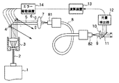
図4は、本発明の第2の実施の形態の概略構成を示すもので、図1と同一部分には、同符号を付している。
【0043】
この場合、光ファイバ8の出射端82より出射されるレーザ光の出射光路9には、コリメータレンズ10、ハーフミラー11が配置されている。コリメータレンズ10は、光ファイバ8からのレーザ光を平行光束のレーザ光に変換するものである。ハーフミラー11は、コリメータレンズ10からのレーザ光の一部を透過して図示しないレーザ走査型顕微鏡本体に入射させるとともに、残りの一部を反射して光量検出器12に入射させるようにしている。光量検出器12は、光ファイバ8の出射端82より出射されるレーザ光の光量を検出するものである。
【0044】
光量検出器12には、演算装置13が接続されている。この演算装置13は、図示しないメモリに、予め設定される設定光量と光量検出器12より検出される光量とを外部入力として用い、例えば、これら光量を比較し、この比較結果から微小ミラーアレイ4のうち回動動作させる微小ミラー41の数や位置を決定し、ミラー駆動装置14を介してそれぞれの微小ミラー41を制御するようにしている。
【0045】
このようにすれば、光ファイバ8の出射端82より出射されるレーザ光の光量は、光量検出器12により検出され、演算装置13において、予め設定された設定光量と比較される。そして、この比較結果から微小ミラーアレイ4のうち回動動作させる微小ミラー41の数や位置が決定され、ミラー駆動装置14を介してそれぞれの微小ミラー41が制御される。
【0046】
従って、微小ミラーアレイ4で反射されるレーザ光は、予め設定された設定光量を用いて光量調整されるので、光ファイバ8の出射端82からは、設定光量に応じた光量のレーザ光を出射することができる。
【0047】
なお、光量検出器12は、集光レンズ7の前に配置しても、上述したと同様な効果を期待できる。
【0048】
(第3の実施の形態)
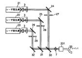
ところで、レーザ走査型顕微鏡では、例えばUV域から赤外域までの複数の波長の光源を使用することがある。図5は、このようなレーザ走査型顕微鏡に適用される光源装置の概略構成を示すものである。
【0049】
図において、21、22、23は、レーザ発生源で、これらレーザ発生源21、22、23は、波長の異なるレーザ光を出射するものである。図示例では、レーザ発生源21はUVレーザ、レーザ発生源22は赤色レーザ、レーザ発生源23は青色レーザを出射する。
【0050】
これらレーザ発生源21、22、23からのレーザ光のそれぞれの出射光路には、ビームエキスパンダ3を各々介して微小ミラーアレイ24、25、26が配置されている。これらビームエキスパンダ3と微小ミラーアレイ24、25、26は、第1の実施の形態で述べたと同様の構成をなすものである。
【0051】
また、微小ミラーアレイ24、25、26のそれぞれの反射光路には、絞り27、28、29を介してハーフミラー30、31および反射ミラー32が配置されている。
【0052】
そして、反射ミラー32の反射光路上には、ハーフミラー31、30および集光レンズ7を介して光ファイバ33の入射端331が配置される。微小ミラーアレイ24からの反射光は、ハーフミラー30で反射させて光ファイバ33の入射端331に集光するようになっており、また、微小ミラーアレイ25からの反射光は、ハーフミラー31で反射させ、ハーフミラー30を透過させて光ファイバ33の入射端331に集光するようになっている。また、微小ミラーアレイ26からの反射光は、反射ミラー32で反射させ、ハーフミラー31、30を透過させて光ファイバ33の入射端331に集光するようになっている。
【0053】
このような構成において、レーザ走査型顕微鏡側の要求により、例えば、レーザ発生源21のみを使用する場合は、微小ミラーアレイ24について、全ての微小ミラーを図3(a)に示すような状態に設定して、レーザ発生源21からのレーザ光を同一方向に偏向させ、ハーフミラー30で反射し、集光レンズ7を介して光ファイバ33の入射端331にそれぞれ入射させる。また、残りの微小ミラーアレイ25、26については、全ての微小ミラーを図3(b)に示すような回動状態に設定し、これら微小ミラーで反射されるレーザ光を全て異なる方向に偏向させ、絞り28、29の通過を皆無にすることにより、光ファイバ33の入射端331への入射光量を0にする。
【0054】
また、この状態で、微小ミラーアレイ24の任意の微小ミラーを回動させて、その反射光を異なる方向に設定すれば、光ファイバ33の出射端331への入射光量を調整することができる。また、全ての微小ミラーを同時に回動状態に設定すれば、光ファイバ33の入射端331への入射光量を0にすることもでき、さらに、全ての微小ミラーを、図3(a)に示す状態と、同図(b)に示す回動状態とを交互に切換えれば、光ファイバ33の入射端331への入射光を断続的に切換えることもできる。
【0055】
勿論、他のレーザ発生源22、23を選択的に使用する場合も同様である。
【0056】
従って、このようにすれば、レーザ走査型顕微鏡側の要求により、異なる波長のレーザ発生源21、22、23を選択的に使用する場合も、各微小ミラーアレイ24、25、26のそれぞれの微小ミラーを回動駆動するのみで、所望する波長の光源のみを使用することができる。また、選択されたレーザ発生源21、22、23についても、対応する微小ミラーアレイ24、25、26の微小ミラーの一部を回動させることで、その光量を高速に調整することができるとともに、全ての微小ミラーを図3(c)に示す状態と同図(b)に示す状態とを交互に切換えることで、光量を断続的に切換えることもできる。
【0057】
なお、上述した実施の形態に用いられる微小ミラーアレイは、半導体プロセスにより製作されており、個々の微小ミラーは極めて小さい。このため、レーザ光の光束径が数百μmから数千μmであるのに対し、微小ミラーの一辺が数μmと十分に小さい場合にはビームエキスパンダ3を省略することができる。この場合は、構成がより簡単となり、価格的にも安価にできる。
【0058】
また、レーザ発生源のレーザ光のビーム径が微小ミラーに対して数mmと大きい場合には、ビームエキスパンダ3に代えてビームの縮小光学系を用いるようにしてもよい。
【0059】
さらに、このような光量調整装置を共焦点レーザ走査型顕微鏡に使用する場合に、光ファイバとしてシングルモードファイバを使用すると、点光源が得られ、共焦点効果を得て、効果的に詳細な観察像を得ることもできる。
【0060】
また、上述した実施の形態では、走査型顕微鏡本体を例にして説明したが、これに限られるものでなく、本発明の光量調整装置は、例えば一般的に用いられる正立型顕微鏡や倒立型顕微鏡にも適用することが可能である。
【0061】
以下に、構成について簡単に説明する。
【0062】
正立型顕微鏡に本発明の光量調整装置を適用しようとした場合、光量調整装置の微小ミラーアレイは、光源からの光が平行になる位置で、且つ試料を落射照明する照明光路と試料からの観察光路とを分離するダイクロイックミラーのような反射と透過を行う光学系までの光路上の開口絞り(AS)の位置に配置されているのであればどこでもよい。
【0063】
さらに照明光として用いるために微小ミラーアレイで調光された光を集光レンズを介して一度集光し、その集光位置に配置した光散乱板または小径の光学素子、例えば光ファイバを通過させることにより、光量調整された照明光を用いることができる。
【0064】
また、倒立型顕微鏡に本発明の光量調整装置を適用しようとした場合、光量調整装置の微小ミラーアレイは、光源からの光が平行になる位置で、且つ試料を透過照明する光路上の開口絞り(AS)の位置に配置されているのであればどこでもよい。これも、正立型顕微鏡の場合と同様、照明光として用いるために微小ミラーアレイで調光された光を集光レンズを介して一度集光し、その集光位置に配置した光散乱板または小径の光学素子、例えば光ファイバを通過させることにより、光量調整された照明光を用いることができる。
【0065】
正立型顕微鏡や倒立型顕微鏡における従来の光量調整装置は、主に光源に供給する電力を調整することで光源自体の光量を調整する構成の装置や観察状態の切換えに応じてゲイン調整する構成の装置であった。
【0066】
そこで、正立型顕微鏡や倒立型顕微鏡に本発明の光量調整装置を適用すると、対物レンズの倍率切換えや位相差や微分干渉、偏光などのために使用される光学系の介在といった観察状態の切換えの際に、光量調整を高速に行うことができる。
【0067】
さらに、本発明の光量調整装置であれば、光源からの光は光量一定にしておき、一定光量の光に対して微小ミラーアレイの部分で光量調整するようにしているので、光源自体の光量を調整していた従来の装置に比べて光源に与える負担を軽くすることができる。
【0068】
なお、上述した一定光量の光とは、微小ミラーアレイで照明光光路すべてを反射した場合、通常の観察で使用される照明光としては明るすぎる程度にしておく。このような光の状態で、微小ミラーアレイの微小ミラーを各々独立して偏向制御し、光源からの光の一部を間引いて光量調整した光を、通常の観察で使用される照明光として用いる。
【0069】
また、光源のフィラメント電源電圧の調整により光量調整を行おうとすると、フィラメントの発熱が変化するため、発光の色温度が変化してしまう可能性があった。しかしながら、本発明の構成を用いて光量調整を行うと、フィラメント自体の発熱の変化は無くなるので、光量調整を行っても色温度が変化しなくなる。
【0070】
さらに上述した正立型顕微鏡や倒立型顕微鏡に適用した光量調整装置に第2の実施の形態の光量検出器などを適用することで、常に観察状態に適した光量に自動制御することもできる。
【0071】
また、本発明の光量調整装置は、顕微鏡などへの適用のみでなく、それ以外の光量調整が必要な装置へ適用することが可能である。そのようなものとして、例えば、測定機器や、プラスチック等の3次元造形に見られるレーザを用いた加工装置や、レーザ治療装置、レーザ通信装置などにも適用することができる。
【0072】
【発明の効果】
以上述べたように本発明によれば、高速な光量の調整が可能で、且つ断続制御が可能な顕微鏡用光量調整装置及びレーザ走査型顕微鏡を提供できる。
【図面の簡単な説明】
【図1】本発明の第1の実施の形態の概略構成を示す図。
【図2】第1の実施の形態に用いられる微小ミラーアレイを拡大して示す図。
【図3】第1の実施の形態に用いられる微小ミラーの動作を説明するための図。
【図4】本発明の第2の実施の形態の概略構成を示す図。
【図5】本発明の第3の実施の形態の概略構成を示す図。
【符号の説明】
1…レーザ発生源
2…出射光路
3…ビームエキスパンダ
4…微小ミラーアレイ
41…微小ミラー
5…反射光路
6…絞り
7…集光レンズ
8…光ファイバ
81…入射端
82…出射端
100…光量調整装置
101…ミラー制御装置
102…ミラー駆動装置
103…軸外光
104…走査型顕微鏡本体
105…X−Yスキャナ
106…試料
107…対物レンズ
108…ダイクロイックミラー
109…集光レンズ
110…絞り
111…光検出器
9…出射光路
10…コリメータレンズ
11…ハーフミラー
12…光量検出器
13…演算装置
14…ミラー駆動回路
21〜23…レーザ発生源
24〜26…微小ミラーアレイ
27〜29…絞り
30、31…ハーフミラ
32…反射ミラー
33…光ファイバ
331…入射端[0001]
BACKGROUND OF THE INVENTION
The present invention , Example For example, used in scanning microscopes and optical microscopes Light amount adjusting device for microscope and laser scanning microscope It is about.
[0002]
[Prior art]
Conventionally, a laser light source device that generates laser light has been used as a light source for a scanning microscope. However, since such a laser light source device is structurally large, it is difficult to attach it directly to the microscope body. There is.
[0003]
Therefore, conventionally, the laser resonator of the laser source and the microscope main body are coupled by an optical fiber, and the laser light emitted from the laser resonator is condensed at the incident end of the optical fiber by a condenser lens. The light is advanced to a light deflection mechanism inside the microscope body via a collimator lens disposed at the emission end.
[0004]
By the way, it is preferable that the amount of light of the laser beam supplied to the scanning microscope can be varied as necessary. For this reason, conventionally, variable light is used as a light amount adjusting device before or after the condenser lens at the incident end to the optical fiber. There has been considered a method in which an attenuator is disposed and the amount of laser light incident on the optical fiber is changed by the variable optical attenuator to supply a laser beam having a light amount as necessary to the scanning microscope.
[0005]
In this case, as the variable optical attenuator, a plurality of fixed attenuation filters are attached to a rotating body, the rotating body is rotated, and a desired fixed attenuation filter is positioned on the optical path to change the light amount. These fixed attenuating filters are mounted in a line on a straight line, and the straight line is slid so that the desired fixed attenuating filter is positioned on the optical path, or sequentially transmitted along the circumferential direction of a disk-shaped glass plate. For example, a metal film is vapor-deposited so as to have different rates, and the glass plate is rotated to continuously change the amount of light.
[0006]
On the other hand, when the amount of laser light incident on the optical fiber is intermittently switched between maximum and minimum, a shutter is used as a kind of variable optical attenuator, and has such a shutter function. For example, an acousto-optic element (AOTF) as disclosed in JP-A-11-232122 is used.
[0007]
[Problems to be solved by the invention]
However, according to the one using a plurality of fixed attenuation filters, the fixed attenuation filter located on the optical path is selected, so that the amount of light can be varied step by step, but the amount of light is continuously changed. In order to achieve this, a large number of filters are required, and a rotation mechanism or a slide mechanism is required. Therefore, the entire variable optical attenuator is increased in size and requires a large space, and the change rate of the amount of light can be increased. There was a problem that it was difficult.
[0008]
In addition, a metal film deposited on a disk-shaped glass plate can change the attenuation capacity smoothly, but it requires a rotating mechanism, so it is also enlarged and the rate of change in the amount of light is increased. There was a problem that it was difficult to do.
[0009]
On the other hand, laser scanning microscopes often use light sources having a plurality of wavelengths from the UV region to the infrared region, and there is a demand for switching the laser light intermittently at high speeds for specific wavelengths. At the same time, when the optical path is interrupted, it is necessary that the light quantity can be completely reduced to zero. However, the acousto-optic element (AOTF) used as the shutter described above has a problem that the light quantity cannot be completely reduced to 0 due to structural problems.
[0010]
The present invention has been made in view of the above circumstances, and enables high-speed light amount adjustment and intermittent control. Light amount adjusting device for microscope and laser scanning microscope The purpose is to provide.
[0011]
[Means for Solving the Problems]
The invention according to claim 1 is based on a light source. Outgoing The amount of light emitted And supply to the microscope body In the light intensity adjustment device, A beam expander that enlarges the diameter of the light from the light source and makes it parallel light, and the light from the light source passes through the beam expander. Placed at a position where it becomes parallel light, deflection direction The A light deflecting means in which a large number of micro light deflecting elements each independently controllable are arranged in a plane; A condensing optical system that condenses the light from the light source deflected on the illumination optical path by the multiple micro light deflecting elements of the light deflecting means, and is condensed inside the condensing position of the condensing optical system An optical system that scatters light and supplies it to the microscope main body, and controls the deflection direction of each of the numerous micro light deflecting elements independently to adjust the ratio of deflecting the light from the light source, and from the light source The light is deflected in each direction on the illumination optical path and outside the illumination optical path to adjust the amount of light from the light source Control means; Means for preventing light deflected out of the illumination optical path by the control of the control means from entering the illumination optical path; Equipped with With the characteristics is doing.
[0012]
The invention according to
[0013]
The invention of
[0014]
The invention of
[0015]
The invention of
[0016]
The invention of
[0017]
The invention of
[0018]
The invention of claim 8
[0019]
The invention of claim 9 A laser light source, a beam expander that enlarges the beam diameter of the laser light from the laser light source and makes it parallel light, and the laser light from the laser light source becomes parallel light parallel light via the beam expander A light deflector having a plurality of micro light deflectors arranged in a plane and having a deflection direction that can be controlled independently, and a minute light of the light deflector in a direction on and outside the illumination light path. Control means for independently controlling the minute light deflection elements in order to deflect the laser light from the laser light source by the deflection elements, and collecting the laser light deflected on the illumination optical path by the minute light deflection elements. A condensing optical system that emits light, a single mode optical fiber disposed at a condensing position of the condensing optical system, and the laser light emitted from the single mode optical fiber, A scanning microscope main body having a scanner for two-dimensionally scanning light and a light detector for detecting light from the sample generated by the scanning of the laser light, and controlling each of the micro light deflecting elements independently by the control means By adjusting the ratio of deflecting the laser light from the laser light source, the amount of the laser light supplied to the scanning microscope main body is adjusted. It is characterized by that.
The invention of
The invention of claim 11 is claimed in claim 9 In the invention of In the illumination optical path reflected by the micromirror array, the stop, the condenser lens, and the incident end of the optical fiber are arranged. .
[0020]
As a result, according to the present invention, the number and position of the individual micro light deflecting elements of the light deflecting means are independently controlled to control the deflection direction and adjust the ratio of deflecting the light from the light source. The increase / decrease can be adjusted at a high speed, and also when used as a shutter that switches the light amount intermittently between the maximum and minimum, an operation of switching at a high speed is possible.
[0021]
Further, according to the present invention, it is possible to adjust the light amount according to the set light amount by controlling the deflection direction of the minute light deflection element of the light deflecting means using a preset set light amount.
[0022]
DETAILED DESCRIPTION OF THE INVENTION
Hereinafter, embodiments of the present invention will be described with reference to the drawings.
[0023]
(First embodiment)
FIG. 1 shows a schematic configuration of a laser scanning microscope to which the light amount adjusting device of the present invention is applied. In the figure, reference numeral 1 denotes a laser generation source comprising a laser resonator, and this laser generation source 1 emits a laser beam comprising a parallel light beam. A light
[0024]
The
[0025]
Here, the
[0026]
In the illumination
[0027]
Here, the configuration of the scanning microscope
[0028]
The scanning microscope
[0029]
Next, the operation of the embodiment configured as described above will be described.
[0030]
Now, when a laser beam composed of a parallel light beam is emitted from the laser generation source 1, the beam diameter of the laser beam is expanded by the
[0031]
The laser light is reflected by the
[0032]
The laser light incident on the
[0033]
In the scanning microscope
[0034]
The laser light that has been two-dimensionally scanned by the
Next, light from the
[0035]
The light reflected by the dichroic mirror 108 is collected by a
[0036]
Here, the case where the amount of laser light incident on the
[0037]
First, the mirror control device 101 sets all the
[0038]
On the other hand, a case where the amount of laser light incident on the
[0039]
First, an
[0040]
Then, the laser beam deflected by the
[0041]
Therefore, in this way, each of the
[0042]
(Second Embodiment)
FIG. 4 shows a schematic configuration of the second embodiment of the present invention, and the same parts as those in FIG.
[0043]
In this case, a
[0044]
An
[0045]
In this way, the light quantity of the laser light emitted from the
[0046]
Accordingly, the amount of laser light reflected by the
[0047]
Even if the
[0048]
(Third embodiment)
By the way, in a laser scanning microscope, for example, light sources having a plurality of wavelengths from the UV region to the infrared region may be used. FIG. 5 shows a schematic configuration of a light source device applied to such a laser scanning microscope.
[0049]
In the figure,
[0050]
[0051]
In addition, half mirrors 30 and 31 and a
[0052]
An
[0053]
In such a configuration, for example, when only the
[0054]
In this state, if an arbitrary minute mirror of the
[0055]
Of course, the same applies to the case where
[0056]
Therefore, in this way, even when the
[0057]
Note that the micromirror array used in the above-described embodiment is manufactured by a semiconductor process, and each micromirror is extremely small. For this reason, the
[0058]
When the beam diameter of the laser beam from the laser generation source is as large as several millimeters with respect to the micromirror, a beam reduction optical system may be used instead of the
[0059]
Furthermore, when such a light amount adjusting device is used for a confocal laser scanning microscope, if a single mode fiber is used as an optical fiber, a point light source can be obtained, and a confocal effect can be obtained for effective detailed observation. You can also get an image.
[0060]
In the above-described embodiment, the scanning microscope main body has been described as an example. However, the present invention is not limited to this, and the light amount adjustment device of the present invention is, for example, a generally used upright microscope or inverted type. It can also be applied to a microscope.
[0061]
The configuration will be briefly described below.
[0062]
When trying to apply the light amount adjusting device of the present invention to an upright microscope, the micro mirror array of the light amount adjusting device is positioned at a position where the light from the light source is parallel, and the illumination light path for epi-illuminating the sample and the light beam from the sample. It may be anywhere as long as it is disposed at the position of the aperture stop (AS) on the optical path to the optical system that performs reflection and transmission, such as a dichroic mirror that separates the observation optical path.
[0063]
Further, the light modulated by the micromirror array for use as illumination light is once condensed through a condenser lens and passed through a light scattering plate or a small-diameter optical element, such as an optical fiber, arranged at the condensing position. Thus, it is possible to use illumination light whose light amount has been adjusted.
[0064]
In addition, when the light amount adjusting device of the present invention is applied to an inverted microscope, the micromirror array of the light amount adjusting device has an aperture stop on the optical path for transmitting and illuminating the sample at a position where the light from the light source is parallel. It may be anywhere as long as it is arranged at the position (AS). As in the case of an upright microscope, this is a light scattering plate or a light scattering plate disposed at the light condensing position after condensing the light adjusted by the micromirror array for use as illumination light once through a condensing lens. By passing through a small-diameter optical element such as an optical fiber, it is possible to use illumination light whose light amount has been adjusted.
[0065]
Conventional light amount adjustment devices for upright and inverted microscopes are devices that are configured to adjust the light amount of the light source itself mainly by adjusting the power supplied to the light source, and to adjust the gain according to the switching of the observation state It was a device.
[0066]
Therefore, when the light amount adjusting device of the present invention is applied to an upright microscope or an inverted microscope, switching of observation state such as magnification switching of an objective lens, optical system used for phase difference, differential interference, polarization, etc. In this case, the light amount can be adjusted at high speed.
[0067]
Further, in the light amount adjusting device of the present invention, the light amount from the light source is kept constant, and the light amount is adjusted at the portion of the micro mirror array for the constant light amount. The burden on the light source can be reduced as compared with the conventional device that has been adjusted.
[0068]
Note that the above-described constant amount of light is set so that it is too bright as illumination light used in normal observation when all of the illumination light optical path is reflected by the micromirror array. In such a state of light, the micromirrors of the micromirror array are controlled to be deflected independently, and the light whose light amount is adjusted by thinning out part of the light from the light source is used as illumination light used in normal observation. .
[0069]
Further, when the light amount is adjusted by adjusting the filament power supply voltage of the light source, the heat generation of the filament changes, so that the color temperature of light emission may change. However, when the light amount is adjusted using the configuration of the present invention, the change in heat generation of the filament itself is eliminated, so that the color temperature does not change even when the light amount is adjusted.
[0070]
Furthermore, by applying the light amount detector of the second embodiment to the light amount adjusting device applied to the above-described upright microscope and inverted microscope, it is possible to always automatically control the light amount suitable for the observation state.
[0071]
In addition, the light amount adjusting device of the present invention can be applied not only to a microscope or the like but also to other devices that require light amount adjustment. As such, it can be applied to, for example, a measuring apparatus, a processing apparatus using a laser found in three-dimensional modeling such as plastic, a laser treatment apparatus, a laser communication apparatus, and the like.
[0072]
【The invention's effect】
As described above, according to the present invention, high-speed light amount adjustment is possible and intermittent control is possible. Light amount adjusting device for microscope and laser scanning microscope Can provide.
[Brief description of the drawings]
FIG. 1 is a diagram showing a schematic configuration of a first embodiment of the present invention.
FIG. 2 is an enlarged view showing a micromirror array used in the first embodiment.
FIG. 3 is a diagram for explaining the operation of a micromirror used in the first embodiment.
FIG. 4 is a diagram showing a schematic configuration of a second embodiment of the present invention.
FIG. 5 is a diagram showing a schematic configuration of a third embodiment of the present invention.
[Explanation of symbols]
1 ... Laser source
2 ... Outgoing optical path
3 ... Beam expander
4 ... Micromirror array
41 ... micro mirror
5 ... Reflected light path
6 ... Aperture
7 ... Condensing lens
8. Optical fiber
81 ... Incident end
82 ... Output end
100: Light amount adjusting device
101 ... Mirror control device
102 ... Mirror drive device
103: Off-axis light
104 ... Scanning microscope body
105 ... XY scanner
106 ... Sample
107: Objective lens
108 ... Dichroic mirror
109 ... Condensing lens
110 ... Aperture
111 ... Photodetector
9: Output optical path
10 ... Collimator lens
11 ... Half mirror
12 ... Light intensity detector
13 ... arithmetic unit
14 ... Mirror drive circuit
21-23 ... Laser generation source
24-26 ... micro mirror array
27-29 ... Aperture
30, 31 ... Half Mira
32 ... Reflection mirror
33 ... Optical fiber
331 ... Incident end
Claims (11)
前記光源からの前記光の径を拡大しかつ平行光にするビームエキスパンダと、
前記ビームエキスパンダを経由して前記光源からの前記光が平行光となる位置に配置され、偏向方向を各々独立して制御可能な微小光偏向素子を面状に多数配列した光偏向手段と、
前記光偏向手段の前記多数の微小光偏向素子で照明光路上に偏向した前記光源からの光を集光する集光光学系と、
前記集光光学系の集光位置に内部で集光された光を散乱させて前記顕微鏡本体に供給する光学系と、
前記多数の微小光偏向素子の偏向方向を各々独立して制御して前記光源からの前記光を偏向する割合を調整し、前記光源からの前記光を前記照明光路上と該照明光路外との各方向に偏向し、前記光源からの光の光量を調整する制御手段と、
前記制御手段の制御により前記照明光路外に偏向された光が、前記照明光路上に混入するのを防止する手段と、
を具備したことを特徴とする顕微鏡用光量調整装置。In the microscope light amount adjustment device that adjusts the amount of light emitted from the light source and supplies it to the microscope body ,
A beam expander that enlarges the diameter of the light from the light source and makes it parallel light;
Wherein via a beam expander arranged on the light becomes parallel light position from the light source, a light deflector which each independently controllable micro-optical deflecting element deflecting direction arrayed in a plane,
A condensing optical system for condensing light from the light source deflected on an illumination optical path by the multiple micro light deflecting elements of the light deflecting means;
An optical system that scatters the light collected internally at the condensing position of the condensing optical system and supplies the light to the microscope body;
The deflection direction of each of the plurality of minute light deflecting elements is independently controlled to adjust the ratio of deflecting the light from the light source, and the light from the light source is transmitted between the illumination light path and outside the illumination light path. Control means for deflecting in each direction and adjusting the amount of light from the light source ;
Means for preventing light deflected out of the illumination optical path by the control of the control means from entering the illumination optical path;
A microscope light amount adjusting device comprising:
前記制御手段は、前記光量検出手段により検出された前記光量と予め設定された設定光量とを比較し、その結果に基づいて前記光偏向手段の前記多数の微小光偏向素子の各偏向方向を各々独立して制御する、
ことを特徴とする請求項1又は5記載の顕微鏡用光量調整装置。 A light amount detection means for detecting the light amount of the light from the light source adjusted by controlling the multiple micro light deflection elements of the light deflection means;
The control unit compares the light amount detected by the light amount detection unit with a preset set light amount, and based on the result, determines each deflection direction of the multiple micro light deflection elements of the light deflection unit. Control independently,
The light quantity adjusting device for a microscope according to claim 1 or 5 .
前記制御手段は、前記ランプ光源のフィラメント電圧が一定のまま、前記多数の微小光偏向素子の制御を行うことによって照明光の光量調整を行うことを特徴とする請求項7の顕微鏡用光量調整装置。 The light source is a lamp light source;
8. The light amount adjusting device for a microscope according to claim 7 , wherein the control means adjusts the light amount of the illumination light by controlling the large number of minute light deflecting elements while the filament voltage of the lamp light source is constant. .
前記レーザ光源からのレーザ光のビーム径を拡大しかつ平行光にするビームエキスパンダと、
前記ビームエキスパンダを経由して前記レーザ光源からの前記レーザ光が平行光平行光となる位置に配置され、偏向方向が各々独立して制御可能な微小光偏向素子を面状に多数配列した光偏向手段と、
照明光路上と該照明光路外との方向に前記光偏向手段の微小光偏向素子で前記レーザ光源からの前記レーザ光を偏向するために前記微小光偏向素子を各々独立して制御する制御手段と、
前記微小光偏向素子によって照明光路上に偏向された前記レーザ光を集光する集光光学系と、
前記集光光学系の集光位置に配置されるシングルモード光ファイバと、
前記シングルモード光ファイバから出射される前記レーザ光が供給され、当該レーザ光を2次元走査するスキャナと前記レーザ光の走査により発生する試料からの光を検出する光検出器を有する走査型顕微鏡本体と、
を具備し、
前記制御手段による微小光偏向素子の各々独立した制御により、前記レーザ光源からの前記レーザ光を偏向する割合を調整し、前記走査型顕微鏡本体に供給される前記レーザ光の光量を調整することを特徴とするレーザ走査型顕微鏡。 A laser light source;
A beam expander that expands and collimates the beam diameter of the laser light from the laser light source;
Light in which a large number of micro light deflecting elements are arranged in a planar shape, arranged at a position where the laser light from the laser light source becomes parallel light parallel via the beam expander, and the deflection direction can be controlled independently. Deflection means;
Control means for independently controlling the micro light deflecting elements in order to deflect the laser light from the laser light source by the micro light deflecting elements of the light deflecting means in a direction on the illumination optical path and outside the illumination optical path; ,
A condensing optical system for condensing the laser beam deflected on the illumination optical path by the minute light deflection element;
A single mode optical fiber disposed at a condensing position of the condensing optical system;
Scanning microscope main body having a scanner that is supplied with the laser light emitted from the single-mode optical fiber and that scans the laser light two-dimensionally and a light detector that detects light from the sample generated by the scanning of the laser light When,
Comprising
Adjusting the ratio of deflecting the laser light from the laser light source and adjusting the amount of the laser light supplied to the scanning microscope main body by independent control of the minute light deflecting elements by the control means ; A laser scanning microscope .
前記光偏向手段は、前記複数のレーザ光源のそれぞれに対応して設けられ、
前記制御手段は、前記各光偏向手段を個別に制御することにより、前記レーザ光が波長ごとに光量を調整されて、前記シングルモード光ファイバによって前記走査型顕微鏡本体に供給される、
ことを特徴とする請求項9のレーザ走査型顕微鏡。 The laser light source is a plurality of laser light sources that generate laser beams of different wavelengths,
The light deflection means is provided corresponding to each of the plurality of laser light sources,
The control means controls the light deflecting means individually to adjust the amount of light for each wavelength and is supplied to the scanning microscope main body by the single mode optical fiber.
The laser scanning microscope according to claim 9.
Priority Applications (1)
| Application Number | Priority Date | Filing Date | Title |
|---|---|---|---|
| JP2000102275A JP4712151B2 (en) | 2000-04-04 | 2000-04-04 | Light amount adjusting device for microscope and laser scanning microscope |
Applications Claiming Priority (1)
| Application Number | Priority Date | Filing Date | Title |
|---|---|---|---|
| JP2000102275A JP4712151B2 (en) | 2000-04-04 | 2000-04-04 | Light amount adjusting device for microscope and laser scanning microscope |
Publications (3)
| Publication Number | Publication Date |
|---|---|
| JP2001290079A JP2001290079A (en) | 2001-10-19 |
| JP2001290079A5 JP2001290079A5 (en) | 2007-05-24 |
| JP4712151B2 true JP4712151B2 (en) | 2011-06-29 |
Family
ID=18616191
Family Applications (1)
| Application Number | Title | Priority Date | Filing Date |
|---|---|---|---|
| JP2000102275A Expired - Fee Related JP4712151B2 (en) | 2000-04-04 | 2000-04-04 | Light amount adjusting device for microscope and laser scanning microscope |
Country Status (1)
| Country | Link |
|---|---|
| JP (1) | JP4712151B2 (en) |
Families Citing this family (6)
| Publication number | Priority date | Publication date | Assignee | Title |
|---|---|---|---|---|
| JP2005316162A (en) * | 2004-04-28 | 2005-11-10 | Olympus Corp | Illuminator for microscope, microscope with illuminator, and illuminating method |
| US7341369B2 (en) | 2004-10-01 | 2008-03-11 | Cytyc Corporation | Isotropic illumination |
| JP2008139820A (en) * | 2006-11-02 | 2008-06-19 | Olympus Corp | Microscope illumination apparatus |
| GB0721343D0 (en) * | 2007-10-30 | 2007-12-19 | Perkinelmer Ltd | Improvements in and relating to scanning confocal microscopy |
| JP5804441B2 (en) | 2011-05-18 | 2015-11-04 | 株式会社ニコン | Microscope system |
| CN104535296B (en) * | 2014-12-03 | 2017-04-05 | 中国科学院苏州生物医学工程技术研究所 | A kind of multiple beam is with shaft detection and method of adjustment |
Citations (2)
| Publication number | Priority date | Publication date | Assignee | Title |
|---|---|---|---|---|
| JP2000047117A (en) * | 1998-06-18 | 2000-02-18 | Carl Zeiss Jena Gmbh | Laser scanning type microscope equipped with aotf |
| JP2000502472A (en) * | 1996-10-25 | 2000-02-29 | ライカ ミクロスコピー ウント ズュステーメ ゲーエムベーハー | Lighting equipment for microscope |
Family Cites Families (1)
| Publication number | Priority date | Publication date | Assignee | Title |
|---|---|---|---|---|
| JP2000089126A (en) * | 1998-09-11 | 2000-03-31 | Olympus Optical Co Ltd | Vertical illuminating device for microscope |
-
2000
- 2000-04-04 JP JP2000102275A patent/JP4712151B2/en not_active Expired - Fee Related
Patent Citations (2)
| Publication number | Priority date | Publication date | Assignee | Title |
|---|---|---|---|---|
| JP2000502472A (en) * | 1996-10-25 | 2000-02-29 | ライカ ミクロスコピー ウント ズュステーメ ゲーエムベーハー | Lighting equipment for microscope |
| JP2000047117A (en) * | 1998-06-18 | 2000-02-18 | Carl Zeiss Jena Gmbh | Laser scanning type microscope equipped with aotf |
Also Published As
| Publication number | Publication date |
|---|---|
| JP2001290079A (en) | 2001-10-19 |
Similar Documents
| Publication | Publication Date | Title |
|---|---|---|
| US10527834B2 (en) | Functionally integrated laser scanning microscope | |
| US6809815B2 (en) | Optical arrangement for selection and detection of the spectral region of a light beam and confocal scanning microscope | |
| JP5048899B2 (en) | microscope | |
| JP5259154B2 (en) | Scanning laser microscope | |
| US7212338B2 (en) | Arrangement for illumination and/or detection in a microscope | |
| US6003993A (en) | Scanning ophthalmoscope with spatial light modulators | |
| JPH09502269A (en) | Device for selecting and detecting at least two spectral ranges of luminous flux | |
| JP2000509850A (en) | Optical scanning device | |
| US20220043246A1 (en) | Microscope and method for microscopic image recording with variable illumination | |
| JP3568626B2 (en) | Scanning optical microscope | |
| JP2007506955A (en) | Scanning microscope with evanescent wave illumination | |
| JP4712151B2 (en) | Light amount adjusting device for microscope and laser scanning microscope | |
| JP2005508489A (en) | Method and apparatus for multiphoton excitation of samples | |
| US6903869B2 (en) | Illumination system for microscopy and observation or measuring method using the same | |
| JPH11271636A (en) | Scanning type laser microscope | |
| JP3992591B2 (en) | Scanning optical microscope | |
| JP2002509287A (en) | Optical devices in the illumination beam path of the microscope | |
| JP2002023059A (en) | Microscope assembly | |
| JP2013037359A (en) | Variable light deflecting apparatus | |
| JP2002277746A (en) | Scanning type optical microscope and confocal pinhole adjusting method for the scanning type optical microscope | |
| JPH0821956A (en) | Scanning type optical microscope | |
| WO2014103793A1 (en) | Spectrometer and microspectroscopy system | |
| JP2016537674A (en) | Microscope for evanescent illumination and point raster scan illumination | |
| WO2013080928A1 (en) | Photo scan device and scanning microscope device | |
| US6855941B1 (en) | Laser microscope |
Legal Events
| Date | Code | Title | Description |
|---|---|---|---|
| A521 | Written amendment |
Free format text: JAPANESE INTERMEDIATE CODE: A523 Effective date: 20070330 |
|
| A621 | Written request for application examination |
Free format text: JAPANESE INTERMEDIATE CODE: A621 Effective date: 20070330 |
|
| A977 | Report on retrieval |
Free format text: JAPANESE INTERMEDIATE CODE: A971007 Effective date: 20100601 |
|
| A131 | Notification of reasons for refusal |
Free format text: JAPANESE INTERMEDIATE CODE: A131 Effective date: 20100615 |
|
| A521 | Written amendment |
Free format text: JAPANESE INTERMEDIATE CODE: A523 Effective date: 20100816 |
|
| A01 | Written decision to grant a patent or to grant a registration (utility model) |
Free format text: JAPANESE INTERMEDIATE CODE: A01 Effective date: 20110222 |
|
| A61 | First payment of annual fees (during grant procedure) |
Free format text: JAPANESE INTERMEDIATE CODE: A61 Effective date: 20110323 |
|
| FPAY | Renewal fee payment (event date is renewal date of database) |
Free format text: PAYMENT UNTIL: 20140401 Year of fee payment: 3 |
|
| S531 | Written request for registration of change of domicile |
Free format text: JAPANESE INTERMEDIATE CODE: R313531 |
|
| R350 | Written notification of registration of transfer |
Free format text: JAPANESE INTERMEDIATE CODE: R350 |
|
| LAPS | Cancellation because of no payment of annual fees |