JP4711705B2 - Electric connector fixing device and application method thereof - Google Patents
Electric connector fixing device and application method thereof Download PDFInfo
- Publication number
- JP4711705B2 JP4711705B2 JP2005064215A JP2005064215A JP4711705B2 JP 4711705 B2 JP4711705 B2 JP 4711705B2 JP 2005064215 A JP2005064215 A JP 2005064215A JP 2005064215 A JP2005064215 A JP 2005064215A JP 4711705 B2 JP4711705 B2 JP 4711705B2
- Authority
- JP
- Japan
- Prior art keywords
- fixing device
- connector
- panel
- recess
- electrical connector
- Prior art date
- Legal status (The legal status is an assumption and is not a legal conclusion. Google has not performed a legal analysis and makes no representation as to the accuracy of the status listed.)
- Active
Links
- 238000000034 method Methods 0.000 title description 3
- 230000007423 decrease Effects 0.000 claims description 6
- 238000004873 anchoring Methods 0.000 claims description 3
- 229920002492 poly(sulfone) Polymers 0.000 description 12
- 238000007373 indentation Methods 0.000 description 6
- 239000000463 material Substances 0.000 description 3
- 230000003247 decreasing effect Effects 0.000 description 2
- 238000013459 approach Methods 0.000 description 1
- 230000009286 beneficial effect Effects 0.000 description 1
- 238000009434 installation Methods 0.000 description 1
- 238000004519 manufacturing process Methods 0.000 description 1
- 238000003825 pressing Methods 0.000 description 1
Images


Classifications
-
- H—ELECTRICITY
- H01—ELECTRIC ELEMENTS
- H01R—ELECTRICALLY-CONDUCTIVE CONNECTIONS; STRUCTURAL ASSOCIATIONS OF A PLURALITY OF MUTUALLY-INSULATED ELECTRICAL CONNECTING ELEMENTS; COUPLING DEVICES; CURRENT COLLECTORS
- H01R13/00—Details of coupling devices of the kinds covered by groups H01R12/70 or H01R24/00 - H01R33/00
- H01R13/73—Means for mounting coupling parts to apparatus or structures, e.g. to a wall
- H01R13/74—Means for mounting coupling parts in openings of a panel
- H01R13/741—Means for mounting coupling parts in openings of a panel using snap fastening means
- H01R13/745—Means for mounting coupling parts in openings of a panel using snap fastening means separate from the housing
-
- E—FIXED CONSTRUCTIONS
- E04—BUILDING
- E04F—FINISHING WORK ON BUILDINGS, e.g. STAIRS, FLOORS
- E04F21/00—Implements for finishing work on buildings
- E04F21/02—Implements for finishing work on buildings for applying plasticised masses to surfaces, e.g. plastering walls
- E04F21/06—Implements for applying plaster, insulating material, or the like
- E04F21/08—Mechanical implements
-
- E—FIXED CONSTRUCTIONS
- E04—BUILDING
- E04G—SCAFFOLDING; FORMS; SHUTTERING; BUILDING IMPLEMENTS OR AIDS, OR THEIR USE; HANDLING BUILDING MATERIALS ON THE SITE; REPAIRING, BREAKING-UP OR OTHER WORK ON EXISTING BUILDINGS
- E04G21/00—Preparing, conveying, or working-up building materials or building elements in situ; Other devices or measures for constructional work
- E04G21/02—Conveying or working-up concrete or similar masses able to be heaped or cast
- E04G21/04—Devices for both conveying and distributing
-
- H—ELECTRICITY
- H01—ELECTRIC ELEMENTS
- H01R—ELECTRICALLY-CONDUCTIVE CONNECTIONS; STRUCTURAL ASSOCIATIONS OF A PLURALITY OF MUTUALLY-INSULATED ELECTRICAL CONNECTING ELEMENTS; COUPLING DEVICES; CURRENT COLLECTORS
- H01R13/00—Details of coupling devices of the kinds covered by groups H01R12/70 or H01R24/00 - H01R33/00
- H01R13/62—Means for facilitating engagement or disengagement of coupling parts or for holding them in engagement
- H01R13/627—Snap or like fastening
- H01R13/6271—Latching means integral with the housing
- H01R13/6273—Latching means integral with the housing comprising two latching arms
-
- H—ELECTRICITY
- H01—ELECTRIC ELEMENTS
- H01R—ELECTRICALLY-CONDUCTIVE CONNECTIONS; STRUCTURAL ASSOCIATIONS OF A PLURALITY OF MUTUALLY-INSULATED ELECTRICAL CONNECTING ELEMENTS; COUPLING DEVICES; CURRENT COLLECTORS
- H01R13/00—Details of coupling devices of the kinds covered by groups H01R12/70 or H01R24/00 - H01R33/00
- H01R13/62—Means for facilitating engagement or disengagement of coupling parts or for holding them in engagement
- H01R13/639—Additional means for holding or locking coupling parts together, after engagement, e.g. separate keylock, retainer strap
- H01R13/6395—Additional means for holding or locking coupling parts together, after engagement, e.g. separate keylock, retainer strap for wall or panel outlets
Landscapes
- Engineering & Computer Science (AREA)
- Architecture (AREA)
- Civil Engineering (AREA)
- Structural Engineering (AREA)
- Mechanical Engineering (AREA)
- Details Of Connecting Devices For Male And Female Coupling (AREA)
- Connector Housings Or Holding Contact Members (AREA)
Description
本発明は、電気コネクタの接触を維持する固定装置であって、該コネクタのうち1つがパネルの後方に配置されている固定装置に係る。本発明は、また、電源ユニットの接続及び電気機器の接続に係る。 The present invention relates to a fixing device for maintaining contact of an electrical connector, wherein one of the connectors is arranged behind a panel. The present invention also relates to connection of power supply units and connection of electrical equipment.
DSLモデム(「Digital Subscriber Line」)のような電気機器の電源への接続に関し、誤って切断してしまうことを防ぐために、電源コードがしっかりと接続されていることがますます要求される。 Regarding the connection to the power supply of electrical equipment such as a DSL modem ("Digital Subscriber Line"), it is increasingly required that the power cord is firmly connected to prevent accidental disconnection.
米国特許第4812133号明細書(特許文献1)は、パネル上に固定するようソケット上に留められる保持クリップを有する、電気コネクタ組立体のフローティングマウントを開示する。更に正確には、フローティング式の第1の電気コネクタ(ソケット)は、第2の電気コネクタ(プラグ)が具備する予備接点と結合するよう構成された接点を有し、パネルにおける開口部の平面内で限定されたフローティングの動きを有する。保持クリップは、電源の外部からソケットの上に留められる。 U.S. Pat. No. 4,812,133 discloses a floating mount for an electrical connector assembly having a retaining clip that is fastened on a socket for securing onto a panel. More precisely, the floating first electrical connector (socket) has a contact configured to mate with a spare contact provided in the second electrical connector (plug) and is in the plane of the opening in the panel. With limited floating movement. The retaining clip is fastened on the socket from the outside of the power source.
この達成は、結果として特別な取付け及び要素を要するため更にコストがかかり、且つ、普及する電源ユニット(以後、「PSU」と称する)を開発する将来性をもたらさない。 This achievement is more costly as a result of requiring special installations and elements, and does not provide the prospect of developing a popular power supply unit (hereinafter “PSU”).
また、米国特許第5228865号明細書(特許文献2)は、ストラップの内面の間に需要された対向するコプラナ・フランジを有する、フロートマウント・フランジ型電気コネクタを開示する。これらのストラップは、実装パネルのカットアウトにコネクタを実装し、ボルトによってパネルの後面に固定される。 U.S. Pat. No. 5,228,865 also discloses a float mount flange type electrical connector having opposed coplanar flanges required between the inner surfaces of the strap. These straps mount the connector on the cutout of the mounting panel and are fixed to the rear surface of the panel by bolts.
この実装は、エンド・ユーザによる面倒な作業を伴う。 This implementation involves tedious work by the end user.
パネルにPSUを固定するため、PSU上に特殊なクリップを設けることも可能である。しかしながら、これには特殊な製造を要するため、更にコストがかかり、且つ、既存のPSUを十分に活かす可能性をもたらさない。 In order to fix the PSU to the panel, a special clip can be provided on the PSU. However, this requires special manufacturing and is therefore more costly and does not offer the possibility of fully utilizing existing PSUs.
米国特許第5525074号明細書(特許文献3)は、着脱可能な方法でパネルの開口部に実装可能である、パネルに実装されたコネクタを詳述する。コネクタは、オス・コネクタとこれに結合するメス・コネクタを含み、該メス・コネクタは、オス・コネクタと咬合する内部腔及びパネルの実装開口部と咬合する外側表面を有する咬合覆い位置で形成される筐体を含む。 US Pat. No. 5,525,074 details a connector mounted on a panel that can be mounted in an opening of the panel in a detachable manner. The connector includes a male connector and a female connector coupled thereto, the female connector being formed in an occlusal covering position having an inner cavity that engages with the male connector and an outer surface that engages with the mounting opening of the panel. Including a housing.
米国特許第4812133号明細書(特許文献1)と同様に、特定の取付け及び要素が必要である。 As with U.S. Pat. No. 4,812,133, specific attachments and elements are required.
米国特許第5525074号明細書(特許文献3)は、更に、詳述された従来技術として、接続固定具がコネクタ・プラグをパネル実装孔に取り付けるよう使用された、他のパネルに実装されたコネクタを開示する。接続固定具は、両端に2つの相対する開口部を伴って形成され、また、外側表面上にロックの爪を有する2つのロック・アームを有する。これらのロック・アームは、パネルの2つの貫通孔に夫々挿入される。
かかるシステムは、かなり実用的でありまたユーザには使い易くはあるが、コネクタ・プラグがバックパネルを通る際の動きによって、度々不具合が生じる。 Such a system is quite practical and easy to use for the user, but it often suffers from the movement of the connector plug as it passes through the back panel.
本発明は、第1の電気コネクタの第2の電気コネクタとの接触を維持する固定装置に関わる。第2の電気コネクタは、固定装置と第2の電気コネクタとの間に置かれたパネルの後方に配置され、パネルは、ウィンドウを通って第1と第2のコネクタとを接続するウィンドウを、少なくとも1つ有する。 The present invention relates to a fixing device that maintains contact of a first electrical connector with a second electrical connector. The second electrical connector is disposed behind a panel placed between the securing device and the second electrical connector, and the panel includes a window connecting the first and second connectors through the window, Have at least one.
当該固定装置は、固定装置の前端部に配置された少なくとも2つのクリップと、固定装置内の少なくとも1つの窪み部と、その窪み部に繋がる少なくとも1つの外方開口部とを有する。該クリップが配置される前端部は、パネルに向くようにされており、該クリップは、互いに向かって強く締め付けられウィンドウを通ってパネルに挿入され、続いて緩められて、ウィンドウに近接するパネルの部分に押し付けられ固定装置のパネルへの締着を維持するよう、また、互いに向かって強く締め付けられてパネルから取り外され固定装置を解放するよう、設けられている。該窪み部は、固定装置の前端部から始まり、前端部の反対側にある固定装置の後端部に向かって延びる。 The fixing device includes at least two clips disposed at a front end portion of the fixing device, at least one indentation in the fixing device, and at least one outward opening connected to the indentation. The front end where the clip is placed is oriented toward the panel, the clips being strongly clamped towards each other, inserted through the window into the panel, and subsequently loosened to close the panel adjacent to the window. It is provided to be pressed against the part to maintain the fastening of the fixing device to the panel and to be strongly tightened towards each other to be removed from the panel and release the fixing device. The indentation begins at the front end of the fixation device and extends toward the rear end of the fixation device opposite the front end.
窪み部は、外方開口部を通して第1の電気コネクタを受けるようにされるため、第1のコネクタは、固定装置に維持されたままであり、また、固定装置の前端部の外方開口部を通り第2の電気コネクタに接続されることが可能である。 Since the recess is adapted to receive the first electrical connector through the outer opening, the first connector remains maintained in the fixing device, and the outer opening at the front end of the fixing device is also removed. Can be connected to the second electrical connector.
本発明によると、窪み部は、固定装置の前端部から後端部への方向において、横方向に減少する寸法を有する。ユーザは、固定装置の前端部から後端部への方向で、窪みの内部で第1のコネクタをスライドすることにより、固定装置に第1のコネクタを位置づけることができ、また、固定装置の後端部から前端部への方向で、窪みの内部で第1のコネクタをスライドすることにより、固定装置から第1のコネクタを取り外すことができる。 According to the invention, the indentation has a dimension that decreases laterally in the direction from the front end to the rear end of the fixing device. The user can position the first connector in the fixing device by sliding the first connector inside the recess in the direction from the front end portion to the rear end portion of the fixing device. The first connector can be removed from the fixing device by sliding the first connector inside the recess in the direction from the end to the front end.
このように、米国特許第5525074号明細書と同様に、媒介装置は、2つのコネクタを固定するよう使用される。この装置は、窪み部において第1のコネクタを受容することができ、また、第2のコネクタへの接続を与えるようクリップを使用してパネルに固定されることも可能である。しかしながら、それに反して、外方開口部の横方向に減少する寸法は、第1のコネクタのいくつかの可能な型及び寸法を受けることができると同時に、第1のコネクタを固定する大変便利な方法を提供する。 Thus, similar to US Pat. No. 5,525,074, the mediator is used to secure two connectors. The device can receive the first connector in the recess and can be secured to the panel using a clip to provide a connection to the second connector. On the other hand, however, the laterally decreasing dimension of the outer opening can accommodate several possible types and dimensions of the first connector, while at the same time being very convenient to secure the first connector. Provide a method.
この解決方法の重要な利点は、第1の電気コネクタが、固定装置に安全に保持され易いことである。これは更に、異なる寸法及び形状を有するこの第1の電気コネクタの多種に亘る型にあてはまりうる。また、固定装置によって、使用が簡単で、エンド・ユーザにとって便利な取付け設定が可能となりうる。 An important advantage of this solution is that the first electrical connector is likely to be securely held by the securing device. This may further apply to a wide variety of types of this first electrical connector having different dimensions and shapes. Also, the fixing device can be easy to use and can be set up conveniently for the end user.
寸法の横方向の減少は必ずしも一定である必要はなく、寸法の急な変化があってもよい。例えば、一つの特定の実施例において、外方開口部は、徐々に小さくなる寸法を有する少なくとも2つの矩形の開口部を有する。 The lateral reduction in dimensions need not be constant, and there may be a sudden change in dimensions. For example, in one particular embodiment, the outer opening has at least two rectangular openings with gradually decreasing dimensions.
「後端部への」という表現は、必ずしも窪み部は固定装置の後端部に到達するわけではないことを意味する。 The expression “to the rear end” means that the indentation does not necessarily reach the rear end of the fixing device.
望ましくは、外方開口部は、固定装置の前端部から後端部に向かって窪み部に沿って延びる。これにより、ユーザは操作を行い易くなる。 Desirably, the outward opening extends along the recess from the front end of the fixing device toward the rear end. This makes it easier for the user to perform the operation.
その結果、外方開口部自体が、固定装置の前端部から後端部への方向で横方向に減少する寸法を有することは有益である。 Consequently, it is beneficial for the outer opening itself to have a dimension that decreases laterally in the direction from the front end to the rear end of the fastening device.
異なる実施例において、2つの外方開口部が、一方は固定装置の前端部に、他方は後端部に設けられる。これらの開口部は、最初に、両外方開口部を通して第1のコネクタに繋げられたワイヤ等の薄くて長い部品を窪み部に通し、その後、第1の電気コネクタを固定装置の内部に維持する前に、前端部の外方開口部を通して窪み部に第1電気コネクタを取り込むよう、設計されている。 In different embodiments, two outward openings are provided, one at the front end of the fixing device and the other at the rear end. These openings initially pass thin and long components such as wires connected to the first connector through both outer openings, and then maintain the first electrical connector inside the fastening device. It is designed to incorporate the first electrical connector into the recess through the outer opening at the front end before doing so.
補足的な保持手段が提供されうる。特に、外方開口部が固定装置の前端部から後端部への方向で窪み部に沿って、2つの相対する側を有する特定の実施例において、固定装置の維持アームを、外方開口部のいずれかの側に連接し、外方開口部の相対する側で押し込むことが可能である。 Supplementary holding means may be provided. In particular, in a particular embodiment in which the outer opening has two opposite sides along the recess in the direction from the front end to the rear end of the fixing device, the retaining arm of the fixing device is connected to the outer opening. It is possible to connect to either of these sides and push in on the opposite side of the outer opening.
更に他の実施例では、固定装置は、柔軟性のある物質を内部に有する。この物質は、窪み部の境界線を形成し、大変柔軟性があるため内圧のもとで外方開口部の拡張を行なうことができる。このため、第1のコネクタを窪み部に通すことによって、内圧で維持されるコネクタを導入することができ、且つ、同様に通すことによって取り外すことができる。 In yet another embodiment, the fixation device has a flexible material therein. This material forms the boundary of the depression and is very flexible so that the outer opening can be expanded under internal pressure. For this reason, the connector maintained by the internal pressure can be introduced by passing the first connector through the recess, and can be removed by passing similarly.
望ましくは、固定装置は、柔軟性があり且つより容易にクリップ間を近づける。 Desirably, the fixation device is flexible and more easily approaches the clips.
また、より特定の達成において、クリップは2つあり、第1のコネクタはPSUコネクタで、固定装置は柔軟性があり、窪み部はその内部をスライドさせることで第1のコネクタを受けるようにされており、パネルは電気機器のバックパネルである。 Further, in a more specific achievement, there are two clips, the first connector is a PSU connector, the fixing device is flexible, and the recess is slid inside to receive the first connector. The panel is the back panel of the electrical equipment.
また、実際には、エンド・ユーザは、特別な実施例で標準の大きさを有する通常のコネクタでありうる第1のコネクタを持ち、その上で固定装置をスライドさせてもよい。第1のコネクタは従って固定装置に納まる。エンド・ユーザは、2つのクリップは互いにより近づけるために、固定装置の両端を更に強く締め付けてもよい。この方法で、固定装置はバックパネルに挿入される。一度このようにすると、エンド・ユーザが、クリップを互いに近づけコネクタを外しうるよう、固定装置の両端を再度強く締め付けない限り、PSUコネクタが外れることはない。 Also, in practice, the end user may have a first connector, which may be a normal connector having a standard size in a special embodiment, on which the fixing device may be slid. The first connector thus fits in the securing device. The end user may tighten the ends of the fixation device more tightly so that the two clips are closer together. In this way, the fixing device is inserted into the back panel. Once this is done, the PSU connector will not come off unless the end user tightens both ends of the securing device again so that the clip can be brought closer together and the connector removed.
有利には、固定装置はプラスチックで製造される。 Advantageously, the fixing device is made of plastic.
本発明はまた、第1の電気コネクタを含む電源ユニットと、パネルを構成する後面を有する電気機器との接続を有する本発明の全ての実施例の固定装置の、適用プロセスに係る。電気機器は、第2の電気コネクタを含むよう設けられる。 The invention also relates to an application process of the fixing device of all embodiments of the invention having a connection between a power supply unit including a first electrical connector and an electrical device having a rear surface constituting a panel. The electrical device is provided to include a second electrical connector.
ある特定の有利な適用において、電気機器は、xDSLモデム等のモデムである。他の有利な適用において、電気機器は、セットトップ・ボックス又はラジオ受信機である。本発明は、安全な接続が必要とされる電源コネクタを有する全ての機器に、より一般的に適用可能である。 In certain advantageous applications, the electrical equipment is a modem, such as an xDSL modem. In another advantageous application, the electrical device is a set-top box or a radio receiver. The present invention is more generally applicable to all devices having a power connector that requires a secure connection.
本発明は、添付の図を参照し、いかなる意味でも制限的でない以下の実施例及び実行例によって、更に理解及び説明される。 The invention will be further understood and explained by the following examples and implementations which are not limiting in any way with reference to the attached figures.
図中、第1及び第2の実施例の参照符号は、第1、第2及び第3の実施例に対応して添え字が「A」「B」「C」で終わりうる。これらの添え字のない表記は、関連の対象物の一般総称に係る。また、全実施例における固定装置の対応する部品は、同じ参照符号をもって表記されうる。 In the figure, the reference numerals of the first and second embodiments can end with suffixes “A”, “B”, and “C” corresponding to the first, second, and third embodiments. These unsubscripted notations relate to the generic name of the related object. Corresponding parts of the fixing device in all embodiments may be denoted with the same reference numerals.
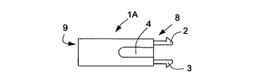
参照符号1Aで示される(図1A乃至図1D及び図2)第1の実施例による固定装置1は、バックパネル10(本実施例での参照符号10A)を有する電気機器(例えばDSLモデム等)の内部の電気コネクタC2に、PSUコネクタC1を維持するようにされている。参照符号C1Aで示されるPSUコネクタC1は接触ピンを有し、参照符号C2Aで示される内部コネクタは該ピンを受け、内部に維持するようにされる。2つのコネクタC1A及びC2Aは、当該実施例で参照符号11Aで示され矩形を有するパネル10Aのウィンドウ11を通って結合されるよう設けられる。
The fixing device 1 according to the first embodiment indicated by
固定装置1Aは、プラスチック等の柔軟性のある材料で製造される。当該装置は、動作中にパネル10Aに向かって方向づけられる前端部8に配置された2つのクリップ2及び3を有する。クリップ2及び3は、固定装置1Aの前端部8を有利には強く締め付けることにより、互いに対して強く締め付けられるよう設けられる。
The fixing
かかる変形によって、ウィンドウ11Aの近くにおいて、パネル10Aの内部部分に押し付けることによってパネル10Aへの固定装置1Aの締着を維持するよう、パネル10Aのウィンドウ11Aを通して、クリップ2及び3を挿入することが可能となる。また、該変形によって、固定装置1Aがパネル10A内に締着されている場合に、固定装置1Aを解放するよう、クリップ2及び3を互いに対して強く締め付けることが可能である。
With such a deformation, the
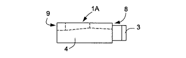
固定装置1Aは、更に、下部の窪み部4と、この窪み部4に繋がる外方開口部5とを設けられ、窪み部4及び外方開口部5は、固定装置1Aの前端部8から後端部9へ、固定装置1Aの長さにおいてそれを通って延びる。窪み部4及び外方開口部5は、前端部8から後端部9へ、横方向に縮小する幅と縮小する高さ(一定の減少ではない)とを有する。
The fixing
窪み部4は、PSUコネクタC1Aを受けることができ、PSUコネクタC1Aは、外方開口部5を通って前端部8から後端部9へ窪み部4内部をスライドすることにより、固定装置1A内に位置づけられうる。このようにして、PSUコネクタC1Aは、固定装置1Aにおいて維持されてもよく、続いて、外方開口部5(前端部8の側部)及びパネル10Aの開口部11Aを通って、内部コネクタC2Aに接続されてもよい。
The
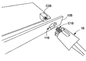
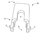
第2の実施例(図3乃至8)において、参照符号1Bで示される固定装置1の窪み部4及び外方開口部5は、固定装置1Bの長手方向軸と平行する段付きエッジ部E1及びE2により横方向に範囲を区切られている点で、第1の実施例とは基本的に異なる。また、参照符号10Bで示されるバックパネル10は、(矩形の代わりに)十字型のウィンドウ11Bを有しており、参照符号1Bで示される固定装置1の前方は、そこを通って位置づけられうる。
In the second embodiment (FIGS. 3 to 8), the
第3の実施例(図9)において、第2の実施例との主な相違は、参照符号C1C及びC2Cで示されるコネクタC1及びC2の性質に依存する。実際には、電気コネクタC1C及びC2Cは夫々、プラグUSBコネクタ(「Universal Serial Bus」)及び対応する内部USBコネクタに在り、参照符号10Cで示されるバックパネル10の、参照符号11Cで示されるウィンドウ11を通って接続されるようにされる。
In the third embodiment (FIG. 9), the main difference from the second embodiment depends on the nature of the connectors C1 and C2 indicated by reference numerals C1C and C2C. In practice, the electrical connectors C1C and C2C are located on the plug USB connector ("Universal Serial Bus") and the corresponding internal USB connector, respectively, and on the back panel 10 indicated by
1A 固定装置
2 クリップ
3 クリップ
4 窪み部
5 外方開口部
8 前端部
9 後端部
10A バックパネル
11A ウィンドウ
C1A PSUコネクタ
C2A 内部コネクタ
DESCRIPTION OF
Claims (1)
前記第2の電気コネクタ(C2)は、当該固定装置(1)と第2の電気コネクタ(C2)との間に置かれたパネル(10)の後方に配置され、該パネル(10)は、少なくとも1つのウィンドウ(11)を有し、前記第1(C1)及び前記第2のコネクタ(C2)を前記ウィンドウ(11)を通して接続させ、
当該固定装置(1)は、
当該固定装置(1)の前端部(8)に配置された少なくとも2つのクリップ(2,3)と、
当該固定装置(1)の内部の少なくとも1つの窪み部(4)と、
該窪み部(4)に繋がる少なくとも1つの外方開口部(5)と、
を有し、
前記前端部(8)は、前記パネル(10)に向かって方向付けられ、
前記クリップ(2,3)は、互いに向かって締め付けられて前記ウィンドウ(11)を通って前記パネル(10)に挿入され、続いて緩められて前記ウィンドウ(11)に隣接する前記パネル(10)の部分に押し付けられ、当該固定装置(1)の前記パネル(10)への締着を維持し、また、互いに向かって再び締め付けられ前記パネル(10)から取り外されて当該固定装置(1)を解放するよう、設けられ、
前記窪み部(4)は、当該固定装置の前記前端部(8)から始まり、該前端部(8)とは反対側にある前記固定装置の後端部(9)に向かって延び、
前記窪み部(4)は、前記外方開口部(5)を通って前記第1の電気コネクタ(C1)を受けるようにされ、前記第1のコネクタ(C1)は、当該固定装置(1)内に維持されたままであり、また、当該固定装置(1)の前記前端部(8)の前記外方開口部(5)を通り前記第2の電気コネクタ(C2)に接続され得、
前記窪み部(4)は、多種の型及び寸法を有する前記第1のコネクタ(C1)を受容するよう、当該固定装置の前記前端部(8)から前記後端部(9)への方向において横方向に減少する寸法を有し、ユーザは、当該固定装置の前記前端部(8)から前記後端部(9)への方向において、前記窪み部(4)内部で前記第1のコネクタ(C1)をスライドさせることによって当該固定装置(1)に前記第1のコネクタ(C1)を位置づけることができ、また、前記固定装置の前記後端部(9)から前記前端部(8)への方向において、前記窪み部(4)内部で前記第1のコネクタ(C1)をスライドさせることによって当該固定装置(1)から前記第1のコネクタ(C1)を取り外すことができる、
ことを特徴とする固定装置(1)。
What fixing device (1) der to maintain contact with the first second electrical connector of the electrical connector (C1) (C2),
Said second electrical connector (C2) is arranged behind the placed panels (10) between the fixing device (1) and the second electrical connector (C2), said panel (10), Having at least one window (11), connecting the first (C1) and the second connector (C2) through the window (11);
The fixing device (1)
At least two clips (2, 3) arranged at the front end (8) of the fixing device (1);
At least one recess (4) inside the fixing device (1);
At least one outer opening leading to the recess (4) and (5),
Have
The front end (8) is directed toward bought to the panel (10),
The clip (2, 3) is inserted into the panel (10) through the window clamped towards each other (11), followed by loosened by said panel adjacent said window (11) (10) of pressed against the part, maintaining the fastening of the panel (10) of the anchoring device (1), also the fixing device is removed again from the tightened the panel towards one another (10) to (1) to release, provided we are,
The recess portion (4), the start from the front end (8) of the fixing device, extends toward the rear end portion of the fixing device on the opposite side (9) and the front end (8),
The recess portion (4), the outer being adapted opening through (5) receiving said first electrical connector (C1), said first connector (C1) is, the fixing device (1 ) remains maintained in, also, the said outer opening (5) connected to the street the second electrical connector (C2) obtained in the front end (8) of the anchoring device (1),
The recess (4) is in the direction from the front end (8) to the rear end (9) of the fixing device so as to receive the first connector (C1) having various types and sizes . has dimensions which decreases laterally user Oite the front end of the fixing device (8) in the direction of the rear section (9), said recess (4) inside said first connector (C1) can be positioned with the first connector (C1) to the fixing device I by the sliding the (1), also the front end from the rear end portion of the locking device (9) Oite direction to (8), the recess portion (4) the said inside first connector (C1) from the fixing device I by that sliding (1) a first connector (C1) Can be removed ,
A fixing device (1) characterized in that.
Applications Claiming Priority (2)
| Application Number | Priority Date | Filing Date | Title |
|---|---|---|---|
| EP04447063.1 | 2004-03-12 | ||
| EP04447063A EP1575134A1 (en) | 2004-03-12 | 2004-03-12 | Securing device for electrical connectors and application thereof |
Publications (3)
| Publication Number | Publication Date |
|---|---|
| JP2005259698A JP2005259698A (en) | 2005-09-22 |
| JP2005259698A5 JP2005259698A5 (en) | 2008-04-17 |
| JP4711705B2 true JP4711705B2 (en) | 2011-06-29 |
Family
ID=34814480
Family Applications (1)
| Application Number | Title | Priority Date | Filing Date |
|---|---|---|---|
| JP2005064215A Active JP4711705B2 (en) | 2004-03-12 | 2005-03-08 | Electric connector fixing device and application method thereof |
Country Status (8)
| Country | Link |
|---|---|
| US (1) | US7077698B2 (en) |
| EP (1) | EP1575134A1 (en) |
| JP (1) | JP4711705B2 (en) |
| KR (1) | KR101123224B1 (en) |
| CN (1) | CN100511864C (en) |
| BR (1) | BRPI0501098B1 (en) |
| DE (1) | DE602005004317T2 (en) |
| MX (1) | MXPA05002741A (en) |
Cited By (1)
| Publication number | Priority date | Publication date | Assignee | Title |
|---|---|---|---|---|
| CN102882063A (en) * | 2011-07-15 | 2013-01-16 | 泰科电子日本合同会社 | Electrical connector |
Families Citing this family (22)
| Publication number | Priority date | Publication date | Assignee | Title |
|---|---|---|---|---|
| GB2422729B (en) * | 2005-11-16 | 2008-10-22 | High Performance Entpr Plc | Personal computer power supply unit |
| US7749015B2 (en) * | 2005-11-25 | 2010-07-06 | Mitsubishi Electric Corporation | Connector holding clamp and connector retaining structure |
| JP2007287367A (en) * | 2006-04-13 | 2007-11-01 | Oki Electric Ind Co Ltd | Power plug falling preventing structure and cap for preventing falling of power plug |
| US7270560B1 (en) * | 2006-05-03 | 2007-09-18 | Rockwell Automation Technologies, Inc. | USB connector locking device with lock prongs or movable lock ring |
| KR100830696B1 (en) * | 2006-07-24 | 2008-05-20 | 한국단자공업 주식회사 | Connector clip |
| JP2011517274A (en) | 2008-04-09 | 2011-05-26 | スリーエム イノベイティブ プロパティズ カンパニー | Telecommunications cable entry device |
| JP2010114006A (en) * | 2008-11-07 | 2010-05-20 | Sharp Corp | Falling-off prevention tool and electronic device |
| US7934949B2 (en) * | 2009-07-30 | 2011-05-03 | Cisco Technology, Inc. | Cable connector apparatus |
| US8469734B2 (en) | 2010-04-20 | 2013-06-25 | Liang Light Chen | Retainer system for electric cable couplers |
| US8485839B2 (en) * | 2010-05-21 | 2013-07-16 | Seagate Technology Llc | Modular interface communications with a storage cartridge |
| JP2011249266A (en) * | 2010-05-31 | 2011-12-08 | Fujitsu Telecom Networks Ltd | Power cable fall-off preventing structure |
| CN102299447A (en) * | 2010-06-23 | 2011-12-28 | 鸿富锦精密工业(深圳)有限公司 | Flat cable limiting device and display with same |
| JP5555377B2 (en) * | 2010-07-01 | 2014-07-23 | ボルボ コンストラクション イクイップメント アーベー | Clip for construction machinery with multi-directional latch |
| TW201302000A (en) * | 2011-06-17 | 2013-01-01 | Hon Hai Prec Ind Co Ltd | Electronic device |
| CN102842797A (en) * | 2011-06-20 | 2012-12-26 | 鸿富锦精密工业(深圳)有限公司 | Electronic device |
| JP6054197B2 (en) * | 2013-02-13 | 2016-12-27 | セイコーソリューションズ株式会社 | Connector module reinforcement device |
| CN104767075A (en) * | 2013-10-14 | 2015-07-08 | 豪利士公开有限公司 | Positive lock connector for small power couplers |
| JP6570431B2 (en) * | 2015-11-13 | 2019-09-04 | 日本航空電子工業株式会社 | Connector and connector assembly |
| WO2017086259A1 (en) * | 2015-11-20 | 2017-05-26 | 北川工業株式会社 | Connector fixture |
| US10665998B1 (en) * | 2018-12-18 | 2020-05-26 | Hampton Electric, Llc | Cable through panel feedthrough connector with release buttons |
| CN113078499B (en) * | 2021-04-10 | 2022-10-21 | 深圳耐特通信设备有限公司 | Modular USB charging socket |
| KR20230027413A (en) | 2021-08-19 | 2023-02-28 | 한국단자공업 주식회사 | Connector and connector assembly |
Citations (2)
| Publication number | Priority date | Publication date | Assignee | Title |
|---|---|---|---|---|
| JPS5834372U (en) * | 1981-08-31 | 1983-03-05 | 松下電工株式会社 | Outlet plug locking device |
| JPH0236188U (en) * | 1988-08-30 | 1990-03-08 |
Family Cites Families (7)
| Publication number | Priority date | Publication date | Assignee | Title |
|---|---|---|---|---|
| US3337836A (en) * | 1963-10-03 | 1967-08-22 | Kent Mfg Corp | Plug and receptacle connector |
| US3394338A (en) * | 1967-05-24 | 1968-07-23 | Foxboro Co | Explosion-proof electrical connector |
| US3523269A (en) * | 1968-03-08 | 1970-08-04 | Essex International Inc | Panel locking terminal connector block |
| US5279507A (en) * | 1991-09-26 | 1994-01-18 | Yazaki Corporation | Connector for use in vehicles |
| US5525074A (en) * | 1993-07-12 | 1996-06-11 | Yazaki Corporation | Panel mounted connector |
| US5895289A (en) * | 1997-08-27 | 1999-04-20 | The Whitaker Corporation | Retainer to mount a connector in a panel |
| JP2000286022A (en) * | 1999-03-31 | 2000-10-13 | Sharp Corp | Terminal connector for electronic and electronic |
-
2004
- 2004-03-12 EP EP04447063A patent/EP1575134A1/en not_active Withdrawn
-
2005
- 2005-02-25 DE DE602005004317T patent/DE602005004317T2/en active Active
- 2005-03-08 JP JP2005064215A patent/JP4711705B2/en active Active
- 2005-03-08 US US11/074,954 patent/US7077698B2/en active Active
- 2005-03-09 KR KR1020050019511A patent/KR101123224B1/en active IP Right Grant
- 2005-03-11 BR BRPI0501098-5A patent/BRPI0501098B1/en active IP Right Grant
- 2005-03-11 CN CNB2005100547599A patent/CN100511864C/en active Active
- 2005-03-11 MX MXPA05002741A patent/MXPA05002741A/en active IP Right Grant
Patent Citations (2)
| Publication number | Priority date | Publication date | Assignee | Title |
|---|---|---|---|---|
| JPS5834372U (en) * | 1981-08-31 | 1983-03-05 | 松下電工株式会社 | Outlet plug locking device |
| JPH0236188U (en) * | 1988-08-30 | 1990-03-08 |
Cited By (2)
| Publication number | Priority date | Publication date | Assignee | Title |
|---|---|---|---|---|
| CN102882063A (en) * | 2011-07-15 | 2013-01-16 | 泰科电子日本合同会社 | Electrical connector |
| CN102882063B (en) * | 2011-07-15 | 2016-03-16 | 泰科电子日本合同会社 | Electric connector |
Also Published As
| Publication number | Publication date |
|---|---|
| US7077698B2 (en) | 2006-07-18 |
| BRPI0501098B1 (en) | 2017-12-19 |
| US20050202719A1 (en) | 2005-09-15 |
| CN1667885A (en) | 2005-09-14 |
| BRPI0501098A (en) | 2005-11-01 |
| DE602005004317T2 (en) | 2009-01-08 |
| DE602005004317D1 (en) | 2008-03-06 |
| KR101123224B1 (en) | 2012-03-20 |
| MXPA05002741A (en) | 2005-09-14 |
| KR20060043575A (en) | 2006-05-15 |
| JP2005259698A (en) | 2005-09-22 |
| CN100511864C (en) | 2009-07-08 |
| EP1575134A1 (en) | 2005-09-14 |
Similar Documents
| Publication | Publication Date | Title |
|---|---|---|
| JP4711705B2 (en) | Electric connector fixing device and application method thereof | |
| JP2006029566A (en) | Band clamp | |
| JP2007159259A (en) | Wiring holding unit | |
| US6652289B2 (en) | Vehicle door connector structure | |
| JP2004355987A (en) | Waterproof modular connector | |
| JPH1126097A (en) | Socket to be installed in panel | |
| TWI645630B (en) | Connectors for connecting cables | |
| JP2011249266A (en) | Power cable fall-off preventing structure | |
| US10461474B2 (en) | Technology for maintaining secure connections of electronic cabling | |
| WO2022142701A1 (en) | Printed circuit board assembly fixing assembly for safety airbag of steering wheel | |
| JP2007220540A (en) | Terminal block and lighting device | |
| JP5579486B2 (en) | Screw tightening method for one electric wire using one combination terminal | |
| US6935880B1 (en) | Coupling fixture for inserting power supply input sockets | |
| TWM582539U (en) | Board-to-board fixing structure for elliptical hole | |
| JP5092989B2 (en) | CF card retaining mechanism for portable devices | |
| CN216644147U (en) | Waterproof plug combined structure | |
| KR100833698B1 (en) | Assembling structure of grommet for vehicle | |
| KR200169307Y1 (en) | The device fixing harness, cable, pipe, or hose | |
| JP2010145464A (en) | Guide structure of optical cable | |
| KR200385731Y1 (en) | a pipe joint structure | |
| JPS5836185Y2 (en) | cable holder | |
| JP2006049199A (en) | Wire harness | |
| EP1575135B1 (en) | Securing device for electrical connectors and application thereof | |
| CN204801683U (en) | Installation buckle of pencil, installation device and car of pencil | |
| JPH0711832U (en) | Waterproof cap for attached connector of wire harness |
Legal Events
| Date | Code | Title | Description |
|---|---|---|---|
| A521 | Request for written amendment filed |
Free format text: JAPANESE INTERMEDIATE CODE: A523 Effective date: 20080305 |
|
| A621 | Written request for application examination |
Free format text: JAPANESE INTERMEDIATE CODE: A621 Effective date: 20080305 |
|
| A131 | Notification of reasons for refusal |
Free format text: JAPANESE INTERMEDIATE CODE: A131 Effective date: 20100511 |
|
| A521 | Request for written amendment filed |
Free format text: JAPANESE INTERMEDIATE CODE: A523 Effective date: 20100810 |
|
| TRDD | Decision of grant or rejection written | ||
| A01 | Written decision to grant a patent or to grant a registration (utility model) |
Free format text: JAPANESE INTERMEDIATE CODE: A01 Effective date: 20110222 |
|
| A61 | First payment of annual fees (during grant procedure) |
Free format text: JAPANESE INTERMEDIATE CODE: A61 Effective date: 20110322 |
|
| R150 | Certificate of patent or registration of utility model |
Ref document number: 4711705 Country of ref document: JP Free format text: JAPANESE INTERMEDIATE CODE: R150 |
|
| R250 | Receipt of annual fees |
Free format text: JAPANESE INTERMEDIATE CODE: R250 |
|
| S111 | Request for change of ownership or part of ownership |
Free format text: JAPANESE INTERMEDIATE CODE: R313113 |
|
| S531 | Written request for registration of change of domicile |
Free format text: JAPANESE INTERMEDIATE CODE: R313531 |
|
| R250 | Receipt of annual fees |
Free format text: JAPANESE INTERMEDIATE CODE: R250 |
|
| R371 | Transfer withdrawn |
Free format text: JAPANESE INTERMEDIATE CODE: R371 |
|
| R371 | Transfer withdrawn |
Free format text: JAPANESE INTERMEDIATE CODE: R371 |
|
| S531 | Written request for registration of change of domicile |
Free format text: JAPANESE INTERMEDIATE CODE: R313531 |
|
| R350 | Written notification of registration of transfer |
Free format text: JAPANESE INTERMEDIATE CODE: R350 |
|
| S111 | Request for change of ownership or part of ownership |
Free format text: JAPANESE INTERMEDIATE CODE: R313113 |
|
| R350 | Written notification of registration of transfer |
Free format text: JAPANESE INTERMEDIATE CODE: R350 |
|
| R250 | Receipt of annual fees |
Free format text: JAPANESE INTERMEDIATE CODE: R250 |
|
| R250 | Receipt of annual fees |
Free format text: JAPANESE INTERMEDIATE CODE: R250 |
|
| R250 | Receipt of annual fees |
Free format text: JAPANESE INTERMEDIATE CODE: R250 |
|
| R250 | Receipt of annual fees |
Free format text: JAPANESE INTERMEDIATE CODE: R250 |
|
| R250 | Receipt of annual fees |
Free format text: JAPANESE INTERMEDIATE CODE: R250 |