JP4711627B2 - Multi-lumen catheter - Google Patents
Multi-lumen catheter Download PDFInfo
- Publication number
- JP4711627B2 JP4711627B2 JP2003572618A JP2003572618A JP4711627B2 JP 4711627 B2 JP4711627 B2 JP 4711627B2 JP 2003572618 A JP2003572618 A JP 2003572618A JP 2003572618 A JP2003572618 A JP 2003572618A JP 4711627 B2 JP4711627 B2 JP 4711627B2
- Authority
- JP
- Japan
- Prior art keywords
- lumen
- tube
- sensor
- catheter
- infusion
- Prior art date
- Legal status (The legal status is an assumption and is not a legal conclusion. Google has not performed a legal analysis and makes no representation as to the accuracy of the status listed.)
- Expired - Fee Related
Links
Images


Classifications
-
- A—HUMAN NECESSITIES
- A61—MEDICAL OR VETERINARY SCIENCE; HYGIENE
- A61M—DEVICES FOR INTRODUCING MEDIA INTO, OR ONTO, THE BODY; DEVICES FOR TRANSDUCING BODY MEDIA OR FOR TAKING MEDIA FROM THE BODY; DEVICES FOR PRODUCING OR ENDING SLEEP OR STUPOR
- A61M25/00—Catheters; Hollow probes
- A61M25/0021—Catheters; Hollow probes characterised by the form of the tubing
- A61M25/0023—Catheters; Hollow probes characterised by the form of the tubing by the form of the lumen, e.g. cross-section, variable diameter
- A61M25/0026—Multi-lumen catheters with stationary elements
- A61M25/0032—Multi-lumen catheters with stationary elements characterized by at least one unconventionally shaped lumen, e.g. polygons, ellipsoids, wedges or shapes comprising concave and convex parts
-
- A—HUMAN NECESSITIES
- A61—MEDICAL OR VETERINARY SCIENCE; HYGIENE
- A61B—DIAGNOSIS; SURGERY; IDENTIFICATION
- A61B5/00—Measuring for diagnostic purposes; Identification of persons
- A61B5/145—Measuring characteristics of blood in vivo, e.g. gas concentration, pH value; Measuring characteristics of body fluids or tissues, e.g. interstitial fluid, cerebral tissue
- A61B5/14532—Measuring characteristics of blood in vivo, e.g. gas concentration, pH value; Measuring characteristics of body fluids or tissues, e.g. interstitial fluid, cerebral tissue for measuring glucose, e.g. by tissue impedance measurement
-
- A—HUMAN NECESSITIES
- A61—MEDICAL OR VETERINARY SCIENCE; HYGIENE
- A61B—DIAGNOSIS; SURGERY; IDENTIFICATION
- A61B5/00—Measuring for diagnostic purposes; Identification of persons
- A61B5/41—Detecting, measuring or recording for evaluating the immune or lymphatic systems
- A61B5/414—Evaluating particular organs or parts of the immune or lymphatic systems
- A61B5/415—Evaluating particular organs or parts of the immune or lymphatic systems the glands, e.g. tonsils, adenoids or thymus
-
- A—HUMAN NECESSITIES
- A61—MEDICAL OR VETERINARY SCIENCE; HYGIENE
- A61M—DEVICES FOR INTRODUCING MEDIA INTO, OR ONTO, THE BODY; DEVICES FOR TRANSDUCING BODY MEDIA OR FOR TAKING MEDIA FROM THE BODY; DEVICES FOR PRODUCING OR ENDING SLEEP OR STUPOR
- A61M25/00—Catheters; Hollow probes
- A61M25/0017—Catheters; Hollow probes specially adapted for long-term hygiene care, e.g. urethral or indwelling catheters to prevent infections
-
- A—HUMAN NECESSITIES
- A61—MEDICAL OR VETERINARY SCIENCE; HYGIENE
- A61M—DEVICES FOR INTRODUCING MEDIA INTO, OR ONTO, THE BODY; DEVICES FOR TRANSDUCING BODY MEDIA OR FOR TAKING MEDIA FROM THE BODY; DEVICES FOR PRODUCING OR ENDING SLEEP OR STUPOR
- A61M5/00—Devices for bringing media into the body in a subcutaneous, intra-vascular or intramuscular way; Accessories therefor, e.g. filling or cleaning devices, arm-rests
- A61M5/14—Infusion devices, e.g. infusing by gravity; Blood infusion; Accessories therefor
- A61M5/142—Pressure infusion, e.g. using pumps
- A61M5/14244—Pressure infusion, e.g. using pumps adapted to be carried by the patient, e.g. portable on the body
-
- A—HUMAN NECESSITIES
- A61—MEDICAL OR VETERINARY SCIENCE; HYGIENE
- A61M—DEVICES FOR INTRODUCING MEDIA INTO, OR ONTO, THE BODY; DEVICES FOR TRANSDUCING BODY MEDIA OR FOR TAKING MEDIA FROM THE BODY; DEVICES FOR PRODUCING OR ENDING SLEEP OR STUPOR
- A61M5/00—Devices for bringing media into the body in a subcutaneous, intra-vascular or intramuscular way; Accessories therefor, e.g. filling or cleaning devices, arm-rests
- A61M5/14—Infusion devices, e.g. infusing by gravity; Blood infusion; Accessories therefor
- A61M5/168—Means for controlling media flow to the body or for metering media to the body, e.g. drip meters, counters ; Monitoring media flow to the body
- A61M5/172—Means for controlling media flow to the body or for metering media to the body, e.g. drip meters, counters ; Monitoring media flow to the body electrical or electronic
- A61M5/1723—Means for controlling media flow to the body or for metering media to the body, e.g. drip meters, counters ; Monitoring media flow to the body electrical or electronic using feedback of body parameters, e.g. blood-sugar, pressure
-
- A—HUMAN NECESSITIES
- A61—MEDICAL OR VETERINARY SCIENCE; HYGIENE
- A61B—DIAGNOSIS; SURGERY; IDENTIFICATION
- A61B5/00—Measuring for diagnostic purposes; Identification of persons
- A61B5/02—Detecting, measuring or recording pulse, heart rate, blood pressure or blood flow; Combined pulse/heart-rate/blood pressure determination; Evaluating a cardiovascular condition not otherwise provided for, e.g. using combinations of techniques provided for in this group with electrocardiography or electroauscultation; Heart catheters for measuring blood pressure
- A61B5/026—Measuring blood flow
- A61B5/0275—Measuring blood flow using tracers, e.g. dye dilution
- A61B5/028—Measuring blood flow using tracers, e.g. dye dilution by thermo-dilution
-
- A—HUMAN NECESSITIES
- A61—MEDICAL OR VETERINARY SCIENCE; HYGIENE
- A61B—DIAGNOSIS; SURGERY; IDENTIFICATION
- A61B5/00—Measuring for diagnostic purposes; Identification of persons
- A61B5/145—Measuring characteristics of blood in vivo, e.g. gas concentration, pH value; Measuring characteristics of body fluids or tissues, e.g. interstitial fluid, cerebral tissue
- A61B5/1486—Measuring characteristics of blood in vivo, e.g. gas concentration, pH value; Measuring characteristics of body fluids or tissues, e.g. interstitial fluid, cerebral tissue using enzyme electrodes, e.g. with immobilised oxidase
-
- A—HUMAN NECESSITIES
- A61—MEDICAL OR VETERINARY SCIENCE; HYGIENE
- A61M—DEVICES FOR INTRODUCING MEDIA INTO, OR ONTO, THE BODY; DEVICES FOR TRANSDUCING BODY MEDIA OR FOR TAKING MEDIA FROM THE BODY; DEVICES FOR PRODUCING OR ENDING SLEEP OR STUPOR
- A61M25/00—Catheters; Hollow probes
- A61M2025/0001—Catheters; Hollow probes for pressure measurement
- A61M2025/0003—Catheters; Hollow probes for pressure measurement having an additional lumen transmitting fluid pressure to the outside for measurement
-
- A—HUMAN NECESSITIES
- A61—MEDICAL OR VETERINARY SCIENCE; HYGIENE
- A61M—DEVICES FOR INTRODUCING MEDIA INTO, OR ONTO, THE BODY; DEVICES FOR TRANSDUCING BODY MEDIA OR FOR TAKING MEDIA FROM THE BODY; DEVICES FOR PRODUCING OR ENDING SLEEP OR STUPOR
- A61M25/00—Catheters; Hollow probes
- A61M25/0043—Catheters; Hollow probes characterised by structural features
- A61M25/0045—Catheters; Hollow probes characterised by structural features multi-layered, e.g. coated
- A61M2025/0046—Coatings for improving slidability
-
- A—HUMAN NECESSITIES
- A61—MEDICAL OR VETERINARY SCIENCE; HYGIENE
- A61M—DEVICES FOR INTRODUCING MEDIA INTO, OR ONTO, THE BODY; DEVICES FOR TRANSDUCING BODY MEDIA OR FOR TAKING MEDIA FROM THE BODY; DEVICES FOR PRODUCING OR ENDING SLEEP OR STUPOR
- A61M2230/00—Measuring parameters of the user
- A61M2230/20—Blood composition characteristics
- A61M2230/201—Glucose concentration
-
- A—HUMAN NECESSITIES
- A61—MEDICAL OR VETERINARY SCIENCE; HYGIENE
- A61M—DEVICES FOR INTRODUCING MEDIA INTO, OR ONTO, THE BODY; DEVICES FOR TRANSDUCING BODY MEDIA OR FOR TAKING MEDIA FROM THE BODY; DEVICES FOR PRODUCING OR ENDING SLEEP OR STUPOR
- A61M25/00—Catheters; Hollow probes
- A61M25/0021—Catheters; Hollow probes characterised by the form of the tubing
- A61M25/0023—Catheters; Hollow probes characterised by the form of the tubing by the form of the lumen, e.g. cross-section, variable diameter
-
- Y—GENERAL TAGGING OF NEW TECHNOLOGICAL DEVELOPMENTS; GENERAL TAGGING OF CROSS-SECTIONAL TECHNOLOGIES SPANNING OVER SEVERAL SECTIONS OF THE IPC; TECHNICAL SUBJECTS COVERED BY FORMER USPC CROSS-REFERENCE ART COLLECTIONS [XRACs] AND DIGESTS
- Y10—TECHNICAL SUBJECTS COVERED BY FORMER USPC
- Y10T—TECHNICAL SUBJECTS COVERED BY FORMER US CLASSIFICATION
- Y10T29/00—Metal working
- Y10T29/49—Method of mechanical manufacture
- Y10T29/49826—Assembling or joining
Description
本発明の実施形態は、ここに引用により援用するとともに、優先権主張の基礎となる2002年9月27日付、米国仮出願第60/414,248号「多管腔カテーテル」と、さらにこれも引用により援用する2002年3月1日付、米国仮出願第60/390,940号「中心ライン中の被分析物濃度の監視システムおよびその方法」に関する。 Embodiments of the present invention are hereby incorporated by reference and are based on US Patent Application No. 60 / 414,248 “Multilumen Catheter” dated September 27, 2002, which is the basis for priority claims, and also by reference. US Provisional Application No. 60 / 390,940 entitled “System and Method for Monitoring Analyte Concentration in Center Line” dated March 1, 2002.
本発明は、生物医学の分野で使用されるカテーテルならびに被分析物および治療センサの分野に関し、特に、複数の管腔を有するカテーテルおよびこれを製造、使用するプロセス、ならびに救命医療の現場で使用する被分析物および治療センサに関する。 The present invention relates to the field of catheters used in the field of biomedicine and analytes and therapeutic sensors, and more particularly to catheters having multiple lumens and processes for making and using the same, and in the field of life-saving medicine. The invention relates to analytes and therapeutic sensors.
救命医療または集中治療の環境でのバイタルサイン(生命徴候)や他の生物医学または生理学的パラメータの正確かつ適時の監視(モニタリング)は、患者とその患者に治療を施す医療従事者にとって成功と不幸の差を意味することがしばしばある。このような患者にとっては、クオリティ・オブ・ライフ、すなわち生活の質、ともすると生命そのものがこの監視次第となる場合もある。重大である一方で、生理学的パラメータの監視の中には、従来、遅く、やっかいなタイプのものがあった。たとえば、集中治療の環境にある患者、特に糖尿病患者にとっては、ブドウ糖の監視は重大である。患者の体内でのブドウ糖量が適切なレベルに維持されなければ、重大または生命に関わる損傷を被るおそれがある。患者の体内でブドウ糖が蓄積されすぎると、患者は高血糖となり、良くても、息切れ、吐き気、嘔吐、最悪の場合には昏睡状態、さらに死に至る可能性がある。患者の体内でのブドウ糖量が少なすぎると低血糖となり、良くても、めまい、発汗、頭痛、最悪の場合には意識不明、さらに死に至る可能性がある。救命医療または集中治療の環境ではブドウ糖の監視は、通常、手作業で行ってきた。たとえば、施設の中には、糖尿病患者が救命または集中治療の環境にある場合、医療従事者が患者から血液サンプルを採り、できれば現場にある研究室に送ってブドウ糖分析を行い、その結果に基づいて患者が治療され、患者が高血糖であるか低血糖であるかによって、それぞれインシュリンまたはブドウ糖注入を行う所もある。このプロセス、すなわち患者から血液サンプルを採ってその血液を研究室に送って分析し、分析結果を患者の治療を行う者に返し、分析結果を見て、適切な治療を勧め、治療を施すというのは、面倒であるし、人為的ミスが生じがちである。患者のためには、患者を救命または集中治療病棟に送ってから、薬剤を注入して血糖レベルが安定するまでの時間が最短であるのが理想的である。しかし、研究室での診断、そして手作業での分析という本質に鑑みると、患者を送ってからブドウ糖分析、そして最終的には治療までの時間のずれが、望ましいレベルよりも長いことがある。さらに、患者に施す治療のため、患者の体内に1以上のカテーテルが挿入され得る。たとえば、患者の治療に血液とインシュリン、血液と薬剤、血液とブドウ糖等の注入が必要な場合、従来、治療従事者は患者の体内に2つのカテーテルを別々に入れ、各カテーテルを適切な注入送達システムに接続していた。さらに、使用する各カテーテルについて、患者にとっては肉体的に非常に不快となり得るカテーテルトンネリング処置を行わなくてはならない。さらに、患者の体から出る各カテーテルについて、カテーテルが乱されたり、誤って抜かれたり、上昇を妨げられたりする危険がある。さらに、カテーテルを複数使用すると感染のリスクが高くなる。長年、身体的特徴は体液のサンプルを採取することによって測定してきた。たとえば、糖尿病患者は血糖測定器で血糖レベルをテストすることが多い。従来の血糖値の測定では、血糖測定器に使う少量の血液サンプルを採るのにランセットで指を刺すという、痛みを伴う方法を使用してきた。しかし、救命救急の状況においては、これらの不連続な血糖値の読みとりは血液性状を厳密に監視するには効率が悪い。というのも、救命救急の状況下で必要な、ほぼ連続したデータを提供するべく、毎分読みとりを行う必要があるからである。体内に数週、数ヶ月といった長期にわたって留めておくことができる、長期埋込み型センサも提案されてきた。これらの長期埋込み型センサは、心臓付近の大動脈の1つに埋め込まれるため、ある程度の期間にわたって信頼できるデータを送る場合や、血液性状における急な変化を検出する場合には、特によく適合している。しかし、これらのセンサの埋め込みは別の処置を必要とするため、救命救急の患者には実現不可能なことが多い。さらに、埋込み型センサ(ブドウ糖センサ等)は長期の病気療養を要する糖尿病患者には理にかなっているかもしれないが、糖尿病でない患者は集中治療室を出ると長期の埋込み型センサを必要としないかもしれない。 Accurate and timely monitoring of vital signs and other biomedical or physiological parameters in a lifesaving or intensive care setting is a success and misfortune for the patient and the healthcare professional who is treating the patient. Often it means the difference. For such patients, quality of life, that is, quality of life, or even life itself may depend on this monitoring. While critical, some of the physiological parameter monitoring has traditionally been slow and troublesome. For example, glucose monitoring is critical for patients in an intensive care environment, particularly diabetics. If the glucose level in the patient's body is not maintained at an appropriate level, serious or life-threatening damage can occur. If too much glucose is accumulated in the patient's body, the patient may become hyperglycemic and, at best, lead to shortness of breath, nausea, vomiting, in the worst case coma and even death. Too little glucose in the patient's body can lead to hypoglycemia, which at best can lead to dizziness, sweating, headaches, worst case unconsciousness, and even death. In lifesaving or intensive care settings, glucose monitoring has typically been done manually. For example, in some facilities, if a diabetic patient is in a lifesaving or intensive care setting, a health care worker will take a blood sample from the patient and, if possible, send it to a laboratory in the field for glucose analysis and based on the results. Some patients are treated with insulin or glucose infusion depending on whether the patient is hyperglycemic or hypoglycemic, respectively. In this process, taking a blood sample from a patient, sending the blood to the laboratory for analysis, returning the analysis result to the patient's treatment person, looking at the analysis result, recommending appropriate treatment and giving treatment Is troublesome and prone to human error. Ideally, the patient should have the shortest time between sending the patient to a lifesaving or intensive care unit and injecting the drug to stabilize blood glucose levels. However, in view of the essence of laboratory diagnosis and manual analysis, the time lag between sending a patient and glucose analysis and ultimately treatment may be longer than desired. In addition, one or more catheters may be inserted into the patient's body for treatment applied to the patient. For example, if blood and insulin, blood and drugs, blood and glucose, etc. are required for treatment of a patient, conventionally, a medical practitioner places two catheters in the patient's body separately, and delivers each catheter appropriately. Connected to the system. In addition, for each catheter used, a catheter tunneling procedure must be performed which can be very uncomfortable for the patient. In addition, for each catheter exiting the patient's body, there is a risk that the catheter will be disturbed, accidentally pulled out, or prevented from rising. In addition, the use of multiple catheters increases the risk of infection. For many years, physical characteristics have been measured by taking samples of body fluids. For example, diabetics often test blood glucose levels with a blood glucose meter. Conventional blood glucose measurement has used a painful method of puncturing a finger with a lancet to take a small blood sample for use in a blood glucose meter. However, in the critical care situation, these discontinuous blood glucose readings are inefficient for closely monitoring blood properties. This is because it is necessary to read every minute in order to provide the nearly continuous data that is necessary in lifesaving situations. Long-term implantable sensors have also been proposed that can remain in the body for a long period of weeks or months. Since these long-term implantable sensors are implanted in one of the aorta near the heart, they are particularly well suited for sending reliable data over a period of time or detecting sudden changes in blood properties. Yes. However, the implantation of these sensors often requires a different procedure, which is often not feasible for critical care patients. In addition, implantable sensors (such as glucose sensors) may make sense for diabetics who need long-term illness treatment, but non-diabetic patients do not need long-term implantable sensors when leaving the intensive care unit It may be.
従って、1以上の注入物を患者に送達できる複数の管腔を有するカテーテルが必要とされている。さらに、バイタルサインや他の生物医学的パラメータを監視するように患者の体内の適切な位置に配置できる感知要素のための1つ以上の管腔を有するカテーテルも必要とされている。さらに、患者への注入物の制御および送達を監視するための、生理学的バイタル(生命に関わる)パラメータの自動分析のための信号を与えることのできるカテーテルも必要とされている。本発明の実施形態は患者に1以上の注入物を送達できる1つまたは複数の管腔を有するカテーテルに関する。本発明の実施形態は、バイタルサインや他の生物医学的パラメータを監視するように患者の体内の適切な位置に配置できる感知要素のための1つ以上の管腔を有するカテーテルを含む。本発明の実施形態は、患者への注入物の制御および送達を監視するための生理学的バイタルパラメータの自動分析のための信号を与えることのできるカテーテルを含む。本発明の実施形態は、実用のため上記の制限を除去する、集中治療室内の患者の血液性状を検出するための改良されたシステムにも関する。本発明の一実施形態による多管腔カテーテルは、それぞれ第1端と第2端とを有し、センサ管腔を含む複数の管腔が内部に配置される第1のチューブと、複数の第2のチューブと、前記第1のチューブの一端側と複数の前記第2のチューブの一端側とが取り付けられ、前記第1のチューブに配置される前記複数の管腔の各第1端と前記複数の第2のチューブの内の各前記第2のチューブの各一端との間の接続を維持する接合要素と、先端側にセンサ要素を含み、前記センサ管腔に接続されている前記第2のチューブを通して前記第1のチューブに配置される前記センサ管腔の第1端から第2端に向かって延びるセンサリードと、を含む多管腔カテーテルであって、前記センサ管腔の一部の断面は前記センサリードの外径よりも小さい第1の長さを含み、前記センサ管腔は前記第1の長さの方向に前記センサリードを圧縮し、前記センサ要素は前記第1のチューブの他端において前記第1のチューブから出ることができ、前記センサリードの前記先端は前記第1のチューブの前記他端を越えて延びると共に前記各管腔の第2端を越えて延びることができること、を特徴とする。本発明の一実施形態による多管腔カテーテルにおいて、前記センサ管腔の断面は楕円形であり、その短径はセンサリードの外径よりも小さいこと、としても好適であるし、前記センサ管腔以外の前記各管腔は前記センサ管腔の周囲に配置され、各他の管腔は断面形状の一部に楕円形のセンサ管腔の輪郭の少なくとも一部に沿った曲線を含む断面形状であることとしても好適であるし、前記第1のチューブの外形の断面は略円形であって、前記センサ管腔以外の前記各管腔は、前記センサ管腔側の管腔内面に略楕円形の前記センサ管腔の輪郭に沿った曲線と前記センサ管腔に向かう第1の角とを含み、前記第1のチューブの外面側の管腔内面に略円形の前記第1のチューブの外形に沿った曲線と前記第1のチューブの外面側に向かう第2の角と、を含む断面形状であることとしても好適である。また、本発明の一実施形態による多管腔カテーテルにおいて、前記複数の第2のチューブに装着するための注入部材をさらに含むこととしても好適であるし、前記複数の管腔が前記第1のチューブと共に押し出し成形されることとしても好適であるし、前記第1のチューブ上の潤滑性コーティングをさらに含むこととしても好適であるし、前記潤滑性コーティングがシロキサンであることとしても好適であるし、前記複数の第2のチューブが、第1の注入物チューブ、第2の注入物チューブ、およびセンサチューブを含むこととしても好適であるし、前記第1のチューブに配置される前記複数の管腔が第1の注入物管腔、第2の注入物管腔を含むこととしても好適であるし、前記第1の注入物チューブが前記第1の注入物管腔へと延び、前記第2の注入物チューブが前記第2の注入物管腔へと延び、前記センサチューブが前記センサ管腔へと延びることとしても好適であるし、前記第1の注入物管腔および前記第2の注入物管腔が、前記第1のチューブの長さに沿った同じ距離において前記第1のチューブから出ることとしても好適であるし、前記第1の注入物管腔および前記第2の注入物管腔が、前記第1のチューブの長さに沿った異なる距離において前記第1のチューブから出ることとしても好適であるし、前記センサ要素が複数の管腔の各第2端を数インチ越えるようにセンサリードが延びることとしても好適であるし、前記センサ要素が複数の管腔の各第2端を数インチ越えるようにセンサリードが延びることとしても好適であるし、前記センサ要素が被分析物センサであることとしても好適であるし、前記センサ要素がグルコース分析センサであることとしても好適であるし、前記センサ要素が前記第1のチューブを数インチ越えるようにセンサリードが延びることとしても好適であるし、前記第1の注入物チューブおよび前記第2の注入物チューブに接続される注入部材をさらに含むこととしても好適であるし、前記注入部材が注射部位を含むこととしても好適であるし、前記多管腔カテーテルがスワン−ガンツカテーテルであることとしても好適であるし、前記多管腔カテーテルが末梢挿入型中心カテーテル(PICC)であることとしても好適であるし、前記複数の管腔の1つがガイドワイヤの経路となるような形状であることとしても好適である。本発明の他の特徴および利点は、本発明の実施形態の種々の特徴を例示する添付の図面と合わせて、以下の詳細な説明より明らかになるであろう。
Accordingly, there is a need for a catheter having multiple lumens that can deliver one or more infusions to a patient. There is a further need for a catheter having one or more lumens for a sensing element that can be placed at an appropriate location in a patient's body to monitor vital signs and other biomedical parameters. There is a further need for a catheter that can provide a signal for automatic analysis of physiological vital parameters to monitor the control and delivery of the infusion to the patient. Embodiments of the invention relate to a catheter having one or more lumens that can deliver one or more infusions to a patient. Embodiments of the present invention include a catheter having one or more lumens for sensing elements that can be placed at appropriate locations within a patient's body to monitor vital signs and other biomedical parameters. Embodiments of the present invention include a catheter that can provide a signal for automatic analysis of physiological vital parameters to monitor infusion control and delivery to a patient. Embodiments of the present invention also relate to an improved system for detecting blood characteristics of a patient in an intensive care unit that eliminates the above limitations for practical use. A multi-lumen catheter according to an embodiment of the present invention includes a first tube having a first end and a second end, each having a plurality of lumens including a sensor lumen, and a plurality of first tubes. Two tubes, one end side of the first tube and one end side of the plurality of second tubes are attached, and each first end of the plurality of lumens disposed in the first tube and the first tube A joining element that maintains a connection between each one end of each of the second tubes of the plurality of second tubes, a sensor element on the distal end side, and the second connected to the sensor lumen A multi-lumen catheter comprising a sensor lead extending from a first end to a second end of the sensor lumen disposed in the first tube through a tube of the sensor lumen, wherein a portion of the sensor lumen The cross section has a first length smaller than the outer diameter of the sensor lead. The sensor lumen compresses the sensor lead in the first length direction, and the sensor element can exit the first tube at the other end of the first tube; The tip of the lead may extend beyond the other end of the first tube and extend beyond the second end of each lumen. In the multi-lumen catheter according to an embodiment of the present invention, the cross section of the sensor lumen is elliptical, and the short diameter is preferably smaller than the outer diameter of the sensor lead. Each of the other lumens is disposed around the sensor lumen, and each other lumen has a cross-sectional shape that includes a curve along at least a portion of an elliptical sensor lumen contour in a portion of the cross-sectional shape. It is also preferable that the cross section of the outer shape of the first tube is substantially circular, and each lumen other than the sensor lumen is substantially elliptical on the inner surface of the lumen on the sensor lumen side. A contour along the contour of the sensor lumen and a first angle toward the sensor lumen, the outer shape of the first tube being substantially circular on the inner surface of the lumen on the outer surface side of the first tube a second corner along curve and toward the outer surface side of the first tube It is also suitable as it is a cross-sectional shape including a. The multi-lumen catheter according to an embodiment of the present invention may further include an injection member for mounting on the plurality of second tubes, and the plurality of lumens may be the first lumen. It may be suitable to be extruded with a tube, may further include a lubricious coating on the first tube, and may be suitable as the lubricious coating is siloxane. The plurality of second tubes may include a first injection tube, a second injection tube, and a sensor tube, and the plurality of tubes arranged in the first tube. It is also preferred that the cavity includes a first infusion lumen, a second infusion lumen, and wherein the first infusion tube extends into the first infusion lumen, Preferably, two infusion tubes extend into the second infusion lumen and the sensor tube extends into the sensor lumen, and the first infusion lumen and the second infusion tube Preferably, an infusate lumen exits the first tube at the same distance along the length of the first tube, and the first infusate lumen and the second infusate. It is also preferred that a lumen exits the first tube at different distances along the length of the first tube, and the sensor element extends several inches beyond each second end of the plurality of lumens. It is also preferable that the sensor lead extends, such that the sensor element extends several inches beyond each second end of the plurality of lumens, and the sensor element is covered. Analyte sensor It is also preferable that the sensor element is a glucose analysis sensor, or that the sensor lead extends so that the sensor element exceeds the first tube by several inches. It is preferable that the injection member further includes an injection member connected to the first injection tube and the second injection tube, and that the injection member includes an injection site. The multi-lumen catheter is preferably a Swan-Ganz catheter, the multi-lumen catheter is preferably a peripheral insertion type central catheter (PICC), and the plurality of lumens It is also preferable that one has a shape that serves as a guide wire path. Other features and advantages of the present invention will become apparent from the following detailed description, taken in conjunction with the accompanying drawings, illustrating various features of embodiments of the present invention.
以下の好適な実施形態の説明では、この一部を形成するとともに、本発明を実施できる特定の実施形態を例示した添付の図面を参照するが、他の実施形態を利用することも可能であり、本発明の範囲を逸脱することなく、構造的変更を加えてもよいことが理解されるであろう。
本発明の一実施形態による一般化された多管腔カテーテル10が図1に示される。多管腔カテーテル10は、これに限られるわけではないが、その内部に管腔を備えた管腔チューブ12と、接合要素14と、管腔チューブ12の内部で管腔の1つに接続される第1の注入チューブ16と、管腔チューブ12の内部で管腔の1つに接続される第2の注入チューブ18と、管腔チューブ12の内部で管腔の1つに接続されるセンサチューブ20と、センサリード22と、注入部材26とを含む。センサリード22の遠位端において感知要素24が含まれる。例示的な一実施形態では、管腔チューブ12は、感知要素24が生体内の所望の位置にあるように、患者に経皮的に挿入されても良い。この種の実施形態に適切な感知要素は、ここに引用によって援用する2001年12月28日出願の「感知装置およびプロセス」と題される特許出願第10/036,093号や、これもまたここに引用によって援用する2001年12月31日出願の「センサ基板およびその製造方法」と題される特許出願第10/038,276号に開示されている。別の例示的な実施形態では、多管腔カテーテル10は患者の体内に完全に埋め込まれてもよい。接合要素14,第1の注入チューブ16、第2の注入チューブ18、センサチューブ20、および注入部材26は患者の体外に位置する。従って、種々のチューブを介して血液製剤、薬物、および他の注入物を患者に送達できるように、注入部材26を注入送達システムに接続しても良い。センサリード22の外側部分を、データ収集装置、監視装置、または他の電子装置と接続して、フィードバックを与えたり、注入物の送達を制御したり、他の制御機能を行うようにしても良い。多管腔カテーテル10の全長は患者の大きさによって変えても良い。たとえば、本発明の一実施形態では、管腔チューブ12の全長は、第1の注入チューブ16または第2の注入チューブ18の注入物がチューブに入る点から、第1の注入チューブ16、第2の注入チューブ18、またはセンサチューブ20の端である管腔チューブ12の遠位端まで、約9〜14インチの適切な長さとしてもよい。本発明の一実施形態によると、センサリード22は約12〜16インチの任意の適切な長さとしても良い。センサリード22は、感知要素24が管腔チューブ12の端部に対して遠位に位置するように配置されてもよい。本発明の別の実施形態によると、感知要素24が管腔チューブ12の端部にあるように、センサリード22を配置しても良い。さらに、本発明の一実施形態によると、管腔チューブ12の外径は0.120インチ未満である。管腔チューブ12の外径を0.120インチ未満に維持することで、患者に管腔チューブ12を挿入しやすくなるであろう。
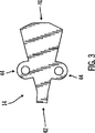
本発明の別の実施形態によると、管腔チューブ12の外径は0.140インチ未満である。本発明のさらに別の実施形態によると、管腔チューブ12の外径は約0.130インチである。本発明の一実施形態による管腔チューブ12の内部が図2に示される。図2では、センサ管腔30、薬剤管腔32、および血液管腔34の3つの管腔が、管腔チューブ12の内部に形成されている。図のように、管腔は管腔チューブ12内で独立した経路を形成する。管腔は、管腔チューブ12の内部に種々の方法で形成できる。たとえば、図示される実施形態では、センサ管腔30、薬剤管腔32、および血液管腔34はシリコンから押し出し成形されている。しかし、カテーテルの用途および環境によって、その業界で適切な管腔チューブの形成方法を使用しても良く、これに限られるわけではないが、押し出し成形、成型、機械加工、またはその組み合わせなどが挙げられる。さらに、カテーテルにシリコン以外の材料を使用しても良く、これに限られるわけではないが、ポリウレタン、ポリエチレン、テフロン(登録商標)、PVC、エラストマ、ヒドロゲル等が挙げられる。たとえば、一般にいずれも特殊な目的を持つ5つの管腔を備えたスワン−ガンツ(Swan-Ganz)カテーテルを本発明の実施形態と使用する場合には、センサのための位置を設けるようにさらに管腔を加えるように変更しても良い。従って、スワン−ガンツカテーテルはセンサを収容するように6つの管腔を備えるように製造しても良い。さらに、センサの大きさを管腔の大きさに合わせるように変更しても良い。本発明の実施形態は、末梢挿入型中心カテーテル(PICC)ラインと使用することもできる。PICCラインは中心ラインカテーテルと似た方法で製造できるが、本発明の実施形態によると、より小さく、長くてもよい。本発明の実施形態はまた、2管腔中心ラインカテーテルと使用することもできる。たとえば、本発明の実施形態を2管腔中心ラインカテーテルに適用する場合、カテーテルは注入物のための管腔を1つとセンサのための管腔を1つ備えても良い。管腔チューブ12の内部に形成される管腔は種々のサイズおよび形状としても良い。たとえば、図2に示されるように、センサ管腔30はその横の寸法が縦の寸法よりもわずかに長い、すなわち、やや楕円形となるように押し出し成形されている。この実施形態によると、センサ管腔30はそこに配置されるセンサリード22の性質のために、このように形成されている。たとえば、センサリード22内にゆるい状態の部品がある場合もあるため、センサ管腔30はセンサリード22の圧力ばめとなるように形成しても良い。従って、この特定の実施形態ではセンサ管腔30を楕円形としている。楕円形とすることで以下のように圧縮しやすくしている。すなわち、横方向では管腔のサイズはセンサの横方向のサイズと同じであるが(この方向には「ゆるい状態の部材」はない)、縦方向(この方向にセンサは組み立てられたゆるい部材を有する)では、センサがぎゅっと押されて配置されるように管腔は小さくなっている。しかし、センサ管腔30または管腔チューブ12の内部に存在しうる他の管腔のいずれも、その用途に応じて別の形状としても良い。薬剤管腔32および血液管腔34も、その用途の性質を促進するような形状にされている。たとえば、薬剤管腔32も血液管腔34も楕円形のような形状に形成されたセンサ管腔30に沿って存在するため、薬剤管腔32および血液管腔34の各々のある一面の一部もまた、薬剤管腔32および血液管腔34の湾曲部がセンサ管腔30の輪郭に沿うように、幾分楕円形となるように形成されている。これによって、カテーテルの全体の外径を最小にしながら、管腔の断面積(または体積)を最大にすることができる。血液管腔34は、用途によってはガイドワイヤの周りに配向する必要があるため、管腔チューブの寸法内で体積を最大にするような構成にしても良い。カテーテルは可撓性があるため、カテーテルを患者の体内で巧みに操作するのが難しいことがある。実用においては、まず硬いガイドワイヤを患者に挿入してから、ガイドワイヤが最終的に管腔の内部に位置するようにカテーテルをガイドワイヤの周りに配向することによって、患者の体内へとカテーテルを操作するのが望ましい場合がある。一旦カテーテルが所望の位置に置かれると、カテーテルのみを適切な位置に残したまま、ガイドワイヤは抜去されてもよい。さらに、図2に示される実施形態によると、血液管腔34は、鋭い角、すなわち「停滞領域」をできるだけ最小にするように構成される。「停滞領域」とは管腔において血液が凝固し得るおそれのある部分を指す。一般に凝血は望ましくない影響をもたらすため、凝血を防ぐために血液管腔34は鋭い角を最小にするような構成にされる。管腔チューブ12の内部における管腔の物理的な位置は種々の要因に依存する。たとえば、上述のように、図2に示される実施形態において、薬剤管腔32および血液管腔34の位置は、センサ管腔30の位置および形状に依っても決まる。さらに、図2に示される実施形態において、薬剤管腔32および血液管腔34は、その間に支柱36が形成されるように配置されている。支柱36はセンサ管腔30にさらに強度を与えることができ、これはたとえばセンサリード22の遠位端(感知要素24が位置する)が管腔チューブ12の端部より向こうに延在しない場合には有利となろう。一般に、管腔チューブ12の内部に形成される管腔は、その管腔チューブ12の内部に使用されている材料から、管腔チューブ12の内部における構造的要素となるように形成されてもよい。さらに、薬剤管腔32および血液管腔34は、たとえば多管腔カテーテルの製造を簡単にするように同じ部位から管腔チューブ12の外に出るように形成されてもよい。しかし、薬剤管腔32および血液管腔34は同じ部位から出る必要はなく、多管腔カテーテルの用途によって異なる部位から出ても良い。「下流の」出口部位があることによって、センサの読みとりが妨害されることを防げるかもしれないが、センサ情報を乱されることなく「上流の」出口部位を設けることが可能である。たとえば、本発明の実施形態にスワン−ガンツカテーテルを適用する場合、スワン−ガンツカテーテルを用いて、既知温度の低温溶液を注入する「低温流体希釈法」で心拍出量を測定してもよい。温度は下流の既知の地点で測定されても良い。その温度差が、時間に基づいて最初の注入地点から温度測定地点までを流れる流体の体積に基づく。管腔は異なる部位から出るように種々の方法で形成できる。たとえば、停滞した出口部位は、1)1つの管腔に後ろが充填された先端を形成し、スタンピングされた側面開口部を形成する、2)チューブを切るか短い管腔を成形することで1つの管腔を「早く」終端させる、または3)(側面の出口部位または短い管腔のいずれかを介した)流体の流れを付ける、接着された「ノーズコーン」を形成することによって、形成してもよい。センサリード22および感知要素24もまた、管腔チューブ12に対して種々の位置に置いて良い。たとえば、感知要素24が管腔チューブ12の一方端にあるように、センサリード22を管腔チューブ12の近位に配置しても良い。感知素子24をこのような位置に置く場合、本発明の一実施形態では、カテーテル先端の位置がX線で特定できるようにX線に対して放射線不透過の管腔チューブ12の端部にチューブを設けるのが有利かもしれない。感知要素24が管腔チューブ12の遠位に配置される場合には、これ自体がX線で見えるため、その位置はX線で簡単に特定できる。本発明の一実施形態による接合要素14の詳細が図3に示される。図3の接合要素14は、第1の接合要素端40と、第2の接合要素端42と、縫合タブ44とを含む。図3に示される実施形態では、第1の接合要素端40は、種々のチューブおよび取り付け具を収容できるだけの十分な大きさで、弧状となっている。第2の接合要素端42は第1の接合要素端40と比較するとかなり狭く、図示される実施形態で使用されるセンサチューブおよび2つの注入ラインチューブを収容できる大きさに形成される。しかし、第1の接合要素端40および第2の接合要素端42の双方とも、カテーテルを使用する環境の性質によって、種々の形状およびサイズに形成可能である。縫合タブ44は、医療従事者が接合要素14を患者に縫合する、または他の何らかの表面に装着するのに使用してもよい。このように、使用中にカテーテルが動く危険性を最小にしている。縫合タブ44の代わりに、またはこれに加えて、接合要素14を患者または他の表面に固定するのに別の手段を用いても良い。たとえば、接合要素14はカテーテルを患者に固定しやすくするような別のタイプのタブまたは他の何らかの要素を備えて形成されても良い。たとえば、縫合タブ44は機械的に縫合されるのではなく、接着性を持たせても良い。さらに、タグにおいて縫合部が剪断される危険性を最小にするのであれば、他の形状であってもよい。接合要素14は種々の材料から形成できる。たとえば、本発明の一実施形態によると、接合要素14は液体シリコンゴムから形成されるが、種々のプラスチックまたは他の材料を使用しても良い。さらに、接合要素14は図3に示す形状に限られるわけではない。接合要素14はその使用をしやすくするいかなる形状に形成しても良い。図4は、接合要素14と管腔チューブ12の間の結合の詳細を示す。接合要素14は種々の方法で管腔チューブ12に装着できる。たとえば、本発明の一実施形態によると、管腔チューブ12は圧力ばめによって接合要素14に接合されても良い。本発明の別の実施形態によると、接合要素14は接着剤を用いて管腔チューブ12に接着されても良い。適切な接着剤には、これに限られるわけではないが、医療用シリコン接着剤または他の医療用接着剤などがある。接合要素14および管腔チューブ12を製造するのに使用する材料に依って、接合要素14と管腔チューブ12の接着接合を促進するのにプライマが必要な場合もあるだろう。適切なプライマは、これに限られるわけではないが、ヘプタンまたは他の溶剤で希釈した接着剤を含む。接合要素14内には、第1の注入チューブ16、第2の注入チューブ18、およびセンサライン20が配置される。第1の注入チューブ16、第2の注入チューブ18、およびセンサライン20は、管腔チューブ12内のその関連の管腔から接合要素14の広がった部分に延在する。本発明の一実施形態によると、チューブはその関連の管腔に接着剤で装着されても良い。
本発明の別の実施形態では、チューブは所定の位置に成形されても良い。接合要素14の広くなった端部において、第1の注入チューブ16および第2の注入チューブ18は注入チューブコアピン50にはめ込まれるが、センサチューブ20はセンサチューブコアピン52にはめ込まれる。注入チューブコアピン50およびセンサチューブコアピン52は、第1の注入チューブ16、第2の注入チューブ18、およびセンサチューブ20が接合要素14を介して管腔チューブ12内のその関連の管腔に延びる際に、その形状および位置を保つようにしている。さらに、注入チューブコアピン50およびセンサチューブコアピン52は、広い表面でそれぞれ注入ラインおよびセンサリードを装着するようになっている。注入チューブコアピン50およびセンサチューブコアピン52は、これに限られるわけではないが、ステンレス鋼、チタン、デルリン、テフロン(登録商標)、または何らかの金属または無孔プラスチックを含む種々の材料から形成できる。どの材料を用いても、高温での移送のための高い融点、または低温での成形のための低い融点を持つものでなくてはならない。本発明の一実施形態による注入部材26が図5に示される。この例示的な注入部材26は注入部材リードチューブ60と、張力緩和チューブ62と、雌ルアー取り付け具64と、雄ルアーキャップ66と、雄ルアー注射部位68とを含む。注入部材26とともにチューブクランプ69を使用しても良い。いかなる適切なチューブクランプ構造を使用しても良く、これに限られるわけではないが、図5に示すようなバネ作用クランプ69、ピンチクランプ、スライドクランプ、ローラクランプ等を使用しても良い。注入部材リードチューブ60はシリコンチューブを含んでも良く、一般にコアピンに挿入される。張力緩和チューブ62は、注入部材リードチューブ60の上部を伸ばし、チューブ62と注入部材リードチューブ60をルアー取り付け具64に固定することにより、注入部材リードチューブ60と雌ルアー取り付け具64の間の接合を支える。カテーテルに適切な材料はいずれも、張力緩和チューブ62にも適切である。注入部材26における注入物の流れを規制する必要がある場合には、注入部材26または張力緩和チューブ62の変形可能な位置の上にチューブクランプ69を配置して、注入部材26を締め付け、注入部材26内の注入物の流れを規制しても良い。張力緩和チューブ62はまた、クランプが長時間固定される場合に、より内側の(かつより細い)注入部材リードチューブ60が永久的に変形してしまわないように、チューブクランプ69を保持する。さらに、チューブクランプ69を保持することにより、注入部材リードチューブ60は、疲労応力(たとえば繰り返しチューブクランプ69を開閉したり、注入チューブの動き、またはIV注入の際に注入チューブを引っ張ったりすることによる)や、取り付け具から誤ってチューブが動いてしまうことに対して、より左右されにくくなるであろう。注入部材26を使用しないときには、雄ルアーキャップ66を雌ルアー取り付け具64に挿入しても良く、患者に注入物を注射する必要ができた場合に、雄ルアーキャップ66の代わりに、雄ルアー注射部位68を使用しても良い。図5に示される実施形態ではルアー取り付け具が使用されているが、注入部材26とともに、たとえば、ロッキング取り付け具等の、その用途に適切ないかなるタイプの取り付け具を使用しても良い。さらに、雄ルアーキャップ66は、針またはIV点滴システムを受けるのに使用できるラテックスまたは非ラテックスの隔壁または注射部位を有しても良い。さらに、雄および雌の取り付け具を図5に示す構成と逆にしても良い。注入部材26とその関連のキャップ、取り付け具、ロック等は識別しやすいように色分けしても良い。たとえば、血液に使用する注入部材26を赤と色分けし、薬剤、ブドウ糖、または他の薬物に使用する注入部材26を白と色分けしても良い。
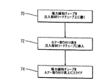
本発明の一実施形態による注入部材26の組み立て方法を図6に示す。ステップ70で、張力緩和チューブ62を注入部材リードチューブ60の上に置く。このステップを簡単にするために、張力緩和チューブ62の中空の部分は、注入部材リードチューブ60の直径を収容できるだけの大きさであるが、所望の張力緩和機能を果たすのに効率が悪いほどの大きさとはしない必要がある。ステップ72において、雌ルアー取り付け具64を注入部材リードチューブ60に挿入する。雌ルアー取り付け具64の位置は、雌ルアー取り付け具64と注入部材リードチューブ60の間の圧縮および摩擦によって維持されても良い。雌ルアー取り付け具64が注入部材リードチューブ60に挿入されると、ステップ74で張力緩和チューブ62は雌ルアー取り付け具64の方へスライドして戻し、雌ルアー取り付け具64の注入部材リードチューブ60に挿入された部分を完全に覆うようにする。図6に示された方法を用いると、接着剤を用いることなく、注入部材26を簡単に組み立てることができる。しかし、他の実施形態で、注入部材26を組み立てるのに接着剤を使用しても良い。さらに別の実施形態で、カテーテルを完全に成形、すなわちプラスチックの取り付け具を注入ライン/接合/遠位チューブの型に成形しても良いし、取り付け具を完全な部品の型に成形しても良い。本発明の一実施形態による多管腔カテーテルアセンブリを組み立てたものを図7に示す。雄ルアーキャップ66を雌ルアー取り付け具64に挿入し、次にこれを注入部材リードチューブ60に挿入する。張力緩和チューブ62によって雌ルアー取り付け具64と注入部材リードチューブ60の間の接合部を覆う。注入部材リードチューブ60を、接合要素14内にある注入チューブコアピン50に挿入する。注入チューブコアピン50は第1の注入チューブ16および第2の注入チューブ18に装着しても良い。接合要素14内にあるセンサチューブコアピン52がセンサチューブ20に装着される。第1の注入チューブ16、第2の注入チューブ18、およびセンサライン20は接合要素14を通ってそれぞれ第1の注入管腔32、第2の注入管腔34、およびセンサ管腔30へと延びる。接合要素14内において、第1の注入チューブ16、第2の注入チューブ18、およびセンサチューブ20を所定の位置において接着剤で接着しても良いし、またはそのそれぞれの相対位置において維持しても良い。接合要素14は管腔チューブ12に接着されても良いし、装着されても良い。たとえば、本発明の一実施形態によると、管腔チューブ12は角度をなしてコアピン上で接合要素14に成形され、コアピンが型内で管腔チューブ12を伸ばして開き、簡単には引っ張り離すことができないような機械的な締まりばめを形成しても良い。接合要素14はまた縫合タブ44を備えるように構成される。このように、図7に示される本発明の実施形態は、感知素子を有するセンサリードを取り付けるとすぐに使える状態である。管腔チューブ12を患者に挿入して、縫合タブを患者に縫合し、患者に注入物を送達するための薬剤および血液注入ラインにルアー取り付け具を装着しても良い。センサリード22がその関連の電子機器に接続されると、患者への注入物の送達が自動的に監視、制御されてもよい。図8aは本発明の一実施形態によってセンサリード20にどのように印を付けてもよいかを示す。図8aに示すように、センサ上にセンサスケール82を設けても良い。センサスケール82は一般に、センチメートル等の長さの要素で印を付けられるが、センサスケール82にはその特定の用途にとって望ましい、いかなる単位で印を付けても良い。センサスケール82はインクまたは他の永続するマーキングで印を付けても良い。したがって、管腔チューブ12がたとえばシリコン等の透明または部分的に透明な材料で形成される場合、センサライン20にインクで付与されたセンサスケール82は管腔チューブ12を通して直接見ることができる。本発明の別の実施形態において、外側に印を付けられた、またはさらに定義するために後でインクで付与されたものを伴う、不透明の部分に成形された印を備えた不透明なチューブを使用しても良い。本発明の一実施形態により、図8bに示すように、注入部材26もまた識別するようにしても良い。たとえば、リードチューブ識別表示84で注入部材リードチューブを識別しても良い。図8に示される実施形態において、リードチューブ識別表示84は関連する管腔の実際のゲージ、たとえばこの場合には18ゲージを示す。さらに、クランプ部位識別表示86で張力緩和チューブ62を識別しても良い。クランプ部位識別表示86は、手作業で配置してもよいチューブクランプ69の部位を目視的に示すものである。
図9は、本発明の一実施形態によって患者に埋め込まれた状態の多管腔カテーテル10を示す。体内への多管腔カテーテル10の挿入は鎖骨下静脈、内頸静脈を介して、または他の適切な態様で行われても良い。図9に示される実施形態においては、鎖骨下静脈から挿入している。したがって、多管腔カテーテル10は経皮的部位90から挿入し、鎖骨92の下を通す。多管腔カテーテル10は鎖骨下静脈を通り、センサ先端24が内科医の所望の位置にあるようなところまで延びるが、これは患者91の大きさおよび身体的特徴によっても決まる。接合要素14は、患者91の肩の広近傍領域に存在する。ルアー取り付け注入口93およびセンサ延長ラインコネクタ95は患者の体外にあり、それぞれ注入ラインおよびセンサ電子機器94に接続されても良い。センサ延長ライン94は生体内ブドウ糖モニタまたはパーソナルポンプコミュニケータ等の経皮モニタ96に接続されても良い。経皮モニタ96は、たとえば、弾力性のあるアームバンド98を使用すること等によって患者に装着されても良い。図9に示される実施形態によると、たとえば糖尿病患者が集中治療、または他の救命医療、もしくは診療状況にある場合、患者への1以上の注入物の制御、送達を自動監視するために患者に多管腔カテーテル10を取り付ける場合がある。たとえば、多管腔カテーテル10を鎖骨下静脈を通して経皮的に患者に挿入しても良い。センサリード22を右心房接合部等の体内の所望の位置に送っても良い。このように、感知要素24は、ブドウ糖監視等のパラメータ監視に適切な位置にあっても良い。感知要素24は管腔チューブ12の端部から数インチ先まで延在してもよいし、管腔チューブ12の端部まで延在しても良い。このように、センサリード22が生体内の位置にあっても、医療従事者は、接合要素14の近傍にある体外のセンサリード22上の印を観察することによって、センサリードが体内のどこまで延在しているかを突き止めることができる。患者の体外にある接合要素14は、縫合タブ44を用いて肩領域の広近傍領域において患者に縫合されても良い。注入部材26に注入物送達システムを接続し、一方でセンサリード22の外部部分を電子機器に接続しても良い。電子機器によって作動されると、感知要素24はブドウ糖または他のパラメータを感知でき、これを電子機器によって読みとる。電子機器は、たとえば血液、ブドウ糖、他の薬物等の注入物を注入部材26に送達するための注入物送達システムを制御してもよい。注入物は注入部材26を介して注入管腔32,34へと運ばれ、管腔32,34が終端する管腔チューブ12の端部からカテーテルを出て、患者に必要な処置を施す。本発明の実施形態は経皮使用されてもよいし、埋め込まれてもよい。たとえば、多管腔カテーテル10は経皮使用されてもよいし、完全に埋め込まれてもよい。本発明の一実施形態による腹膜で使用するためのインシュリン送達カテーテルとセンサを組み合わせたものが図10に示される。図10に示される本発明の実施形態は、これに限られるわけではないが、ブドウ糖センサであってもよいセンサ120と、インシュリン送達カテーテルであってもよい送達カテーテル122と、インシュリンポンプであってもよいポンプ124と、一体となったセンサおよびカテーテルヘッダ126とを含む。図10に示される実施形態では、ブドウ糖センサ120とインシュリン送達カテーテル122は経皮使用されてもよいし、埋め込まれてもよい。インシュリンポンプ124とセンサおよびカテーテルヘッダ126が埋め込まれるように設計される場合、図10に示される本発明の実施形態全体が患者に埋め込まれてもよい。インシュリンポンプ124とセンサおよびカテーテルヘッダ126が埋め込まれるように設計されない場合、インシュリン送達カテーテル122とブドウ糖センサ120の組み合わせが体内に経皮的に挿入され、体外へと延び、センサおよびカテーテルヘッダ126およびインシュリンポンプ124に装着されてもよい。さらに、図10に示される本発明の実施形態は腹膜での用途に使用されてもよい。本発明の実施形態はまた、単管腔カテーテルに向けられてもよい。たとえば、本発明の実施形態は、経皮的装置として使用され、他の管腔を持たない単管腔装置を含んでもよい。その単一の管腔はセンサのために使用しても、注入物のために使用してもよい。たとえば、本発明の一実施形態によると、単管腔カテーテルは、経皮的装置に使用するセンサを含んでもよい。このように、センサを体内に挿入しながら、さらに体外に延び、監視または制御用電子機器または他の装置に接続してもよい。センサは後に除去されるスリーブとともに挿入されてもよいし、スリーブ内に含まれてもよい。センサは一定期間体内に留められてもよい。本発明の実施形態による単管腔カテーテルでは、単管腔カテーテルは多管腔カテーテルについて上述した要素を含んでもよい。たとえば、単管腔カテーテルは、その内部に管腔を備えた管腔チューブと、接合要素と、管腔チューブの内部の管腔に接続されたセンサチューブと、センサリードを含んでもよい。センサリードの遠位端に感知要素を含んでもよい。単管腔カテーテルはまた、ルアー取り付け具およびルアーキャップを含んでもよい。本発明の実施形態は、連続的、断続的、またはほぼ連続的に身体的特徴を測定する内蔵式被分析物および/または治療センサを備えた改良された中心ラインカテーテルに向けられてもよい。改良された中心ラインカテーテルに加え、本発明の実施形態はまた、改良されたスワン−ガンツカテーテルまたはPICCラインに向けられてもよい。
図11は本発明の好適な実施形態による被分析物センサ114を備えた中心ラインカテーテル100を示す概略図である。中心ラインカテーテルは当該分野でよく知られており、一般に病院の集中治療室(ICU)/緊急治療室において患者にカテーテルの1以上の管腔を介して薬物を送達するのに使用される(異なる薬物には異なる管腔を使用する)。中心ラインカテーテル100は一般に一方端で注入装置(たとえば注入ポンプ、IV点滴、または注射器の開口部など)に接続され、他方端は患者の心臓付近の大動脈や静脈の一つに挿入され、薬物を送達する。注入装置(図示せず)は、これに限られるわけではないが、塩水、薬剤、ビタミン、薬物、たんぱく質、ペプチド、インシュリン、神経伝達物質など、患者の必要に応じた薬物を送達する。別の実施形態では、中心ラインカテーテルは、腹膜内の領域、リンパ腺、皮下、肺、消化管等のいかなる体内の空間または管に使用されてもよく、血液以外の体液の被分析物の測定または治療の判断を行ってもよい。図11の中心ラインカテーテル100は、2管腔カテーテルとして図示されている。本発明の好適な実施形態において、被分析物センサ114は中心ラインカテーテル100の1管腔110に組み込まれ、ユーザの血液および/または体液の特徴レベルを測定する。好適な実施形態では、被分析物センサ114は、ここに引用により援用する米国特許第4,650,547号、第4,671,288号、第4,781,798号、第4,703,756号、第4,890,620号に一般的に説明されるようなブドウ糖センサである。しかし、本発明のさらに別の実施形態として、ホルモン、コレステロール、薬物、濃度、ウイルス量(HIVなど)等の他の物質、特徴、または組成のレベルを測定してもよいことが理解されるであろう。したがって、本発明の実施形態は主に、糖尿病/糖尿病的症状の治療に使用されるブドウ糖センサに関して説明しているが、本発明の実施形態は、生理学的特徴がICUにおいて監視される広範囲の患者治療プログラムに適用できる。図11に示されるように、センサ114は中心ラインカテーテル100の第1の管腔110内に配置される。第1の管腔110内にはオリフィス112があり、血液がセンサ114と接触し、センサ114がデータを収集できるようになっている。センサ114は次にセンサコネクタ102を介して監視システム(図示せず)に情報を送り、ここでデータを処理、表示する。監視システムは血液性状をリアルタイムまたはほぼリアルタイムで呈示し、患者の状態をすぐに監視できるようになっている。ブドウ糖センサ114は、ある好適な形態では、一般に、一般的な改良された埋め込み可能酵素電極を含む。これは米国特許第4,650,547号、第4,671,288号、第、4,781,798号、第4,703,756号、第4,890,620号に記載されており、より最近では、2001年12月31日出願の「センサ基板およびその製造方法」と題された米国特許出願第10/038,276号、2001年12月28日出願の「感知装置およびプロセス」と題された米国特許出願第10/036,093号、および2001年12月28日出願の「埋め込み可能なセンサ電極および電子回路」と題された米国特許出願第10/034,338号に記載されており、これらをここに引用により援用する。このような酵素電極は血液等の患者の体液と直接接触するためのセンサ先端部を含む。センサ先端部は、一般に酸素(O2)の存在下でブドウ糖に触媒作用を及ぼすブドウ糖酸化酵素の使用に伴う酵素反応に対する流体の導電性の変化を測定するための導電性センサを規定する。導電性信号がセンサ114から導体を介してセンサ114の近位端に、さらにセンサコネクタ102を介して監視システムに伝送される。別の実施形態において、これに限られるわけではないが光センサ等の別のセンサ技術を使用しても良い。好適には、埋め込み可能光センサは、光学変化を起こしたり、蛍光発光したりする等の光反応性物質または化合物、またはブドウ糖等の体液被分析物の存在下で変化する特性を検出できる他の何らかの適切な化合物を含む。化合物はまた、マーカー物質等の摂取、注射、または体内に入れられた被分析物のレベルを検出するのにも使用できる。たとえば、これに限られるわけではないが、体液被分析物の存在下で蛍光変化を生じる使用可能な化合物が、1996年4月2日Jamesらに発行された「糖類の検出で使用するのに適した蛍光化合物」と題された米国特許第5,503,770号、1996年4月30日Russellらに発行された「ポリヒドロキシル化合物検出方法および手段」と題された米国特許第5,512,246号、Van Antwerpらの「侵襲性が最小の化学増幅光グルコースセンサ」と題された米国仮出願第60/007,515号、Van Antwerpらの「化学増幅を利用した生体分子の検出」と題された米国特許第6,011,984号に開示されており、これら全てをここに引用により援用する。ドナー・アクセプタ蛍光技術を利用した他の化合物を使用しても良く、たとえば、1997年5月13日Raoらに発行された「経皮的な被分析物監視を行う方法および装置」と題された米国特許第5,628,310号、1994年8月30日Chickらに発行された「体液におけるブドウ糖を検出、定量化する方法および装置」と題された米国特許第5,342,789号、1993年9月21日Lakowiczらに発行された「発光期間およびエネルギ伝達による糖類の測定および定量化」と題された米国特許第5,246,867号に記載されており、これら全てをここに引用により援用する。センサがブドウ糖センサであり、測定すべき特徴が血中ブドウ糖(血糖)レベルである好適な実施形態において、ブドウ糖モニタは一般に、2000年2月23日出願の「ブドウ糖モニタ較正方法」と題された米国特許出願第09/511,580号に記載されているタイプのものであり、これをここに引用により援用する。別の実施形態においては、ブドウ糖モニタは一般に、1999年8月19日出願の「遠隔測定される特徴モニタシステムおよびその使用方法」と題された米国特許出願第09/377,472号に記載されているタイプのものであり、これをここに引用により援用する。
好適な実施形態では、モニタシステムは、センサ114に装着されて未処理のセンサデータを記録するモニタと、モニタが記録したデータをダウンロードし、評価するためのプログラミング命令およびソフトウェアを含むデータプロセッサ(図示せず)との両方を含む。しかし、別の実施形態において、監視処理用の電子機器は別々の装置に組み込まれても良い。さらに、好適な実施形態では、モニタシステムはセンサ114から未処理のデータを取り、リアルタイムでそれを評価するが、未処理データを後に処理またはデータプロセッサにダウンロードするようにモニタシステムが未処理のデータを記憶してもよい。別の実施形態において、監視システムは、ブドウ糖モニタからダウンロードによって受けた未処理のブドウ糖センサデータの計算結果を表示するのに使用するディスプレイを含んでも良い。表示される結果及び情報は、これに限られるわけではないが、特徴の傾向を示す情報(ブドウ糖の変化速度など)、履歴データのグラフ、平均特徴レベル(ブドウ糖など)、安定化および較正情報、未処理データ、表(日付、時間、サンプル番号、対応する血糖レベル、警告メッセージ等と相関する未処理データを示す)などを含む。別の実施形態において、モニタシステムを他の医療装置と組み合わせて、共通のデータネットワークおよび/または遠隔測定システムを介して他の患者データを受けるようにしてもよい。たとえば、ブドウ糖モニタを血糖測定器と組み合わせて、ブドウ糖較正基準値を直接取り入れたり、相関させても良く、たとえば、1999年6月17日出願の「特徴メータを備えた特徴モニタとその使用方法」と題された米国特許出願第09/334,996号に記載されており、ここに引用により援用する。ブドウ糖モニタは、米国特許番号第4,562,751号、第4,678,408号、第4,685,903号に概説されているような外付けタイプの半自動薬物注入ポンプや、米国特許番号第4,573,994号に概説されているような埋め込み可能な自動薬物注入ポンプや、病院のIV注入システムと組み合わせても良く、上記の文書をここに引用により援用する。ブドウ糖モニタは注入ポンプからのデータを記録しても良いし、かつ/またはブドウ糖センサ114と注入ポンプの双方からのデータを処理して、ブドウ糖センサ測定値に基づいて注入ポンプを制御する閉ループシステムを確立しても良い。別の実施形態として、別の身体的特徴が監視され、モニタは閉ループシステムにおけるフィードバックを与えて、薬剤送達速度を制御するように使用しても良い。図11に示すように、心臓付近の大動脈または静脈に直接薬物を投与するために中心ラインカテーテル100に第2の管腔106が設けられる。好適な実施形態では、オリフィス108を用いて血流に薬物を放出し、ルアー取り付け具104を用いて注入ポンプ、IV点滴、または注射器の開口部と接続するが、別の実施形態においては、第2の管腔106に2つ以上のオリフィス108を形成し、血流に薬物を放出するようにしても良い。さらに、第2の管腔106と注入装置の間の接続用取り付け具は、ルアー取り付け具104の代わりに、ジャック/プラグの組み合わせに似たプラグインコネクタ、隔壁キャップ、または他の類似装置であってもよい。好適な実施形態では、第2の管腔106のオリフィス108が、第1の管腔110のセンサオリフィス112よりも中心ライン100の近位端に近く設定された距離に配置される。センサオリフィス112と比較してオリフィス108が血流のさらに下流にあるようにすることで、センサ114によって得られた読みとり値がオリフィス108からのどの形態の薬物の送達によっても乱されたり、歪曲されないことが確実となる。図12は被分析物センサ114とともに中心ライン100を用いて行った研究で、薬剤注入(または他の何らかのタイプの注入)とセンサの読みとりの間にいかなる干渉も起こらないことを実証している。図12の研究は、ブドウ糖センサ114を用いて、デキストロース溶液(すなわち濃縮ブドウ糖溶液)を末梢位置を介して投与した(すなわち伏在静脈注入)場合に、中心ラインカテーテル100を介した投与に対してなんらかの差があるかを検出したものである。この研究によって、本発明の中心ラインカテーテル100を用いた場合に、センサ114とデキストロース溶液の送達の間に干渉がなかったことが示された。デキストロースが中心ラインカテーテル100を介して投与されたときにブドウ糖の数値が急増すると、干渉が検出されたことになる。好適な実施形態では、2管腔中心ラインカテーテルが図示されているが、中心ラインカテーテル110にさらに任意の数の管腔を加えても良い。
図13および図14は、本発明の好適な実施形態による中心ラインカテーテルの別の実施形態を示す。図13および図14に示すように、中心ラインカテーテルに複数の注入管腔および複数のセンサを設けても良い。この付加的な管腔は、他のタイプの流体、たとえば、これに限られるわけではないが、塩水、ビタミン、薬剤、薬物、蛋白質、ペプチド、インシュリン、神経伝達物質等を患者の必要に応じて送達するように使用できる。患者の体から種々の異なる特徴を検出するためにさらにセンサを加えても良い。さらに、別の実施形態において、他の機能を行うようにさらに管腔を使用しても良い。たとえば、図11の第1の管腔110または第2の管腔106内にさらにより小さな管腔を設け、凝固物質、蛋白質、脂肪、または他の血液中の物質がオリフィス108および112を覆いがちな場合に、塩水または他の適切な清浄液を送達してオリフィス108または112を清浄するようにしてもよい。または、2001年12月27日出願の「埋め込み可能なセンサ洗浄スリーブ」と題された米国特許出願第10/034,740号に記載されるように、中心ラインカテーテル100全体の周りに洗浄スリーブを配置しても良く、この出願をここに引用によって援用する。洗浄スリーブはセンサが読みとりを行うところ、かつ/または中心ラインカテーテルが薬物を送達するところに向けたオリフィスを有する。図15は、本発明の好適な実施形態による図11の線#1に沿った中心ラインの断面図である。図15は第2の管腔106の封止されていない部分が第1の管腔110内のセンサの位置を過ぎていかに延在し、センサのオリフィス112が注入オリフィス108の下流に確実に配置されるようにされるかを示している。図16は、本発明の好適な実施形態による図11の線#2に沿った中心ラインの断面図である。図16は、2管腔カテーテルの一般的なサイズを大きくすることなく、センサ114を含むように中心ラインカテーテル100をいかに変更できるかを示している。センサ114を含む第1の管腔110の長さ部分に沿って第2の管腔106のサイズを縮小することにより、センサ114を中心ラインカテーテル100内に容易に収容できる。このように、被分析物センサを中心ラインカテーテル内で組み合わせて、患者の体内での生体内被分析物レベルを測定する一方で、中心ラインカテーテルを介して他の流体を投与することができる。好適な実施形態ではセンサを介して特徴データを回収しながら薬物を投与する中心ラインカテーテルの機能について説明したが、他の機能を果たすように装置に変更を加えることが可能である。中心ラインカテーテルはまた、患者の体から直接サンプルを取るように使用することもできる。このように、感知し、サンプルを取り、注入することができるため、広範囲にわたる診断および治療上の選択肢が生まれる。さらに、この特徴の種々の組み合わせを用いることも可能である。たとえば、中心ラインカテーテルは、注入しているものを感知したり、感知しているものに対して好影響または悪影響を与える物質を注入することもでき、または感知、注入、サンプル採取は関連がなくても良い。本発明の特定の実施形態を図示し、説明したが、当業者には、本発明は図示、説明した特定の実施形態に制限されるものではなく、添付の特許請求の範囲の精神および範囲を逸脱することなく変更および変形を加えられることが理解されるであろう。
In the following description of the preferred embodiments, reference is made to the accompanying drawings that form a part hereof, and in which are shown by way of illustration specific embodiments in which the invention may be practiced, although other embodiments may be utilized. It will be understood that structural changes may be made without departing from the scope of the invention.
A generalized
According to another embodiment of the present invention, the outer diameter of the
In another embodiment of the present invention, the tube may be molded in place. At the widened end of the joining
A method of assembling the
FIG. 9 shows a
FIG. 11 is a schematic diagram illustrating a
In a preferred embodiment, the monitor system is a data processor (FIG. 1) that includes a monitor that is attached to
Figures 13 and 14 show another embodiment of a central line catheter according to a preferred embodiment of the present invention. As shown in FIGS. 13 and 14, the central line catheter may be provided with multiple infusion lumens and multiple sensors. This additional lumen may contain other types of fluids such as, but not limited to, saline, vitamins, drugs, drugs, proteins, peptides, insulin, neurotransmitters, etc. as the patient requires. Can be used to deliver. Additional sensors may be added to detect a variety of different features from the patient's body. Further, in other embodiments, additional lumens may be used to perform other functions. For example, an even smaller lumen may be provided in the
Claims (23)
複数の第2のチューブと、
前記第1のチューブの一端側と複数の前記第2のチューブの一端側とが取り付けられ、前記第1のチューブに配置される前記複数の管腔の各第1端と前記複数の第2のチューブの内の各前記第2のチューブの各一端との間の接続を維持する接合要素と、
先端側にセンサ要素を含み、前記センサ管腔に接続されている前記第2のチューブを通して前記第1のチューブに配置される前記センサ管腔の第1端から第2端に向かって延びるセンサリードと、を含む多管腔カテーテルであって、
前記センサ管腔の断面の一部は前記センサリードの外径よりも小さい第1の長さを含み、前記センサ管腔は前記第1の長さの方向に前記センサリードを圧縮し、
前記センサ要素は前記第1のチューブの他端において前記第1のチューブから出ることができ、前記センサリードの前記先端は前記第1のチューブの前記他端を越えて延びると共に前記各管腔の第2端を越えて延びることができること、
を特徴とする多管腔カテーテル。A first tube, each having a first end and a second end, in which a plurality of lumens including a sensor lumen are disposed;
A plurality of second tubes;
One end side of the first tube and one end side of the plurality of second tubes are attached, and each of the first ends of the plurality of lumens arranged in the first tube and the plurality of second tubes A joining element that maintains a connection between each end of each said second tube within the tube;
A sensor lead including a sensor element on a distal end side and extending from a first end to a second end of the sensor lumen disposed in the first tube through the second tube connected to the sensor lumen A multi-lumen catheter comprising:
A portion of the cross-section of the sensor lumen includes a first length that is smaller than an outer diameter of the sensor lead, the sensor lumen compresses the sensor lead in the direction of the first length;
The sensor element can exit the first tube at the other end of the first tube, and the tip of the sensor lead extends beyond the other end of the first tube and each of the lumens. Being able to extend beyond the second end,
A multi-lumen catheter characterized by.
前記センサ管腔以外の前記各管腔は、前記センサ管腔側の管腔内面に略楕円形の前記センサ管腔の輪郭に沿った曲線と前記センサ管腔に向かう第1の角とを含み、前記第1のチューブの外面側の管腔内面に略円形の前記第1のチューブの外形に沿った曲線と前記第1のチューブの外面側に向かう第2の角と、を含む断面形状であることを特徴とする請求項3に記載の多管腔カテーテル。The outer cross section of the first tube is substantially circular,
Each of the lumens other than the sensor lumen includes a curve along the outline of the sensor lumen having a substantially elliptic shape on the inner surface of the lumen on the sensor lumen side, and a first angle toward the sensor lumen. , cross-sectional shape and a second corner towards the outer surface side of the first tube outer surface substantially circular first the luminal surface of the curve along the contour of the tube first tube The multi-lumen catheter according to claim 3, wherein
Applications Claiming Priority (7)
| Application Number | Priority Date | Filing Date | Title |
|---|---|---|---|
| US36094002P | 2002-03-01 | 2002-03-01 | |
| US60/360,940 | 2002-03-01 | ||
| US41424802P | 2002-09-27 | 2002-09-27 | |
| US60/414,248 | 2002-09-27 | ||
| US10/331,949 | 2002-12-30 | ||
| US10/331,949 US7500949B2 (en) | 2002-03-01 | 2002-12-30 | Multilumen catheter |
| PCT/US2003/006097 WO2003074107A2 (en) | 2002-03-01 | 2003-02-28 | Multilumen catheter |
Publications (3)
| Publication Number | Publication Date |
|---|---|
| JP2005536239A JP2005536239A (en) | 2005-12-02 |
| JP2005536239A5 JP2005536239A5 (en) | 2006-01-19 |
| JP4711627B2 true JP4711627B2 (en) | 2011-06-29 |
Family
ID=27792162
Family Applications (1)
| Application Number | Title | Priority Date | Filing Date |
|---|---|---|---|
| JP2003572618A Expired - Fee Related JP4711627B2 (en) | 2002-03-01 | 2003-02-28 | Multi-lumen catheter |
Country Status (6)
| Country | Link |
|---|---|
| US (3) | US7500949B2 (en) |
| EP (1) | EP1487529A4 (en) |
| JP (1) | JP4711627B2 (en) |
| AU (1) | AU2003213613A1 (en) |
| CA (2) | CA2747852A1 (en) |
| WO (1) | WO2003074107A2 (en) |
Families Citing this family (201)
| Publication number | Priority date | Publication date | Assignee | Title |
|---|---|---|---|---|
| US7077829B2 (en) * | 2001-01-09 | 2006-07-18 | Rex Medical, L.P. | Dialysis catheter |
| US6814718B2 (en) * | 2001-01-09 | 2004-11-09 | Rex Medical, L.P | Dialysis catheter |
| US7011645B2 (en) * | 2001-01-09 | 2006-03-14 | Rex Medical, L.P. | Dialysis catheter |
| US8323228B2 (en) | 2007-04-12 | 2012-12-04 | Rex Medical L.P. | Dialysis catheter |
| US7097635B2 (en) * | 2001-01-09 | 2006-08-29 | Rex Medical, L.P. | Guidewire retrieval member for catheter insertion |
| US6989891B2 (en) | 2001-11-08 | 2006-01-24 | Optiscan Biomedical Corporation | Device and method for in vitro determination of analyte concentrations within body fluids |
| US6758836B2 (en) | 2002-02-07 | 2004-07-06 | C. R. Bard, Inc. | Split tip dialysis catheter |
| US7393339B2 (en) * | 2003-02-21 | 2008-07-01 | C. R. Bard, Inc. | Multi-lumen catheter with separate distal tips |
| CA2523267C (en) | 2003-04-23 | 2013-09-03 | Biovalve Technologies, Inc. | Hydraulically actuated pump for long duration medicament administration |
| US20040243095A1 (en) | 2003-05-27 | 2004-12-02 | Shekhar Nimkar | Methods and apparatus for inserting multi-lumen spit-tip catheters into a blood vessel |
| WO2005065241A2 (en) * | 2003-12-24 | 2005-07-21 | Argose, Inc. | Smmr (small molecule metabolite reporters) for use as in vivo glucose biosensors |
| US8992454B2 (en) | 2004-06-09 | 2015-03-31 | Bard Access Systems, Inc. | Splitable tip catheter with bioresorbable adhesive |
| WO2006014425A1 (en) | 2004-07-02 | 2006-02-09 | Biovalve Technologies, Inc. | Methods and devices for delivering glp-1 and uses thereof |
| EP4197447A1 (en) * | 2004-08-16 | 2023-06-21 | Corindus, Inc. | Image-guided navigation for catheter-based interventions |
| US8282563B2 (en) * | 2004-11-18 | 2012-10-09 | Japan Health Sciences Foundation | Cardiac disease treatment system |
| US20060129126A1 (en) * | 2004-11-19 | 2006-06-15 | Kaplitt Michael G | Infusion device and method for infusing material into the brain of a patient |
| DE102005003632A1 (en) | 2005-01-20 | 2006-08-17 | Fraunhofer-Gesellschaft zur Förderung der angewandten Forschung e.V. | Catheter for the transvascular implantation of heart valve prostheses |
| US7785258B2 (en) | 2005-10-06 | 2010-08-31 | Optiscan Biomedical Corporation | System and method for determining a treatment dose for a patient |
| US8251907B2 (en) * | 2005-02-14 | 2012-08-28 | Optiscan Biomedical Corporation | System and method for determining a treatment dose for a patient |
| US20060253085A1 (en) * | 2005-05-06 | 2006-11-09 | Medtronic Minimed, Inc. | Dual insertion set |
| US8257302B2 (en) * | 2005-05-10 | 2012-09-04 | Corindus, Inc. | User interface for remote control catheterization |
| US7901395B2 (en) * | 2005-08-16 | 2011-03-08 | Borden Jonathan R | Catheter having staggered lumens and method |
| US9042974B2 (en) * | 2005-09-12 | 2015-05-26 | New York University | Apparatus and method for monitoring and treatment of brain disorders |
| US20090131955A1 (en) * | 2005-09-29 | 2009-05-21 | Corindus Ltd. | Methods and apparatuses for treatment of hollow organs |
| US20070213813A1 (en) * | 2005-12-22 | 2007-09-13 | Symetis Sa | Stent-valves for valve replacement and associated methods and systems for surgery |
| US7641757B2 (en) * | 2006-01-12 | 2010-01-05 | Pacesetter, Inc. | Method of making a tubular body for a catheter, sheath or lead |
| US20090143658A1 (en) * | 2006-02-27 | 2009-06-04 | Edwards Lifesciences Corporation | Analyte sensor |
| US20070219441A1 (en) * | 2006-02-27 | 2007-09-20 | Patrick Carlin | Catheter with integral biosensor |
| WO2007111865A2 (en) * | 2006-03-24 | 2007-10-04 | Medical Components, Inc. | Luer connector assembly with clamping sleeve and method of use |
| CN103239773B (en) | 2006-03-30 | 2015-08-26 | 瓦莱里塔斯公司 | Multi-cartridge fluid delivery device |
| US8961491B2 (en) * | 2006-04-21 | 2015-02-24 | Bayer Medical Care Inc | Catheters and related equipment |
| US8622991B2 (en) | 2007-03-19 | 2014-01-07 | Insuline Medical Ltd. | Method and device for drug delivery |
| US9220837B2 (en) | 2007-03-19 | 2015-12-29 | Insuline Medical Ltd. | Method and device for drug delivery |
| WO2009081262A1 (en) | 2007-12-18 | 2009-07-02 | Insuline Medical Ltd. | Drug delivery device with sensor for closed-loop operation |
| KR20090128499A (en) | 2007-03-19 | 2009-12-15 | 인슐린 메디컬 엘티디 | Drug delivery device |
| WO2008124644A1 (en) | 2007-04-05 | 2008-10-16 | Velomedix, Inc | Automated therapy system and method |
| US7896915B2 (en) | 2007-04-13 | 2011-03-01 | Jenavalve Technology, Inc. | Medical device for treating a heart valve insufficiency |
| US8751018B1 (en) | 2007-05-08 | 2014-06-10 | Pacesetter Inc. | Implantable lead and method of making the same |
| US8417311B2 (en) * | 2008-09-12 | 2013-04-09 | Optiscan Biomedical Corporation | Fluid component analysis system and method for glucose monitoring and control |
| US9968742B2 (en) | 2007-08-29 | 2018-05-15 | Medtronic Minimed, Inc. | Combined sensor and infusion set using separated sites |
| US20120046533A1 (en) | 2007-08-29 | 2012-02-23 | Medtronic Minimed, Inc. | Combined sensor and infusion sets |
| WO2009032553A2 (en) * | 2007-08-31 | 2009-03-12 | Leon Dejournett | Catheter and computerized system for intravenous blood chemistry monitoring |
| EP2197350A2 (en) * | 2007-09-11 | 2010-06-23 | Baxter International Inc. | Infusion therapy sensor system |
| CA3105353A1 (en) | 2007-10-10 | 2009-04-16 | Optiscan Biomedical Corporation | Fluid component analysis system and method for glucose monitoring and control |
| US8500939B2 (en) | 2007-10-17 | 2013-08-06 | Bard Access Systems, Inc. | Manufacture of split tip catheters |
| US20090247984A1 (en) * | 2007-10-24 | 2009-10-01 | Masimo Laboratories, Inc. | Use of microneedles for small molecule metabolite reporter delivery |
| US8066660B2 (en) | 2007-10-26 | 2011-11-29 | C. R. Bard, Inc. | Split-tip catheter including lateral distal openings |
| US8292841B2 (en) | 2007-10-26 | 2012-10-23 | C. R. Bard, Inc. | Solid-body catheter including lateral distal openings |
| US9579485B2 (en) * | 2007-11-01 | 2017-02-28 | C. R. Bard, Inc. | Catheter assembly including a multi-lumen configuration |
| WO2009059220A1 (en) | 2007-11-01 | 2009-05-07 | C.R. Bard, Inc. | Catheter assembly including triple lumen tip |
| WO2009105709A1 (en) | 2008-02-21 | 2009-08-27 | Dexcom, Inc. | Systems and methods for processing, transmitting and displaying sensor data |
| WO2011104269A1 (en) | 2008-02-26 | 2011-09-01 | Jenavalve Technology Inc. | Stent for the positioning and anchoring of a valvular prosthesis in an implantation site in the heart of a patient |
| US9044318B2 (en) | 2008-02-26 | 2015-06-02 | Jenavalve Technology Gmbh | Stent for the positioning and anchoring of a valvular prosthesis |
| US8858501B2 (en) * | 2008-04-11 | 2014-10-14 | Medtronic Minimed, Inc. | Reservoir barrier layer systems and methods |
| US8206353B2 (en) * | 2008-04-11 | 2012-06-26 | Medtronic Minimed, Inc. | Reservoir barrier layer systems and methods |
| US9295776B2 (en) * | 2008-04-11 | 2016-03-29 | Medtronic Minimed, Inc. | Reservoir plunger head systems and methods |
| US20100072062A1 (en) * | 2008-05-05 | 2010-03-25 | Edwards Lifesciences Corporation | Membrane For Use With Amperometric Sensors |
| EP2821094B1 (en) | 2008-05-06 | 2018-07-04 | Corindus Inc. | Catheter system |
| US20090306606A1 (en) * | 2008-06-10 | 2009-12-10 | Angiodynamics, Inc | Catheter hub assembly with vascular access port |
| US7959598B2 (en) | 2008-08-20 | 2011-06-14 | Asante Solutions, Inc. | Infusion pump systems and methods |
| US8900431B2 (en) | 2008-08-27 | 2014-12-02 | Edwards Lifesciences Corporation | Analyte sensor |
| WO2010025338A1 (en) * | 2008-08-29 | 2010-03-04 | Corindus Ltd. | Catheter control system and graphical user interface |
| WO2010025336A1 (en) * | 2008-08-29 | 2010-03-04 | Corindus Ltd. | Catheter simulation and assistance system |
| WO2010051421A2 (en) * | 2008-10-31 | 2010-05-06 | Edwards Lifesciences Corporation | Analyte sensor with non-working electrode layer |
| CN102245137A (en) | 2008-11-07 | 2011-11-16 | 茵苏莱恩医药有限公司 | Device and method for drug delivery |
| EP2364176A1 (en) * | 2008-11-14 | 2011-09-14 | Cardiac Pacemakers, Inc. | Cold plasma bonding of polymeric tubing in implantable medical devices |
| EP2376175B1 (en) * | 2008-12-12 | 2019-01-30 | Corindus, Inc. | Remote catheter procedure system |
| US20110295240A1 (en) * | 2008-12-23 | 2011-12-01 | Ams Research Corporation | Foley catheter with proxmity sensor |
| US8523828B2 (en) * | 2008-12-30 | 2013-09-03 | Covidien Lp | Clamping assembly for use with a catheter |
| US8419694B2 (en) | 2008-12-30 | 2013-04-16 | Covidien Lp | Extension tube clamps for use with a catheter |
| US9320470B2 (en) * | 2008-12-31 | 2016-04-26 | Medtronic Minimed, Inc. | Method and/or system for sensor artifact filtering |
| WO2010107916A1 (en) * | 2009-03-18 | 2010-09-23 | Corindus Inc. | Remote catheter system with steerable catheter |
| US8221388B2 (en) * | 2009-04-22 | 2012-07-17 | Tyco Healthcare Group Lp | Biased clamping assemblies |
| AU2010255323B2 (en) | 2009-06-04 | 2014-10-16 | Cardiogard Medical Ltd. | Arterial device, system and method |
| US9687194B2 (en) | 2009-06-17 | 2017-06-27 | Medtronic Minimed, Inc. | Closed-loop glucose and/or insulin control system |
| WO2011011462A1 (en) | 2009-07-20 | 2011-01-27 | Optiscan Biomedical Corporation | Adjustable connector and dead space reduction |
| CH701634A2 (en) * | 2009-08-07 | 2011-02-15 | Peter Schlumpf | Sleeve for a catheter. |
| US20110054284A1 (en) * | 2009-08-28 | 2011-03-03 | Edwards Lifesciences Corporation | Anti-Coagulant Calibrant Infusion Fluid Source |
| US20110082356A1 (en) | 2009-10-01 | 2011-04-07 | Medtronic Minimed, Inc. | Analyte sensor apparatuses having interference rejection membranes and methods for making and using them |
| US9962229B2 (en) | 2009-10-12 | 2018-05-08 | Corindus, Inc. | System and method for navigating a guide wire |
| WO2011046874A1 (en) | 2009-10-12 | 2011-04-21 | Corindus Inc. | Catheter system with percutaneous device movement algorithm |
| US20110288388A1 (en) | 2009-11-20 | 2011-11-24 | Medtronic Minimed, Inc. | Multi-conductor lead configurations useful with medical device systems and methods for making and using them |
| US8660628B2 (en) | 2009-12-21 | 2014-02-25 | Medtronic Minimed, Inc. | Analyte sensors comprising blended membrane compositions and methods for making and using them |
| US8983622B2 (en) * | 2009-12-30 | 2015-03-17 | Cardiac Pacemakers, Inc. | Implantable leads with optimized lead body cross-section configuration |
| US8579879B2 (en) | 2010-02-19 | 2013-11-12 | Medtronic Minimed, Inc. | Closed-loop glucose control startup |
| US10448872B2 (en) | 2010-03-16 | 2019-10-22 | Medtronic Minimed, Inc. | Analyte sensor apparatuses having improved electrode configurations and methods for making and using them |
| US9089292B2 (en) * | 2010-03-26 | 2015-07-28 | Medtronic Minimed, Inc. | Calibration of glucose monitoring sensor and/or insulin delivery system |
| EP2585165B1 (en) | 2010-05-03 | 2017-06-21 | Optiscan Biomedical Corporation | Adjustable connector, improved fluid flow and reduced clotting risk |
| JP2013526388A (en) | 2010-05-25 | 2013-06-24 | イエナバルブ テクノロジー インク | Artificial heart valve, and transcatheter delivery prosthesis comprising an artificial heart valve and a stent |
| US8591450B2 (en) | 2010-06-07 | 2013-11-26 | Rex Medical L.P. | Dialysis catheter |
| US10561785B2 (en) | 2010-06-22 | 2020-02-18 | Medtronic Minimed, Inc. | Method and/or system for closed-loop control of glucose to a treatment range |
| US8543354B2 (en) | 2010-06-23 | 2013-09-24 | Medtronic Minimed, Inc. | Glucose sensor signal stability analysis |
| US9215995B2 (en) | 2010-06-23 | 2015-12-22 | Medtronic Minimed, Inc. | Sensor systems having multiple probes and electrode arrays |
| US20120006100A1 (en) | 2010-07-06 | 2012-01-12 | Medtronic Minimed, Inc. | Method and/or system for determining blood glucose reference sample times |
| WO2012006625A2 (en) | 2010-07-09 | 2012-01-12 | Velomedix, Inc. | Method and apparatus for pressure measurement |
| US9833293B2 (en) | 2010-09-17 | 2017-12-05 | Corindus, Inc. | Robotic catheter system |
| US8919180B2 (en) | 2010-10-28 | 2014-12-30 | Medtronic Minimed, Inc. | Determination and application of glucose sensor reliability indicator and/or metric |
| US9033878B2 (en) | 2010-10-28 | 2015-05-19 | Medtronic Minimed, Inc. | Glucose sensor signal reliability analysis |
| US10390740B2 (en) | 2010-12-29 | 2019-08-27 | Medtronic Minimed, Inc. | Glycemic health metric determination and application |
| US9445757B2 (en) | 2010-12-29 | 2016-09-20 | Medtronic Minimed, Inc. | Glycemic health metric determination and application |
| US9717883B2 (en) | 2011-02-10 | 2017-08-01 | C. R. Bard, Inc. | Multi-lumen catheter with enhanced flow features |
| US9884165B2 (en) | 2011-02-10 | 2018-02-06 | C. R. Bard, Inc. | Multi-lumen catheter including an elliptical profile |
| US8721588B2 (en) * | 2011-04-15 | 2014-05-13 | DePuy Synthes Products, LLC | Noncircular inner lumen guiding catheter with assisted variable support |
| US9008744B2 (en) | 2011-05-06 | 2015-04-14 | Medtronic Minimed, Inc. | Method and apparatus for continuous analyte monitoring |
| US10107022B2 (en) | 2011-06-07 | 2018-10-23 | Henniges Automotive Schlegel Canada, Inc. | Draft guard for window assembly having seals and integral fins |
| US20120311934A1 (en) | 2011-06-07 | 2012-12-13 | Steven Robert Abramson | Draft Guard |
| US10773863B2 (en) | 2011-06-22 | 2020-09-15 | Sartorius Stedim North America Inc. | Vessel closures and methods for using and manufacturing same |
| WO2015084388A1 (en) | 2013-12-06 | 2015-06-11 | Allpure Technologies, Inc. | Fluid transfer interface |
| DK3357830T3 (en) | 2011-06-22 | 2019-10-07 | Sartorius Stedim North America Inc | CONTAINER CLOSING AND PROCEDURE FOR PRODUCING THE SAME |
| US9376305B2 (en) | 2011-06-22 | 2016-06-28 | Allpure Technologies, Inc. | Fluid transfer interface |
| JP4987149B1 (en) * | 2011-08-10 | 2012-07-25 | 株式会社トラストレックス | acupuncture |
| US9307936B2 (en) | 2011-10-26 | 2016-04-12 | Medtronic Minimed, Inc. | Polar plot to represent glucose sensor performance |
| US10694983B2 (en) | 2012-01-19 | 2020-06-30 | Medtronic Minimed, Inc. | Method and/or system for assessing a patient's glycemic response |
| US9707339B2 (en) | 2012-03-28 | 2017-07-18 | Angiodynamics, Inc. | High flow rate dual reservoir port system |
| US9713704B2 (en) | 2012-03-29 | 2017-07-25 | Bradley D. Chartrand | Port reservoir cleaning system and method |
| US9493807B2 (en) | 2012-05-25 | 2016-11-15 | Medtronic Minimed, Inc. | Foldover sensors and methods for making and using them |
| US20140012115A1 (en) | 2012-07-03 | 2014-01-09 | Medtronic Minimed, Inc. | Plasma deposited adhesion promoter layers for use with analyte sensors |
| US9849239B2 (en) | 2012-08-30 | 2017-12-26 | Medtronic Minimed, Inc. | Generation and application of an insulin limit for a closed-loop operating mode of an insulin infusion system |
| US9878096B2 (en) | 2012-08-30 | 2018-01-30 | Medtronic Minimed, Inc. | Generation of target glucose values for a closed-loop operating mode of an insulin infusion system |
| US9623179B2 (en) | 2012-08-30 | 2017-04-18 | Medtronic Minimed, Inc. | Safeguarding techniques for a closed-loop insulin infusion system |
| US10496797B2 (en) | 2012-08-30 | 2019-12-03 | Medtronic Minimed, Inc. | Blood glucose validation for a closed-loop operating mode of an insulin infusion system |
| US9364609B2 (en) | 2012-08-30 | 2016-06-14 | Medtronic Minimed, Inc. | Insulin on board compensation for a closed-loop insulin infusion system |
| US10130767B2 (en) | 2012-08-30 | 2018-11-20 | Medtronic Minimed, Inc. | Sensor model supervisor for a closed-loop insulin infusion system |
| US9662445B2 (en) | 2012-08-30 | 2017-05-30 | Medtronic Minimed, Inc. | Regulating entry into a closed-loop operating mode of an insulin infusion system |
| EP3854339A1 (en) | 2012-09-06 | 2021-07-28 | Corindus, Inc | System for guide catheter control |
| US10194840B2 (en) | 2012-12-06 | 2019-02-05 | Medtronic Minimed, Inc. | Microarray electrodes useful with analyte sensors and methods for making and using them |
| US10426383B2 (en) | 2013-01-22 | 2019-10-01 | Medtronic Minimed, Inc. | Muting glucose sensor oxygen response and reducing electrode edge growth with pulsed current plating |
| USD748252S1 (en) | 2013-02-08 | 2016-01-26 | C. R. Bard, Inc. | Multi-lumen catheter tip |
| US20140276026A1 (en) * | 2013-03-13 | 2014-09-18 | Volcano Corporation | Devices and methods for imaging and delivering a fertilized egg into a woman's uterus |
| CN105491978A (en) | 2013-08-30 | 2016-04-13 | 耶拿阀门科技股份有限公司 | Radially collapsible frame for a prosthetic valve and method for manufacturing such a frame |
| US20150122647A1 (en) | 2013-11-07 | 2015-05-07 | Medtronic Minimed, Inc. | Enzyme matrices for use with ethylene oxide sterilization |
| CN104622480B (en) * | 2013-11-12 | 2017-12-05 | 上海移宇科技股份有限公司 | Single needle integrated-type artificial pancreas |
| US9750878B2 (en) | 2013-12-11 | 2017-09-05 | Medtronic Minimed, Inc. | Closed-loop control of glucose according to a predicted blood glucose trajectory |
| US9750877B2 (en) | 2013-12-11 | 2017-09-05 | Medtronic Minimed, Inc. | Predicted time to assess and/or control a glycemic state |
| WO2015095239A1 (en) | 2013-12-18 | 2015-06-25 | Optiscan Biomedical Corporation | Systems and methods for detecting leaks |
| US10166321B2 (en) | 2014-01-09 | 2019-01-01 | Angiodynamics, Inc. | High-flow port and infusion needle systems |
| GB2523989B (en) | 2014-01-30 | 2020-07-29 | Insulet Netherlands B V | Therapeutic product delivery system and method of pairing |
| US10258768B2 (en) | 2014-07-14 | 2019-04-16 | C. R. Bard, Inc. | Apparatuses, systems, and methods for inserting catheters having enhanced stiffening and guiding features |
| CN111494008A (en) | 2014-12-05 | 2020-08-07 | 科林达斯公司 | System and method for guiding a wire |
| US10737024B2 (en) | 2015-02-18 | 2020-08-11 | Insulet Corporation | Fluid delivery and infusion devices, and methods of use thereof |
| US10709555B2 (en) | 2015-05-01 | 2020-07-14 | Jenavalve Technology, Inc. | Device and method with reduced pacemaker rate in heart valve replacement |
| EP3950042A1 (en) | 2015-09-15 | 2022-02-09 | Repligen Corporation | Flexible tubing management system for pharmaceutical, bioprocess applications, and food/dairy applications |
| EP3346913A4 (en) * | 2015-09-25 | 2019-01-16 | C.R. Bard Inc. | Catheter assembly including monitoring capabilities |
| WO2017123525A1 (en) | 2016-01-13 | 2017-07-20 | Bigfoot Biomedical, Inc. | User interface for diabetes management system |
| EP3453414A1 (en) | 2016-01-14 | 2019-03-13 | Bigfoot Biomedical, Inc. | Adjusting insulin delivery rates |
| EP3432966A4 (en) * | 2016-03-24 | 2020-02-12 | C.R. Bard, Inc. | Catheter assembly including transitioning lumens |
| US10324058B2 (en) | 2016-04-28 | 2019-06-18 | Medtronic Minimed, Inc. | In-situ chemistry stack for continuous glucose sensors |
| US20190142317A1 (en) | 2016-05-10 | 2019-05-16 | Interface Biologics, Inc. | Implantable glucose sensors having a biostable surface |
| US11298059B2 (en) | 2016-05-13 | 2022-04-12 | PercuSense, Inc. | Analyte sensor |
| EP3454795B1 (en) | 2016-05-13 | 2023-01-11 | JenaValve Technology, Inc. | Heart valve prosthesis delivery system for delivery of heart valve prosthesis with introducer sheath and loading system |
| US11179078B2 (en) | 2016-06-06 | 2021-11-23 | Medtronic Minimed, Inc. | Polycarbonate urea/urethane polymers for use with analyte sensors |
| EP3515535A1 (en) | 2016-09-23 | 2019-07-31 | Insulet Corporation | Fluid delivery device with sensor |
| US11097051B2 (en) | 2016-11-04 | 2021-08-24 | Medtronic Minimed, Inc. | Methods and apparatus for detecting and reacting to insufficient hypoglycemia response |
| CN110392557A (en) | 2017-01-27 | 2019-10-29 | 耶拿阀门科技股份有限公司 | Heart valve simulation |
| US10485457B2 (en) | 2017-03-10 | 2019-11-26 | National Guard Health Affairs | Device connectable to a dialysis catheter for in situ analysis |
| US11134868B2 (en) | 2017-03-17 | 2021-10-05 | Medtronic Minimed, Inc. | Metal pillar device structures and methods for making and using them in electrochemical and/or electrocatalytic applications |
| WO2018174251A1 (en) * | 2017-03-23 | 2018-09-27 | テルモ株式会社 | Catheter and method for manufacturing catheter |
| US10856784B2 (en) | 2017-06-30 | 2020-12-08 | Medtronic Minimed, Inc. | Sensor initialization methods for faster body sensor response |
| US11319201B2 (en) | 2019-07-23 | 2022-05-03 | Sartorius Stedim North America Inc. | System for simultaneous filling of multiple containers |
| US11577953B2 (en) | 2017-11-14 | 2023-02-14 | Sartorius Stedim North America, Inc. | System for simultaneous distribution of fluid to multiple vessels and method of using the same |
| US11691866B2 (en) | 2017-11-14 | 2023-07-04 | Sartorius Stedim North America Inc. | System for simultaneous distribution of fluid to multiple vessels and method of using the same |
| US20190223771A1 (en) | 2018-01-23 | 2019-07-25 | Medtronic Minimed, Inc. | Implantable polymer surfaces exhibiting reduced in vivo inflammatory responses |
| US11186859B2 (en) | 2018-02-07 | 2021-11-30 | Medtronic Minimed, Inc. | Multilayer electrochemical analyte sensors and methods for making and using them |
| US11220735B2 (en) | 2018-02-08 | 2022-01-11 | Medtronic Minimed, Inc. | Methods for controlling physical vapor deposition metal film adhesion to substrates and surfaces |
| US11583213B2 (en) | 2018-02-08 | 2023-02-21 | Medtronic Minimed, Inc. | Glucose sensor electrode design |
| USD928199S1 (en) | 2018-04-02 | 2021-08-17 | Bigfoot Biomedical, Inc. | Medication delivery device with icons |
| CN112236826A (en) | 2018-05-04 | 2021-01-15 | 英赛罗公司 | Safety constraints for drug delivery systems based on control algorithms |
| EP3794135A1 (en) | 2018-05-16 | 2021-03-24 | Medtronic MiniMed, Inc. | Thermally stable glucose limiting membrane for glucose sensors |
| CA3112209C (en) | 2018-09-28 | 2023-08-29 | Insulet Corporation | Activity mode for artificial pancreas system |
| US11565039B2 (en) | 2018-10-11 | 2023-01-31 | Insulet Corporation | Event detection for drug delivery system |
| US11559667B2 (en) | 2019-03-18 | 2023-01-24 | Makram R. Ebeid | Guidewire retaining accessory |
| US11718865B2 (en) | 2019-07-26 | 2023-08-08 | Medtronic Minimed, Inc. | Methods to improve oxygen delivery to implantable sensors |
| US11523757B2 (en) | 2019-08-01 | 2022-12-13 | Medtronic Minimed, Inc. | Micro-pillar working electrodes design to reduce backflow of hydrogen peroxide in glucose sensor |
| US11801344B2 (en) | 2019-09-13 | 2023-10-31 | Insulet Corporation | Blood glucose rate of change modulation of meal and correction insulin bolus quantity |
| US11935637B2 (en) | 2019-09-27 | 2024-03-19 | Insulet Corporation | Onboarding and total daily insulin adaptivity |
| US11833329B2 (en) | 2019-12-20 | 2023-12-05 | Insulet Corporation | Techniques for improved automatic drug delivery performance using delivery tendencies from past delivery history and use patterns |
| IT202000000568A1 (en) * | 2020-01-14 | 2021-07-14 | Nicola Grandolfo | EXTERNAL TERMINAL DEVICE FOR REVEALING THE CONCENTRATION OF ANALYTES |
| CN115103697A (en) * | 2020-01-14 | 2022-09-23 | N·格兰多尔福 | External terminal device and connection method thereof to flow line |
| CN216091806U (en) | 2020-01-23 | 2022-03-22 | 巴德阿克塞斯系统股份有限公司 | Rapid insertion central catheter system |
| US11551802B2 (en) | 2020-02-11 | 2023-01-10 | Insulet Corporation | Early meal detection and calorie intake detection |
| US11547800B2 (en) | 2020-02-12 | 2023-01-10 | Insulet Corporation | User parameter dependent cost function for personalized reduction of hypoglycemia and/or hyperglycemia in a closed loop artificial pancreas system |
| US11324889B2 (en) | 2020-02-14 | 2022-05-10 | Insulet Corporation | Compensation for missing readings from a glucose monitor in an automated insulin delivery system |
| US11607493B2 (en) | 2020-04-06 | 2023-03-21 | Insulet Corporation | Initial total daily insulin setting for user onboarding |
| KR20230007403A (en) | 2020-04-23 | 2023-01-12 | 바드 액세스 시스템즈, 인크. | RAPIDLY INSERTABLE CENTRAL CATHETERS INCLUDING CATHETER ASSEMBLIES |
| BR112022020429A2 (en) * | 2020-04-27 | 2022-11-29 | Bard Access Systems Inc | QUICK-INSERTION CENTRAL CATHETERS INCLUDING CATHETER SETS AND METHODS THEREOF |
| CN215608689U (en) | 2020-05-21 | 2022-01-25 | 巴德阿克塞斯系统股份有限公司 | Rapidly insertable central catheter including a catheter assembly |
| US20220031205A1 (en) | 2020-07-31 | 2022-02-03 | Medtronic Minimed, Inc. | Sensor identification and integrity check design |
| US11684716B2 (en) | 2020-07-31 | 2023-06-27 | Insulet Corporation | Techniques to reduce risk of occlusions in drug delivery systems |
| US20220133190A1 (en) | 2020-10-29 | 2022-05-05 | Medtronic Minimed, Inc. | Glucose biosensors comprising direct electron transfer enzymes and methods of making and using them |
| US20240008768A1 (en) * | 2020-11-06 | 2024-01-11 | PhysioLogic Devices, Inc. | Implantable catheter for medication delivery and analyte sensing |
| CN112642018B (en) * | 2020-12-18 | 2023-05-23 | 河南科技大学第一附属医院 | Blood sugar detection device matched with venous indwelling needle and detection method thereof |
| US20220240823A1 (en) | 2021-01-29 | 2022-08-04 | Medtronic Minimed, Inc. | Interference rejection membranes useful with analyte sensors |
| US11904140B2 (en) | 2021-03-10 | 2024-02-20 | Insulet Corporation | Adaptable asymmetric medicament cost component in a control system for medicament delivery |
| US20220338768A1 (en) | 2021-04-09 | 2022-10-27 | Medtronic Minimed, Inc. | Hexamethyldisiloxane membranes for analyte sensors |
| US20230053254A1 (en) | 2021-08-13 | 2023-02-16 | Medtronic Minimed, Inc. | Dry electrochemical impedance spectroscopy metrology for conductive chemical layers |
| WO2023049900A1 (en) | 2021-09-27 | 2023-03-30 | Insulet Corporation | Techniques enabling adaptation of parameters in aid systems by user input |
| US20230113175A1 (en) | 2021-10-08 | 2023-04-13 | Medtronic Minimed, Inc. | Immunosuppressant releasing coatings |
| US20230123613A1 (en) | 2021-10-14 | 2023-04-20 | Medtronic Minimed, Inc. | Sensors for 3-hydroxybutyrate detection |
| US11439754B1 (en) | 2021-12-01 | 2022-09-13 | Insulet Corporation | Optimizing embedded formulations for drug delivery |
| US20230172497A1 (en) | 2021-12-02 | 2023-06-08 | Medtronic Minimed, Inc. | Ketone limiting membrane and dual layer membrane approach for ketone sensing |
| US20240023849A1 (en) | 2022-07-20 | 2024-01-25 | Medtronic Minimed, Inc. | Acrylate hydrogel membrane for dual function of diffusion limiting membrane as well as attenuation to the foreign body response |
Family Cites Families (35)
| Publication number | Priority date | Publication date | Assignee | Title |
|---|---|---|---|---|
| DE2645048A1 (en) * | 1975-10-08 | 1977-04-21 | Gen Electric | PLANTABLE ELECTROCHEMICAL SENSOR |
| ZA803141B (en) | 1979-06-07 | 1981-08-26 | Medishield Corp Ltd | Apparatus for analysis of absorbed gases |
| US4403984A (en) * | 1979-12-28 | 1983-09-13 | Biotek, Inc. | System for demand-based adminstration of insulin |
| EP0107810B1 (en) | 1982-10-29 | 1986-06-11 | Miles Laboratories, Inc. | Long indwelling double bore catheter |
| US4650547A (en) | 1983-05-19 | 1987-03-17 | The Regents Of The University Of California | Method and membrane applicable to implantable sensor |
| US4632125A (en) * | 1984-01-13 | 1986-12-30 | American Hospital Supply Corp. | Right heart ejection fraction and cardiac output catheter |
| US4781798A (en) | 1985-04-19 | 1988-11-01 | The Regents Of The University Of California | Transparent multi-oxygen sensor array and method of using same |
| US4671288A (en) | 1985-06-13 | 1987-06-09 | The Regents Of The University Of California | Electrochemical cell sensor for continuous short-term use in tissues and blood |
| US4674518A (en) * | 1985-09-06 | 1987-06-23 | Cardiac Pacemakers, Inc. | Method and apparatus for measuring ventricular volume |
| US4890620A (en) | 1985-09-20 | 1990-01-02 | The Regents Of The University Of California | Two-dimensional diffusion glucose substrate sensing electrode |
| US4721115A (en) * | 1986-02-27 | 1988-01-26 | Cardiac Pacemakers, Inc. | Diagnostic catheter for monitoring cardiac output |
| US4703756A (en) | 1986-05-06 | 1987-11-03 | The Regents Of The University Of California | Complete glucose monitoring system with an implantable, telemetered sensor module |
| CA1330285C (en) * | 1987-12-22 | 1994-06-21 | Geoffrey S. Martin | Triple lumen catheter |
| US5368035A (en) * | 1988-03-21 | 1994-11-29 | Boston Scientific Corporation | Ultrasound imaging guidewire |
| US5000190A (en) | 1988-06-22 | 1991-03-19 | The Cleveland Clinic Foundation | Continuous cardiac output by impedance measurements in the heart |
| US5272012A (en) * | 1989-06-23 | 1993-12-21 | C. R. Bard, Inc. | Medical apparatus having protective, lubricious coating |
| US5512246A (en) | 1989-09-21 | 1996-04-30 | Anthony P. Russell | Method and means for detecting polyhydroxyl compounds |
| US5108369A (en) * | 1990-03-15 | 1992-04-28 | Diagnostic Devices Group, Limited | Dual-diameter multifunction catheter |
| US5380304A (en) * | 1991-08-07 | 1995-01-10 | Cook Incorporated | Flexible, kink-resistant, introducer sheath and method of manufacture |
| CA2052300A1 (en) | 1991-09-26 | 1993-03-27 | Med-Pro Design, Inc. | Co-axial catheter |
| US5272013A (en) * | 1992-08-21 | 1993-12-21 | General Electric Company | Articles made of high refractive index phenol-modified siloxanes |
| US5250038A (en) * | 1992-10-09 | 1993-10-05 | Cook Incorporated | Multiple lumen vascular access introducer sheath |
| US5256141A (en) | 1992-12-22 | 1993-10-26 | Nelson Gencheff | Biological material deployment method and apparatus |
| GB2284809B (en) | 1993-11-07 | 1998-04-29 | Japan Res Dev Corp | A fluorescent phenylboronic acid suitable for use in the detection of saccharides |
| US5531679A (en) * | 1994-03-14 | 1996-07-02 | Schulman; Joseph H. | Fluidic infusion system for catheter or probe |
| EP0711574A1 (en) | 1994-11-10 | 1996-05-15 | Med-Pro Design, Inc. | Catheter with dual round lumens |
| WO1997019188A1 (en) | 1995-11-22 | 1997-05-29 | Minimed, Inc. | Detection of biological molecules using chemical amplification and optical sensors |
| CA2246284C (en) * | 1996-02-15 | 2008-01-29 | Biosense, Inc. | Catheter with lumen |
| US5722415A (en) * | 1996-04-30 | 1998-03-03 | Medtronic, Inc. | Continuous cardiac output monitor |
| US5928155A (en) * | 1997-01-24 | 1999-07-27 | Cardiox Corporation | Cardiac output measurement with metabolizable analyte containing fluid |
| DE19738942A1 (en) * | 1997-09-05 | 1999-03-25 | Pulsion Verwaltungs Gmbh & Co | Method and device for determining the injection time and duration of injection in thermodilution measurements |
| US6299583B1 (en) | 1998-03-17 | 2001-10-09 | Cardiox Corporation | Monitoring total circulating blood volume and cardiac output |
| US6626902B1 (en) | 2000-04-12 | 2003-09-30 | University Of Virginia Patent Foundation | Multi-probe system |
| US7018336B2 (en) * | 2001-12-27 | 2006-03-28 | Medtronic Minimed, Inc. | Implantable sensor flush sleeve |
| US6623436B2 (en) * | 2002-02-20 | 2003-09-23 | Transonic Systems, Inc. | Retrograde catheter with reduced injectate induced temperature offset |
-
2002
- 2002-12-30 US US10/331,949 patent/US7500949B2/en active Active
-
2003
- 2003-02-28 CA CA2747852A patent/CA2747852A1/en not_active Abandoned
- 2003-02-28 CA CA2476650A patent/CA2476650C/en not_active Expired - Fee Related
- 2003-02-28 JP JP2003572618A patent/JP4711627B2/en not_active Expired - Fee Related
- 2003-02-28 AU AU2003213613A patent/AU2003213613A1/en not_active Abandoned
- 2003-02-28 EP EP03711295A patent/EP1487529A4/en not_active Withdrawn
- 2003-02-28 WO PCT/US2003/006097 patent/WO2003074107A2/en active Application Filing
-
2008
- 2008-05-15 US US12/121,647 patent/US7833157B2/en not_active Expired - Lifetime
-
2010
- 2010-11-01 US US12/917,162 patent/US20110046457A1/en not_active Abandoned
Also Published As
| Publication number | Publication date |
|---|---|
| US7500949B2 (en) | 2009-03-10 |
| US20110046457A1 (en) | 2011-02-24 |
| US20040064086A1 (en) | 2004-04-01 |
| CA2747852A1 (en) | 2003-09-12 |
| EP1487529A4 (en) | 2007-01-24 |
| JP2005536239A (en) | 2005-12-02 |
| AU2003213613A8 (en) | 2003-09-16 |
| WO2003074107A3 (en) | 2004-06-17 |
| US20080221509A1 (en) | 2008-09-11 |
| AU2003213613A1 (en) | 2003-09-16 |
| CA2476650C (en) | 2012-05-01 |
| EP1487529A2 (en) | 2004-12-22 |
| US7833157B2 (en) | 2010-11-16 |
| WO2003074107A2 (en) | 2003-09-12 |
| CA2476650A1 (en) | 2003-09-12 |
Similar Documents
| Publication | Publication Date | Title |
|---|---|---|
| JP4711627B2 (en) | Multi-lumen catheter | |
| JP2972251B2 (en) | Long-term measurement system for internal pressure | |
| US7070591B2 (en) | Vascular access port with physiological sensor | |
| US6819951B2 (en) | Peripherally inserted central catheter with continuous central venous oximetry and proximal high flow port | |
| US7247138B2 (en) | Reusable analyte sensor site and method of using the same | |
| EP0607682B1 (en) | Apparatus for implantation of sensors | |
| US20080200773A1 (en) | Catheter and Portable Data Managing Device | |
| US20060253085A1 (en) | Dual insertion set | |
| US20220265210A1 (en) | Infusion device for continuous glucose monitoring | |
| WO1997005820A1 (en) | Central venous oxygen saturation measurement | |
| US20170325725A1 (en) | Vivo sensing and infusion devices | |
| ES2885002T3 (en) | Dermally fixed device for intravenous access | |
| Tschaikner et al. | Development of a single-site device for conjoined glucose sensing and insulin delivery in type-1 diabetes patients | |
| US20210290908A1 (en) | Intravascular catheter with sensor systems | |
| WO2021090531A1 (en) | Artificial pancreas | |
| CN219662601U (en) | Sensor deployment system | |
| CN216021044U (en) | Blood glucose meter capable of continuously and dynamically monitoring | |
| Bloor | How to perform fluid therapy | |
| CN117281510A (en) | Integrated subcutaneous sensor and infusion device, system and method |
Legal Events
| Date | Code | Title | Description |
|---|---|---|---|
| A521 | Written amendment |
Free format text: JAPANESE INTERMEDIATE CODE: A523 Effective date: 20050929 |
|
| A621 | Written request for application examination |
Free format text: JAPANESE INTERMEDIATE CODE: A621 Effective date: 20050929 |
|
| A131 | Notification of reasons for refusal |
Free format text: JAPANESE INTERMEDIATE CODE: A131 Effective date: 20081007 |
|
| A521 | Written amendment |
Free format text: JAPANESE INTERMEDIATE CODE: A523 Effective date: 20090107 |
|
| A02 | Decision of refusal |
Free format text: JAPANESE INTERMEDIATE CODE: A02 Effective date: 20090616 |
|
| A521 | Written amendment |
Free format text: JAPANESE INTERMEDIATE CODE: A523 Effective date: 20091005 |
|
| A911 | Transfer to examiner for re-examination before appeal (zenchi) |
Free format text: JAPANESE INTERMEDIATE CODE: A911 Effective date: 20091029 |
|
| A912 | Re-examination (zenchi) completed and case transferred to appeal board |
Free format text: JAPANESE INTERMEDIATE CODE: A912 Effective date: 20091204 |
|
| A521 | Written amendment |
Free format text: JAPANESE INTERMEDIATE CODE: A523 Effective date: 20110209 |
|
| A61 | First payment of annual fees (during grant procedure) |
Free format text: JAPANESE INTERMEDIATE CODE: A61 Effective date: 20110322 |
|
| R250 | Receipt of annual fees |
Free format text: JAPANESE INTERMEDIATE CODE: R250 |
|
| R250 | Receipt of annual fees |
Free format text: JAPANESE INTERMEDIATE CODE: R250 |
|
| R250 | Receipt of annual fees |
Free format text: JAPANESE INTERMEDIATE CODE: R250 |
|
| R250 | Receipt of annual fees |
Free format text: JAPANESE INTERMEDIATE CODE: R250 |
|
| LAPS | Cancellation because of no payment of annual fees |