JP4708730B2 - Cosmetic container cartridge - Google Patents
Cosmetic container cartridge Download PDFInfo
- Publication number
- JP4708730B2 JP4708730B2 JP2004142480A JP2004142480A JP4708730B2 JP 4708730 B2 JP4708730 B2 JP 4708730B2 JP 2004142480 A JP2004142480 A JP 2004142480A JP 2004142480 A JP2004142480 A JP 2004142480A JP 4708730 B2 JP4708730 B2 JP 4708730B2
- Authority
- JP
- Japan
- Prior art keywords
- cartridge
- chuck member
- core chuck
- tube
- container
- Prior art date
- Legal status (The legal status is an assumption and is not a legal conclusion. Google has not performed a legal analysis and makes no representation as to the accuracy of the status listed.)
- Active
Links
Images


Classifications
-
- A—HUMAN NECESSITIES
- A45—HAND OR TRAVELLING ARTICLES
- A45D—HAIRDRESSING OR SHAVING EQUIPMENT; EQUIPMENT FOR COSMETICS OR COSMETIC TREATMENTS, e.g. FOR MANICURING OR PEDICURING
- A45D40/00—Casings or accessories specially adapted for storing or handling solid or pasty toiletry or cosmetic substances, e.g. shaving soaps or lipsticks
- A45D40/20—Pencil-like cosmetics; Simple holders for handling stick-shaped cosmetics or shaving soap while in use
- A45D40/205—Holders for stick-shaped cosmetics whereby the stick can move axially relative to the holder
-
- A—HUMAN NECESSITIES
- A45—HAND OR TRAVELLING ARTICLES
- A45D—HAIRDRESSING OR SHAVING EQUIPMENT; EQUIPMENT FOR COSMETICS OR COSMETIC TREATMENTS, e.g. FOR MANICURING OR PEDICURING
- A45D40/00—Casings or accessories specially adapted for storing or handling solid or pasty toiletry or cosmetic substances, e.g. shaving soaps or lipsticks
- A45D40/20—Pencil-like cosmetics; Simple holders for handling stick-shaped cosmetics or shaving soap while in use
- A45D2040/204—Pencil-like cosmetics; Simple holders for handling stick-shaped cosmetics or shaving soap while in use the cosmetic being in a cartridge
Description
本発明は細径な棒状化粧材を内臓する化粧材容器のカートリッジに関し、棒状化粧材は先筒内の複数の摺動溝に位置する芯チャック部材の先端に形成された爪片によって保持摺動される。 The present invention relates to a cartridge of a cosmetic container containing a thin rod-shaped decorative material, and the rod-shaped decorative material is held and slid by a claw piece formed at the tip of a core chuck member located in a plurality of sliding grooves in the front tube. Is done.
カートリッジ式棒状化粧材繰出容器で、先筒の先端に棒状化粧材の進退する開口孔を備え、この開口孔とほぼ同寸法で貫通孔を穿設し、この貫通孔の周囲に摺動溝を配するとともに、芯チャック部材の先端を爪片とし、この爪片を前記摺動溝に位置させて、棒状化粧材の保持を行い、カートリッジを容器本体に嵌着して、カートリッジと容器本体との相互回動によってカートリッジ内の棒状化粧材を進退させる構成は、特開2003−159119号公報の図12に公示されている。 This is a cartridge-type stick-shaped decorative material feeding container, which has an opening hole through which the stick-shaped decorative material advances and retreats at the tip of the front tube. A through-hole is drilled with approximately the same size as this open hole, and a sliding groove is formed around this through-hole. In addition, the tip of the core chuck member is a claw piece, the claw piece is positioned in the sliding groove to hold the stick-shaped decorative material, the cartridge is fitted to the container body, the cartridge and the container body, A structure for advancing and retracting the rod-shaped decorative material in the cartridge by mutual rotation is disclosed in Japanese Patent Application Laid-Open No. 2003-159119.
この発明は、カートリッジを最少部材とするとともに、繰り出しの前進限、後退限でカートリッジの本体筒が芯チャック部材に対してクラッチ回転することで、容器の安全を図ろうするものである。 According to the present invention, the cartridge is the minimum member, and the main body cylinder of the cartridge is clutch-rotated with respect to the core chuck member at the forward limit and the backward limit of the feeding, thereby ensuring the safety of the container.
アイブロウ、アイライナー等の小径でもろい棒状化粧材は、前記爪片による保持方法では先筒内で微かな間隔によって保持摺動するため、従来のカップ形状の芯チャックよりも落下や曲がりに対する保護機能においてはすぐれている。
図11に従来例として開示される特開2003−159119号公報のカートリッジは、最少部材で構成され、安価に制作可能ではあるが、前進限のクラッチが爪片232aの先端が摺動溝の先端212aに当接して、その加圧で本体筒前端に設けたスリット224間に形成した係合突起223が芯チャック部材230の竿体236の表面に形成された螺旋部237に対してクラッチする手段を用いるため、クラッチする際の振動が爪片に伝達され、棒状化粧材に影響を与えることが危惧され、棒状化粧材のテクスチャーに制限が加わることが懸念される。
The cartridge disclosed in Japanese Patent Laid-Open No. 2003-159119 disclosed as a conventional example in FIG. 11 is composed of a minimum number of members and can be manufactured at low cost, but the forward limit clutch has a tip of the claw piece 232a at the tip of the sliding groove. Means for engaging with the
本発明は、このような問題点に着目してなされたものであり、爪片を使用し、棒状化粧材を保持摺動するカートリッジであり、特開2003−159119号公報と同様に最少部材の3部材より構成されるとともに、繰り出しの前進限で爪片の前端と摺動溝の先端が当接せず、前進限後退限でクラッチすることも可能な化粧材容器のカートリッジを提供することを目的とした発明である。 The present invention has been made paying attention to such a problem, and is a cartridge that uses a nail piece to hold and slide a stick-shaped decorative material. As in JP-A-2003-159119, the present invention is a minimal member. To provide a cartridge for a cosmetic material container that is constituted by three members and that can be clutched at the forward limit / retract limit without the front end of the claw piece being in contact with the tip of the sliding groove at the forward limit. This is the intended invention.
さらには、爪片で保持される棒状化粧材は、前後に微かな伸縮性を有するため、化粧を施す際のタッチが非常に柔らかく、使用感も改良したものである。 Furthermore, since the stick-shaped decorative material held by the nail pieces has a slight stretchability in the front and rear, the touch when applying makeup is very soft and the feeling of use is improved.
そのため、本発明の化粧材容器のカートリッジは、棒状化粧材が進退する開口孔を備え、この開口孔とほぼ同寸法で貫通孔を穿設し、この貫通孔に沿って複数の摺動溝を形成した先筒と、棒状化粧材を保持する複数の爪片を先端に備え、この爪片を前記複数の摺動溝に位置させ、前記先筒と同期に回動する手段をとられた芯チャック部材と、前記先筒に回動可能に連結される基筒より構成される化粧材容器のカートリッジであって;前記基筒の容器本体嵌入部には、容器に嵌着したときに容器本体と同期に回動する手段が取られるとともに前記基筒の内径にはローレット状螺旋が螺旋部としてストローク長形成され、前記芯チャック部材の後部に突設された係合突起が前記螺旋部に螺合して繰出機構を構成し、前記芯チャック部材の棒軸後部には、鍵状スリット又は螺条スリットが形成され、前記鍵状スリット又は前記螺条スリットが軸方向に縮小することによって軸方向に弾性を有して伸縮する円筒部が設けられ、この円筒部の外周より係合突起を突設し、この係合突起が弾性的に前記基筒のローレット状螺旋に螺合する手段を講じるものである。 Therefore, the cartridge of the decorative material container of the present invention includes an opening hole through which the rod-shaped decorative material advances and retreats, and a through hole is formed with substantially the same size as the opening hole, and a plurality of sliding grooves are formed along the through hole. The formed tip tube and a plurality of claw pieces for holding the rod-shaped decorative material are provided at the tip, the claw pieces are positioned in the plurality of sliding grooves, and a core is provided that rotates in synchronization with the tip tube. A cartridge for a cosmetic container comprising a chuck member and a base cylinder rotatably connected to the leading cylinder; the container main body when the container main body is fitted in the container main body insertion portion of the base cylinder The knurled spiral is formed as a spiral portion on the inner diameter of the base tube, and the engagement protrusion projecting from the rear portion of the core chuck member is screwed into the spiral portion. Combined to form the feeding mechanism, the rod shaft rear portion of the core chuck member , The key-shaped slit or screw thread slits are formed, a cylindrical portion that expands and contracts with a resilient in the axial direction is provided the key-shaped slit or the screw bar slit by Rukoto be reduced in the axial direction, the cylindrical portion An engaging protrusion is provided so as to protrude from the outer periphery of the base member, and means for elastically screwing the engaging protrusion into the knurled spiral of the base tube is provided.
第2の発明においては、前記先筒の全長が摘み部として形成され、この先筒端面外径より小径な円筒体が基筒容器本体嵌入部として連結され、この容器本体嵌入部外周に容器本体との着脱に使用される嵌合凸部と、前記容器本体が同期に回動する手段が配置されて全姿を形成する手段を講じたものである。 In the second invention, the full length of the front tube is formed as a knob, a cylindrical body having a diameter smaller than the outer diameter of the front end surface of the front tube is connected as a base tube main body insertion portion, The fitting convex part used for attachment and detachment of the container and means for rotating the container body synchronously are arranged, and means for forming the whole figure is provided.
第3の発明においては、前記芯チャック部材の円筒部前端の繰上当接部が先筒腔部内の当接段部に当接することで、繰上前進限が決定される手段を講じたものである。 In the third aspect of the invention, means for determining the advance advance limit is provided by bringing the advance contact portion of the front end of the cylindrical portion of the core chuck member into contact with the contact step portion in the front tube cavity portion. .
第4の発明においては、前記芯チャック部材の前進限及び後退限において、過負荷が回動力として加えられた際、基筒が芯チャック部材に対してクラッチする手段を講じたものである。 According to a fourth aspect of the present invention, means is provided for the base cylinder to clutch the core chuck member when an overload is applied as rotational force at the forward limit and the backward limit of the core chuck member.
以上の手段を講じることにより、本発明の化粧材容器のカートリッジは、容器本体に嵌着し容器本体とカートリッジの回転操作で棒状化粧材が先筒の先端開口孔より進出して化粧を使用可能とするもので、第1 の発明より化粧材容器のカートリッジは先筒と、芯チャック部材と、基筒の最少部材より構成され、芯チャック部材先端の複数の爪片は、先筒内の摺動溝に位置して棒状化粧材を保持し、前記先筒と同期に回動する手段が取られ、前記先筒と回動可能に連結される基筒は、容器本体に嵌着したときに基筒の容器本体嵌入部のいずれかの部位で容器本体と同期に回動する手段が取られるとともに、前記基筒の内径には軸方向にローレット状螺旋が螺旋部として形成され、前記芯チャック部材と螺合して繰出機構を構成し、前記芯チャック部材の棒軸後部には、スリットが形成されることによって軸方向に弾性を有して伸縮する円筒部が設けられ、この円筒部の外周より係合突起を突設し、この係合突起が弾性的に前記基筒のローレット状螺旋に螺合している。 By taking the above measures, the cosmetic container cartridge of the present invention can be fitted into the container body, and the stick-shaped cosmetic material can be advanced from the front end opening hole of the front tube by rotating the container body and the cartridge, so that makeup can be used. According to the first aspect of the present invention, the cartridge of the cosmetic material container is composed of a front tube, a core chuck member, and a minimum member of the base tube, and the plurality of claw pieces at the front end of the core chuck member are slid in the front tube. A means for holding the rod-shaped decorative material located in the moving groove and rotating in synchronism with the front tube is taken, and the base tube that is rotatably connected to the front tube is fitted to the container body. Means for rotating in synchronism with the container main body at any part of the container main body insertion portion of the base cylinder is taken, and a knurled spiral is formed in the inner diameter of the base cylinder in the axial direction as a spiral portion, and the core chuck A feeding mechanism is configured by screwing with a member, and the core chuck is formed. A cylindrical portion that elastically extends and contracts in the axial direction due to the formation of a slit is provided at the rear portion of the rod shaft of the shaft member, and an engaging projection is provided to project from the outer periphery of the cylindrical portion. Are elastically screwed into the knurled spiral of the base tube .
基筒内の連続した凹凸で形成されたローレット状螺旋を繰出機構として使用することで、様々な特徴を有する化粧材容器のカートリッジとすることが可能となった。また、前記芯チャック部材の棒軸後部には軸方向に弾性を有して伸縮する円筒部が設けられ、この円筒部外周より係合突起を突設し、この係合突起が弾性的に前記基筒の連続した凹凸で形成されたローレット状螺旋に螺合することで、螺合離脱をしやすく、また螺合復帰をしやすい螺合機構とすることが可能となる。さらには、軸方向に弾性を有して伸縮する円筒部が設けられることで、棒状化粧材が軸方向に微かに伸縮するため、使用者は固い芯材でもソフトなタッチで、柔らかい芯材ならよりソフトに感じながら化粧を施すことができる。また、この軸方向の伸縮は、落下や振動に対しても棒状化粧材を保護する役目となる。 By using a knurled spiral formed by continuous irregularities in the base cylinder as a feeding mechanism, it is possible to make a cartridge for a cosmetic container having various characteristics. Further, a cylindrical portion that elastically expands and contracts in the axial direction is provided at the rear portion of the rod shaft of the core chuck member, and an engaging protrusion protrudes from the outer periphery of the cylindrical portion. By screwing into the knurled spiral formed by the continuous irregularities of the base tube, it is possible to provide a screwing mechanism that is easy to be screwed and released and to be easily screwed back. Furthermore, since the cylindrical part that elastically expands and contracts in the axial direction is provided, the stick-shaped decorative material slightly expands and contracts in the axial direction, so the user can softly touch even a hard core material. You can apply makeup while feeling softer. Further, the expansion and contraction in the axial direction serves to protect the stick-shaped decorative material against dropping and vibration.
第2の発明で、本発明の化粧材容器のカートリッジは、前記先筒の全長が摘み部として形成され、この先筒端面外径より小径な円筒体が基筒容器本体嵌入部として連結され、この容器本体嵌入部外周に容器本体との着脱に使用される嵌合凸部が設置され、カートリッジの全姿が形成されるため、基筒内に螺旋部が形成されているにもかかわらず、基筒の容器本体嵌入部を小径とすることが可能となり、容器本体そのものを小径とすることが出来る。 In the second invention, the cartridge of the cosmetic container according to the present invention is formed such that the entire length of the front tube is formed as a knob, and a cylindrical body having a diameter smaller than the outer diameter of the front end surface of the front tube is connected as a base tube main body insertion portion. Although the fitting convex part used for attachment and detachment with the container main body is installed on the outer periphery of the container main body insertion part and the entire shape of the cartridge is formed, the base part is formed despite the spiral part being formed in the base cylinder. It becomes possible to make the container main body insertion part of a cylinder small diameter, and to make a container main body itself small diameter.
第3,及び第4の発明で、前記芯チャック部材の円筒部前端の繰上当接部が先筒腔部内の当接段部に当接することで、繰上上昇限が決定するとともにこの前進限で芯チャック部材先端の爪片が摺動溝の先端に当接しない設計がなされるとともに、回動過負荷がかけられると前記螺合離脱が行われ、クラッチ回転することで棒状化粧材や繰出機構の保護を行う。 In the third and fourth aspects of the invention, the upper abutting portion at the front end of the cylindrical portion of the core chuck member abuts against the abutting step portion in the front cylindrical cavity portion, thereby determining the upper ascent limit and Designed so that the claw piece at the tip of the core chuck member does not come into contact with the tip of the sliding groove, and when a rotational overload is applied, the screwing is released and the clutch rotates to make a stick-like decorative material or feeding mechanism To protect.
又、逆に回動することで、螺合復帰が簡単に行え、繰出機構が復元する。後退限においても、同様なクラッチ回転が行われる。 Further, by rotating in the reverse direction, the screwing can be easily restored and the feeding mechanism is restored. The same clutch rotation is performed in the reverse limit.
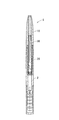
本発明の化粧材のカートリッジは、先筒10と基筒20、及び芯チャック部材30の3部材で構成され、容器本体2に装填されたとき、基筒20は容器本体と同期に回動する手段をとられ、カートリッジ1の摘み部aと容器本体2の相互回動でカートリッジ1内の棒状化粧材が進退する。
The decorative material cartridge of the present invention is composed of three members: a
本発明を添付図面により詳細に説明する。
図1〜5は、第1の実施の形態を示す第1実施例であり、図1はカートリッジ1の縦一部断面図であり、図2は、カートリッジ1の各部材、先筒10,基筒20,芯チャック部材30の各縦一部断面部で、特徴のある部位には先筒10には10桁の、基筒20には20桁の数字が示されている。図3はカートリッジ1を収容する容器本体2を示す縦一部断面図で、第4はカートリッジ1を容器本体2に装填した状態を示し、図5はカートリッジ1の摘み部aと容器本体2を回転操作して芯チャック部材30は繰上前進限に至った状態を示した図である。
The present invention will be described in detail with reference to the accompanying drawings.
FIGS. 1 to 5 show a first example of the first embodiment. FIG. 1 is a longitudinal sectional view of the
図2より各部材の特徴ある部位を説明する。
先筒10は、棒状化粧材Aが進退可能な寸法で穿設された先端開口孔11を備え、この先端開口孔11はほぼ同寸法で貫通孔13として形成される。
The characteristic site | part of each member is demonstrated from FIG.
The
又、この貫通孔13に沿って十字に摺動溝12が設けられ、先筒10の後部内径は腔部14として形成されて、ここには基筒20を回動可能に連結する嵌合凹部15が設けられている。
Further, a
基筒20は有底部25を有する円筒体として形成され、軸方向に上部開口部21側より先筒嵌入部c、容器本体嵌入部bに区分され、先筒嵌入部cは、先筒10との嵌合に使用される先筒嵌合部26が突設され、容器本体嵌入部bには容器本体2の嵌合凹部42と着脱自在に嵌合する嵌合凸部27が突設される。
The
又、実施例では先筒10と基筒20との回動を円滑にするためにOリング20aが、又容器本体2と基筒20との間に生じるガタを防止するためのOリング20bが、基筒20の外周に巻装されている。
In the embodiment, an O-
基筒20内径には上部開口部21より有底部25にいたる軸方向に連続した凹凸でローレット状螺旋23が螺旋部22として形成される。
On the inner diameter of the
さらに、基筒20の外周後部には、係合リブ24が設置され、容器本体2に嵌着した際容器本体2とスプライン係合で基筒20が同期に回動する。
Further, an
実施例では基筒20の外周に設置した係合リブ24によって容器本体2と同期に回動する手段としている。
In the embodiment, the
芯チャック部材30は、先端に棒状化粧材保持部31として爪片32を4片備え、この爪片32に延設される棒軸34は凸条33を含む十字状に形成され、後部には円筒部35が形成される。この円筒部35は前端が繰上当接部38として形成され、外周軸方向にスリット35aが配されるとともに、後端のスリット35bによって形成された凸片37表面に係合突起36が4個突設される。この係合突起は1個でもよいが、安全のために複数片設けた方がよい。
The
上記各部材より構成される図1のカートリッジ1は、先筒10の全長18は、摘み部a、基筒20の容器本体嵌入部bで全姿が形成され、内蔵される芯チャック部材30は棒状化粧材Aの尾部を爪片32で保持し、この爪片32は、先筒10内の摺動溝12内に位置している。
The
前記爪片32より延設される棒軸34の凸条33は、それぞれの摺動溝12に係合して回転止め機構を構成し、芯チャック部材30後部に突設された係合突起36は、基筒20内の連続した凹凸より形成されるローレット状螺旋23に弾性的に螺合して繰出機構を構成する。
The
基筒20の外形寸法は、先筒10の端面16外形寸法より小径な円筒体で形成され、容器本体嵌入部bとして先筒10に連結され、この容器本体嵌入部b外周に容器本体との着脱に使用される嵌合凸部27が設置されている。
The outer dimension of the
図2の(C)図に見られる如く、凸条33の外形寸法をもって前記円筒部35の外径とすればよく、この円筒部35より突設される係合突起36は、(E)図のローレット状螺旋23の谷部に螺合するため、基筒20は内径に螺旋部22が形成されているにもかかわらず、基筒20外径を小径とすることが可能なので、図3に示す容器本体2の外径をも小径とすることが可能となり、結局小径でスマートな、図4に示すカートリッジ式棒状化粧材繰出容器5となる。
As shown in FIG. 2C, the outer diameter of the
図3は、図1のカートリッジ1を収容する容器本体2を示す図で、容器本体2は、カートリッジ1を挿入可能な前部開口孔41を備えた円筒体で形成された外筒40と、この外筒40の後部の小径部40aに固着されたマスカラ刷毛4を保護するキャップ3とで構成される。
FIG. 3 is a diagram showing a container
図4は、カートリッジ1を容器本体2に嵌着した状態を示す図で、カートリッジ1の容器本体嵌入部bは、容器本体2の前部開口孔41より挿入され、腔部43に収容され、嵌合凹部42と容器本体嵌入部bに突設された嵌合凸部27との嵌合によって、容器本体2に確実に連結される。この際、係合リブ24と、容器本体2内のスプライン係合部44がスプライン係合することで、基筒20は容器本体2と同期に回動する。
FIG. 4 is a diagram showing a state in which the
カートリッジ1の摘み部aと容器本体2とを回動すると、容器本体2は、カートリッジ1の基筒20とスプライン係合しているので結局先筒10と基筒20の回動が行われ、前記説明した繰出機構で、棒状化粧材Aは先筒10の先端開口孔11より進出して化粧を施すことが可能となる。又逆に回動すれば、棒状化粧材Aは、先筒10内に収容される。
When the knob part a of the
化粧を施す際に、棒状化粧材Aは、芯チャック部材30のスリット35aの影響で、弾力を持って肌に当接する。
When applying makeup, the rod-shaped decorative material A comes into contact with the skin with elasticity under the influence of the slits 35 a of the
図5は芯チャック部材30を繰上前進限まで繰り出した状態を示すもので、芯チャック部材30後部の円筒部35前端の繰上当接部38は、先筒10の腔部14前端の当接段部17に当接して、繰上前進限が決定される。
FIG. 5 shows a state in which the
この際、爪片32の先端は、摺動溝12の先端の下向き段部に当接しない設定となっているため、繰上前進限で爪片32には負荷がかからない設計となっているので、あらゆるテクスチャーの棒状化粧材に適用しうる化粧材容器のカートリッジ1となっている。
At this time, since the tip of the
さらに、この前進限で、摘み部aと容器本体2の回動負荷がかかると、芯チャック部材30円筒部35に弾性を有して突設された係合突起36は、連続した凹凸で形成された基筒20内のローレット状螺旋23に対して、簡単に螺合離脱を繰り返し、この際カチカチと発生音を立てて使用者に繰り出しの前進限を知らせる。逆に回動すれば係合突起36は簡単に螺合復帰して、棒状化粧材Aを先筒10内に収容する。
Furthermore, when the knob part a and the
又、繰り出しの後退限で同様な更なる芯チャック部材30を後退させる回動負荷がかかった場合も、繰り出し前進限と同様に螺合離脱を繰り返し、発生音をたてて使用者に知らせる。
Also, when a similar turning load is applied to retract the same
なお実施例においては、円筒部35に鍵状スリット35aが軸方向に設置されている。これは、化粧時の棒状化粧材Aの軸方向の弾性を与えるとともに、後退限における芯チャック部材30のクラッチ時の反動を少なくして爪片32に対する振動をより少なくするためになされたものである。
In the embodiment, the
後退限でのクラッチ回転は、前進限のクラッチ回転とは異なり、クラッチの振動が棒状化粧材を爪片32より押し出す方向に力が加わるのを防ぐために、鍵状スリット35aが設置されている。
The clutch rotation at the backward limit is different from the clutch rotation at the forward limit, and a key-like slit 35a is provided in order to prevent the vibration of the clutch from applying a force in the direction in which the stick-shaped decorative material is pushed out from the
本発明は、化粧材容器のカートリッジ1に関する発明であり、先筒10と基筒20と芯チャック部材30とで構成され、基筒20が小径な円筒体として回動可能に先筒10に連結され、カートリッジ1の全姿を形成しているとともに、基筒20内に軸方向に螺旋部22が連続した凹凸で形成されるローレット状螺旋23で形成され、芯チャック部材30が前記ローレット状螺旋23に対して弾性を有して螺合しているので、螺合離脱と螺合復帰をしやすいのを利用して、棒状化粧材と繰出機構の保護を行っていることを特徴としている。
The present invention is an invention relating to a
第1実施例においては、芯チャック部材30の係合突起36は、スリット35bに寄って形成された凸片37に円周上に突設されたが、これに限定されるものではなく、軸方向に多数突設しても、本発明の技術範疇に属するものである。
In the first embodiment, the engaging
図6〜図8は、第2の実施の形態を示す図であり、図6は化粧材容器のカートリッジ101の縦一部断面図を示し、図7はカートリッジ101の各部材、先筒110,基筒120,芯チャック部材130の各部位を示したもので、図8は図3に示す容器本体2にカートリッジ101を装填し、繰上の前進限まで棒状化粧材Bを繰り上げた状態を示す図である。
FIGS. 6 to 8 are views showing a second embodiment. FIG. 6 is a longitudinal sectional view of a
第2実施例も第1実施例同様、図7に示す如く先筒110と基筒120と芯チャック部材130とで構成され、第1実施例と同様に先筒110は先端開口孔111を備え、貫通孔113が穿設され、この貫通孔113に沿って摺動溝112が形成され、芯チャック部材130先端の爪片132は前記摺動溝112に位置して棒状化粧材をを保持摺動し、この爪片132より延設される棒軸134は、十字形摺動溝112に係合して回転止め機構を構成している。又、棒軸134腔部には円筒部135が設けられ、この円筒部135に螺条スリット135aが設けられるとともに、外周に係合突起136が突設され、後述する基筒120の螺旋部に螺合して繰出機構を構成している。
Similarly to the first embodiment, the second embodiment includes a
基筒120は、第1実施例と同様な外径と形状をしており、内部のローレット状螺旋123が内径の約2/3の螺旋切り始めの螺旋部上端部122aより底面まで螺旋部122がストローク長形成されている。
The
第2実施例の特徴は、繰上前進限における回動負荷におけるクラッチ回転にあり、図8に示される。 A feature of the second embodiment resides in clutch rotation at a rotational load in the forward advance limit, and is shown in FIG.
図6に示される摘み部a’と容器本体嵌入部b’より全姿が形成されるカートリッジは、図3に示される容器本体3に装填されると、摘み部a’と容器本体2との回動によって基筒120の係合リブ124によって容器本体2と基筒120は同期に回転し、先筒110と基筒120の回動によって繰出機構が作動し、棒状化粧材Bは先筒110の先端開口孔111より進出し、化粧を可能とする。化粧を施す際、芯チャック部材130の円筒部135に形成した螺条スリット135aによって軸方向に弾性をもって棒状化粧材Bが使用者の肌に当接するため、ソフトなタッチでの化粧を可能とする。
When the cartridge formed entirely from the knob part a ′ and the container main body insertion part b ′ shown in FIG. 6 is loaded into the container
又、図8に示す繰上前進限でさらに回動する負荷がかかると、芯チャック部材130の円筒部135前面の繰上当接部138は、先筒110内の当接段部117に当接しているので、螺条スリット135aは軸方向に縮小し、係合突起下端部136aが螺旋部上端部122aを抜け出し、ローレット状螺旋123の谷部と山部を、螺条スリット135aの軸方向の弾性で、抜け出しによる螺合離脱と螺合復帰を繰り返し、このときカチカチと音を立てて使用者に繰り出しの前進限を知らせる。
Further, when a further rotating load is applied at the advance advance limit shown in FIG. 8, the
第1実施例では、芯チャック部材30の円筒部35に鍵状スリット35aを設け、軸方向の弾性を持たせるとともに、スリット35bによって凸片37の表面に係合突起36を突設したことによって、基筒20内の連続した凹凸より形成されるローレット状螺旋に弾性を有して螺合させ、凸片37の弾性で螺合離脱と螺合復帰をしやすくしたのに対し、第2実施例では、芯チャック部材130の円筒部135に螺条スリット135aを設け、軸方向の弾性を持たせ、基筒120内径に螺旋部上端部122aの螺旋切り始めを有する螺旋部122を軸方向に設置し、前記芯チャック部材130の円筒部135後部に係合突起136を突設して前記螺旋部122に螺合させるとともに、繰上前進限で円筒部135を螺条スリット135aによる縮小で係合突起136を螺旋部122より抜け出させ、円筒部135の螺条スリット135aの復元力で前記係合突起136が又螺旋部122に螺合する手段をとったもので、第1実施例、第2実施例とも基筒20,120内の連続した凹凸より形成されるローレット状螺旋23,123で螺旋部22,122を形成した事を特徴とし、芯チャック部材30,130後部の係合突起36,136に螺合している。
In the first embodiment, the
さらには、芯チャック部材30,130には、後部には円筒部35,135が設けられ、この円筒部には鍵状スリット35aや螺条スリット135aが設けられ、円筒部35,135が軸方向に弾性を有する手段がとられる。
Further, the
図9〜図10は、第3の実施の形態を示す、化粧材容器のカートリッジ201を開示したもので、図9はカートリッジ201の縦一部断面図を示し、図10は使用される部位を示している。
9 to 10 show a
カートリッジ201は、第1実施例のカートリッジ1と同様な繰出機構と作動をするものであるが、棒状化粧材Cが楕円形状に形成されているため、図10で示す(A’)図の先筒210は、先端開口孔211が前記楕円芯の棒状化粧材Cが摺動可能な相似楕円先端開口孔211として配され、(B’)図に見られる如く摺動溝212は貫通孔213の長軸に沿って短軸に対峙して一対もうけられていることを特徴としている。
The
一対の爪片232によって棒状化粧材保持部231を構成し、(C’)図に示すように凸条233も一対の凸条として摺動溝212に係合して回転止め機構を構成する。
A pair of
カートリッジ201が図3の容器本体2に装填され、摘み部aと容器本体2との回転操作によって第1実施例と同様な繰出機構によって棒状化粧材Cは先筒210の先端開口孔211より進出する。化粧を施す際には、芯チャック部材230の円筒部235に設けた鍵状スリット235aの軸方向の弾性によって、ソフトなタッチで化粧を施すことが可能である。
The
又、繰上前進限後退限の回動負荷には、係合突起236が基筒220内の螺旋部に対し、螺合離脱と螺合復帰を繰り返すことでカチカチと音を立て、使用者にこれを知らせるとともに、繰出機構と棒状化粧材Cの安全性を保証する。
In addition, for the rotational load at the forward advance limit / retreat limit, the
本発明は、化粧材容器のカートリッジに関する発明であり、先筒と基筒を先筒端面の外径より小径な円筒体として回動可能に連結し、基筒内に連続した凹凸により形成されるローレット状螺旋を螺旋部として軸方向にストローク長設け、芯チャック部材の後部に突設した係合突起によって繰出機構を構成することで、安全性が高く、最少の部品点数で構成されるとともに、外径が小径なカートリッジを提供可能とした発明である。
The present invention relates to a cartridge for a decorative material container, and is formed by continuous concavities and convexities in a base cylinder by connecting the front cylinder and the base cylinder as a cylindrical body having a smaller diameter than the outer diameter of the front end face. By providing a stroke length in the axial direction with a knurled spiral as a spiral part and configuring a feeding mechanism with an engagement projection protruding from the rear part of the core chuck member, the safety is high, and it is configured with a minimum number of parts, This invention makes it possible to provide a cartridge having a small outer diameter.
1・・・・カートリッジ
2・・・・容器本体
3・・・・キャップ
4・・・・マスカラ刷毛
5・・・・カートリッジ式棒状化粧材繰出容器
A・・・・棒状化粧材
a・・・・摘み部
b・・・・容器本体嵌入部
c・・・・先筒嵌入部
10・・・先筒
11・・・先端開口孔
12・・・摺動溝
13・・・貫通孔
14・・・腔部
15・・・嵌合凹部
16・・・端面
20・・・基筒
20a・・Oリング
20b・・Oリング
21・・・上部開口部
22・・・螺旋部
23・・・ローレット状螺旋
24・・・係合リブ
25・・・有底部
26・・・先筒嵌合部
27・・・嵌合凸部
30・・・芯チャック部材
31・・・棒状化粧材保持部
32・・・爪片
33・・・凸条
34・・・棒軸
35・・・円筒部
35a・・スリット
35b・・スリット
36・・・係合突起
37・・・凸片
38・・・繰上当接部
101・・カートリッジ
B・・・・棒状化粧材
110・・先筒
111・・先端開口孔
112・・摺動溝
113・・貫通孔
117・・当接段部
120・・基筒
122・・螺旋部
122a・螺旋部上端部
123・・ローレット状螺旋
124・・係合リブ
130・・芯チャック部材
132・・爪片
134・・棒軸
135・・円筒部
135a・螺条スリット
136・・係合突起
136a・係合突起下端部
138・・繰上当接部
201・・カートリッジ
C・・・・棒状化粧材
210・・先筒
211・・先端開口孔
212・・摺動溝
213・・貫通孔
220・・基筒
230・・芯チャック部材
231・・棒状化粧材保持部
232・・爪片
233・・凸条
235・・円筒部
235a・鍵状スリット
236・・係合突起
DESCRIPTION OF
Claims (4)
棒状化粧材を保持する複数の爪片を先端に備え、この爪片を前記複数の摺動溝に位置させ、前記先筒と同期に回動する手段をとられた芯チャック部材と、
前記先筒に回動可能に連結される基筒より構成される化粧材容器のカートリッジであって;
前記基筒の容器本体嵌入部には、容器に嵌着したときに容器本体と同期に回動する手段が取られるとともに前記基筒の内径にはローレット状螺旋が螺旋部としてストローク長形成され、前記芯チャック部材の後部に突設された係合突起が前記螺旋部に螺合して繰出機構を構成し、
前記芯チャック部材の棒軸後部には、鍵状スリット又は螺条スリットが形成され、前記鍵状スリット又は前記螺条スリットが軸方向に縮小することによって軸方向に弾性を有して伸縮する円筒部が設けられ、この円筒部の外周より係合突起を突設し、この係合突起が弾性的に前記基筒のローレット状螺旋に螺合していることを特徴とする化粧材容器のカートリッジ。 A front tube having an opening hole through which the rod-shaped decorative material advances and retreats, having a through hole with substantially the same size as the opening hole, and forming a plurality of sliding grooves along the through hole;
A core chuck member provided with a plurality of claw pieces for holding a stick-shaped decorative material at the tip, and positioning the claw pieces in the plurality of sliding grooves, and means for rotating in synchronization with the tip tube;
A cosmetic container cartridge comprising a base cylinder rotatably connected to the leading cylinder;
The container main body insertion portion of the base tube is provided with means for rotating in synchronism with the container main body when fitted to the container, and the inner diameter of the base tube is formed with a knurled spiral as a spiral length, The engaging protrusion projecting from the rear part of the core chuck member is screwed into the spiral part to constitute a feeding mechanism,
The rod shaft rear portion of the core chuck member, hooked slits or screw thread slits are formed, the key-shaped slit or the screw threads slits stretch has elasticity in the axial direction by Rukoto be reduced in the axial direction A cosmetic container characterized in that a cylindrical portion is provided, and an engaging projection protrudes from the outer periphery of the cylindrical portion, and the engaging projection is elastically screwed into the knurled spiral of the base tube. cartridge.
Priority Applications (1)
| Application Number | Priority Date | Filing Date | Title |
|---|---|---|---|
| JP2004142480A JP4708730B2 (en) | 2004-05-12 | 2004-05-12 | Cosmetic container cartridge |
Applications Claiming Priority (1)
| Application Number | Priority Date | Filing Date | Title |
|---|---|---|---|
| JP2004142480A JP4708730B2 (en) | 2004-05-12 | 2004-05-12 | Cosmetic container cartridge |
Publications (3)
| Publication Number | Publication Date |
|---|---|
| JP2005323675A JP2005323675A (en) | 2005-11-24 |
| JP2005323675A5 JP2005323675A5 (en) | 2007-06-21 |
| JP4708730B2 true JP4708730B2 (en) | 2011-06-22 |
Family
ID=35470495
Family Applications (1)
| Application Number | Title | Priority Date | Filing Date |
|---|---|---|---|
| JP2004142480A Active JP4708730B2 (en) | 2004-05-12 | 2004-05-12 | Cosmetic container cartridge |
Country Status (1)
| Country | Link |
|---|---|
| JP (1) | JP4708730B2 (en) |
Families Citing this family (4)
| Publication number | Priority date | Publication date | Assignee | Title |
|---|---|---|---|---|
| WO2008045786A2 (en) * | 2006-10-06 | 2008-04-17 | Cosmolab Inc. | Mechanical pencil |
| JP2009000339A (en) * | 2007-06-22 | 2009-01-08 | Suzuno Kasei Kk | Cartridge of cosmetic container |
| JP4663032B1 (en) * | 2010-09-22 | 2011-03-30 | 鈴野化成株式会社 | Stick-shaped cosmetic material feeding container |
| JP2013111377A (en) * | 2011-11-30 | 2013-06-10 | Suzuno Kasei Kk | Cartridge for stick cosmetic material delivery container |
Citations (3)
| Publication number | Priority date | Publication date | Assignee | Title |
|---|---|---|---|---|
| JP2002191431A (en) * | 1995-02-02 | 2002-07-09 | Suzuno Kasei Kk | Screw-out container for stick-shaped cosmetic material |
| JP2003159119A (en) * | 2001-11-27 | 2003-06-03 | Suzuno Kasei Kk | Rod-shaped cosmetic screw-out container |
| JP2004097549A (en) * | 2002-09-10 | 2004-04-02 | Tokiwa Corp | Cosmetic delivery container and method for assembling the same |
-
2004
- 2004-05-12 JP JP2004142480A patent/JP4708730B2/en active Active
Patent Citations (3)
| Publication number | Priority date | Publication date | Assignee | Title |
|---|---|---|---|---|
| JP2002191431A (en) * | 1995-02-02 | 2002-07-09 | Suzuno Kasei Kk | Screw-out container for stick-shaped cosmetic material |
| JP2003159119A (en) * | 2001-11-27 | 2003-06-03 | Suzuno Kasei Kk | Rod-shaped cosmetic screw-out container |
| JP2004097549A (en) * | 2002-09-10 | 2004-04-02 | Tokiwa Corp | Cosmetic delivery container and method for assembling the same |
Also Published As
| Publication number | Publication date |
|---|---|
| JP2005323675A (en) | 2005-11-24 |
Similar Documents
| Publication | Publication Date | Title |
|---|---|---|
| JP4355753B1 (en) | Coating material extrusion container | |
| JP2009285082A (en) | Application material extrusion container | |
| JP6281068B2 (en) | Stick-shaped cosmetic supply container | |
| JP5066201B2 (en) | Stick-shaped cosmetic supply container | |
| JP6191970B2 (en) | Feeding pencil | |
| JP3636629B2 (en) | Cartridge type feeding container | |
| JP5374342B2 (en) | Coating material extrusion container | |
| JP4708730B2 (en) | Cosmetic container cartridge | |
| JP4921277B2 (en) | Coating material extrusion container | |
| JP2989503B2 (en) | Stick-shaped cosmetic material feeding container | |
| JP5035793B2 (en) | Stick-shaped cosmetic container | |
| JP5133749B2 (en) | Mobile feeding container | |
| JP2003159119A (en) | Rod-shaped cosmetic screw-out container | |
| JP4627433B2 (en) | Mobile feeding container | |
| JP2004181001A (en) | Stick-shaped cosmetic material feeding container | |
| JP7145036B2 (en) | Rod-shaped core feeding tool | |
| JP4212843B2 (en) | Cartridge-type stick-shaped cosmetic material feeding container | |
| JP6262466B2 (en) | Solid bar cosmetic container | |
| JP4741176B2 (en) | Stick-shaped cosmetic material feeding container | |
| JP4111741B2 (en) | Stick-shaped cosmetic container | |
| JP2002300917A (en) | Cartridge type cosmetic container | |
| JP4331935B2 (en) | Stick-shaped cosmetic supply container | |
| JP2003339438A (en) | Stick-like cosmetic material delivery case | |
| JP4352061B2 (en) | Stick-shaped cosmetic supply container | |
| JP2001286337A (en) | Screw-out case for bar cosmetic |
Legal Events
| Date | Code | Title | Description |
|---|---|---|---|
| A521 | Request for written amendment filed |
Free format text: JAPANESE INTERMEDIATE CODE: A523 Effective date: 20070427 |
|
| A621 | Written request for application examination |
Free format text: JAPANESE INTERMEDIATE CODE: A621 Effective date: 20070427 |
|
| A977 | Report on retrieval |
Free format text: JAPANESE INTERMEDIATE CODE: A971007 Effective date: 20100903 |
|
| A131 | Notification of reasons for refusal |
Free format text: JAPANESE INTERMEDIATE CODE: A131 Effective date: 20100921 |
|
| RD03 | Notification of appointment of power of attorney |
Free format text: JAPANESE INTERMEDIATE CODE: A7423 Effective date: 20101007 |
|
| A521 | Request for written amendment filed |
Free format text: JAPANESE INTERMEDIATE CODE: A523 Effective date: 20101112 |
|
| A131 | Notification of reasons for refusal |
Free format text: JAPANESE INTERMEDIATE CODE: A131 Effective date: 20101221 |
|
| A521 | Request for written amendment filed |
Free format text: JAPANESE INTERMEDIATE CODE: A523 Effective date: 20110131 |
|
| TRDD | Decision of grant or rejection written | ||
| A01 | Written decision to grant a patent or to grant a registration (utility model) |
Free format text: JAPANESE INTERMEDIATE CODE: A01 Effective date: 20110222 |
|
| A61 | First payment of annual fees (during grant procedure) |
Free format text: JAPANESE INTERMEDIATE CODE: A61 Effective date: 20110317 |
|
| R150 | Certificate of patent or registration of utility model |
Ref document number: 4708730 Country of ref document: JP Free format text: JAPANESE INTERMEDIATE CODE: R150 |
|
| R250 | Receipt of annual fees |
Free format text: JAPANESE INTERMEDIATE CODE: R250 |
|
| R250 | Receipt of annual fees |
Free format text: JAPANESE INTERMEDIATE CODE: R250 |
|
| R250 | Receipt of annual fees |
Free format text: JAPANESE INTERMEDIATE CODE: R250 |
|
| R250 | Receipt of annual fees |
Free format text: JAPANESE INTERMEDIATE CODE: R250 |
|
| R250 | Receipt of annual fees |
Free format text: JAPANESE INTERMEDIATE CODE: R250 |
|
| R250 | Receipt of annual fees |
Free format text: JAPANESE INTERMEDIATE CODE: R250 |
|
| R250 | Receipt of annual fees |
Free format text: JAPANESE INTERMEDIATE CODE: R250 |
|
| R250 | Receipt of annual fees |
Free format text: JAPANESE INTERMEDIATE CODE: R250 |
|
| R250 | Receipt of annual fees |
Free format text: JAPANESE INTERMEDIATE CODE: R250 |
|
| R250 | Receipt of annual fees |
Free format text: JAPANESE INTERMEDIATE CODE: R250 |