JP4708601B2 - Strip rubber member cutting method and cutting apparatus - Google Patents
Strip rubber member cutting method and cutting apparatus Download PDFInfo
- Publication number
- JP4708601B2 JP4708601B2 JP2001153695A JP2001153695A JP4708601B2 JP 4708601 B2 JP4708601 B2 JP 4708601B2 JP 2001153695 A JP2001153695 A JP 2001153695A JP 2001153695 A JP2001153695 A JP 2001153695A JP 4708601 B2 JP4708601 B2 JP 4708601B2
- Authority
- JP
- Japan
- Prior art keywords
- cutter
- rubber member
- belt
- cutting
- speed
- Prior art date
- Legal status (The legal status is an assumption and is not a legal conclusion. Google has not performed a legal analysis and makes no representation as to the accuracy of the status listed.)
- Expired - Fee Related
Links
Images


Description
【0001】
【発明の属する技術分野】
本発明は、帯状ゴム部材切断方法及び切断装置に関する。
【0002】
【従来の技術】
従来、図7に示すように、ベルトコンベヤー43上を送られてくる連続帯状ゴム部材42に於て、設定された長さだけ帯状ゴム部材42が送られ、コンベヤー43を一旦停止させて、コンベヤー43上を帯状ゴム部材42の幅方向に横行移動する回転式カッター44により、帯状ゴム部材42を幅方向に切断をする方法・装置が用いられている。又は、コンベヤーを運転したまま、つまり、ベルトコンベヤー上を連続的に送られてくる帯状ゴム部材に於ては、帯状ゴム部材を設定した長さだけ送られた後、カッターを備える台車がコンベヤーの進行方向に同じ速度で走行し、運転中のコンベヤー上を帯状ゴム部材の幅方向に横行移動する回転式カッターにより、帯状ゴム部材を幅方向に切断をする方法・装置が用いられている。
【0003】
上記図7に示す間欠的に送られる帯状ゴム部材42を切断する方法・装置、又は、帯状ゴム部材を連続的に送りながら切断する方法・装置に於ては共に、図8に示すカッターの動きの説明図に示すように制御される。カッターによる帯状ゴム部材を切断後(切断工程C完了後)カッターの横行速度(図8の上部グラフ)がVから0となった後(点x)、カッターの上下位置(図8の下部グラフ)は、カッターを切断可能高さの下方位置Lから待機位置への返還移動可能高さの上方位置Uまで上昇させ(点y)、その後、カッターを横行速度Vにより待機位置45(図7参照)まで移動させる(戻り工程B)。そして、カッターを待機位置45に到達させてから後(点z)、カッターを上方位置Uから下方位置Lに降下させ、停止させる(以上で1サイクル)。そして、帯状ゴム部材2を必要長さだけ送り、カッターを帯状ゴム部材の幅方向に横行移動させ、再度切断を行う(切断工程C)ものである。
【0004】
【発明が解決しようとする課題】
図8に示すように、切断工程C、カッター上昇、戻り工程B、カッター降下の一連の動作は、夫々の動作(工程)が完了確認後、次の動作に移るという動作時間が積み上げ式となる制御方法・装置であるため、切断動作開始から、待機位置にカッターが戻るまでに時間を要し、そのため、コンベヤーの送り時間が制限され単位時間当たりの切断作業能率が好ましくないという問題がある。
【0005】
そこで本発明は、切断サイクルの時間短縮が可能で、且つ、良好な切断面を有することができる帯状ゴム部材切断方法及び切断装置を提供することを目的とする。
【0006】
【課題を解決するための手段】
上述の目的を達成するために、本発明に係る帯状ゴム部材切断方法は、カッターが待機位置から、連続的に送られてくる帯状ゴム部材の送り速度と同じ速度で前進移動しながら、該帯状ゴム部材の幅方向に横行移動しつつ該帯状ゴム部材を幅方向に切断する方法であって、上記カッターが、切断面両端部に薄肉部を有し且つ中間部に肉厚部を有するタイヤ用の帯状ゴム部材を幅方向に切断する際、切断開始時には、該帯状ゴム部材の上記薄肉部が変位乃至変形を伴わないよう低速で、その後、該帯状ゴム部材の上記中間部以後は、良好な切断面を有することができる程度の高速に、上記カッターが移動速度を変更して横行移動しながら該帯状ゴム部材の切断を行って、該帯状ゴム部材の切断後上記カッターが横行移動停止する前に、該カッターが横行速度を減速しつつ該帯状ゴム部材から離れた上方位置に移動し、該カッターが上記待機位置に戻って停止する前に、該カッターが横行速度を減速しつつ上記帯状ゴム部材を切断できる下方位置まで移動するものである。
【0007】
上述の目的を達成するために、本発明に係る帯状ゴム部材切断装置は、横断面両端部に薄肉部を有し且つ中間部に肉厚部を有するタイヤ用の帯状ゴム部材を搬送装置により連続的に送りながら幅方向に切断するカッターを備える帯状ゴム部材切断装置であって、該カッターを有するカッターキャリッジと、該カッターと該カッターキャリッジを上記帯状ゴム部材の幅方向に横行移動させる横行機構と、上記カッターを昇降させる昇降駆動機構と、該カッターキャリッジと該横行機構と該昇降駆動機構とを有するカッター台車と、該カッター台車を上記帯状ゴム部材の送り方向に移動させる同期送り機構と、上記昇降駆動機構と上記横行機構と上記同期送り機構とを制御する制御手段と、を有し、制御手段によって、上記カッターが上記待機位置から、連続的に送られてくる上記帯状ゴム部材の送り速度と同じ速度で前進移動しながら、該帯状ゴム部材の幅方向に横行移動しつつ該帯状ゴム部材を幅方向に切断するように制御し、かつ、該帯状ゴム部材の切断後上記カッターが上記横行移動を停止する前に該カッターが減速すると共に上昇させ、かつ、所定待機位置に戻って停止する前に上記カッターが減速すると共に下降させるように制御し、さらに、上記カッターは、上記帯状ゴム部材の一端の薄肉部が変位乃至変形を伴わないよう低速で切断を開始し、該帯状ゴム部材の中間肉厚部から他端の薄肉部まで良好な切断面を有することができる程度の高速で切り抜けるように、上記横行機構が、上記カッターの移動速度を変更して横行移動させながら該帯状ゴム部材を幅方向に切断するように構成したものである。
【0008】
【発明の実施の形態】
以下、図示の実施の形態に基づき、本発明を詳説する。
【0009】
本発明による帯状ゴム部材切断装置は、ベルトコンベヤー等の搬送装置10により(連続的又は間欠的に)押出機(図示省略)から押し出され、送られる、ゴムタイヤを構成するトレッド等の帯状ゴム部材2を順次、タイヤ1本相当分の所定長さ寸法に切断する装置である。
【0010】
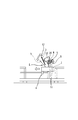
図1及び図2は、帯状ゴム部材切断装置の実施の一形態を示す平面図及び側面図であり、図1の平面図において、回転式の円板状のカッター3は、帯状ゴム部材2を幅方向に切断する切断刃であり、このカッター3は、待機位置7(2点鎖線の状態)から、連続的に送られてくる帯状ゴム部材2の送り速度と同じ速度で前進移動しながら(相対速度を0として)、帯状ゴム部材2の幅方向に横行移動(左右方向移動)しつつ帯状ゴム部材2を幅方向に切断するものである(切断工程C)。そして、切断完了後、カッター3は待機位置7へ戻って待機状態となる(戻り工程B)ものであり(以上で1サイクル)、待機状態から引き続いて、カッター3は待機位置7から切断を開始するものである。
【0011】
連続的に送られてくる帯状ゴム部材2の送り速度と同じ速度で前進移動しながら、帯状ゴム部材2の幅方向に横行移動しつつ帯状ゴム部材2を幅方向に切断するカッター3の動きは、図1に示す矢印のように、帯状ゴム部材2上を斜行運動するものである。
【0012】
帯状ゴム部材2の切断時は、図2に示すように、搬送装置10上の帯状ゴム部材2を切断する為に、カッター3は、切断可能な切断高さの下方位置Lに配置され、切断を行うものである。そして、切断完了後、カッター3は、帯状ゴム部材2の上方を横切るよう通過して待機位置7へ戻るために、下方位置Lから、待機位置7への移動可能高さの上方位置Uまで上昇し(図3参照)移動を行うものである。
【0013】
また、円板状のカッター3は、図2に示すように側面視に於いて、右下がりに配置(進行方向に前傾)されるため、帯状ゴム部材2の切断面形状は、そのカッター3の配置角度に対応した、右下がりの(帯状ゴム部材2の長手面に対して傾斜した)前傾斜面を有する切断面を得る。これにより、帯状ゴム部材2の加工次工程で行われる両端切断面の接着は、接着面拡大等の作用により良好なものとすることができ、タイヤとしての性能も、接合部は非接合部と同様のものとすることができる。また、カッター3切断位置は、搬送装置10の搬送ベルト材等は下方へ控えて、帯状ゴム部材2のみを切断するよう構成されている。
【0014】
次にカッター3の昇降運転について、さらに詳説すると、カッター3は、帯状ゴム部材2の切断後、上記の横行移動停止をする前に、カッター3が帯状ゴム部材2から離れた上方位置Uに移動し、カッター3が待機位置7に戻って停止する前に、カッター3が帯状ゴム部材2を切断できる下方位置Lまで移動するものである。即ち、カッター3の昇降運転は、切断工程C及び戻り工程B内に含まれる同時運転するものであり、カッター3の動きは、1軸のみ(横行運動)の運転だけでなく、2軸の運転(横行運動及び昇降運動)を同時に有する立体3次元運動をおこなうよう制御されている。
【0015】
さらに帯状ゴム部材切断装置について、具体的に説明すると、所定待機位置7(図1)から帯状ゴム部材2を幅方向に切断する回転式のカッター3は、図3に示すように、カッターキャリッジ8に取着されており、図1に示すように、カッターキャリッジ8は、帯状ゴム部材2の幅方向に横行移動させる横行機構5に走行可能に支持されている。
【0016】
横行機構5は、帯状ゴム部材2の幅方向に設けた2本のガイドレール11と、ガイドレール11に平行でそれら間に位置する雄ネジ杆12と、雄ネジ杆12を回転させる横行用サーボモータ13とを有する。そして、カッターキャリッジ8は、このガイドレール11に嵌合する(図示省略の)ローラを有し、雄ネジ杆12に螺合する雌ネジを備えるソケット14を有し、雄ネジ杆12が回転することにより、ソケット14がこの雄ネジ杆12に沿って移動し、カッターキャリッジ8がガイドレール11に沿って走行するものである。また、この雄ネジ杆12及びソケット14の雌ネジは、ボールネジとすることにより動力の伝達効率を上げ、カッター3の横行移動を滑らか且つ高速に行えるものとする。又は、上記横行機構5が備えるカッターキャリッジ8の位置変位機構を、タイミングベルト式にしてもよいものである。
【0017】
次に、カッター3を昇降させる昇降駆動機構6は、上述のとおり、カッター3を上方位置U及び下方位置Lに昇降(揺動)運動させるものであり、図2及び図3に示すように、カッターキャリッジ8(又はカッターキャリッジ8と横行機構5)を昇降(揺動)運動させるものである。又は、図示省略するが、カッター3のみを昇降又は揺動させるものとしてもよい。
【0018】
次に、カッター3を帯状ゴム部材2の送り方向へ移動させる(進退動作)走行手段は、カッターキャリッジ8と横行機構5と昇降駆動機構6と、を搭載したカッター台車1を有するものとする。このカッター台車1は図2に示すように、同期送り機構4により、帯状ゴム部材2の送り方向へ前後方向移動できるものであり、同期送り機構4は、帯状ゴム部材2の長手方向に設けた雄ネジ杆15と、雄ネジ杆15を回転させる送り移動用サーボモータ16と図示省略のガイドレールと、を備える。そして、カッター台車1は、雄ネジ杆15に螺合する雌ネジ部17を有し、雄ネジ杆15が回転することにより、雌ネジ部17がこの雄ネジ杆15に沿って移動し、ガイドレールに沿って、カッター台車1は前後方向走行するものである。また、この雄ネジ杆15及び雌ネジ部17は、上記横行機構5と同様ボールネジとすることで、走行移動を滑らか且つ高速に行えるものとする。又は、昇降駆動機構6が備えるカッター台車1の位置変位機構を、タイミングベルト式にしてもよいものである。
【0019】
そして、昇降駆動機構6と横行機構5と同期送り機構4は、制御手段9により、カッター3が帯状ゴム部材2の切断後停止する前に上記カッター3を上昇させ、且つ、所定待機位置7に戻って停止する前にカッター3を下降させるよう制御した(シーケンスが組まれた)ものである。
【0020】
この制御手段9による、カッター3の運転制御について、さらに以下のように説明する。切断工程Cは、待機位置7にあるカッター3が切断作業開始後(幅方向移動開始後)カッター3が帯状ゴム部材2に接触するまでの第1余裕代ゾーンと、実際切断を行う切断ゾーンと、(帯状ゴム部材2からカッター3が離れる)切断完了後カッター3が横行停止するまでの第2余裕代ゾーンとを有する。そして、制御手段9は、帯状ゴム部材2の切断後、カッター3が下方位置Lから上方位置Uに移動するカッター上昇運動が、上記第2余裕ゾーンに含まれるか又は第2余裕ゾーンと一致するよう設定される。また、カッター3が待機位置7に戻って停止する前のカッター3が上方位置Uから下方位置Lに移動するカッター降下運動が、戻り工程Bの後半乃至戻り工程Bと一致するよう設定されるものである。また、カッター3は切断後及び待機位置7到着後、停止することなく、次の工程へ連続的に移動向きを変えて移動してもよいものである。
【0021】
図5に、上記制御手段9により制御されたカッターの動きを示す。図5の上部グラフはカッター横行速度を示し、下部グラフはカッターの上下位置を示すものである。カッター3の発進指令a後(カッター3は下方位置Lにある)、カッター3の横行移動速度はVに達し切断を行う。その後減速命令bと同時にカッター3の上昇指令mによりカッター3が下方位置Lから上方位置Uまで上昇し、停止して切断工程Cが終了する。続いて、戻り工程Bは、カッター3が上方位置Uのまま、発進指令dにより横行速度V(又は任意の速度)、で待機位置7へ移動始める。そして、横行速度Vで戻るカッター3は減速指令eにより減速を始めるとともにカッター3の降下指令nによりカッター3が上方位置Uから下方位置Lまで降下し、停止して戻り工程Bを終了する。以上を1サイクルとして連続して切断を行うものとする。
【0022】
また、上記カッター3(カッターキャリッジ8)の移動距離及びカッター3の昇降(揺動)距離は制御手段9により、上記指令信号を出力するよう設定されている。又は、カッター3の位置確認は、夫々の動作始端・終端に位置検出用のセンサー等によって行ってもよい。
【0023】
次に、カッター3は、帯状ゴム部材2の幅方向に移動速度を変更して横行移動しながら帯状ゴム部材2を幅方向に切断するようしたものとする。これは、横行機構5が、カッター3を帯状ゴム部材2の幅方向に横行(移動)速度Vを変更させて帯状ゴム部材2を幅方向に切断するよう制御したものである。
【0024】
これは、従来、横行(移動)速度Vを(高速で)一定にして切断を行うと、タイヤを構成する帯状ゴム部材2(トレッド)の厚さが薄いもの、又は、(厚さの薄い)サイドウォール付きの帯状ゴム部材2(トレッド)を、カッター3の回転によって帯状ゴム部材2を切断する際、帯状ゴム部材2の切断面両縁部の薄肉部は剛性が低く、カッター3の切断移動時に適切に切断されないで横行方向(左右方向)に薄肉部が押されて切断面が荒れた状態で切断が行われてしまう。その結果、この帯状ゴム部材2は次工程に於いて、タイヤビルディングマシンで円筒状にロールして端面を接着する際、その両端面がそろわず、均一な接着が得られない。また、その接合部での分離(セパレーション)や、タイヤ回転力のアンバランス等の不具合を引き起こすこととなる。
【0025】
しかし、上記のように横行(移動)速度Vを変更させて切断することでこの不具合は改善できる。図4の(イ)(ロ)に示すように、具体的に説明すると、カッター3が帯状ゴム部材2を幅方向に切断する際、切断開始時(切り込み時)には、帯状ゴム部材2の薄肉部乃至シャープエッジ部が変位乃至変形を伴わないように低速VS で横行移動させて確実な切断を行い(切り込み開始から約100mm 〜200mm )、その後、帯状ゴム部材2の中間部以後は、良好な切断面を有することができる程度の高速VH で切り抜けさせるように、カッター3の移動速度を高速に変更して横行移動させながら帯状ゴム部材2の切断を行うものである。また、上記良好な切断面を有することができる程度とは、その切断両端面を接着する際、その接着性能、又は、タイヤとして構成させたときその接合面による不具合を発生させない状態をいう。
【0026】
次に、上記図5に示したカッター3の制御手段9に、この横行変速機能を加えた制御手段9により制御されたカッターの動きを図6に示す。カッター3の発進指令a後(カッター3は下方位置Lにある)、カッター3の横行移動速度は一旦低速のVS に達し帯状ゴム部材2の薄肉部の切断を行う。そして、カッター3が帯状ゴム部材2の肉厚部付近に達するところで、加速指令fによりカッター3の横行速度をVH まで加速して一定速度VH で切断を継続する。切断後減速命令bと同時にカッター3は下方位置Lから上方位置Uまで上昇し、停止して切断工程Cが終了する。続いて、戻り工程Bは、カッター3が上方位置Uのまま、発進指令dにより横行速度VH (又は任意速度V)で待機位置7へ移動始める。そして、横行速度Vで待機位置7に戻ってカッター3は減速指令eにより減速を始めるとともにカッター3は上方位置Uから下方位置Lまで降下し、停止して戻り工程Bを終了する。以上を1サイクルとして、連続して帯状ゴム部材2の切断を行うものとする。
【0027】
そして、このカッター3の横行変速機能により、良好な切断面を得ることができ、カッター3の昇降動作により、帯状ゴム部材2の送り速度(搬送装置10の送り速度)を上げることができる。そして、この横行変速機構の速度調節及び移動距離は、自由に変更可能なものであり、あらかじめ設定できるものである。
【0028】
【発明の効果】
本発明は上述の構成により次のような効果を奏する。
【0029】
以上のように、帯状ゴム部材切断方法及び切断装置は、カッター3をスムーズかつ効率よく作動させることができる。つまり、帯状ゴム部材2の幅方向切断サイクルの短縮を可能とし、帯状ゴム部材2(搬送装置10)の送り速度の低下若しくは、停止を防ぎ、生産性を向上させることが可能である。
【0030】
さらに、帯状ゴム部材2を長手方向に送りながら幅方向の切断を行うことで、一層ロス時間を短縮し、帯状ゴム部材2の切断サイクルの短縮を可能とすることができ、帯状ゴム部材2(搬送装置10)の送り速度の低下若しくは、停止を防ぎ、生産性を向上させることが可能である。
【0031】
また、帯状ゴム部材2の横断面形状に適応した条件の切断が行え、良好な切断面を得ることが可能であり、タイヤ構成部材としての性能を充分に引き出すことが可能である。
【0032】
また、帯状ゴム部材2特有の横断面形状の切断について、帯状ゴム部材2の切断面の厚さに左右されることなく、薄肉部においても良好な切断面を得ることができる。従って、切断後の帯状ゴム部材2を次工程においてタイヤ構成部材の円筒状としたときに、切断面の接着が確実で、接着部の分離、タイヤ回転力のアンバランス等の問題を引き起こさないようすることができる。
また、帯状ゴム部材2の切り込み時カッター3の横行速度Vを遅くしても、横行機構5による横行移動速度の変更動作により、全体の生産速度を落とすことがなく、且つ、良好な切断面を得ることが可能となる。
【図面の簡単な説明】
【図1】 本発明の帯状ゴム部材切断装置の実施の一形態を示す全体平面図である。
【図2】 本発明の帯状ゴム部材切断装置の実施の一形態を示す側面図である。
【図3】 本発明のカッター揺動手段の一例を示す側面図である。
【図4】 本発明のカッターの切断を説明する帯状ゴム部材の横断面図である。
【図5】 本発明の帯状ゴム部材切断方法に於けるカッターの動きの説明図である。
【図6】 本発明の帯状ゴム部材切断方法に於けるカッターの動きの説明図である。
【図7】 従来の帯状ゴム部材切断装置を示す全体平面図である。
【図8】 従来の帯状ゴム部材切断方法におけるカッターの動きの説明図である。
【符号の説明】
1 カッター台車
2 帯状ゴム部材
3 カッター
4 同期送り機構
5 横行機構
6 昇降駆動機構
7 待機位置
8 カッターキャリッジ
9 制御手段
10 搬送装置
V S 低速
V H 高速 [0001]
BACKGROUND OF THE INVENTION
The present invention relates to a strip rubber member cutting method and a cutting device.
[0002]
[Prior art]
Conventionally, as shown in FIG. 7, in the continuous belt-
[0003]
In both the method and apparatus for cutting the intermittently fed belt-
[0004]
[Problems to be solved by the invention]
As shown in FIG. 8, the series of operations of the cutting process C, the cutter ascending, the returning process B, and the cutter descending is an accumulating operation time in which each operation (process) is confirmed to be completed and then moved to the next operation. Since it is a control method / apparatus, it takes time for the cutter to return to the standby position from the start of the cutting operation. Therefore, there is a problem that the feeding time of the conveyor is limited and the cutting work efficiency per unit time is not preferable.
[0005]
Then, an object of this invention is to provide the strip | belt-shaped rubber member cutting method and cutting apparatus which can shorten the time of a cutting cycle and can have a favorable cut surface.
[0006]
[Means for Solving the Problems]
To achieve the above object, the strip rubber member cutting method according to the present invention, the cutter standby position while moving forward at the same speed as the feed speed of the belt-shaped rubber member sent continuously, the strip A method for cutting a belt-shaped rubber member in a width direction while traversing in the width direction of the rubber member, wherein the cutter has a thin portion at both ends of the cut surface and a thick portion at an intermediate portion. When the band-shaped rubber member is cut in the width direction, at the start of cutting, the thin-walled portion of the band-shaped rubber member is slow so as not to be displaced or deformed. The cutter cuts the belt-like rubber member while traversing and changing the moving speed at such a high speed that it can have a cut surface, and before the cutter stops traversing after cutting the belt-like rubber member to, the cutter There moves upward position away from the belt-shaped rubber member while decelerating the traverse speed, before the cutter stops returns to the standby position, cutting the belt-shaped rubber member with the cutter slows the transverse speed It moves to the lower position.
[0007]
In order to achieve the above-mentioned object, a belt-like rubber member cutting device according to the present invention is a continuous belt-like rubber member for tires having a thin portion at both ends of a transverse section and a thick portion at an intermediate portion by a conveyor device. A belt-like rubber member cutting device comprising a cutter that cuts in the width direction while feeding in a continuous manner, a cutter carriage having the cutter, and a traversing mechanism that traverses the cutter and the cutter carriage in the width direction of the belt-like rubber member; A lift drive mechanism for moving the cutter up and down, a cutter carriage having the cutter carriage, the traversing mechanism, and the lift drive mechanism, a synchronous feed mechanism for moving the cutter carriage in the feed direction of the belt-like rubber member, and And a control means for controlling the elevating drive mechanism, the traversing mechanism, and the synchronous feed mechanism. The belt-shaped rubber member is controlled so as to cut in the width direction while traversing in the width direction of the band-shaped rubber member while moving forward at the same speed as the feeding speed of the band-shaped rubber member fed continuously. And after the cutting of the belt-shaped rubber member, the cutter decelerates and rises before the cutter stops the transverse movement, and the cutter decelerates and descends before returning to the predetermined standby position and stopping. Furthermore, the cutter starts cutting at a low speed so that the thin-walled portion at one end of the belt-shaped rubber member is not displaced or deformed, and the thin-walled portion at the other end from the intermediate-walled portion of the belt-shaped rubber member. The traverse mechanism cuts the belt-like rubber member in the width direction while traversing it by changing the moving speed of the cutter so that it can be cut through at a high speed that can have a good cut surface to the part. It is those that you have configured so that.
[0008]
DETAILED DESCRIPTION OF THE INVENTION
Below, on the basis of the illustrated embodiment, to illustrate the invention.
[0009]
The belt-like rubber member cutting device according to the present invention is a belt-
[0010]
1 and 2 are a plan view and a side view showing an embodiment of a belt-like rubber member cutting device. In the plan view of FIG. 1, a rotary disk-
[0011]
The movement of the
[0012]
When cutting the belt-
[0013]
Further, as shown in FIG. 2, the disc-
[0014]
Next, the lifting and lowering operation of the
[0015]
Further, the belt-like rubber member cutting device will be described in detail. A
[0016]
The
[0017]
Next, the raising / lowering
[0018]
Next, the traveling means for moving the
[0019]
Then, the
[0020]
The operation control of the
[0021]
FIG. 5 shows the movement of the cutter controlled by the control means 9. The upper graph of FIG. 5 shows the cutter traverse speed, and the lower graph shows the vertical position of the cutter. After the start command a of the cutter 3 (the
[0022]
The moving distance of the cutter 3 (cutter carriage 8) and the up / down (swinging) distance of the
[0023]
Next, it is assumed that the
[0024]
Conventionally, when cutting is performed at a constant traversing (moving) speed V (at a high speed), the belt-shaped rubber member 2 (tread) constituting the tire is thin or thin (thin). When the belt-like rubber member 2 (tread) with sidewalls is cut by rotating the
[0025]
However, this problem can be improved by changing the traversing (moving) speed V as described above. Specifically, as shown in FIGS. 4A and 4B, when the
[0026]
Next, FIG. 6 shows the movement of the cutter controlled by the control means 9 in which the traverse speed change function is added to the control means 9 of the
[0027]
A good cut surface can be obtained by the traverse speed change function of the
[0028]
【The invention's effect】
The present invention has the following effects by the above-described configuration.
[0029]
As described above, the belt-like rubber member cutting method and the cutting device can operate the
[0030]
Et al of the belt-shaped
[0031]
Moreover, the cutting | disconnection of the conditions suitable for the cross-sectional shape of the strip | belt-shaped
[0032]
Further, regarding the cutting of the cross-sectional shape peculiar to the belt-
Moreover, even if the transverse speed V of the
[Brief description of the drawings]
FIG. 1 is an overall plan view showing an embodiment of a belt-like rubber member cutting device of the present invention.
FIG. 2 is a side view showing an embodiment of the belt-like rubber member cutting device of the present invention.
FIG. 3 is a side view showing an example of a cutter swinging means of the present invention.
FIG. 4 is a cross-sectional view of a belt-like rubber member for explaining cutting of the cutter of the present invention.
5 is a description diagram of the motion of at cutter strip rubber member cutting method of the present invention.
6 is a description diagram of the motion of at cutter strip rubber member cutting method of the present invention.
FIG. 7 is an overall plan view showing a conventional belt-shaped rubber member cutting device.
FIG. 8 is an explanatory view of the movement of a cutter in a conventional method for cutting a band-shaped rubber member.
[Explanation of symbols]
DESCRIPTION OF SYMBOLS 1
10 Transport device
V S low speed
V H Fast
Claims (2)
上記カッター(3)が、切断面両端部に薄肉部を有し且つ中間部に肉厚部を有するタイヤ用の帯状ゴム部材(2)を幅方向に切断する際、切断開始時には、該帯状ゴム部材(2)の上記薄肉部が変位乃至変形を伴わないよう低速(V s )で、その後、該帯状ゴム部材(2)の上記中間部以後は、良好な切断面を有することができる程度の高速(V H )に、上記カッター(3)が移動速度を変更して横行移動しながら該帯状ゴム部材(2)の切断を行って、
該帯状ゴム部材(2)の切断後上記カッター(3)が横行移動停止する前に、該カッター(3)が横行速度を減速しつつ該帯状ゴム部材(2)から離れた上方位置に移動し、該カッター(3)が上記待機位置(7)に戻って停止する前に、該カッター(3)が横行速度を減速しつつ上記帯状ゴム部材(2)を切断できる下方位置まで移動することを特徴とする帯状ゴム部材切断方法。From the cutter (3) is a standby position (7), while forward movement at the same speed as the feed speed of the belt-shaped rubber member sent continuously (2), transverse movement in the width direction of the belt-shaped rubber member (2) belt-shaped rubber member (2) a method of cutting in the widthwise direction while,
When the cutter (3) cuts the belt-like rubber member (2) for a tire having a thin portion at both ends of the cut surface and a thick portion at the intermediate portion in the width direction, the belt-like rubber at the start of cutting. The thin part of the member (2) is at a low speed (V s ) so as not to be displaced or deformed , and after that the intermediate part of the belt-like rubber member (2) can have a good cut surface. The belt-like rubber member (2) is cut while the cutter (3) traverses at a high speed (V H ) while changing the moving speed,
Before cutting after the cutter of the belt-shaped rubber member (2) (3) stops transverse movement, moves upward position away from the cutter (3) belt-shaped rubber member while decelerating the transverse speed (2) Before the cutter (3) returns to the standby position (7) and stops , the cutter (3) moves to a lower position where the transverse rubber member (2) can be cut while reducing the traversing speed. A method for cutting a strip-shaped rubber member.
該カッター(3)を有するカッターキャリッジ(8)と、該カッター(3)と該カッターキャリッジ(8)を上記帯状ゴム部材(2)の幅方向に横行移動させる横行機構(5)と、上記カッター(3)を昇降させる昇降駆動機構(6)と、該カッターキャリッジ(8)と該横行機構(5)と該昇降駆動機構(6)とを有するカッター台車(1)と、該カッター台車(1)を上記帯状ゴム部材(2)の送り方向に移動させる同期送り機構(4)と、上記昇降駆動機構(6)と上記横行機構(5)と上記同期送り機構(4)とを制御する制御手段(9)と、を有し、
制御手段(9)によって、上記カッター(3)が上記待機位置(7)から、連続的に送られてくる上記帯状ゴム部材(2)の送り速度と同じ速度で前進移動しながら、該帯状ゴム部材(2)の幅方向に横行移動しつつ該帯状ゴム部材(2)を幅方向に切断するように制御し、かつ、該帯状ゴム部材(2)の切断後上記カッター(3)が上記横行移動を停止する前に該カッター(3)が減速すると共に上昇させ、かつ、所定待機位置(7)に戻って停止する前に上記カッター(3)が減速すると共に下降させるように制御し、
さらに、上記カッター(3)は、上記帯状ゴム部材(2)の一端の薄肉部が変位乃至変形を伴わないよう低速(V S )で切断を開始し、該帯状ゴム部材(2)の中間肉厚部から他端の薄肉部まで良好な切断面を有することができる程度の高速(V H )で切り抜けるように、上記横行機構(5)が、上記カッター(3)の移動速度を変更して横行移動させながら該帯状ゴム部材(2)を幅方向に切断するように構成したことを特徴とする帯状ゴム部材切断装置。 A cutter (3) that cuts in the width direction while continuously feeding a belt-like rubber member (2) for a tire having a thin portion at both ends of a transverse section and a thick portion at an intermediate portion by a conveying device (10). A belt-like rubber member cutting device comprising:
Cutter carriage (8) having the cutter (3), a traversing mechanism (5) for traversing the cutter (3) and the cutter carriage (8) in the width direction of the belt-like rubber member (2), and the cutter (3) A lift drive mechanism (6) for lifting and lowering, a cutter carriage (1) having the cutter carriage (8), the traversing mechanism (5) and the lift drive mechanism (6), and the cutter carriage (1 ) To move the belt-like rubber member (2) in the feeding direction, and to control the elevating drive mechanism (6), the traversing mechanism (5), and the synchronous feeding mechanism (4). Means (9),
While the cutter (3) is moved forward by the control means (9) at the same speed as the feeding speed of the belt-like rubber member (2) continuously fed from the standby position (7), the belt-like rubber The belt-like rubber member (2) is controlled to be cut in the width direction while traversing in the width direction of the member (2), and the cutter (3) is moved to the transverse after the belt-like rubber member (2) is cut. The cutter (3) is decelerated and raised before stopping the movement, and the cutter (3) is decelerated and lowered before returning to the predetermined standby position (7) and stopped,
Further, the cutter (3) starts cutting at a low speed (V S ) so that the thin-walled portion at one end of the band-shaped rubber member (2) is not displaced or deformed, and the intermediate wall of the band-shaped rubber member (2) The traversing mechanism (5) changes the moving speed of the cutter (3) so as to cut through at a high speed (V H ) that can have a good cut surface from the thick part to the thin part at the other end. A belt-shaped rubber member cutting device configured to cut the belt- shaped rubber member (2) in the width direction while traversing .
Priority Applications (1)
| Application Number | Priority Date | Filing Date | Title |
|---|---|---|---|
| JP2001153695A JP4708601B2 (en) | 2001-05-23 | 2001-05-23 | Strip rubber member cutting method and cutting apparatus |
Applications Claiming Priority (1)
| Application Number | Priority Date | Filing Date | Title |
|---|---|---|---|
| JP2001153695A JP4708601B2 (en) | 2001-05-23 | 2001-05-23 | Strip rubber member cutting method and cutting apparatus |
Publications (2)
| Publication Number | Publication Date |
|---|---|
| JP2002346978A JP2002346978A (en) | 2002-12-04 |
| JP4708601B2 true JP4708601B2 (en) | 2011-06-22 |
Family
ID=18998175
Family Applications (1)
| Application Number | Title | Priority Date | Filing Date |
|---|---|---|---|
| JP2001153695A Expired - Fee Related JP4708601B2 (en) | 2001-05-23 | 2001-05-23 | Strip rubber member cutting method and cutting apparatus |
Country Status (1)
| Country | Link |
|---|---|
| JP (1) | JP4708601B2 (en) |
Families Citing this family (6)
| Publication number | Priority date | Publication date | Assignee | Title |
|---|---|---|---|---|
| WO2006001093A1 (en) * | 2004-06-23 | 2006-01-05 | Totani Corporation | Bag making machine |
| JP2008126560A (en) * | 2006-11-22 | 2008-06-05 | Bridgestone Corp | Rubber molding machine, method and apparatus for producing rubber member |
| ATE458579T1 (en) * | 2007-06-30 | 2010-03-15 | Trumpf Werkzeugmaschinen Gmbh | MACHINE TOOL AND METHOD FOR PROCESSING A WORKPIECE |
| CN102335931A (en) * | 2011-07-22 | 2012-02-01 | 苏州天加新材料有限公司 | Die cutting mechanism of bag making machine |
| JP5673697B2 (en) * | 2013-01-25 | 2015-02-18 | セイコーエプソン株式会社 | Recording device |
| CN113492477B (en) * | 2021-09-10 | 2021-11-16 | 南通天地和环保科技有限公司 | Cutting device for recycling packaging barrel |
Citations (4)
| Publication number | Priority date | Publication date | Assignee | Title |
|---|---|---|---|---|
| JPS58165995A (en) * | 1982-03-26 | 1983-10-01 | 住友ゴム工業株式会社 | Travelling cutter for beltlike rubber elastic body |
| JPS62213995A (en) * | 1986-03-12 | 1987-09-19 | 帝人製機株式会社 | Method of cutting thin band body |
| JPH10225894A (en) * | 1997-02-10 | 1998-08-25 | Taku Nakasaki | Cutting device for viscous food |
| JPH11213617A (en) * | 1998-01-20 | 1999-08-06 | Otari Kk | Tape cutting apparatus |
-
2001
- 2001-05-23 JP JP2001153695A patent/JP4708601B2/en not_active Expired - Fee Related
Patent Citations (4)
| Publication number | Priority date | Publication date | Assignee | Title |
|---|---|---|---|---|
| JPS58165995A (en) * | 1982-03-26 | 1983-10-01 | 住友ゴム工業株式会社 | Travelling cutter for beltlike rubber elastic body |
| JPS62213995A (en) * | 1986-03-12 | 1987-09-19 | 帝人製機株式会社 | Method of cutting thin band body |
| JPH10225894A (en) * | 1997-02-10 | 1998-08-25 | Taku Nakasaki | Cutting device for viscous food |
| JPH11213617A (en) * | 1998-01-20 | 1999-08-06 | Otari Kk | Tape cutting apparatus |
Also Published As
| Publication number | Publication date |
|---|---|
| JP2002346978A (en) | 2002-12-04 |
Similar Documents
| Publication | Publication Date | Title |
|---|---|---|
| JP5339210B2 (en) | Strip-cut glass sheet cutting apparatus and method, and plate glass manufacturing method | |
| JPH0285123A (en) | Method and apparatus for cutting case | |
| JP4708601B2 (en) | Strip rubber member cutting method and cutting apparatus | |
| US5264167A (en) | Process and apparatus for continuously manufacturing sandwich elements | |
| CN112606100A (en) | Device for paper sheet die cutting and creasing | |
| CN112536841B (en) | Transverse cutting flying shear control system and control method thereof | |
| WO2013108472A1 (en) | Device for machining cutting plane line of glass plate, and method for machining on cutting plane line | |
| CN105750730A (en) | Laser template processing device | |
| WO2006001093A1 (en) | Bag making machine | |
| CN202609124U (en) | Automatic paper laying machine | |
| JPH10286715A (en) | Work sending-in device in shearing device | |
| CN211333437U (en) | Multi-directional cutting machine special for floor production | |
| JP4381032B2 (en) | Workpiece conveyance control method and conveyance control apparatus | |
| CN106625843A (en) | Paperboard grooving machine | |
| JP3219466U (en) | Glass plate cutting line processing equipment | |
| CN111633700A (en) | Cutting machine with tracking system | |
| JPS591115A (en) | Moving cutoff machine for extruded material | |
| JP2001301062A (en) | Method and apparatus for side seal in bag making machine | |
| JPS63156028A (en) | Cutting device | |
| CN110509609B (en) | Continuous rolling bag making machine applying fixed point cutter and continuous bag making method thereof | |
| CN210616716U (en) | Non-stop positioning spliced cut-off knife positioning device | |
| CN209755339U (en) | cutting device, cutting system and inner liner production line | |
| CN220197868U (en) | Fixed-length conveying device for tread cutting | |
| KR200256952Y1 (en) | cutting machine | |
| WO1991006408A1 (en) | Apparatus and method for use in the manufacture of tiles |
Legal Events
| Date | Code | Title | Description |
|---|---|---|---|
| A621 | Written request for application examination |
Free format text: JAPANESE INTERMEDIATE CODE: A621 Effective date: 20080407 |
|
| A977 | Report on retrieval |
Free format text: JAPANESE INTERMEDIATE CODE: A971007 Effective date: 20101130 |
|
| A131 | Notification of reasons for refusal |
Free format text: JAPANESE INTERMEDIATE CODE: A131 Effective date: 20101207 |
|
| A521 | Written amendment |
Free format text: JAPANESE INTERMEDIATE CODE: A523 Effective date: 20110203 |
|
| A01 | Written decision to grant a patent or to grant a registration (utility model) |
Free format text: JAPANESE INTERMEDIATE CODE: A01 Effective date: 20110315 |
|
| A61 | First payment of annual fees (during grant procedure) |
Free format text: JAPANESE INTERMEDIATE CODE: A61 Effective date: 20110317 |
|
| R250 | Receipt of annual fees |
Free format text: JAPANESE INTERMEDIATE CODE: R250 |
|
| LAPS | Cancellation because of no payment of annual fees |