JP4707491B2 - How to embed a pipe anchor - Google Patents
How to embed a pipe anchor Download PDFInfo
- Publication number
- JP4707491B2 JP4707491B2 JP2005219537A JP2005219537A JP4707491B2 JP 4707491 B2 JP4707491 B2 JP 4707491B2 JP 2005219537 A JP2005219537 A JP 2005219537A JP 2005219537 A JP2005219537 A JP 2005219537A JP 4707491 B2 JP4707491 B2 JP 4707491B2
- Authority
- JP
- Japan
- Prior art keywords
- pipe anchor
- bit
- anchor
- pipe
- hammer
- Prior art date
- Legal status (The legal status is an assumption and is not a legal conclusion. Google has not performed a legal analysis and makes no representation as to the accuracy of the status listed.)
- Active
Links
- 238000005553 drilling Methods 0.000 claims description 12
- 238000000034 method Methods 0.000 claims description 11
- 238000010276 construction Methods 0.000 claims description 8
- 230000001141 propulsive effect Effects 0.000 claims description 6
- HCHKCACWOHOZIP-UHFFFAOYSA-N Zinc Chemical compound [Zn] HCHKCACWOHOZIP-UHFFFAOYSA-N 0.000 claims description 2
- 229910001297 Zn alloy Inorganic materials 0.000 claims description 2
- FJMNNXLGOUYVHO-UHFFFAOYSA-N aluminum zinc Chemical compound [Al].[Zn] FJMNNXLGOUYVHO-UHFFFAOYSA-N 0.000 claims description 2
- 229910052725 zinc Inorganic materials 0.000 claims description 2
- 239000011701 zinc Substances 0.000 claims description 2
- 238000009412 basement excavation Methods 0.000 description 13
- 239000011435 rock Substances 0.000 description 9
- XLYOFNOQVPJJNP-UHFFFAOYSA-N water Substances O XLYOFNOQVPJJNP-UHFFFAOYSA-N 0.000 description 9
- 239000004570 mortar (masonry) Substances 0.000 description 5
- NJPPVKZQTLUDBO-UHFFFAOYSA-N novaluron Chemical compound C1=C(Cl)C(OC(F)(F)C(OC(F)(F)F)F)=CC=C1NC(=O)NC(=O)C1=C(F)C=CC=C1F NJPPVKZQTLUDBO-UHFFFAOYSA-N 0.000 description 4
- 230000002265 prevention Effects 0.000 description 3
- 239000002689 soil Substances 0.000 description 3
- 230000015572 biosynthetic process Effects 0.000 description 2
- 238000005260 corrosion Methods 0.000 description 2
- 230000007797 corrosion Effects 0.000 description 2
- 230000002441 reversible effect Effects 0.000 description 2
- 229910000831 Steel Inorganic materials 0.000 description 1
- 238000007664 blowing Methods 0.000 description 1
- 239000004568 cement Substances 0.000 description 1
- 239000003795 chemical substances by application Substances 0.000 description 1
- 239000004927 clay Substances 0.000 description 1
- 230000007423 decrease Effects 0.000 description 1
- 238000009434 installation Methods 0.000 description 1
- JEIPFZHSYJVQDO-UHFFFAOYSA-N iron(III) oxide Inorganic materials O=[Fe]O[Fe]=O JEIPFZHSYJVQDO-UHFFFAOYSA-N 0.000 description 1
- 239000000463 material Substances 0.000 description 1
- 239000010959 steel Substances 0.000 description 1
- 239000000725 suspension Substances 0.000 description 1
Images


Landscapes
- Devices Affording Protection Of Roads Or Walls For Sound Insulation (AREA)
- Piles And Underground Anchors (AREA)
Description
本発明は雪崩防止柵、落石防護金網などの土木施設に使用されるパイプアンカーの埋設方法に関する。 The present invention relates to a method for burying a pipe anchor used in a civil engineering facility such as an avalanche prevention fence and a rockfall protection wire net.
土木施設のアンカーには、たとえば雪崩防止柵、落石防止柵などを支持・補強するロープの一部を固定するアンカー、落石を防止するために縦横方向に網状に張設されたワイヤロープの両端を固定するアンカー、落石防護金網やカーテンネットのように金網とともに法面に縦横に張設されたロープの両端を固定するアンカーなどがあるが、これらのうち土砂部用としては、主にパイプアンカーが用いられている。 For anchors in civil engineering facilities, for example, anchors that fix a part of the rope that supports and reinforces avalanche prevention fences, rockfall prevention fences, etc., and both ends of wire ropes stretched in a mesh form in the vertical and horizontal directions to prevent falling rocks There are anchors to fix, anchors to fix both ends of the rope stretched vertically and horizontally on the slope with the wire mesh, such as falling rock protection wire nets and curtain nets, etc. It is used.
かかるパイプアンカーは、従来では一般に、先端部をテーパー状にすぼめた形状とし、打ち込み機械によって地中に直接打ち込むことで埋設していた。しかし、この方式は打ち込みの際に表土内に転石、礫、岩盤部など硬質なものがあった場合に施工不可能となる問題があった。
この場合には、地表から削岩機などによって掘削孔を形成し,この掘削孔にアンカーを挿入するとともにモルタル,セメント等の凝固剤を流し込んで埋込むことにより定着させるほかなく、多大な手間と時間とコストがかかっていた。
Conventionally, such a pipe anchor is generally embedded by making the tip end into a tapered shape and directly driving it into the ground by a driving machine. However, this method has a problem that it is impossible to perform construction when there are hard materials such as boulders, gravel, and bedrock in the topsoil at the time of driving.
In this case, a drilling hole is formed from the ground surface with a rock drill, etc., and an anchor is inserted into the drilling hole, and a solidifying agent such as mortar and cement is poured into the hole to embed it. It took time and money.
この改善策としては、パイプアンカーの先端面にビットを固着し、パイプアンカー全体を回転させることにより掘削することが考えられる。
しかし、この方式は次のような点に問題がある。すなわち、第1に、パイプアンカーの1本1本に高価な超硬合金などからなるビットを固着しなければならず、その状態で埋め殺しされるので不経済である。第2に、パイプアンカーそれ自体を土中で回転しつつ推進させるのでパイプアンカーに防食処理を施せず、その結果、すぐ錆が発生し、耐久性が低下する。この対策としてパイプ内側の腐食防止にモルタルを注入する必要があり、モルタルの配合や養生等の手間がかかる。第3に、パイプアンカー自体を土中で回転させるので、水を使用する必要があり、その結果、汚れが発生し、現場での水の調達や冬期間の水の管理に手間がかかり、また、アンカー内の水がひかないとモルタル注入ができない。第4に、アンカー自体が回転するので、摩擦抵抗により穿孔力が衰える。このため、アンカーの施工角度が鉛直方向に限られ、斜面設置の際は、地山を水平状にする段取りを要し、埋め戻し等の手間がかかる。第5に、パイプ先端にビットを取り付けたものであるため、転石や岩盤部にあたると掘削が困難となり、打設時間が非常にかかる。
As an improvement measure, it is conceivable to excavate by fixing a bit to the tip surface of the pipe anchor and rotating the entire pipe anchor.
However, this method has the following problems. That is, first, a bit made of an expensive cemented carbide or the like must be fixed to each pipe anchor, and it is uneconomical because it is buried in that state. Secondly, since the pipe anchor itself is propelled while rotating in the soil, the pipe anchor is not subjected to anticorrosion treatment. As a result, rust is generated immediately and durability is lowered. As a countermeasure against this, it is necessary to inject mortar to prevent corrosion inside the pipe, and it takes time and effort to mix and cure the mortar. Thirdly, since the pipe anchor itself rotates in the soil, it is necessary to use water. As a result, dirt is generated, and it takes time to procure water in the field and to manage water during the winter period. If the water in the anchor is not drained, mortar can not be injected. Fourth, since the anchor itself rotates, the piercing force decreases due to frictional resistance. For this reason, the construction angle of the anchor is limited to the vertical direction, and when installing the slope, it is necessary to set up the ground in a horizontal state, which takes time and effort such as backfilling. Fifth, since a bit is attached to the end of the pipe, excavation becomes difficult when it hits a boulder or bedrock, and it takes a lot of time to drive.
本発明は前記のような問題点を解消するためになされたもので、その目的とするところは、転石、礫、岩盤部などを有する地質において、また鉛直のみならず斜面直角方向でも、簡易、迅速かつ安価にパイプアンカーを埋設施工することができる方法を提供することにある。 The present invention was made in order to solve the above-mentioned problems, and the object of the present invention is simple in geology having boulders, gravel, rocks, etc., not only in the vertical direction but also in the direction perpendicular to the slope, An object of the present invention is to provide a method capable of embedding a pipe anchor quickly and inexpensively.
上記目的を達成するため本発明のパイプアンカーの埋設方法は、パイプアンカーを地中に埋設するにあたり、パイプアンカーとして本体先端部内側に推進力受け部を有するものを使用し、径が拡縮可能なビットヘッドを先端に有しその後方に前記推進力受け部に当接可能なつば部を備えたビットとハンマー部および回転軸部を直列にした掘削アッセンブリーを前記パイプアンカーに挿通させ、ビットヘッドをパイプアンカー下端外で拡径させた状態で回転軸部とハンマー部を介してビットを回転と打撃をさせつつ、前記ハンマー部の推進力をつば部から推進力受け部に伝えることで所要深さに達するまでパイプアンカーを掘削アッセンブリーと一体に非回転のまま地中に推進させ、次いでビットヘッドを推進力受け部の内径より小さく縮径し、掘削アッセンブリーをパイプアンカー内から抜き取ることでパイプアンカーを地中に埋設することを特徴としている。
In order to achieve the above object, the pipe anchor embedding method according to the present invention uses a pipe anchor having a propelling force receiving portion inside the main body tip, and the diameter can be expanded and contracted. A drilling assembly in which a bit having a bit head at the tip and having a collar portion capable of coming into contact with the propulsion force receiving portion, a hammer portion, and a rotating shaft portion in series is inserted through the pipe anchor, and the bit head is The required depth is achieved by transmitting the propulsive force of the hammer portion from the collar portion to the propulsive force receiving portion while rotating and striking the bit through the rotating shaft portion and the hammer portion with the diameter expanded outside the lower end of the pipe anchor. reach propelled into the ground remains non-rotating pipe anchor integral with the drilling assembly and then a reduced diameter less than the inner diameter of the thrust receiving portion of the bit head It is characterized by embedding a drill assembly pipe anchors in the ground by extracting from the pipe anchor.
本発明によれば、ビットヘッドの回転による掘削穿孔とハンマー部によるビッドつば部と推進力受け部を通じてのビット押圧・打撃により、いわゆる中掘り式にパイプアンカーが非回転状態で推進されるので、地中に転石、礫、岩盤部があってもこれらを破砕して効率よく円滑に打ち込みを行える。しかも所要長さ打ち込み後、ビットヘッドを縮径してパイプアンカー内を通して抜き取ることによりパイプアンカーの埋設が完了するので、施工を迅速に行え、かつ、ビットはパイプアンカーに固着されておらず独立しているので繰り返し使用でき、パイプアンカーの加工も簡単なもので済むので経済的である。 According to the present invention, the pipe anchor is propelled in a non-rotating state in a so-called digging manner by excavation drilling by rotation of the bit head and bit pressing / blowing through the brim brim portion and the thrust receiving portion by the hammer portion, Even if there are boulders, gravel and bedrock in the ground, they can be crushed and driven efficiently and smoothly. Moreover, after the required length has been driven, the bit head is reduced in diameter and pulled out through the pipe anchor, so that the pipe anchor is completely embedded, so that the construction can be performed quickly and the bit is not fixed to the pipe anchor and is independent. It is economical because it can be used repeatedly and the pipe anchor can be processed easily.
以下添付図面を参照して本発明の実施例を説明する。
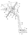
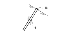
図1は本発明にかかるパイプアンカー埋設方法の概要を、斜面に直角方向に埋設する場合を例にとって示している。
1はパイプアンカー、2は前記パイプアンカー1と独立したビット、3はビット2に軸方向の打撃力と回転運動を与えるためのハンマー部3Aと回転軸部(ロッド部)3Bを直列状に備え、ビット2とつながることで構成される掘削アッセンブリーである。
Embodiments of the present invention will be described below with reference to the accompanying drawings.
FIG. 1 shows an outline of a pipe anchor embedding method according to the present invention, taking as an example a case of embedding in a direction perpendicular to a slope.
1 is a pipe anchor, 2 is a bit independent of the
4は施工場所に据付られる打ち込みフィード用の架台であり、ガイドレールを兼ねるべく長尺矩形枠状をなす本体4Aとサポート4Bを備え、前記本体4Aには、前記回転軸部を回動する可逆回転自在な掘削機としての駆動モータ5が台座5aをもって摺動可能に取り付けられ、台座5aにはウインチ6Aからのワイヤロープ60が連結され駆動モータ5を吊持するようにしている。なお、6Bは掘削アッセンブリー3とアンカーパイプを駆動モータ5と連結する際に一時的に吊持するウインチである。
前記駆動モータ5はこの例では油圧モータが用いられており、圧縮エア送給ヘッダー50を同軸に備えている。
Reference numeral 4 denotes a pedestal feed mount installed at a construction site, which is provided with a
In this example, the
7は他所に配されたエアコンプレッサであり、ホース70を介して前記駆動モータ5の圧縮エア送給ヘッダー50に接続されている。8は前記駆動モータ5に圧油を供給する発電機付きの油圧ユニットであり、近傍には制御弁などを含む操作盤8Aを有し、これからホース80を介して駆動モータ5に接続されている。
9はアンカー埋設地質が粘土質である場合に用いられる水供給系であり、水タンク9Aと、ポンプ9Bとを有し、ホース90により前記圧縮エア供給系の適所に接続される。
Reference numeral 9 denotes a water supply system used when the anchor embedding geology is clayey. The water supply system 9 has a
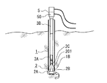
図2ないし図4は前記パイプアンカー1とビット2および掘削アッセンブリー3の詳細を示しており、パイプアンカー1は、たとえば1500〜3500mmの長さを有しており、全体に亜鉛あるいはアルミ亜鉛合金メッキが施されている。
パイプアンカー1は、上端部に吊持用のボルトを取り付ける孔を有し、埋め込み後はキャップが冠着されるようになっている。一方、先端部には、推進力受け部となるべき鋼製のリング1Bを一体に有している。
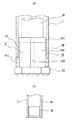
図3はその詳細を示しており、(a)はその第1例を示している。この第1例では、リング1Bはアンカー本体1Aの外径とほぼ同じ外径を有し、内径がアンカー本体1Aの内径よりも小さい。リング1Bは長手方向の適当な位置から上半部100がアンカー本体1Aの内径とほぼ合致する外径となるように薄肉化され、前記上半部100がアンカー本体1Aに内嵌されている。そして厚肉の下半部101がアンカー本体1Aの先端より延出され、上半部100と下半部101の境界部位がアンカー本体1Aと溶接されている。この実施例はアンカーパイプ1がたとえば3〜5mmというような薄肉である場合に好適である。
2 to 4 show details of the
The
FIG. 3 shows the details, and (a) shows the first example. In this first example, the
図3(b)は第2例を示しており、リング1Bは外径がアンカー本体1Aの内径とほぼ一致したストレートなものからなり、アンカー本体1Aの先端部に内嵌され、端部がアンカー本体1Aと溶接されている。
FIG. 3B shows a second example, in which the
ビット2は端面に超硬合金などからなるチップを配設していて回転方向によって拡縮可能なビットヘッド2Aと、軸状部20を後方に突出させたハウジング(デバイス)2Bを備えている。
図5はビットヘッド2Aの例を示しており、(a)(b)は偏心タイプを、(c)(d)は複数刃分割タイプを示している。いずれも、所定方向の回転時に直径D2に拡径し、反対方向の回転時に直径D1に縮径されるが、縮径時に前記リング1Bの内径と同等以下になり、拡径時にリング1Bの下半部外径よりも適度に大きな径となりえる寸法のものが選ばれる。
ハウジング2Bの後端部には、前記した推進力受け部としてのリング上半部100(第2実施例ではリング)端面に激突可能な張出し量を持ったが設けられている。
なお、ハウジング2Bはスライムの誘導のための軸線方向溝203がつば部201を貫通するように設けられている。
The
FIG. 5 shows an example of the
A rear end portion of the
The
ハンマー部3Aは筒状をなしており、先端部に前記軸状部20が回転では一体に、かつ軸方向では相対移動可能に連結し、ハンマー部3Aとハウジング2Bの間が軸方向に移動可能となっている。
The
回転軸部3Bはパイプ状をなしており、前記ハンマー部3Aの後端に同心状に連結されている。回転軸部3Bは複数本がつながれることで所要長さとなっていてもよいが、いずれにしても、回転軸部3Bの後端は前記駆動モータ5の出力軸と連結されている。したがって、回転軸部3Bが回転すると、ハンマー部3Aとビット2が同期回転される。
圧縮エア送給ヘッダー50に供給された圧縮エアは回転軸部3Bを通してハンマー部3Aに送られ、ビット2の軸状部20にあるピストン部に作用するようになっている。
The rotating
The compressed air supplied to the compressed
なお、架台4の据付けは任意であり、サポート4Bをピンアンカー40で地表に固定すればよく、さらに、必要とあらば、架台4の上部を控えロープ4Cで地表に支持させればよい。
The installation of the gantry 4 is arbitrary, and the support 4B may be fixed to the ground surface with the
本発明のパイプアンカー埋設方法を説明すると、常態において、パイプアンカー1と、ビット2を含む掘削アッセンブリー3は分離状態にあり、さらに、掘削アッセンブリー3は、ハンマー部3Aと回転軸部3Bおよびビット2に分解できるので、小型軽量化することができ、現場への搬入が容易である。
The pipe anchor embedding method according to the present invention will be described. Normally, the
埋設に当たっては、回転軸部3Bとハンマー部3Aおよびビット2を連結して掘削アッセンブリー3を組立てる。一方では、架台4をアンカー埋設予定場所に据付け、(斜面直角方向の場合、架台4は図1のように直角方向に設置する)その架台4の本体4Aに駆動モータ5を装着し、ウインチ6Aとロープ60によって吊持させる。
そして、前記掘削アッセンブリー3をパイプアンカー1の後端から挿入する。このときにはビットヘッド2Aを図5(a)のように縮径方向に回転させておく。したがってビットヘッド2Aは抵抗なくパイプアンカー1中を下降する。
In embedment, the
Then, the excavating
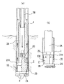
図4の仮想線はこのときの状態を示している。ビットヘッド2Aがパイプアンカー1の下端から突出したならば、回転軸部3Bとハンマー部3Aを回動する。こうすれば、図5(b)のようにビットヘッド2Aが偏心市あるいは実質的に増径して、全体あるいは一部がパイプアンカー1の外径と同等以上に拡大する。ビットヘッド2Aが抜け止めストッパーとなるので、パイプアンカー1と掘削アッセンブリー3は一体に組み付けられた状態となる。そこで、ウインチ6Bを使って全体を吊り上げ、回転軸部3Bを駆動モータ5と連結する。以上で、準備が整い、以下、掘削アッセンブリーは自重でフィードされることになる。
The virtual line in FIG. 4 shows the state at this time. If the
エアコンプレッサ7を駆動して圧縮エアをヘッダー50に供給すれば、該圧縮エアは回転軸部3B内を通過してハンマー部3A内に圧入され、ピストン部を介してビット2の軸状部20が軸方向に強圧されるため、ハウジング2Bのつば部201がアンカーのリング端面に当接するまでビット2がハンマー部3Aから突出し、したがって、ビットヘッド2Aが、リング1Bの下端(図3aの場合)あるいはパイプアンカー下端(図3bの場合)から適度に離間する。
操作盤8Aを操作して圧油を駆動モータ5に供給すれば、回転軸部3Bが回転し、これと連結しているハンマー部3Aが回転し、軸状部20を介してビット2回転する。これにより図2と図4のように、パイプアンカー1の直近前方でビットヘッド2Aが回転するため、地層の掘削穿孔が行われる。このときに、ビットハウジング2Bのつば部201がアンカーのリング端面に当接しているので、パイプアンカー1は掘削アッセンブリー3と一体に非回転のまま地中に推進されていく。
When the
If pressure oil is supplied to the
こうして推進されているときに、前方に転石、礫、岩盤部Rがあった場合には、これらはビットヘッド2Aの推進に対する抵抗として働く。その抵抗が圧縮エアの押圧力に勝ると、ビットヘッド2Aがリング1Bの下端(図3aの場合)あるいはパイプアンカー下端(図3bの場合)に当接するまで、ビット2の全体が後方に軸方向移動され、いわば短縮する。この状態が図6(a)である。このときにも前記のようにハンマー部3Aには圧縮エアが送給されているので、図6(b)のごとく、ビット2はハウジング2Bのつば部201がリング1Bの端面に当接するまで再び衝撃的に前進ストロークし、ビットヘッド2Aが転石、礫、岩盤部Rに激突する。
When there is a boulder, gravel, and rock mass R in front of the propulsion, they act as resistance to propulsion of the
そしてまた、転石、礫、岩盤部Rによる抵抗を受けると前記のように引っ込み、次いでエア圧で突出する。パイプアンカー1はビット2の前進ストローク時に、ハウジング2Bのつば部201とリング1Bの当接で掘削アッセンブリー3と一体に推進し、打ち込まれる。こうした動作の繰り返しで打撃が行われ、その間ビット2の回転は継続しており、したがって、こうした回転と打撃とによって転石、礫、岩盤部Rは短時間で効率よく破砕される。転石、礫、岩盤部Rを通過して通常の土質になったときには、ビット2がハウジング2Bのつば部201がリング1Bの端面に当接するまで前進ストロークし、図4の状態で掘削推進状態となる。
なお、前記のような掘削で生じたスライムはハウジング2Bの軸線方向溝203を経てハンマー部外周のパイプアンカー空間に排出され、回転軸部外周の空間を経て後送され、パイプアンカー後端部から排出される。
And when it receives resistance by boulders, gravel, and rock mass R, it retracts as described above and then protrudes with air pressure. During the forward stroke of the
The slime generated by the excavation as described above is discharged to the pipe anchor space on the outer periphery of the hammer portion through the axial groove 203 of the
以下、駆動モータ5による回転軸部3Bを経てのビット2の回転運動と、ハンマー部3Aへの圧縮エア供給によるビット2の打撃推進運動が行われことによりパイプアンカー1が効率よく地中深く推進される。この進行時に、駆動モータ5の台座5aは架台4のガイドレールに沿って案内されるので、駆動モータ5とそれ以下の各部は円滑にフィードされる。
前記のように、地層に転石、礫、岩盤部Rがあっても、ビットヘッド2Aの回転とハンマー部3Aの打撃によるビットヘッド2Aの衝撃的推進により確実に砕かれるので、施工地質に制限がなく、迅速、円滑に打ち込みを行うことができる。また、パイプアンカー1は回転しないので、粘土質以外、粘度質以外のほとんどの地盤において水を使用せずに施工が可能であり、掘削時の水の使用を低減できる。
Hereinafter, the
As mentioned above, even if there are boulders, gravel, and bedrock part R in the formation, the construction is limited because the
図7(a)のように所定の深さまでパイプアンカー1が進出したならば、駆動モータ5を逆方向に回転する。こうすれば、回転軸部3Bとハンマー部3Aを経て回転がビット2に伝達され、ビットヘッド2Aの外径がパイプアンカー1の先端内面にあるリング1Bの内径と同等以下に縮径される。
そこで、ウインチ6Aを操作して掘削アッセンブリー3を吊り上げれば、図7(b)のようにビットヘッド2Aがパイプアンカー1内に収納され、ビット2とハンマー部3Aおよび回転軸部3Bがパイプアンカー1内を通って引抜かれ、パイプアンカー1だけが地中に残された状態になる。図8はアンカー埋設状態を示している。
When the
If the
すなわち掘削・打ち込み完了と同時にパイプアンカー1の埋設が完了する。そして、引抜かれたビットヘッド2Aを含む掘削アッセンブリーは次のパイプアンカーに対して挿入することで繰り返し使用できるので経済的である。
パイプアンカー1は回転しないので、内外面にメッキを施しておくことができ、埋設後は図8のようにキャップ1Cを施せば腐食の心配がなく、したがって、モルタルの注入をあえて行わなくてもよくなるので、施工がより簡易、安価なものとなる。
また、アンカーは回転しないので、架台4を設置可能である限り、60度程度の斜面まで、斜面と直角方向のアンカー埋設が可能であり、斜面の段取りが不要であるため工事も簡易化できる。
That is, the burying of the
Since the
Further, since the anchor does not rotate, as long as the gantry 4 can be installed, it is possible to embed the anchor in a direction perpendicular to the slope up to a slope of about 60 degrees, and the work can be simplified because the setup of the slope is unnecessary.
1 パイプアンカー
1B リング
2 ビット
2A ビットヘッド
3 掘削アッセンブリー
3A ハンマー部
3B 回転軸部
4 架台
5 駆動モータ
1
Claims (3)
The pipe anchor embedding method according to claim 1 or 2, wherein the pipe anchor is plated with zinc or aluminum zinc alloy.
Priority Applications (1)
| Application Number | Priority Date | Filing Date | Title |
|---|---|---|---|
| JP2005219537A JP4707491B2 (en) | 2005-07-28 | 2005-07-28 | How to embed a pipe anchor |
Applications Claiming Priority (1)
| Application Number | Priority Date | Filing Date | Title |
|---|---|---|---|
| JP2005219537A JP4707491B2 (en) | 2005-07-28 | 2005-07-28 | How to embed a pipe anchor |
Related Child Applications (1)
| Application Number | Title | Priority Date | Filing Date |
|---|---|---|---|
| JP2005362467A Division JP4906335B2 (en) | 2005-12-15 | 2005-12-15 | Pipe anchor burial equipment |
Publications (3)
| Publication Number | Publication Date |
|---|---|
| JP2007032169A JP2007032169A (en) | 2007-02-08 |
| JP2007032169A5 JP2007032169A5 (en) | 2009-01-08 |
| JP4707491B2 true JP4707491B2 (en) | 2011-06-22 |
Family
ID=37791746
Family Applications (1)
| Application Number | Title | Priority Date | Filing Date |
|---|---|---|---|
| JP2005219537A Active JP4707491B2 (en) | 2005-07-28 | 2005-07-28 | How to embed a pipe anchor |
Country Status (1)
| Country | Link |
|---|---|
| JP (1) | JP4707491B2 (en) |
Cited By (1)
| Publication number | Priority date | Publication date | Assignee | Title |
|---|---|---|---|---|
| JP2019138091A (en) * | 2018-02-13 | 2019-08-22 | アビエンジニアリング株式会社 | Burying device and burying method for environmentally friendly pipe anchor |
Families Citing this family (6)
| Publication number | Priority date | Publication date | Assignee | Title |
|---|---|---|---|---|
| JP5442187B2 (en) * | 2007-07-22 | 2014-03-12 | 東京製綱株式会社 | Anchor for sloped structure |
| JP4834631B2 (en) * | 2007-09-12 | 2011-12-14 | 東京製綱株式会社 | Anchoring device for suspension structure |
| JP5878596B2 (en) * | 2014-07-17 | 2016-03-08 | 東京製綱株式会社 | Anchor device installation method |
| JP6490504B2 (en) * | 2015-06-12 | 2019-03-27 | 東京製綱株式会社 | Anchor driving method, and boring rod and casing levitation prevention metal fitting used therefor |
| JP7233829B2 (en) * | 2016-12-27 | 2023-03-07 | 東京製綱株式会社 | Steel pipe pile type landslide prevention facility and method for forming steel pipe pile type landslide prevention facility |
| JP6847655B2 (en) * | 2016-12-27 | 2021-03-24 | 東京製綱株式会社 | Anchor facility and method of forming anchor facility |
Citations (8)
| Publication number | Priority date | Publication date | Assignee | Title |
|---|---|---|---|---|
| JPH08109632A (en) * | 1994-10-11 | 1996-04-30 | Kajima Corp | Compression type permanent anchor |
| JPH08277691A (en) * | 1995-02-10 | 1996-10-22 | Mitsubishi Materials Corp | Excavating tool |
| JPH10140959A (en) * | 1996-11-15 | 1998-05-26 | Tetra Co Ltd | Excavating method and device by use of cutting bit |
| JPH11280070A (en) * | 1998-03-31 | 1999-10-12 | Tokyo Seiko Co Ltd | Anchor embedding construction method |
| JP2000104475A (en) * | 1998-09-30 | 2000-04-11 | Kencho Kobe:Kk | Underground boring machine |
| JP2001271580A (en) * | 2000-03-24 | 2001-10-05 | Norio Kagota | Excavator |
| JP2001303592A (en) * | 2000-04-20 | 2001-10-31 | Kensetsu Kiso Eng Co Ltd | Method for installing and fixing block |
| JP2004183471A (en) * | 2002-11-20 | 2004-07-02 | Mitsubishi Materials Corp | Excavating tool |
-
2005
- 2005-07-28 JP JP2005219537A patent/JP4707491B2/en active Active
Patent Citations (8)
| Publication number | Priority date | Publication date | Assignee | Title |
|---|---|---|---|---|
| JPH08109632A (en) * | 1994-10-11 | 1996-04-30 | Kajima Corp | Compression type permanent anchor |
| JPH08277691A (en) * | 1995-02-10 | 1996-10-22 | Mitsubishi Materials Corp | Excavating tool |
| JPH10140959A (en) * | 1996-11-15 | 1998-05-26 | Tetra Co Ltd | Excavating method and device by use of cutting bit |
| JPH11280070A (en) * | 1998-03-31 | 1999-10-12 | Tokyo Seiko Co Ltd | Anchor embedding construction method |
| JP2000104475A (en) * | 1998-09-30 | 2000-04-11 | Kencho Kobe:Kk | Underground boring machine |
| JP2001271580A (en) * | 2000-03-24 | 2001-10-05 | Norio Kagota | Excavator |
| JP2001303592A (en) * | 2000-04-20 | 2001-10-31 | Kensetsu Kiso Eng Co Ltd | Method for installing and fixing block |
| JP2004183471A (en) * | 2002-11-20 | 2004-07-02 | Mitsubishi Materials Corp | Excavating tool |
Cited By (1)
| Publication number | Priority date | Publication date | Assignee | Title |
|---|---|---|---|---|
| JP2019138091A (en) * | 2018-02-13 | 2019-08-22 | アビエンジニアリング株式会社 | Burying device and burying method for environmentally friendly pipe anchor |
Also Published As
| Publication number | Publication date |
|---|---|
| JP2007032169A (en) | 2007-02-08 |
Similar Documents
| Publication | Publication Date | Title |
|---|---|---|
| JP4707491B2 (en) | How to embed a pipe anchor | |
| JP4076554B2 (en) | Excavator, rotary excavator equipped with excavator and underground excavation method | |
| JP4906335B2 (en) | Pipe anchor burial equipment | |
| CN107002379B (en) | Utilize the excavating gear of excavator | |
| JP2007211412A (en) | Anchor construction method | |
| JP5005806B2 (en) | Anchor burying method for rockfall prevention | |
| JP4834631B2 (en) | Anchoring device for suspension structure | |
| CN102839915A (en) | Hydraulic high frequency rotary vibration construction device applicable to dry pneumatic rock drilling pile machine | |
| JP5442187B2 (en) | Anchor for sloped structure | |
| JP2007277979A (en) | Anchor for suspension structure on slope | |
| JP4767132B2 (en) | Rock fall prevention anchor | |
| JP2005273293A (en) | Excavating method | |
| EP2319990A2 (en) | Method and system for placing at least one foundation element in the ground | |
| JP4478348B2 (en) | Steel pipe pile driving method and apparatus | |
| JP5102893B2 (en) | Falling object capture system | |
| JP3247757B2 (en) | Cement milk injection downhole hammer | |
| KR0148437B1 (en) | Pile construction method in underground boulder zone | |
| JP4772808B2 (en) | Excavation method | |
| JP2005180112A (en) | Ground improvement structure and ground improvement method | |
| JP3875398B2 (en) | Anchor burial method | |
| JPH09302654A (en) | Construction method and device for driving steel pipe pile | |
| JP2003184499A (en) | Large diameter lock bolt anchor for natural ground reinforcement | |
| JP3388279B2 (en) | Excavation method and lock bit used for it | |
| JPH06264435A (en) | Cement milk injection type down-hole hammer | |
| JP2633460B2 (en) | Drilling method |
Legal Events
| Date | Code | Title | Description |
|---|---|---|---|
| A621 | Written request for application examination |
Free format text: JAPANESE INTERMEDIATE CODE: A621 Effective date: 20080423 |
|
| A521 | Request for written amendment filed |
Free format text: JAPANESE INTERMEDIATE CODE: A523 Effective date: 20081118 |
|
| A977 | Report on retrieval |
Free format text: JAPANESE INTERMEDIATE CODE: A971007 Effective date: 20100427 |
|
| A131 | Notification of reasons for refusal |
Free format text: JAPANESE INTERMEDIATE CODE: A131 Effective date: 20101207 |
|
| A521 | Request for written amendment filed |
Free format text: JAPANESE INTERMEDIATE CODE: A523 Effective date: 20110207 |
|
| TRDD | Decision of grant or rejection written | ||
| A01 | Written decision to grant a patent or to grant a registration (utility model) |
Free format text: JAPANESE INTERMEDIATE CODE: A01 Effective date: 20110308 |
|
| A61 | First payment of annual fees (during grant procedure) |
Free format text: JAPANESE INTERMEDIATE CODE: A61 Effective date: 20110315 |
|
| R150 | Certificate of patent or registration of utility model |
Ref document number: 4707491 Country of ref document: JP Free format text: JAPANESE INTERMEDIATE CODE: R150 |
|
| R250 | Receipt of annual fees |
Free format text: JAPANESE INTERMEDIATE CODE: R250 |
|
| R250 | Receipt of annual fees |
Free format text: JAPANESE INTERMEDIATE CODE: R250 |
|
| R250 | Receipt of annual fees |
Free format text: JAPANESE INTERMEDIATE CODE: R250 |
|
| R250 | Receipt of annual fees |
Free format text: JAPANESE INTERMEDIATE CODE: R250 |
|
| R250 | Receipt of annual fees |
Free format text: JAPANESE INTERMEDIATE CODE: R250 |
|
| R250 | Receipt of annual fees |
Free format text: JAPANESE INTERMEDIATE CODE: R250 |
|
| R250 | Receipt of annual fees |
Free format text: JAPANESE INTERMEDIATE CODE: R250 |