JP4706540B2 - Fan control device for fuel cell vehicle - Google Patents
Fan control device for fuel cell vehicle Download PDFInfo
- Publication number
- JP4706540B2 JP4706540B2 JP2006101913A JP2006101913A JP4706540B2 JP 4706540 B2 JP4706540 B2 JP 4706540B2 JP 2006101913 A JP2006101913 A JP 2006101913A JP 2006101913 A JP2006101913 A JP 2006101913A JP 4706540 B2 JP4706540 B2 JP 4706540B2
- Authority
- JP
- Japan
- Prior art keywords
- fuel cell
- battery
- fan
- vehicle
- battery fan
- Prior art date
- Legal status (The legal status is an assumption and is not a legal conclusion. Google has not performed a legal analysis and makes no representation as to the accuracy of the status listed.)
- Active
Links
Images


Classifications
-
- B—PERFORMING OPERATIONS; TRANSPORTING
- B60—VEHICLES IN GENERAL
- B60L—PROPULSION OF ELECTRICALLY-PROPELLED VEHICLES; SUPPLYING ELECTRIC POWER FOR AUXILIARY EQUIPMENT OF ELECTRICALLY-PROPELLED VEHICLES; ELECTRODYNAMIC BRAKE SYSTEMS FOR VEHICLES IN GENERAL; MAGNETIC SUSPENSION OR LEVITATION FOR VEHICLES; MONITORING OPERATING VARIABLES OF ELECTRICALLY-PROPELLED VEHICLES; ELECTRIC SAFETY DEVICES FOR ELECTRICALLY-PROPELLED VEHICLES
- B60L1/00—Supplying electric power to auxiliary equipment of vehicles
- B60L1/003—Supplying electric power to auxiliary equipment of vehicles to auxiliary motors, e.g. for pumps, compressors
-
- B—PERFORMING OPERATIONS; TRANSPORTING
- B60—VEHICLES IN GENERAL
- B60L—PROPULSION OF ELECTRICALLY-PROPELLED VEHICLES; SUPPLYING ELECTRIC POWER FOR AUXILIARY EQUIPMENT OF ELECTRICALLY-PROPELLED VEHICLES; ELECTRODYNAMIC BRAKE SYSTEMS FOR VEHICLES IN GENERAL; MAGNETIC SUSPENSION OR LEVITATION FOR VEHICLES; MONITORING OPERATING VARIABLES OF ELECTRICALLY-PROPELLED VEHICLES; ELECTRIC SAFETY DEVICES FOR ELECTRICALLY-PROPELLED VEHICLES
- B60L1/00—Supplying electric power to auxiliary equipment of vehicles
- B60L1/02—Supplying electric power to auxiliary equipment of vehicles to electric heating circuits
- B60L1/04—Supplying electric power to auxiliary equipment of vehicles to electric heating circuits fed by the power supply line
- B60L1/06—Supplying electric power to auxiliary equipment of vehicles to electric heating circuits fed by the power supply line using only one supply
- B60L1/08—Methods and devices for control or regulation
-
- B—PERFORMING OPERATIONS; TRANSPORTING
- B60—VEHICLES IN GENERAL
- B60L—PROPULSION OF ELECTRICALLY-PROPELLED VEHICLES; SUPPLYING ELECTRIC POWER FOR AUXILIARY EQUIPMENT OF ELECTRICALLY-PROPELLED VEHICLES; ELECTRODYNAMIC BRAKE SYSTEMS FOR VEHICLES IN GENERAL; MAGNETIC SUSPENSION OR LEVITATION FOR VEHICLES; MONITORING OPERATING VARIABLES OF ELECTRICALLY-PROPELLED VEHICLES; ELECTRIC SAFETY DEVICES FOR ELECTRICALLY-PROPELLED VEHICLES
- B60L50/00—Electric propulsion with power supplied within the vehicle
- B60L50/50—Electric propulsion with power supplied within the vehicle using propulsion power supplied by batteries or fuel cells
- B60L50/51—Electric propulsion with power supplied within the vehicle using propulsion power supplied by batteries or fuel cells characterised by AC-motors
-
- B—PERFORMING OPERATIONS; TRANSPORTING
- B60—VEHICLES IN GENERAL
- B60L—PROPULSION OF ELECTRICALLY-PROPELLED VEHICLES; SUPPLYING ELECTRIC POWER FOR AUXILIARY EQUIPMENT OF ELECTRICALLY-PROPELLED VEHICLES; ELECTRODYNAMIC BRAKE SYSTEMS FOR VEHICLES IN GENERAL; MAGNETIC SUSPENSION OR LEVITATION FOR VEHICLES; MONITORING OPERATING VARIABLES OF ELECTRICALLY-PROPELLED VEHICLES; ELECTRIC SAFETY DEVICES FOR ELECTRICALLY-PROPELLED VEHICLES
- B60L58/00—Methods or circuit arrangements for monitoring or controlling batteries or fuel cells, specially adapted for electric vehicles
- B60L58/10—Methods or circuit arrangements for monitoring or controlling batteries or fuel cells, specially adapted for electric vehicles for monitoring or controlling batteries
- B60L58/24—Methods or circuit arrangements for monitoring or controlling batteries or fuel cells, specially adapted for electric vehicles for monitoring or controlling batteries for controlling the temperature of batteries
- B60L58/26—Methods or circuit arrangements for monitoring or controlling batteries or fuel cells, specially adapted for electric vehicles for monitoring or controlling batteries for controlling the temperature of batteries by cooling
-
- B—PERFORMING OPERATIONS; TRANSPORTING
- B60—VEHICLES IN GENERAL
- B60L—PROPULSION OF ELECTRICALLY-PROPELLED VEHICLES; SUPPLYING ELECTRIC POWER FOR AUXILIARY EQUIPMENT OF ELECTRICALLY-PROPELLED VEHICLES; ELECTRODYNAMIC BRAKE SYSTEMS FOR VEHICLES IN GENERAL; MAGNETIC SUSPENSION OR LEVITATION FOR VEHICLES; MONITORING OPERATING VARIABLES OF ELECTRICALLY-PROPELLED VEHICLES; ELECTRIC SAFETY DEVICES FOR ELECTRICALLY-PROPELLED VEHICLES
- B60L58/00—Methods or circuit arrangements for monitoring or controlling batteries or fuel cells, specially adapted for electric vehicles
- B60L58/40—Methods or circuit arrangements for monitoring or controlling batteries or fuel cells, specially adapted for electric vehicles for controlling a combination of batteries and fuel cells
-
- B—PERFORMING OPERATIONS; TRANSPORTING
- B60—VEHICLES IN GENERAL
- B60L—PROPULSION OF ELECTRICALLY-PROPELLED VEHICLES; SUPPLYING ELECTRIC POWER FOR AUXILIARY EQUIPMENT OF ELECTRICALLY-PROPELLED VEHICLES; ELECTRODYNAMIC BRAKE SYSTEMS FOR VEHICLES IN GENERAL; MAGNETIC SUSPENSION OR LEVITATION FOR VEHICLES; MONITORING OPERATING VARIABLES OF ELECTRICALLY-PROPELLED VEHICLES; ELECTRIC SAFETY DEVICES FOR ELECTRICALLY-PROPELLED VEHICLES
- B60L2240/00—Control parameters of input or output; Target parameters
- B60L2240/40—Drive Train control parameters
- B60L2240/54—Drive Train control parameters related to batteries
- B60L2240/545—Temperature
-
- B—PERFORMING OPERATIONS; TRANSPORTING
- B60—VEHICLES IN GENERAL
- B60L—PROPULSION OF ELECTRICALLY-PROPELLED VEHICLES; SUPPLYING ELECTRIC POWER FOR AUXILIARY EQUIPMENT OF ELECTRICALLY-PROPELLED VEHICLES; ELECTRODYNAMIC BRAKE SYSTEMS FOR VEHICLES IN GENERAL; MAGNETIC SUSPENSION OR LEVITATION FOR VEHICLES; MONITORING OPERATING VARIABLES OF ELECTRICALLY-PROPELLED VEHICLES; ELECTRIC SAFETY DEVICES FOR ELECTRICALLY-PROPELLED VEHICLES
- B60L2250/00—Driver interactions
- B60L2250/26—Driver interactions by pedal actuation
- B60L2250/28—Accelerator pedal thresholds
-
- B—PERFORMING OPERATIONS; TRANSPORTING
- B60—VEHICLES IN GENERAL
- B60L—PROPULSION OF ELECTRICALLY-PROPELLED VEHICLES; SUPPLYING ELECTRIC POWER FOR AUXILIARY EQUIPMENT OF ELECTRICALLY-PROPELLED VEHICLES; ELECTRODYNAMIC BRAKE SYSTEMS FOR VEHICLES IN GENERAL; MAGNETIC SUSPENSION OR LEVITATION FOR VEHICLES; MONITORING OPERATING VARIABLES OF ELECTRICALLY-PROPELLED VEHICLES; ELECTRIC SAFETY DEVICES FOR ELECTRICALLY-PROPELLED VEHICLES
- B60L2270/00—Problem solutions or means not otherwise provided for
- B60L2270/10—Emission reduction
- B60L2270/14—Emission reduction of noise
- B60L2270/142—Emission reduction of noise acoustic
-
- Y—GENERAL TAGGING OF NEW TECHNOLOGICAL DEVELOPMENTS; GENERAL TAGGING OF CROSS-SECTIONAL TECHNOLOGIES SPANNING OVER SEVERAL SECTIONS OF THE IPC; TECHNICAL SUBJECTS COVERED BY FORMER USPC CROSS-REFERENCE ART COLLECTIONS [XRACs] AND DIGESTS
- Y02—TECHNOLOGIES OR APPLICATIONS FOR MITIGATION OR ADAPTATION AGAINST CLIMATE CHANGE
- Y02T—CLIMATE CHANGE MITIGATION TECHNOLOGIES RELATED TO TRANSPORTATION
- Y02T10/00—Road transport of goods or passengers
- Y02T10/60—Other road transportation technologies with climate change mitigation effect
- Y02T10/70—Energy storage systems for electromobility, e.g. batteries
Landscapes
- Engineering & Computer Science (AREA)
- Power Engineering (AREA)
- Transportation (AREA)
- Mechanical Engineering (AREA)
- Life Sciences & Earth Sciences (AREA)
- Sustainable Development (AREA)
- Sustainable Energy (AREA)
- Fuel Cell (AREA)
- Arrangement Or Mounting Of Propulsion Units For Vehicles (AREA)
- Electric Propulsion And Braking For Vehicles (AREA)
Description
本発明は、燃料電池車両のファン制御装置に関する。 The present invention relates to a fan control device for a fuel cell vehicle.
従来、車両が停車してエンジン等の作動音が存在しないときには、バッテリファンを停止させ、またはバッテリファンの回転数を低下させることで、バッテリファンの作動音を車両乗員に認識させ難くしたファン制御装置が知られている。また、このファン制御装置がハイブリッド車や燃料電池車両に搭載されている場合、該装置は、アイドル停止が予測されるときに、アイドル停止される以前にバッテリファンへの作動指令を低下させる構成となっている(例えば特許文献1参照)。 Conventionally, fan control that makes it difficult for vehicle occupants to recognize the operation sound of the battery fan by stopping the battery fan or lowering the rotation speed of the battery fan when the vehicle stops and there is no operation sound of the engine or the like. The device is known. Further, when the fan control device is mounted on a hybrid vehicle or a fuel cell vehicle, the device reduces the operation command to the battery fan before the idling stop when the idling stop is predicted. (For example, refer to Patent Document 1).
ところが、ハイブリッド車などがアイドル運転停止の状態であっても、音響機器や空調機の動作状態によっては車室内が静寂とは限らず、騒音レベルが高い場合もあり得る。このような場合、バッテリファンを高回転させてバッテリを冷却することが望ましい。 However, even if the hybrid vehicle or the like is in an idle operation stop state, depending on the operating state of the audio equipment or the air conditioner, the interior of the vehicle is not always quiet, and the noise level may be high. In such a case, it is desirable to cool the battery by rotating the battery fan at a high speed.
そこで、アイドル運転停止の状態であっても車室内の騒音レベルに基づいて、バッテリファンの動作状態を制御するファン制御装置が知られている。この装置では、アイドル運転停止の状態であっても車室内が静寂でなければ、バッテリの温度上昇を防ぐために、バッテリファンを駆動させ、好適にバッテリ温度を抑制するようにしている(例えば特許文献2参照)。
燃料電池車両では大気中の空気をコンプレッサによって圧縮して燃料電池へ供給する構成となっている。このコンプレッサは車室内の騒音レベルを上げる一因となっており、車室内の騒音レベルを考慮した従来の特許文献2に記載の発明を燃料電池車両に適用した場合、コンプレッサの作動音(回転数)に応じてバッテリファンを回転させることとなる。
In a fuel cell vehicle, air in the atmosphere is compressed by a compressor and supplied to the fuel cell. This compressor contributes to raising the noise level in the passenger compartment. When the conventional invention described in
しかし、コンプレッサの回転数に応じてバッテリファンを回転させると、車両乗員にとって違和感があるものとなってしまう。 However, if the battery fan is rotated according to the rotation speed of the compressor, the vehicle occupant will feel uncomfortable.
本発明はこのような従来の課題を解決するためになされたものであり、その目的とするところは、車両乗員に与える違和感を軽減することが可能な燃料電池車両のファン制御装置を提供することにある。 The present invention has been made to solve such a conventional problem, and an object of the present invention is to provide a fan control device for a fuel cell vehicle capable of reducing a sense of discomfort given to a vehicle occupant. It is in.
本発明のファン制御装置は、燃料電池システムと、駆動モータと、2次電池と、バッテリファンと、制御手段とを備えている。燃料電池システムは燃料ガスとコンプレッサから供給される酸化剤ガスとを反応させて発電するものである。駆動モータは燃料電池システムから電力の供給を受けて車両走行のための推進力を発生させる。2次電池は燃料電池システムおよび駆動モータと電力の授受を行う。バッテリファンは2次電池を冷却するものである。制御手段はバッテリファンの回転数を制御するものである。さらに、制御手段は、運転者のアクセルペダルの踏み込み量が大きくなるに従って、バッテリファンの回転数を高くする構成となっている。 The fan control device of the present invention includes a fuel cell system, a drive motor, a secondary battery, a battery fan, and control means. The fuel cell system generates power by reacting a fuel gas with an oxidant gas supplied from a compressor. The drive motor is supplied with electric power from the fuel cell system and generates a driving force for traveling the vehicle. The secondary battery exchanges power with the fuel cell system and the drive motor. The battery fan cools the secondary battery. The control means controls the rotational speed of the battery fan. Further, the control means is configured to increase the rotational speed of the battery fan as the amount of depression of the driver's accelerator pedal increases.
本発明によれば、運転者のアクセルペダルの踏み込み量が大きくなるに従って、バッテリファンの回転数を高くすることとしている。このため、バッテリファンの作動音と運転者の操作と同期させることとなり、違和感を軽減することできる。 According to the present invention, the rotation speed of the battery fan is increased as the amount of depression of the driver's accelerator pedal increases. For this reason, it synchronizes with the operation sound of a battery fan, and a driver | operator's operation, and can reduce discomfort.
以下、本発明の好適な実施形態を図面に基づいて説明する。 DESCRIPTION OF EXEMPLARY EMBODIMENTS Hereinafter, preferred embodiments of the invention will be described with reference to the drawings.
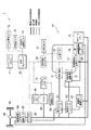
図1は、本発明の第1実施形態に係るファン制御装置の構成図である。なお、図1において、二重実線は機械力の伝達経路を示し、実線は電力線を示し、細い破線は制御線を示し、太い破線は冷却水の循環経路を示している。同図に示すように、ファン制御装置1は、燃料電池システム10と、駆動モータ20と、バッテリ(2次電池)30と、バッテリファン40と、車両コントローラ(制御手段)50とを備えている。
FIG. 1 is a configuration diagram of a fan control device according to the first embodiment of the present invention. In FIG. 1, a double solid line indicates a transmission path of mechanical force, a solid line indicates a power line, a thin broken line indicates a control line, and a thick broken line indicates a circulation path of cooling water. As shown in FIG. 1, the
燃料電池システム10は、水素ガスなどの燃料ガスとコンプレッサ(不図示)から供給される空気(酸素)などの酸化剤ガスとを反応させて発電するものである。駆動モータ20は、燃料電池システム10から電力の供給を受けて車両走行のための推進力を発生させるものである。バッテリ30は、燃料電池システム10および駆動モータ20と電力の授受を行うものである。バッテリ30は、例えばリチウムイオン電池、ニッケル水素電池および鉛電池などの各種電池や、電気二重層キャパシタおよびレドックスキャパシタなどの各種キャパシタが用いられる。バッテリファン40は、ファンが回転させられることにより送風を行い、この送風によってバッテリ30を冷却するものである。車両コントローラ50は、バッテリファン40の回転数を制御するものである。
The
このようなファン制御装置1が搭載される燃料電池車両は、燃料電池システム10により発電を行い、得られた電力を駆動モータ20に供給して走行することとなる。また、燃料電池システム10は、バッテリ30の充電量が不足している場合、発電電力をバッテリ30に供給する。また、バッテリ30は、燃料電池システム10から駆動モータ20に供給される電力量が、必要とされる電力量に満たない場合、不足分の電力を駆動モータ20に供給する。さらに、車両減速時などには、駆動モータ20は発電機として機能し、得られた発電電力をバッテリ30に供給することとなる。
A fuel cell vehicle equipped with such a
ファン制御装置1の構成についてより詳しく説明する。燃料電池システム10は、燃料電池11と、燃料電池駆動補器12と、燃料電池系循環ポンプ13と、第1ラジエータ14と、ラジエータファン15と、水温センサ16と、大気圧センサ17と、燃料電池コントローラ18とを有している。
The configuration of the
燃料電池11は、燃料ガスの供給を受ける燃料極と、酸化剤ガスの供給を受ける酸化剤極とを有し、供給された燃料ガスと酸化剤ガスとを反応させて発電する構成となっている。また、燃料極と酸化剤極とは固体高分子電解質膜を挟んで重ね合わされて発電セルを構成しており、燃料電池11は、これら発電セルが複数層積層されたスタック構造となっている。
The
燃料電池駆動補器12は、各種弁、センサ、および流量計などである。燃料電池系循環ポンプ13は、燃料電池11および燃料電池駆動補器12などを冷却するための冷却水を循環させるための駆動源となるものである。第1ラジエータ14は、外気と熱交換することにより、燃料電池11などを冷却することによって暖められた冷却水を再冷却するものである。ラジエータファン15は、ファンが回転させられることにより送風を行い、この送風によって第1ラジエータ14の冷却能力を調整するものである。水温センサ16は、燃料電池11および燃料電池駆動補器12などを冷却するための冷却水の温度を検出するものである。大気圧センサ17は、燃料電池車両の周囲の気圧を検出するものである。
The fuel cell driving
燃料電池コントローラ18は、燃料電池駆動補器12や燃料電池系循環ポンプ13の回転数を制御するものである。また、燃料電池コントローラ18は、水温センサ16の検出値に基づいて、ラジエータファン15のファン回転数を制御し、冷却水の温度を調整する構成となっている。さらに、燃料電池コントローラ18は、車両コントローラ50から指令される発電量に応じて燃料電池11に供給する燃料ガス量や酸化剤ガス量を制御するようになっている。このとき、燃料電池コントローラ18は、コンプレッサを回転させて燃料電池11に酸化剤ガスを供給する。コンプレッサの回転数は、供給すべき酸化剤ガス量と大気圧センサ17の検出値とから決定される。
The
また、ファン制御装置1は、第1DC/DCコンバータ61、インバータ62、第2DC/DCコンバータ63、減速装置64、駆動輪65、差動装置66、強電系冷却水ポンプ67、第2ラジエータ68、温度センサ69、バッテリコントローラ70、ナビゲーションシステム71、アクセル開度センサ72、外気温センサ73、および車室内騒音センサ74を備えている。
The
第1DC/DCコンバータ61は、燃料電池11とバッテリ30との電圧を等電位に調整したうえで、インバータ62を介して駆動モータ20に電力供給するものである。第2DC/DCコンバータ63は、燃料電池11やバッテリ30の高電圧を低電圧へ変換し、燃料電池駆動補器12やウィンカーやライトなどの車両補器(不図示)へ電力を分配するものである。減速装置64は、駆動モータ20の駆動力を所定の減速比で減速し駆動輪65に伝えるものであり、差動装置66は、カーブなどで左右の駆動輪65の回転をスムーズにするためのものである。
The first DC /
強電系冷却水ポンプ67は、第1および第2DC/DCコンバータ61,63、インバータ62、駆動モータ20、減速装置64、および燃料電池駆動補器12を冷却するための冷却水を循環させるための駆動源となるものである。第2ラジエータ68は、外気と熱交換することにより、駆動モータ20などを冷却することによって暖められた冷却水を再冷却するものである。この第2ラジエータ68は、上記したラジエータファン15によって冷却能力が調整されるようになっている。温度センサ69は、バッテリ30の温度を検出するものである。バッテリコントローラ70は、バッテリ30の充電量を検出するものである。
The high-power system cooling
ナビゲーションシステム71は、走行中の自車両の現在位置および進行方向などの情報を人工衛星・地磁気計・走行距離計などを利用して測定し、自車位置から目的地に至るまでの経路を車両乗員に案内するものである。アクセル開度センサ72はアクセル開度を検出するものである。外気温センサ73は燃料電池車両の周囲の外気温度を検出するものである。車室内騒音センサ74は車室内の騒音の大きさを検出するものである。
The
さらに、上記した車両コントローラ50について詳細に説明する。車両コントローラ50は、マイクロコンピュータやその周辺部品から構成されており、運転者からの要求に応じて駆動モータ20のトルクを制御し、燃料電池コントローラ18に対しインバータ62に供給すべき電力量の情報を送信する構成となっている。また、車両コントローラ50は、バッテリコントローラ70により検出された充電量に応じて、燃料電池コントローラ18に対しバッテリ30に供給すべき電力量の情報を送信する。また、車両コントローラ50は、減速時等に駆動モータ20によって発電された電力のバッテリ30への充電量を制御する構成となっている。
Further, the above-described
さらに、車両コントローラ50は、バッテリファン40の回転数を制御するようになっている。バッテリ30は充放電を繰り返すことにより内部抵抗によって発熱し温度が上昇してしまう。そして、バッテリ30の温度が高くなると内部抵抗が増大するなどの性能劣化が助長されてしまう。車両コントローラ50は、性能劣化を抑制すべくバッテリファン40の送風によってバッテリ30の温度を下げることとしている。なお、車両コントローラ50は、バッテリファン40の回転数をコンプレッサの回転数に応じて制御するようにしていない。図2を参照して、バッテリファン40の回転数をコンプレッサの回転数に応じて制御しない理由を説明する。
Furthermore, the
図2は、車両加速時における各種出力等を示す図である。まず、時刻aにおいて車両が停止しているとする。そして、時刻bにおいて車両が加速し始め、車速は時刻bから時刻fまで掛けてゆっくりと上昇する。また、駆動モータ20の駆動力は、時刻bから上昇し、時刻dで最大となり、その後時刻fまで掛けてやや減少しながら安定していくようになっている。一方、コンプレッサは、時刻b〜cにおいて燃料電池11に酸化剤ガスを供給すべく高回転するが、その後、時刻cにおいて一度回転数が減少する。そして、コンプレッサは時刻cから時刻fまで掛けて回転数が安定していくこととなる。
FIG. 2 is a diagram illustrating various outputs during vehicle acceleration. First, it is assumed that the vehicle is stopped at time a. Then, the vehicle starts to accelerate at time b, and the vehicle speed slowly increases from time b to time f. The driving force of the
この図2からも明らかなように、コンプレッサの回転数は、車速や駆動モータ20の駆動力と同期していない。ここで、運転者は、運転操作(アクセルの踏み込み量)とバッテリファン40の回転数とが同期すると、違和感を感じにくい傾向にある。故に、コンプレッサの回転数に応じてバッテリファンを回転させるとすると、アクセルの踏み込み量とバッテリファン40の回転数とが同期せず、車両乗員、特に運転者に違和感を与えてしまう。
As apparent from FIG. 2, the rotational speed of the compressor is not synchronized with the vehicle speed or the driving force of the driving
そこで、本実施形態において車両コントローラ50は、コンプレッサの回転数によらず、運転者のアクセルペダルの踏み込み量(アクセル開度)が大きくなるに従って、バッテリファン40の回転数を高くするようにしている。これにより、バッテリファン40の作動音と運転者のアクセル操作と同期させることとなり、違和感を軽減することができる。
Therefore, in the present embodiment, the
図3は、図1に示した車両コントローラ50の詳細を示す構成図である。なお、図3では、接続関係を明確とするため、車両コントローラ50以外の構成についても図示するものとする。
FIG. 3 is a block diagram showing details of the
車両コントローラ50は、バッテリ温度レベル判定部51、バッテリファン基本動作決定部52、バッテリファン運転点演算部53、車室内騒音レベル判定部54、およびバッテリファン運転点指令値演算部55を備えている。バッテリ温度レベル判定部51は、温度センサ69の検出値に基づいて、バッテリ30の温度を判定するものである。このバッテリ温度レベル判定部51は、バッテリ温度を4段階に判定するようになっている。すなわち、バッテリ温度レベル判定部51は、バッテリ温度が「レベル1(低温)」「レベル2(やや低温)」「レベル3(やや高温)」および「レベル4(高温)」のいずれに属するかを判定するようになっている。
The
バッテリファン基本動作決定部52は、バッテリ温度レベル判定部51により判定された温度レベルに応じて、バッテリファン40の基本となる回転数(以下基本回転数という)を決定するものである。このバッテリファン基本動作決定部52は、図4に示すような動作マップを記憶しており、このマップに従ってバッテリファン40の基本回転数を決定するようになっている。
The battery fan basic
図4は、図3に示すバッテリファン基本動作決定部52が記憶する動作マップを示す図である。同図に示すように、バッテリファン基本動作決定部52は、温度レベルが高くなるに従ってバッテリファン40の基本回転数を高く決定する。これにより、バッテリ30の温度が高くなるに従って送風量を多くすることとなり、バッテリ30を適切に冷却することができる。
FIG. 4 is a diagram showing an operation map stored by the battery fan basic
再度、図3を参照する。バッテリファン運転点演算部53は、アクセル開度センサ72の検出値に応じて、バッテリファン基本動作決定部52により決定されたバッテリファン40の基本回転数を補正するものである。このバッテリファン運転点演算部53は、図5に示すようなマップを記憶しており、このマップから得られる風量係数に基づいてバッテリファン40の回転数を補正するようになっている。具体的にバッテリファン運転点演算部53は、バッテリファン基本動作決定部52により決定されたバッテリファン40の回転数から得られる風量を求め、この風量に風量係数を乗じて補正風量を求め、求めた補正風量が得られるバッテリファン40の回転数を算出することによって、バッテリファン40の基本回転数を補正するようになっている。
FIG. 3 will be referred to again. The battery fan operating
図5は、図3に示すバッテリファン運転点演算部53が記憶するマップを示す図である。同図に示すように、バッテリファン運転点演算部53は、アクセル開度が大きくなるに従って、風量係数を高く決定する。風量係数は最小が「0.1」で最大が「3」であり、アクセル開度がA%以上の領域では最大の「3」となる。この補正により、車両コントローラ50は、アクセルペダルの踏み込み量が大きくなるに従ってバッテリファン40の回転数を高くすることとなる。なお、温度レベル4の場合、バッテリファン運転点演算部53は、バッテリファン40の基本回転数の補正を行わず最大の回転数とする。
FIG. 5 is a diagram showing a map stored in battery fan operating
図6は、補正後のバッテリファン40の風量を示す図である。同図に示すように、温度レベル1〜温度レベル3のいずれの場合においても、アクセル開度が大きくなるに従ってバッテリファン40の風量が高くなっている。なお、バッテリファン40の風量には最大風量があり、図6からも明らかなようにバッテリファン運転点演算部53は、温度レベル2および温度レベル3の場合、最大風量を超えないように補正することとなる。
FIG. 6 is a diagram illustrating the air volume of the
再度、図3を参照する。車室内騒音レベル判定部54は、車室内の騒音の大きさを判定するものである。この車室内騒音レベル判定部54は、車室内騒音センサ74の検出値に基づいて車室内の騒音の大きさを判定する。また、車室内騒音レベル判定部54は、図3に示すように空調装置75や音響装置76に接続され、それぞれの稼働状態の情報を読み込んで、車室内の騒音の大きさを判定するように構成されていてもよい。さらに、車室内騒音レベル判定部54は、大気圧センサ17により検出される燃料電池車両の周囲の気圧に応じて、燃料電池車両の車室内の騒音を補正することが望ましい。高地などの大気圧が低い環境下では、燃料電池11の発電量が同じであっても、コンプレッサの回転数は高くしなければならず、コンプレッサによる騒音が大きくなるためである。
FIG. 3 will be referred to again. The vehicle interior noise
バッテリファン運転点指令値演算部55は、バッテリファン運転点演算部53により補正されたバッテリファン40の回転数を、車室内騒音レベル判定部54により判定された騒音レベルに応じて再度補正するものである。このバッテリファン運転点指令値演算部55は、図7に示すマップを記憶しており、このマップから得られる回転数係数に基づいてバッテリファン40の回転数を再補正するようになっている。
The battery fan operation point command
図7は、図3に示すバッテリファン運転点指令値演算部55が記憶するマップを示す図である。同図に示すように、バッテリファン運転点指令値演算部55は、車室内騒音が大きくなるに従って、回転数係数を高く決定する。回転数係数は最小が「0.1」で最大が「3」であり、車室内騒音がB(db)以上の領域では最大の「3」となる。この補正により、車両コントローラ50は、燃料電池車両の車室内の騒音が大きくなるに従って、バッテリファン40の回転数を高くすることとなる。すなわち、車室内の騒音が小さい場合にはバッテリファン40の回転数を小さくすることとなる。これにより、車室内騒音が小さい場合にバッテリファン40の回転による騒音が目立ってしまい、車両乗員を不快にしてしまう事態を防止することができる。なお、バッテリファン運転点指令値演算部55の補正によっても、バッテリファン40の回転数は最大回転数を超えることはない。
FIG. 7 is a diagram showing a map stored in battery fan operating point command
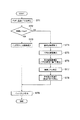
次に、本実施形態に係るファン制御装置1の動作を説明する。図8は、本実施形態に係るファン制御装置1の詳細を示すフローチャートである。同図に示すように、まず、車両コントローラ50のバッテリ温度レベル判定部51は、バッテリコントローラ70からバッテリ温度の情報を取得し、バッテリ30の温度レベルを判定する(ST1)。このとき、バッテリ温度レベル判定部51は、バッテリ30の温度が温度レベル1〜4のいずれに属するかを判定する。
Next, the operation of the
次に、バッテリ温度レベル判定部51は、バッテリ30の温度レベルが「4」であるか否かを判断する(ST2)。ここで、バッテリ30の温度レベルが「4」であると判断した場合(ST2:YES)、車両コントローラ50は、バッテリ30を冷却すべくバッテリファン40の回転数を最大回転数とする(ST3)。そして、処理はステップST9に移行する。
Next, the battery temperature
一方、バッテリ30の温度レベルが「4」でないと判断した場合(ST2:NO)、バッテリファン基本動作決定部52は、バッテリファン40の基本回転数を決定する(ST4)。このとき、バッテリファン基本動作決定部52は、図4を参照して説明したように、バッテリ30の温度レベルに応じて基本回転数を決定する。
On the other hand, when it is determined that the temperature level of the
その後、アクセル開度センサ72はアクセル開度を検出する(ST5)。次いで、バッテリファン運転点演算部53は、検出されたアクセル開度に基づいて、基本回転数を補正する(ST6)。このとき、バッテリファン運転点演算部53は、図5を参照して説明したように風量係数を求め、風量係数からバッテリファン40の基本回転数を補正する。
Thereafter, the
その後、車室内騒音レベル判定部54は、車室内の騒音レベルを判定する(ST7)。次いで、バッテリファン運転点指令値演算部55は、バッテリファン40の回転数を再補正する(ST8)。このとき、バッテリファン運転点指令値演算部55は、図7を参照して説明したように回転数係数を求め、回転数係数からバッテリファン40の回転数を再補正する。そして、処理はステップST9に移行する。
Thereafter, the vehicle interior noise
ステップST9において車両コントローラ50は、決定・補正した回転数となるように、バッテリファン40に指令をする(ST9)。その後、図8に示す処理は終了する。なお、図8に示す処理は、ファン制御装置1の電源がオフするまで繰り返し実行されるものとする。
In step ST9, the
このようにして、第1実施形態に係るファン制御装置1によれば、運転者のアクセルペダルの踏み込み量が大きくなるに従って、バッテリファン40の回転数を高くすることとしている。このため、バッテリファン40の作動音と運転者の操作と同期させることとなり、違和感を軽減することできる。すなわち、運転者がアクセルペダルを踏み込んだ場合にバッテリファン40の回転数を高くすることで、バッテリファン40の作動音は運転者の操作に応じて変化することとなり、運転者に違和感を与え難くすることができる。一方、運転者がアクセルペダルを離した場合、バッテリファン40の回転数を下げることで、同様に運転者に違和感を与え難くすることができる。
In this way, according to the
ここで、アクセルペダルの踏み込み量に応じてバッテリファン40の回転数を制御して違和感を軽減させたとしても、車室の防音性能によってはバッテリファン40の回転によって車室内環境を不快とさせてしまう可能性がある。そこで、本実施形態では、燃料電池車両の車室内の騒音が大きくなるに従ってバッテリファン40の回転数を高くする。これにより、車室内の騒音が小さい場合にはバッテリファン40の回転数を小さくすることとなり、不快感を軽減することができる。
Here, even if the rotational speed of the
また、燃料電池システム10が発電する際には、発電量に応じた空気量をコンプレッサにて圧縮し、燃料電池11へ供給する必要がある。このため、高地などの大気圧が低い環境下では、燃料電池11の発電量が同じであっても、コンプレッサの回転数は高くしなければならない。そこで、本実施形態では、燃料電池車両の周囲の気圧に応じて燃料電池車両の車室内の騒音を補正することで、車室内の騒音レベルを適切に判断し、バッテリファン40の回転による不快感を適切に軽減することができる。
Further, when the
また、バッテリ30の温度が高くなるに従ってバッテリファン40の回転数を高くするため、バッテリ30を適切に冷却することができる。
Moreover, since the rotation speed of the
次に、本発明の第2実施形態を説明する。第2実施形態に係るファン制御装置は、第1実施形態のものと同様であるが、構成および処理内容が異なっている。以下、第1実施形態との相違点を説明する。 Next, a second embodiment of the present invention will be described. The fan control device according to the second embodiment is the same as that of the first embodiment, but the configuration and processing contents are different. Hereinafter, differences from the first embodiment will be described.
図9は、本発明の第2実施形態に係るファン制御装置の構成図である。同図に示すように、第2実施形態に係るファン制御装置2は、アクセル開度センサ72に代えて、燃料電池車両の車速を検出する車速センサ77を備えている。また、車両コントローラ50は、アクセル開度に代えて、駆動モータ20の駆動力に応じてバッテリファン40の基本回転数を補正する構成となっている。
FIG. 9 is a configuration diagram of a fan control device according to the second embodiment of the present invention. As shown in the figure, the
図10は、図9に示した車両コントローラ50の詳細を示す構成図である。なお、図10では、接続関係を明確とするため、車両コントローラ50以外の構成についても図示するものとする。
FIG. 10 is a block diagram showing details of the
第2実施形態において車両コントローラ50は、駆動モータ20の駆動力が大きくなるに従ってバッテリファン40の回転数を高くする。具体的に説明すると、車両コントローラ50は駆動力推定部56を有しており、この駆動力推定部56において駆動モータ20の駆動力を推定するようになっている。駆動力推定部56は、自車両が走行する路面の勾配情報をナビゲーションシステム71から入力する。また、駆動力推定部56は、車速センサ77から自車両の車速情報を入力する。さらに、駆動力推定部56は、走行抵抗マップを記憶しており、ナビゲーションシステム71からの勾配情報と車速センサ77からの車速情報とを、走行抵抗マップに照らし合わせて走行抵抗を求める。そして、駆動力推定部56は、求めた走行抵抗を駆動モータ20の駆動力とする。なお、走行抵抗は、主に車速の2乗に比例する空気抵抗と、車速に比例するタイヤ転がり抵抗と、勾配によって算出される値である。また、走行抵抗マップとは、駆動モータ20のN−T特性と各勾配の走行抵抗曲線の釣り合いを表すマップであり、勾配情報と車速とから車両の走行抵抗を求めることができるものをいう。また、駆動モータ20の駆動力は、これに限るものでなく、他の方法等によって取得されてもよい。
In the second embodiment, the
さらに、第2実施形態においてバッテリファン運転点演算部53は、アクセル開度によらず、駆動モータ20の駆動力に応じてバッテリファン40の基本回転数を補正する構成となっている。具体的にバッテリファン運転点演算部53は、図11に示すようなマップを記憶しており、このマップから得られる風量係数に基づいてバッテリファン40の回転数を補正する。
Furthermore, in the second embodiment, the battery fan operating
図11は、図10に示すバッテリファン運転点演算部53が記憶するマップを示す図である。同図に示すように、バッテリファン運転点演算部53は、駆動モータ20の駆動力が大きくなるに従って、風量係数を高く決定する。風量係数は、第1実施形態と同様であり、最小が「0.1」で最大が「3」であり、駆動力がC以上の領域では最大の「3」となる。この補正により、車両コントローラ50は、駆動モータ20の駆動力が大きくなるに従ってバッテリファン40の回転数を高くすることとなる。
FIG. 11 is a diagram showing a map stored in battery fan operating
このようにして、第2実施形態に係るファン制御装置2によれば、駆動モータ20の駆動力が大きくなるに従ってバッテリファン40の回転数を高くしている。ここで、第1実施形態のように、運転者のアクセルペダルの踏み込み量が大きくなるに従ってバッテリファン40の回転数を高くすると、バッテリファン40の作動音を運転者の操作に同期させ、運転者の違和感を軽減することができる。しかし、駆動モータ20の応答性よりも早いアクセル操作がなされた場合には、アクセルペダルを操作したにも拘わらず車両の挙動に変化がない時間帯が発生し、この時間帯では、車両の挙動よりもバッテリファン40の作動音が先行することになる。この場合、運転者に関してはアクセルペダルの操作とバッテリファン40の回転数とが同期するため違和感が少ないが、運転者以外の乗員については車両の挙動とバッテリファン40の回転数とが遊離して感じられ違和感を感じてしまう可能性がある。ところが、第2実施形態によれば、駆動モータ20の駆動力が大きくなるに従ってバッテリファン40の回転数を高くするため、駆動モータ20の応答性よりも早いアクセル操作がされた場合であっても、運転者以外の乗員に与える違和感を軽減することできる。
Thus, according to the
また、走行抵抗マップ等を用いて車両の走行抵抗を求め、この走行抵抗を駆動モータ20の駆動力としてバッテリファン40の回転数を制御することとしている。ここで、図2を参照すると、車両が運転者の目標とする車速に近くなった場合(時刻e以降)、アクセルペダルの踏み込み量が減少して駆動モータ20の駆動力は小さくなる(時刻e〜f)。そして、その後加速度は零になる(時刻f以降)。このため、時刻e〜f間では車速が上昇しているにも拘わらず駆動モータ20の駆動力が小さくなり、実際の駆動モータ20の駆動力を計測してバッテリファン40の回転数を制御することとなると、車速が上昇しているにも拘わらずバッテリファン40の回転数は減少することとなる。これにより、車速とバッテリファン40の回転数とに遊離が生じて運転者以外の乗員に違和感を与えることとなる。ところが、本実施形態では、車両の走行抵抗を駆動モータ20の駆動力としてバッテリファン40の回転数を制御するため、車速の上昇に応じてバッテリファン40の回転数を制御することとなり、運転者以外の乗員に与える違和感を軽減することできる。
Further, the running resistance of the vehicle is obtained using a running resistance map or the like, and the rotational speed of the
さらに、第2実施形態によれば、第1実施形態と同様に、不快感を軽減することができ、バッテリファン40の回転による不快感を適切に軽減することができ、バッテリ30を適切に冷却することができる。
Furthermore, according to the second embodiment, similarly to the first embodiment, discomfort can be reduced, discomfort caused by rotation of the
次に、本発明の第3実施形態を説明する。第3実施形態に係るファン制御装置は、第2実施形態のものと同様であるが、構成および処理内容が異なっている。以下、第2実施形態との相違点を説明する。 Next, a third embodiment of the present invention will be described. The fan control device according to the third embodiment is the same as that of the second embodiment, but the configuration and processing contents are different. Hereinafter, differences from the second embodiment will be described.
図12は、第3実施形態に係るファン制御装置の車両コントローラ50の詳細を示す構成図である。なお、図12では、接続関係を明確とするため、車両コントローラ50以外の構成についても図示するものとする。
FIG. 12 is a configuration diagram illustrating details of the
第2実施形態において車両コントローラ50は、燃料電池車両の加速度が大きくなるに従って、バッテリファン40の回転数を高くする。具体的に説明すると、車両コントローラ50は加速度演算部57を有しており、この加速度演算部57において車両加速度を演算するようになっている。このとき、加速度演算部57は、車速センサ77から自車両の車速情報を入力し、車速から加速度を演算するようになっている。なお、加速度演算部57は、車速から加速度を演算する場合に限らず、他の方法等によって加速度を演算してもよい。また、ファン制御装置3が加速度センサを備え、車両コントローラ50が加速度の検出値を入力する構成となっていてもよい。
In the second embodiment, the
さらに、第3実施形態においてバッテリファン運転点演算部53は、駆動モータ20の駆動力によらず、車両の加速度に応じてバッテリファン40の基本回転数を補正する構成となっている。具体的にバッテリファン運転点演算部53は、図13に示すようなマップを記憶しており、このマップから得られる風量係数に基づいてバッテリファン40の回転数を補正する。
Furthermore, in the third embodiment, the battery fan operating
図13は、図12に示すバッテリファン運転点演算部53が記憶するマップを示す図である。同図に示すように、バッテリファン運転点演算部53は、燃料電池車両の加速度が大きくなるに従って、風量係数を高く決定する。風量係数は、第1実施形態と同様であり、最小で「0.1」であり最大で「3」であり、加速度がD(G)以上の領域では最大の「3」となる。この補正により、車両コントローラ50は、加速度が大きくなるに従ってバッテリファン40の回転数を高くすることとなる。
FIG. 13 is a diagram showing a map stored in battery fan operating
このようにして、第3実施形態に係るファン制御装置3によれば、燃料電池車両の加速度が大きくなるに従って、バッテリファン40の回転数を高くすることとしている。ここで、平坦路、登坂路および降坂路では、同じ量だけアクセルペダルを踏み込んでも車両の挙動は異なる。すなわち、同じ量だけアクセルペダルを踏み込んだ場合、降坂路、平坦路、および登坂路の順に加速度は大きくなる。また、乗車人数や荷物の積載量によっても加速度は異なる。この場合、第1実施形態のように、運転者に関してはアクセルペダルの操作とバッテリファン40の回転数とが同期すれば加速度によらず違和感が少なくなるが、運転者以外の乗員については車両の挙動とバッテリファン40の回転数とが遊離して感じられ違和感を与えてしまう可能性がある。ところが、第3実施形態によれば、燃料電池車両の加速度が大きくなるに従って、バッテリファン40の回転数を高くするため、走行路面や積載量などが変化した場合であっても、運転者以外の乗員に与える違和感を軽減することできる。
Thus, according to the
さらに、第3実施形態によれば、第2実施形態と同様に、不快感を軽減することができ、バッテリファン40の回転による不快感を適切に軽減することができ、バッテリ30を適切に冷却することができる。
Furthermore, according to the third embodiment, similarly to the second embodiment, discomfort can be reduced, discomfort caused by rotation of the
以上、実施形態に基づき本発明を説明したが、本発明は上記実施形態に限られるものではなく、本発明の趣旨を逸脱しない範囲で、変更を加えてもよいし、各実施形態を組み合わせるようにしてもよい。 As described above, the present invention has been described based on the embodiments. However, the present invention is not limited to the above embodiments, and modifications may be made without departing from the spirit of the present invention, and the embodiments may be combined. It may be.
1〜3…ファン制御装置
10…燃料電池システム
11…燃料電池
12…燃料電池駆動補器
13…燃料電池系循環ポンプ
14…第1ラジエータ
15…ラジエータファン
16…水温センサ
17…大気圧センサ
18…燃料電池コントローラ
20…駆動モータ
30…バッテリ(2次電池)
40…バッテリファン
50…車両コントローラ(制御手段)
51…バッテリ温度レベル判定部
52…バッテリファン基本動作決定部
53…バッテリファン運転点演算部
54…車室内騒音レベル判定部
55…バッテリファン運転点指令値演算部
56…駆動力推定部
57…加速度演算部
61…第1DC/DCコンバータ
62…インバータ
63…第2DC/DCコンバータ
64…減速装置
65…駆動輪
66…差動装置
67…強電系冷却水ポンプ
68…第2ラジエータ
69…温度センサ
70…バッテリコントローラ
71…ナビゲーションシステム
72…アクセル開度センサ
73…外気温センサ
74…車室内騒音センサ
75…空調装置
76…音響装置
77…車速センサ
DESCRIPTION OF SYMBOLS 1-3 ...
40 ...
DESCRIPTION OF
Claims (7)
前記燃料電池システムから電力の供給を受けて車両走行のための推進力を発生させる駆動モータと、
前記燃料電池システムおよび前記駆動モータと電力の授受を行う2次電池と、
前記2次電池を冷却するバッテリファンと、
前記バッテリファンの回転数を制御する制御手段と、を備え、
前記制御手段は、運転者のアクセルペダルの踏み込み量が大きくなるに従って、前記バッテリファンの回転数を高くする
ことを特徴とする燃料電池車両のファン制御装置。 A fuel cell system for generating electricity by reacting fuel gas with an oxidant gas supplied from a compressor; and
A drive motor that receives a supply of electric power from the fuel cell system and generates a propulsive force for traveling the vehicle;
A secondary battery for transferring power to and from the fuel cell system and the drive motor;
A battery fan for cooling the secondary battery;
Control means for controlling the number of rotations of the battery fan,
The said control means increases the rotation speed of the said battery fan as the depression amount of a driver | operator's accelerator pedal becomes large. The fan control apparatus of the fuel cell vehicle characterized by the above-mentioned.
前記燃料電池システムから電力の供給を受けて車両走行のための駆動力を発生させる駆動モータと、
前記燃料電池システムおよび前記駆動モータと電力の授受を行う2次電池と、
前記2次電池を冷却するバッテリファンと、
前記バッテリファンの回転数を制御する制御手段と、を備え、
前記制御手段は、前記駆動モータの駆動力が大きくなるに従って、前記バッテリファンの回転数を高くする
ことを特徴とする燃料電池車両のファン制御装置。 A fuel cell system for generating electricity by reacting fuel gas with an oxidant gas supplied from a compressor; and
A drive motor for receiving a supply of electric power from the fuel cell system and generating a driving force for traveling the vehicle;
A secondary battery for transferring power to and from the fuel cell system and the drive motor;
A battery fan for cooling the secondary battery;
Control means for controlling the number of rotations of the battery fan,
The said control means increases the rotation speed of the said battery fan as the drive force of the said drive motor becomes large. The fan control apparatus of the fuel cell vehicle characterized by the above-mentioned.
ことを特徴とする請求項2に記載の燃料電池車両のファン制御装置。 3. The fan control device for a fuel cell vehicle according to claim 2, wherein the control unit controls the number of rotations of the battery fan using a running resistance of the vehicle as a driving force of the drive motor.
前記燃料電池システムから電力の供給を受けて車両走行のための駆動力を発生させる駆動モータと、
前記燃料電池システムおよび前記駆動モータと電力の授受を行う2次電池と、
前記2次電池を冷却するバッテリファンと、
前記バッテリファンの回転数を制御する制御手段と、を備え、
前記制御手段は、燃料電池車両の加速度が大きくなるに従って、前記バッテリファンの回転数を高くする
ことを特徴とする燃料電池車両のファン制御装置。 A fuel cell system for generating electricity by reacting fuel gas with an oxidant gas supplied from a compressor; and
A drive motor for receiving a supply of electric power from the fuel cell system and generating a driving force for traveling the vehicle;
A secondary battery for transferring power to and from the fuel cell system and the drive motor;
A battery fan for cooling the secondary battery;
Control means for controlling the number of rotations of the battery fan,
The said control means makes the rotation speed of the said battery fan high as the acceleration of a fuel cell vehicle becomes large. The fan control apparatus of the fuel cell vehicle characterized by the above-mentioned.
ことを特徴とする請求項1〜請求項4のいずれか1項に記載の燃料電池車両のファン制御装置。 The fuel cell vehicle according to any one of claims 1 to 4, wherein the control means increases the rotational speed of the battery fan as the noise in the passenger compartment of the fuel cell vehicle increases. Fan control device.
ことを特徴とする請求項5に記載の燃料電池車両のファン制御装置。 6. The fan control device for a fuel cell vehicle according to claim 5, wherein the control unit corrects noise in a passenger compartment of the fuel cell vehicle according to an atmospheric pressure around the fuel cell vehicle.
ことを特徴とする請求項1〜請求項6のいずれか1項に記載の燃料電池車両のファン制御装置。 The fan of the fuel cell vehicle according to any one of claims 1 to 6, wherein the control means increases the rotational speed of the battery fan as the temperature of the secondary battery increases. Control device.
Priority Applications (1)
| Application Number | Priority Date | Filing Date | Title |
|---|---|---|---|
| JP2006101913A JP4706540B2 (en) | 2006-04-03 | 2006-04-03 | Fan control device for fuel cell vehicle |
Applications Claiming Priority (1)
| Application Number | Priority Date | Filing Date | Title |
|---|---|---|---|
| JP2006101913A JP4706540B2 (en) | 2006-04-03 | 2006-04-03 | Fan control device for fuel cell vehicle |
Publications (2)
| Publication Number | Publication Date |
|---|---|
| JP2007282315A JP2007282315A (en) | 2007-10-25 |
| JP4706540B2 true JP4706540B2 (en) | 2011-06-22 |
Family
ID=38683196
Family Applications (1)
| Application Number | Title | Priority Date | Filing Date |
|---|---|---|---|
| JP2006101913A Active JP4706540B2 (en) | 2006-04-03 | 2006-04-03 | Fan control device for fuel cell vehicle |
Country Status (1)
| Country | Link |
|---|---|
| JP (1) | JP4706540B2 (en) |
Families Citing this family (8)
| Publication number | Priority date | Publication date | Assignee | Title |
|---|---|---|---|---|
| JP2009158248A (en) * | 2007-12-26 | 2009-07-16 | Toyota Motor Corp | Fuel cell system |
| JP4725815B2 (en) * | 2008-11-21 | 2011-07-13 | 本田技研工業株式会社 | Capacitor cooling device |
| JP4478900B1 (en) | 2008-12-03 | 2010-06-09 | 本田技研工業株式会社 | Capacitor heating device |
| JP4797092B2 (en) * | 2009-07-02 | 2011-10-19 | 本田技研工業株式会社 | Fuel cell vehicle and control method of fuel cell system |
| JP5461328B2 (en) * | 2010-07-07 | 2014-04-02 | 株式会社日立製作所 | Vehicle drive apparatus provided with power storage device |
| JP5120480B2 (en) * | 2011-06-06 | 2013-01-16 | トヨタ自動車株式会社 | Fuel cell system |
| JP5725064B2 (en) * | 2012-09-21 | 2015-05-27 | トヨタ自動車株式会社 | Electric vehicle |
| JP2019057994A (en) * | 2017-09-20 | 2019-04-11 | 三菱自動車工業株式会社 | Electric vehicle |
Citations (7)
| Publication number | Priority date | Publication date | Assignee | Title |
|---|---|---|---|---|
| JP2004048981A (en) * | 2002-05-14 | 2004-02-12 | Toyota Motor Corp | In-vehicle battery fan control method and fan control device |
| JP2005065470A (en) * | 2003-08-20 | 2005-03-10 | Nissan Motor Co Ltd | Fuel cell powered vehicle |
| JP2005094917A (en) * | 2003-09-17 | 2005-04-07 | Nissan Motor Co Ltd | Fuel cell system |
| JP2005235489A (en) * | 2004-02-18 | 2005-09-02 | Nissan Motor Co Ltd | Fuel cell system |
| JP2005353307A (en) * | 2004-06-08 | 2005-12-22 | Nissan Motor Co Ltd | Cooling device of secondary battery |
| JP2006006088A (en) * | 2004-06-21 | 2006-01-05 | Nissan Motor Co Ltd | Compressor controller |
| JP2006032136A (en) * | 2004-07-16 | 2006-02-02 | Denso Corp | Fuel cell system |
-
2006
- 2006-04-03 JP JP2006101913A patent/JP4706540B2/en active Active
Patent Citations (7)
| Publication number | Priority date | Publication date | Assignee | Title |
|---|---|---|---|---|
| JP2004048981A (en) * | 2002-05-14 | 2004-02-12 | Toyota Motor Corp | In-vehicle battery fan control method and fan control device |
| JP2005065470A (en) * | 2003-08-20 | 2005-03-10 | Nissan Motor Co Ltd | Fuel cell powered vehicle |
| JP2005094917A (en) * | 2003-09-17 | 2005-04-07 | Nissan Motor Co Ltd | Fuel cell system |
| JP2005235489A (en) * | 2004-02-18 | 2005-09-02 | Nissan Motor Co Ltd | Fuel cell system |
| JP2005353307A (en) * | 2004-06-08 | 2005-12-22 | Nissan Motor Co Ltd | Cooling device of secondary battery |
| JP2006006088A (en) * | 2004-06-21 | 2006-01-05 | Nissan Motor Co Ltd | Compressor controller |
| JP2006032136A (en) * | 2004-07-16 | 2006-02-02 | Denso Corp | Fuel cell system |
Also Published As
| Publication number | Publication date |
|---|---|
| JP2007282315A (en) | 2007-10-25 |
Similar Documents
| Publication | Publication Date | Title |
|---|---|---|
| JP4706540B2 (en) | Fan control device for fuel cell vehicle | |
| JP4848780B2 (en) | Control device for cooling fan | |
| JP5510116B2 (en) | Hybrid vehicle regenerative control device | |
| JP4696918B2 (en) | Vehicle control device | |
| JP5958868B2 (en) | Power generation control device | |
| US7976581B2 (en) | Electric power generation control method during idle charge in hybrid electric vehicle | |
| WO2012039167A1 (en) | Power generation control device for electric vehicle | |
| JP6146396B2 (en) | Vehicle driven by electric motor and method for controlling the vehicle | |
| WO2007141984A1 (en) | Controller of hybrid vehicle and hybrid vehicle | |
| JP2002218606A (en) | Electric power control device for moving body | |
| WO2013154198A1 (en) | Electric power generation control system for hybrid automobile | |
| CN111216570A (en) | fuel cell vehicle | |
| WO2012053551A1 (en) | Motor design method, motor designed by motor design method, and electric vehicle provided with motor | |
| JP2005304179A (en) | Drive system and moving body equipped with the same | |
| JP2007186038A (en) | Controller of motor drive vehicle | |
| JP2013241129A (en) | Electric power generation control device for hybrid vehicle | |
| JP2005343377A (en) | Control device for cooling fan | |
| JP3167880B2 (en) | Hybrid car power generator | |
| JP5939467B2 (en) | Vehicle pressure accumulation system | |
| US20240166051A1 (en) | Control device for electrified vehicle | |
| JP2014117008A (en) | Fuel cell vehicle | |
| JP2006121786A (en) | Vehicle drive system | |
| WO2021106392A1 (en) | Vehicle control device | |
| JP2024129910A (en) | vehicle | |
| JP2006210253A (en) | Fuel cell system |
Legal Events
| Date | Code | Title | Description |
|---|---|---|---|
| A621 | Written request for application examination |
Free format text: JAPANESE INTERMEDIATE CODE: A621 Effective date: 20090225 |
|
| A977 | Report on retrieval |
Free format text: JAPANESE INTERMEDIATE CODE: A971007 Effective date: 20101122 |
|
| A131 | Notification of reasons for refusal |
Free format text: JAPANESE INTERMEDIATE CODE: A131 Effective date: 20101130 |
|
| A01 | Written decision to grant a patent or to grant a registration (utility model) |
Free format text: JAPANESE INTERMEDIATE CODE: A01 Effective date: 20110215 |
|
| A61 | First payment of annual fees (during grant procedure) |
Free format text: JAPANESE INTERMEDIATE CODE: A61 Effective date: 20110228 |