JP4706038B2 - Walking exercise equipment - Google Patents

Walking exercise equipment Download PDF

Info

Publication number
JP4706038B2
JP4706038B2 JP2005139240A JP2005139240A JP4706038B2 JP 4706038 B2 JP4706038 B2 JP 4706038B2 JP 2005139240 A JP2005139240 A JP 2005139240A JP 2005139240 A JP2005139240 A JP 2005139240A JP 4706038 B2 JP4706038 B2 JP 4706038B2
Authority
JP
Japan
Prior art keywords
user
foot
pad
walking exercise
pads
Prior art date
Legal status (The legal status is an assumption and is not a legal conclusion. Google has not performed a legal analysis and makes no representation as to the accuracy of the status listed.)
Active
Application number
JP2005139240A
Other languages
Japanese (ja)
Other versions
JP2006314482A (en
Inventor
勉 山名
Original Assignee
株式会社 一歩
Priority date (The priority date is an assumption and is not a legal conclusion. Google has not performed a legal analysis and makes no representation as to the accuracy of the date listed.)
Filing date
Publication date
Application filed by 株式会社 一歩 filed Critical 株式会社 一歩
Priority to JP2005139240A priority Critical patent/JP4706038B2/en
Publication of JP2006314482A publication Critical patent/JP2006314482A/en
Application granted granted Critical
Publication of JP4706038B2 publication Critical patent/JP4706038B2/en
Active legal-status Critical Current
Anticipated expiration legal-status Critical

Links

Images

Description

本発明は、ユーザが装着することで制限された方向にのみ歩行運動可能とする歩行運動用具に関する。   The present invention relates to a walking exercise tool that allows a walking exercise only in a direction restricted by being worn by a user.

従来、いわゆる竹馬やポックリを用いた歩行運動や、ムカデ競走等のような、1人又は複数人のユーザが通常の歩行とは異なる面白みのある歩行運動を行うことで、身体の発達や健康維持に役立てたり、又は互いに競走して楽しむことが行われている。例えば、竹馬やポックリを用いて歩行運動を行うときには、通常の歩行を行うときよりもバランスをとる等のこつが必要であるため、歩行運動が面白みのあるものとなる。また、運動会等の機会に行われるムカデ競走等、複数人が協調して行う歩行運動は、互いに足並みを揃えて行う必要があり容易には行えないため、独特の面白さがあるものである。   Traditionally, one or more users, such as walking exercises using so-called stilts and pockries, centipede races, etc., perform interesting walking exercises different from normal walking to maintain body development and health maintenance. It is useful to make use of them or to compete with each other. For example, when a walking exercise is performed using stilts or pock rifles, a knack for balancing is required rather than a normal walking, so that the walking exercise is interesting. In addition, walking exercises performed by a plurality of people in a coordinated manner, such as a centipede race performed at an athletic meet or the like, must be performed with the feet in line with each other and cannot be easily performed.

上述のように特徴ある歩行運動を行うために、これまで竹馬やポックリなどの歩行運動用具が種々提案されている。これらの歩行運動用具としては、例えば、特許文献1に示されるような、いわゆるムカデ競走を行うためのムカデ競走用具がある。このムカデ競走用具は、長尺の履物に複数のバンドを取り付けたものであり、複数人が同時に装着し、各人の足首を縄で縛ることなく容易にムカデ競走の準備ができるようにしたものである。   In order to perform the characteristic walking exercise as described above, various walking exercise tools such as stilts and pockries have been proposed so far. As these walking exercise tools, for example, there is a centipede running tool for performing a so-called centipede race as disclosed in Patent Document 1. This centipede racing equipment is a long piece of footwear with multiple bands attached so that multiple people can wear it at the same time and easily prepare for centipede racing without tying each person's ankle with a rope. It is.

ところで、上述のように特徴ある歩行運動としては、運動者が一方の足を横方向に向けて移動させた後、他方の足を先に移動させた足に引きつけるようにして横方向に移動するような、いわゆる横歩き(蟹歩き)がある。このような横歩きは、運動者が普段とは異なる方向に足を動かして行うので、筋力やバランス感覚等を向上させるために有効な歩行運動となる。
実開昭61−118400号公報
By the way, as a characteristic walking exercise as described above, after the exerciser moves one foot in the horizontal direction, it moves in the horizontal direction so as to attract the other foot to the previously moved foot. There is a so-called sidewalk (scooping). Such a sidewalk is an effective walking exercise for improving muscle strength, balance sensation, and the like, because an exerciser moves his / her foot in a direction different from usual.
Japanese Utility Model Publication No. 61-118400

しかしながら、上述のような横歩きは、運動者が自らの意思で足を動かす方向を横方向に制限することにより行われ、足が動かされる方向が外部から制限されるものではない。このため、横歩きを行うときに体の前後方向に足を動かしてしまうなど、運動者が時には横方向以外に足を動かしてしまい、横歩きを継続して行うことができないことがある。   However, the sidewalk as described above is performed by restricting the direction in which the exerciser moves his / her foot to the lateral direction, and the direction in which the foot is moved is not restricted from the outside. For this reason, the athlete sometimes moves his / her foot in a direction other than the lateral direction, such as moving his / her foot in the front / rear direction of the body when performing a lateral walk, and the lateral walk cannot be continued.

本発明は、上記問題点を鑑みてなされたものであり、ユーザ(運動者)が装着することでユーザの足の移動可能な方向を横方向に制限して、ユーザが確実に横方向に移動可能として横歩きを継続して行い易くする歩行運動用具を提供することを目的とする。   The present invention has been made in view of the above-described problems, and the user (exercise person) wears the device to restrict the direction in which the user's foot can move in the horizontal direction, so that the user can move in the horizontal direction. An object of the present invention is to provide a walking exercise tool that makes it possible to continue to walk sideways as possible.

上記目的を達成するため請求項1の発明は、上面にユーザの足裏が片足ずつ載せられる足置部を有し、下面が床又は地面と接触する左右一対のパッドと、前記パッドのそれぞれに設けられ、前記足置部に載せられたユーザの足を固定するための固定部材と、前記一対のパッド間に跨設され、該一対のパッド間の距離が遠近する方向に摺動移動可能にパッド同士を連結する連結機構と、を備え、ユーザの足が前記固定部材により前記足置部に固定された状態で、前記パッドが摺動移動可能な方向に前記固定部材で固定されたユーザの足が動かされる範囲内でのみユーザが床又は地面上を横方向に歩行運動できるようにしたものである。 In order to achieve the above object, the invention according to claim 1 has a footrest portion on which an upper surface of a user's sole is placed on the upper surface, and a pair of left and right pads whose lower surface contacts the floor or the ground, and each of the pads. A fixing member for fixing the user's foot placed on the footrest and the pair of pads, and is slidable in a direction in which the distance between the pair of pads is closer A connecting mechanism for connecting the pads to each other, and in a state where the user's foot is fixed to the footrest by the fixing member, the pad is fixed by the fixing member in a direction in which the pad can slide . Only within the range in which the foot is moved , the user can walk on the floor or the ground in the lateral direction.

請求項2の発明は、請求項1の発明において、前記連結機構は、スライド部材とガイド部材とを有し、これら両部材が互いに摺動自在に挿通して連結されて、その長さ方向両端長が伸縮自在となるように、その一端が前記一対のパッドの一方に取り付けられ、他端が同パッドの他方に取り付けられているものである。   According to a second aspect of the present invention, in the first aspect of the present invention, the connecting mechanism includes a slide member and a guide member, and both the members are slidably inserted and connected to each other in the longitudinal direction. One end of the pair is attached to one of the pair of pads and the other end is attached to the other of the pads so that the length can be expanded and contracted.

請求項1の発明によれば、ユーザが、パッド同士の距離が遠近する方向に向けてしか歩行することができなくなるため、横歩きを確実に継続して行うことができるようになる。また、この横歩きは、普段とは異なる歩行動作であり、摺動移動可能な方向にユーザの足が動かされる範囲内でのみ横方向に歩行運動することにより、繰り返して横歩きの動作を行なうことができることから、筋力やバランス感覚向上等のトレーニングを継続的にできる効果的な動作である一方、こつが必要な歩行運動であるため、ユーザは面白さを感じながら、このようなトレーニングを行うことが可能となる。 According to the first aspect of the present invention, the user can walk only in the direction in which the distance between the pads is closer, so that the sidewalk can be reliably continued. In addition, this sidewalk is a different walking motion than usual, and the sidewalk is repeatedly performed by walking in the lateral direction only within the range in which the user's foot is moved in the direction in which sliding movement is possible. This is an effective action that allows continuous training such as improving muscle strength and sense of balance. On the other hand, since it is a walking exercise that requires tricks, the user can perform such training while feeling fun. Can be done.

請求項2の発明によれば、連結機構は、スライド部材とガイド部材とが互いに摺動して、その長さ方向両端長が伸縮自在となるようにされているので、パッド同士の移動可能な方向を確実に横方向に制限することが可能となり、ユーザが横歩きを確実に継続して行うことができるようになる。   According to the invention of claim 2, the connecting mechanism is configured such that the sliding member and the guide member slide relative to each other and the lengths at both ends in the length direction are freely expandable and contractable. The direction can be surely restricted to the lateral direction, and the user can continue to walk sideways reliably.

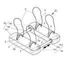
以下、本発明の第1乃至第3の実施形態について図面を参照して説明する。図1及び図2(a)、(b)は、第1の実施形態に係る歩行運動用具1を示す。この歩行運動用具1は、左右一対のパッド2と、各パッド2に設けられる固定部材3と、パッド2同士を連結する連結機構4と、各パッド2に取り付けられる手持ちロープ5とを備えている。この歩行運動用具1は、ユーザが後述のように装着することで、ユーザの歩行可能な方向を横方向に制限するようなものである。   Hereinafter, first to third embodiments of the present invention will be described with reference to the drawings. FIG.1 and FIG.2 (a), (b) shows the walking exercise tool 1 which concerns on 1st Embodiment. The walking exercise tool 1 includes a pair of left and right pads 2, a fixing member 3 provided on each pad 2, a coupling mechanism 4 that couples the pads 2, and a hand-held rope 5 that is attached to each pad 2. . This walking exercise tool 1 is such that the user can wear it as described later, thereby restricting the direction in which the user can walk to the lateral direction.

パッド2は、上面にユーザの足裏が片足ずつ載せられる足置部2aを有しており、下面が床又は地面と接触する接触面であるものである。各パッド2の接触面側には、連結機構4の一端が固定される溝部2bが形成されている。このパッド2は、本実施形態においてはスポンジ部材で形成されており、ユーザが例えば素足を載せたときの感触が良いように、また、ユーザが歩行運動中に転倒したときにも、ユーザが怪我をしにくいように構成されている。パッド2の材質はこれに限らず、他の種々の材質を用いて形成されていてもよい。   The pad 2 has a foot placement portion 2a on which the user's sole is placed on the upper surface one by one, and the lower surface is a contact surface in contact with the floor or the ground. On the contact surface side of each pad 2, a groove 2b to which one end of the coupling mechanism 4 is fixed is formed. The pad 2 is formed of a sponge member in the present embodiment so that the user can be injured even when the user falls, for example, when the user falls down during walking motion so that the user feels good when placing a bare foot. It is configured so that it is difficult to perform. The material of the pad 2 is not limited to this, and may be formed using other various materials.

固定部材3は、その両端が各パッド2の上面に植設されて設けられている。固定部材3は、ユーザの足が足置部2aに載せられたときには、その足の甲を上面から巻着するようにしてその足を固定するように構成されている。本実施形態において、固定部材3としては布やゴム等のベルトが用いられるが、例えばマジックテープ(登録商標)等を用いて、ユーザが足を足置部2aに載せたときに固定部材3の長さを調節しながらその足を固定可能に構成してもよい。また、いわゆる草履の鼻緒のようにパッド2に植設され、ユーザの足指間にその一部をはさむようにすることでユーザの足をパッドに固定可能に構成されていてもよい。なお、固定部材3がパッド2に植設される部位にはプラスチック等の補強部材が埋め込まれていてもよく、補強部材を設けることで固定部材3に力が加えられたときにもパッド2から固定部材3が抜ける等の不具合の発生を防止することが可能である。   The both ends of the fixing member 3 are provided on the upper surface of each pad 2. When the user's foot is placed on the footrest portion 2a, the fixing member 3 is configured to fix the foot so that the back of the foot is wound from the upper surface. In the present embodiment, a belt such as cloth or rubber is used as the fixing member 3, but when the user places his / her foot on the footrest 2 a using, for example, Velcro (registered trademark) or the like, You may comprise so that the leg | foot can be fixed, adjusting length. Moreover, it may be comprised so that a user's foot | toe can be fixed to a pad by being planted by the pad 2 like the so-called sandals of a sandals, and inserting the part between user's toes | fingers. Note that a reinforcing member such as plastic may be embedded in a portion where the fixing member 3 is implanted in the pad 2, and even when a force is applied to the fixing member 3 by providing the reinforcing member, It is possible to prevent problems such as the fixing member 3 coming off.

図3は、連結機構4を示す。連結機構4は、ガイド部材41とスライド部材42とを有している。ガイド部材41は、本実施形態において、図に示されるように、断面が下底が短い台形形状であり、その下面が開放された薄板状のレール形状のものである。ガイド部材41の長手方向の一端には、断面方向に立設してストッパ部41aが形成されており、他端は開放端とされている。このガイド部材41は、1個の連結機構4に2個用いられるものであり、長手方向を横方向として、各パッド2につき1個ずつ、開放端が左右で対向するようにパッド2の溝部2bに固定される。   FIG. 3 shows the coupling mechanism 4. The coupling mechanism 4 includes a guide member 41 and a slide member 42. In the present embodiment, as shown in the drawing, the guide member 41 has a trapezoidal shape with a short bottom and a thin rail shape with a lower surface opened. At one end in the longitudinal direction of the guide member 41, a stopper portion 41a is formed standing in the cross-sectional direction, and the other end is an open end. Two guide members 41 are used for one coupling mechanism 4, and the groove portion 2 b of the pad 2 is arranged so that the open end is opposed to the left and right, one for each pad 2 with the longitudinal direction as the lateral direction. Fixed to.

スライド部材42は、本実施形態においては、ガイド部材41のレール形状の内側断面と略相似形で、大きさがわずかに小さい、台形形状の断面を有する棒状である。このスライド部材42は、連結機構4に1本用いられるものであり、長さは、後述する歩行運動に必要な長さに設定される。このスライド部材42は、図に示されるように、両端がそれぞれガイド部材41の内側に挿入された状態となるように配される。ここで、スライド部材42は、断面形状の大きさがガイド部材41よりもわずかに小さいことから、ガイド部材41に遊嵌された状態となる。これにより、スライド部材42とガイド部材41の両部材が、図3の矢印で示される方向に互いに摺動自在となる。つまり、ガイド部材41とスライド部材42とが互いに摺動自在に挿通して連結され、その長さ方向両端長が伸縮自在となるように連結機構4が構成される。   In this embodiment, the slide member 42 has a bar shape having a trapezoidal cross section that is substantially similar to the rail-shaped inner cross section of the guide member 41 and slightly smaller in size. One slide member 42 is used for the coupling mechanism 4, and the length is set to a length necessary for the walking motion described later. As shown in the figure, the slide member 42 is disposed so that both ends are inserted into the guide member 41. Here, since the size of the cross-sectional shape is slightly smaller than that of the guide member 41, the slide member 42 is loosely fitted to the guide member 41. As a result, both the slide member 42 and the guide member 41 are slidable with respect to each other in the direction indicated by the arrow in FIG. That is, the connecting mechanism 4 is configured such that the guide member 41 and the slide member 42 are slidably inserted into and connected to each other, and the lengths at both ends in the length direction are extendable.

そして、上述のように、連結機構4の一端であるガイド部材41が一対のパッド2の一方の溝部2bに取り付けられ、他端であるガイド部材41がこのパッド2の他方の溝部2bに取り付けられている。このように、連結機構4は一対のパッド2間に跨設されることで、上述のように連結機構4が伸縮することでこれらパッド2間の距離が遠近する方向に移動可能に、パッド2同士を連結している。なお、ガイド部材41及びスライド部材42の断面形状等はこれに限らず、他の多角形等種々の形状とすることが可能である。   As described above, the guide member 41 that is one end of the coupling mechanism 4 is attached to one groove 2b of the pair of pads 2, and the guide member 41 that is the other end is attached to the other groove 2b of the pad 2. ing. As described above, the coupling mechanism 4 is straddled between the pair of pads 2 so that the coupling mechanism 4 expands and contracts as described above so that the distance between the pads 2 can be moved in the direction closer to the pad 2. They are linked together. In addition, the cross-sectional shape etc. of the guide member 41 and the slide member 42 are not restricted to this, It is possible to set it as various shapes, such as another polygon.

手持ちロープ5は、固定部材3のパッド2に取り付けられた基部に両端が植設されるようにパッド2に取り付けられている。この手持ちロープ5は、ユーザが足をパッド2の足置部2aに固定した状態で、ユーザが手で持つことが出来るような長さとされている。   The hand-held rope 5 is attached to the pad 2 so that both ends are implanted in the base part attached to the pad 2 of the fixing member 3. The hand-held rope 5 has such a length that the user can hold it with his / her hand in a state where his / her foot is fixed to the footrest 2 a of the pad 2.

この歩行運動用具1は、ユーザの足が固定部材3により足置部2aに固定された状態で、パッド2が移動可能である方向にユーザの足が動かされることによって、ユーザが床又は地面上を横方向に歩行運動できるように構成されている。上述のように、左右一対のパッド2は2個の連結機構4がその間に跨設されることで、連結機構4のガイド部材41とスライド部材42とが摺動して互いの距離が横方向(図1の矢印方向)にのみ遠近する方向に移動可能に連結されている。このため、ユーザは、足を足置部2aに固定してこの歩行運動用具1を装着すると、パッド2が移動可能な横方向にのみ足を動かすことができる状態となる。これにより、ユーザは、足を横方向に動かすことで横方向にのみ床又は地面上を歩行運動(横歩き)可能となる。   In this walking exercise tool 1, when the user's foot is moved in a direction in which the pad 2 can be moved in a state where the user's foot is fixed to the footrest 2 a by the fixing member 3, the user can It is configured to be able to walk in the horizontal direction. As described above, the pair of left and right pads 2 has the two connecting mechanisms 4 straddled between them, so that the guide member 41 and the slide member 42 of the connecting mechanism 4 slide and the distance between them is lateral. It is connected so as to be movable only in the direction (arrow direction in FIG. 1). For this reason, if a user fixes a foot | leg on the footrest part 2a and wears this walking exercise tool 1, it will be in the state which can move a leg only to the horizontal direction which the pad 2 can move. Thereby, the user can walk (sidewalk) on the floor or the ground only in the horizontal direction by moving his / her foot in the horizontal direction.

この横歩きは、ユーザが左右いずれかの進行方向側の足を進行方向側に移動させたのち、反対側の足を進行方向側の足に引きつけるような動作を繰り返すことにより行われ、うまく歩行するためにはこつが必要となるものである。先ず、ユーザの姿勢が、このユーザの体重が進行方向と反対側のパッド2に片寄って掛かる(重心が進行方向と反対側のパッド2上にある)ような状態とされる。そして、ユーザの進行方向側の足が進行方向側に動かされ、ガイド部材41とスライド部材42とが上述のように摺動して連結機構4が長手方向に伸びることで、図4(a)及び(b)に示されるように、進行方向側のパッド2が移動してパッド2間の距離が遠くなる。次に、進行方向側のパッド2の位置を保持したまま、ユーザの姿勢が変化されて、重心が進行方向側のパッド2上となるように重心移動が行われる。そして、その状態でユーザの反対側の足が進行方向側の足に引きつけられ、ガイド部材41とスライド部材42とが摺動して連結機構4が長手方向に縮み、反対側のパッド2が進行方向側のパッド2に近づく方向に移動する。その後、再び、ユーザの姿勢が変更されて重心がこの反対側のパッド2上にある状態で、ユーザの進行方向側の足が移動されて進行方向側のパッド2が移動される。以後、上記の動作が順に繰り返して行われることで、ユーザは、横方向に床又は地面上を横歩きすることができる。   This sidewalk is performed by moving the user's left or right foot in the direction of travel to the direction of travel, and then repeating the action of attracting the opposite foot to the foot in the direction of travel. In order to do that, you need some tricks. First, the user's posture is such that the weight of the user leans on the pad 2 opposite to the traveling direction (the center of gravity is on the pad 2 opposite to the traveling direction). Then, the user's foot in the traveling direction is moved toward the traveling direction, the guide member 41 and the slide member 42 slide as described above, and the coupling mechanism 4 extends in the longitudinal direction. And as shown in (b), the pad 2 on the traveling direction side moves, and the distance between the pads 2 increases. Next, while maintaining the position of the pad 2 on the traveling direction side, the posture of the user is changed, and the center of gravity is moved so that the center of gravity is on the pad 2 on the traveling direction side. In this state, the foot opposite to the user is attracted to the foot on the traveling direction side, the guide member 41 and the slide member 42 slide, the connecting mechanism 4 contracts in the longitudinal direction, and the pad 2 on the opposite side proceeds. It moves in a direction approaching the pad 2 on the direction side. Thereafter, the user's posture is changed again, and the foot on the traveling direction side of the user is moved so that the pad 2 on the traveling direction side is moved while the center of gravity is on the pad 2 on the opposite side. Thereafter, the above operations are sequentially repeated, so that the user can walk sideways on the floor or the ground in the lateral direction.

なお、この横歩きは、ガイド部材41の長さに応じた所定の歩幅以内の歩幅で行われればよい。本実施形態において、ガイド部材41にはストッパ部41aが形成されているので、上述のように歩行運動が繰り返されてガイド部材41とスライド部材42とが互いに摺動を繰り返しても、スライド部材42の端部はストッパ部41aを超えてガイド部材41から突出してしまうことがないようにされている。つまり、連結機構4は、所定の長さの範囲内で伸縮を繰り返したときに、一方のガイド部材41からスライド部材42が抜脱してしまうことがないように構成されている。   The side walk may be performed at a step within a predetermined step according to the length of the guide member 41. In the present embodiment, since the guide member 41 is formed with the stopper portion 41a, even if the walking motion is repeated as described above and the guide member 41 and the slide member 42 repeatedly slide with each other, the slide member 42 is provided. These end portions are not projected from the guide member 41 beyond the stopper portion 41a. That is, the coupling mechanism 4 is configured so that the slide member 42 does not come out of one guide member 41 when the expansion and contraction is repeated within a predetermined length range.

ここで、ユーザは、各パッド2に取り付けられている手持ちロープ5を保持しながら上述のように横歩きしてもよい。ユーザは、手持ちロープ5を用いることで、足の動作にあわせて体の重心のバランスを容易にとることが可能となり、横歩き中に転倒しにくくなる。これにより、横歩きを継続して行うことが容易に可能となる。   Here, the user may walk sideways as described above while holding the hand-held rope 5 attached to each pad 2. By using the hand-held rope 5, the user can easily balance the center of gravity of the body in accordance with the movement of the foot, and it is difficult for the user to fall while walking sideways. As a result, it is possible to easily perform the sidewalk continuously.

上述のように、ユーザは、この歩行運動用具1を装着すると、パッド2同士の距離が遠近する方向である横方向にのみしか歩行することができなくなる。このため、ユーザは、普段行われることが少ない横歩きを、足を例えば前後方向等に動かしてしまうことなく、確実に継続して行うことができるようになる。また、この横歩きは、普段とは異なる歩行動作であり、筋力やバランス感覚向上等のトレーニングに効果的な動作である一方、上述のようにこつが必要な歩行運動であり、ユーザは面白みを感じながら行うことができるものである。このため、ユーザは面白みを感じて楽しみながら、上述のようなトレーニングを行うことが可能となる。   As described above, when the user wears the walking exercise tool 1, the user can walk only in the lateral direction, which is the direction in which the distance between the pads 2 is closer. For this reason, the user can reliably and continuously perform the sidewalk that is not often performed without moving the foot in the front-rear direction or the like. In addition, this sidewalk is a walking action different from usual, and it is an effective action for training such as improving muscle strength and sense of balance. It can be done while feeling. For this reason, the user can perform the above-described training while enjoying and enjoying the fun.

また、この歩行運動用具1は、例えば運動会等の競技で、歩行運動用具1を装着したユーザ同士で横歩き競走を行う等の用途に用いることが可能である。歩行運動用具1を用いなければユーザは足を自由に動かすことが可能であるため、ユーザは自らの意思で足を動かす方向を横方向に制限することになる。この状態ではユーザが時には所定の進行方向以外に足を動かしてしまうなど競走に公正さを欠く場合がある。しかし、この歩行運動用具1を用いることで、ユーザは上述のように横方向にのみしか足を移動できなくなるため、競走を公正に実施することが容易に可能となる。また、歩行運動用具1を用いることで、上述のように横歩きがこつが必要なものとなるので、ユーザがより楽しみながら競走を行うことが可能となる。   Further, the walking exercise tool 1 can be used for applications such as a sidewalk race between users wearing the walking exercise tool 1 in a competition such as an athletic meet. If the user does not use the walking exercise tool 1, the user can freely move his / her foot. Therefore, the user restricts the direction in which the user moves his / her foot to the lateral direction. In this state, the user sometimes lacks fairness in the race, such as moving his / her foot in a direction other than the predetermined traveling direction. However, by using this walking exercise tool 1, the user can move his / her legs only in the lateral direction as described above, so that it is possible to easily perform the race. Further, by using the walking exercise tool 1, sidewalking is necessary as described above, so that it is possible for the user to perform a race while having more enjoyment.

図5、図6(a)、(b)、(c)、図7(a)、(b)は、本発明の第2の実施形態に係る歩行運動用具11を示す。以下の各実施形態において、上述の実施形態と同様の機能、形状のものは同一の符号を付し、上述の実施形態と相違する部分についてのみ説明する。この歩行運動用具11は、上述の第1の実施形態とは、左右一対のパッド2を連結する連結機構14の構成が異なるものである。   5, FIG. 6 (a), (b), (c), FIG. 7 (a), (b) shows the walking exercise tool 11 according to the second embodiment of the present invention. In each of the following embodiments, the same functions and shapes as those of the above-described embodiment are denoted by the same reference numerals, and only different portions from the above-described embodiment will be described. This walking exercise tool 11 is different from the above-described first embodiment in the configuration of a connecting mechanism 14 that connects a pair of left and right pads 2.

図8は、連結機構14を示す。本実施形態において、連結機構14は2個用いられている。それぞれの連結機構14は、ガイド部材としての筒状部材141とスライド部材としての棒状部材142とを有している。この連結機構14は、筒状部材141と棒状部材142とが互いに摺動自在に挿通して連結されて、その長さ方向両端長が伸縮自在となるように構成されているものである。   FIG. 8 shows the coupling mechanism 14. In the present embodiment, two coupling mechanisms 14 are used. Each coupling mechanism 14 has a cylindrical member 141 as a guide member and a rod-like member 142 as a slide member. The connecting mechanism 14 is configured such that a cylindrical member 141 and a rod-like member 142 are slidably inserted into each other and connected to each other so that lengths at both ends in the length direction can be expanded and contracted.

筒状部材141は、内部の断面が略円形であるシリンダ形状であり、一端には内径が小さい貫通孔を有する抜止部141aが形成されている。この筒状部材141は、それぞれの連結機構14につき2個ずつ用いられるものであり、長手方向を横方向として、各パッド2にそれぞれ一個ずつ、抜止部141aが左右対向するように固定される。本実施形態においては、筒状部材141は一対のパッド2の側面に抜止部141aが露出するように、各パッド2の内部に埋設されて固定されている。   The cylindrical member 141 has a cylindrical shape with a substantially circular inner cross section, and a retaining portion 141a having a through hole with a small inner diameter is formed at one end. Two cylindrical members 141 are used for each coupling mechanism 14, and are fixed to the respective pads 2 so that the retaining portions 141 a are opposed to the left and right, respectively, with the longitudinal direction being the lateral direction. In the present embodiment, the cylindrical member 141 is embedded and fixed inside each pad 2 such that the retaining portion 141 a is exposed on the side surfaces of the pair of pads 2.

棒状部材142は略円形の断面を有するものであり、それぞれの連結機構14につき1個ずつ用いられている。この棒状部材142は、外径が筒状部材141の抜止部141aの内径よりも小さく、図に示されるように、棒状部材142の両端がそれぞれの筒状部材141内となるようにして配される。つまり、棒状部材142は、筒状部材141間に跨り、筒状部材141内に摺動自在に挿通されており、筒状部材141と棒状部材142とが互いに摺動することで、連結機構14の長さ方向両端長が伸縮自在となっている。また、棒状部材142の両端部には、外径が抜止部141aの内径よりも大きく、筒状部材141の内径よりも小さい抜止突起142aが設けられている。これにより、棒状部材142は、連結機構14の長手方向の長さが長くなる方向に摺動しても、抜止突起142aと抜止部141aとが当接するとそれ以上摺動不可となり、棒状部材142が筒状部材141から抜脱されることがないように構成されている。   The rod-shaped member 142 has a substantially circular cross section, and one rod member 142 is used for each coupling mechanism 14. The rod-shaped member 142 is arranged such that the outer diameter is smaller than the inner diameter of the retaining portion 141a of the cylindrical member 141, and as shown in the figure, both ends of the rod-shaped member 142 are within the respective cylindrical members 141. The That is, the rod-shaped member 142 is straddled between the cylindrical members 141, and is slidably inserted into the cylindrical member 141. The cylindrical member 141 and the rod-shaped member 142 slide with each other, so that the coupling mechanism 14 Both lengths in the length direction are extendable. Further, at both end portions of the rod-shaped member 142, retaining protrusions 142a having an outer diameter larger than the inner diameter of the retaining portion 141a and smaller than the inner diameter of the tubular member 141 are provided. As a result, even if the rod-like member 142 slides in the direction in which the longitudinal length of the coupling mechanism 14 increases, the rod-like member 142 cannot slide any more when the retaining protrusion 142a and the retaining portion 141a come into contact with each other. Is configured so as not to be removed from the tubular member 141.

なお、図示は省くが、この連結機構14は、例えば、棒状部材142の端部の抜止突起142aの形状と抜止部141aの貫通孔部分の形状が、棒状部材142を抜止部141aに対して軸周りに回転させたときに所定位置で合致するような複雑な形状とされている。これにより、抜止突起142aは抜止部141aと当接せず、棒状部材142は筒状部材141から抜差可能となる。つまり、筒状部材141と棒状部材142とが連結されていない状態から、抜止突起142aの形状を抜止部141aの貫通孔部分の形状と合わせることで、筒状部材141に棒状部材142を挿通させて、連結機構14をスムーズ且つ容易に組み立てることができる。なお、連結機構14を組み立てた後、抜止部141aの貫通孔部分のうち、棒状部材142が筒状部材141と摺動するのに必要な棒状部材の断面部位以外の部分は、樹脂プレート等を接着又は螺結すること等によって覆われるような構成としてもよい。   Although not shown in the drawings, the connecting mechanism 14 is configured such that, for example, the shape of the retaining protrusion 142a at the end of the rod-shaped member 142 and the shape of the through-hole portion of the retaining portion 141a are such that the rod-shaped member 142 is pivoted with respect to the retaining portion 141a. It has a complicated shape that matches at a predetermined position when rotated around. As a result, the retaining protrusion 142a does not contact the retaining portion 141a, and the rod-shaped member 142 can be removed from the tubular member 141. That is, from the state where the tubular member 141 and the rod-shaped member 142 are not coupled, the rod-shaped member 142 is inserted into the tubular member 141 by matching the shape of the retaining protrusion 142a with the shape of the through-hole portion of the retaining portion 141a. Thus, the coupling mechanism 14 can be assembled smoothly and easily. In addition, after assembling the coupling mechanism 14, a portion other than the cross-sectional portion of the rod-shaped member necessary for the rod-shaped member 142 to slide with the cylindrical member 141 out of the through-hole portion of the retaining portion 141 a is a resin plate or the like. It is good also as a structure covered by adhesion | attachment or screwing.

本実施形態においても、上述の実施形態と同様に、ユーザの足が固定部材3により足置部2aに固定された状態で、パッド2が移動可能である横方向にユーザの足が動かされることによって、ユーザは床又は地面上を横方向に横歩きすることが可能である。この歩行運動用具11を用いることで、上述と同様に、ユーザは、普段行われることが少ない横歩きを、足を例えば前後方向等に動かしてしまうことなく、確実に継続して行うことができるようになる。   Also in this embodiment, the user's foot is moved in the lateral direction in which the pad 2 is movable in a state where the user's foot is fixed to the footrest portion 2a by the fixing member 3 in the same manner as the above-described embodiment. Thus, the user can walk sideways on the floor or the ground. By using this walking exercise tool 11, as described above, the user can reliably and continuously perform a lateral walk that is not often performed without moving the foot in the front-rear direction or the like. It becomes like this.

図9及び図10(a)、(b)は、本発明の第3の実施形態に係る歩行運動用具21を示す。この歩行運動用具21は、上述の第2の実施形態に係る歩行運動用具11とは、パッド2が前後方向に長い形状であり、1つのパッド2につき2個の足置部2aが設けられている点が異なるものである。つまり、この歩行運動用具21は、各足置部2aにそれぞれの片足を固定した二人のユーザが同時に横歩き可能となるように構成されている。なお、本実施形態において、固定部材3及び手持ちロープ5は、設けられた足置部2aの位置に応じて2個ずつ各パッド2に配設されている。なお、足置部2aは、1つのパッド2につき2個ずつに限らず、さらに多くの個数の足置部2aが各パッド2に設けられているようなものであってもよく、複数人のユーザが同時に横歩き可能となるように構成してもよい。   9 and 10 (a) and 10 (b) show a walking exercise tool 21 according to a third embodiment of the present invention. The walking exercise tool 21 is different from the walking exercise tool 11 according to the second embodiment described above in that the pad 2 has a shape that is long in the front-rear direction, and two footrest portions 2 a are provided for each pad 2. Is different. That is, the walking exercise tool 21 is configured such that two users who have their respective legs fixed to each footrest 2a can walk sideways at the same time. In the present embodiment, two fixing members 3 and hand-held ropes 5 are disposed on each pad 2 in accordance with the position of the provided footrest portion 2a. Note that the number of foot placement portions 2a is not limited to two for each pad 2, and a larger number of foot placement portions 2a may be provided on each pad 2. You may comprise so that a user can walk sideways simultaneously.

本実施形態においても、上述の実施形態と同様にして、歩行運動用具21を装着したユーザは横歩きを行う。このとき、複数人で同時に横歩きを行うことから、うまく歩行運動を継続させるためにはユーザ同士の協力が必要となる。これにより、ユーザ同士で息を合わせるような面白みがある歩行運動を行うことが可能になる。また、例えば幼児教育や初等教育用途では、この歩行運動用具21を用いて横歩きを行うことにより、上述のようにトレーニングを楽しく行うことができるとともに、他者との協調性の大切さ等ついて楽しく学習することが可能となる。   Also in the present embodiment, the user wearing the walking exercise tool 21 performs a side walk in the same manner as in the above-described embodiment. At this time, since a plurality of people walk sideways at the same time, it is necessary to cooperate with each other in order to successfully continue the walking motion. As a result, it is possible to perform a walking exercise that is interesting so that the users can breathe together. Also, for example, in early childhood education or primary education, by using this walking exercise tool 21 to perform sidewalks, training can be performed happily as described above, and the importance of cooperation with others, etc. It becomes possible to learn happily.

ここで、図示はしないが、上述の各実施形態に係る歩行運動用具1,11,21は、例えば児童又は幼児等がユーザであるとき等、パッド2に生物や乗り物等を模した装飾部を設けた構成としてもよい。例えば、左右一対のパッド2に、蟹の脚や目等を模した形状の成形物である装飾部を装設することにより、歩行運動用具1の外観を、蟹を想起させる形状となるように装飾してもよい。このように、例えばパッド2に蟹を模した装飾部を設けて歩行運動用具1,11,21を装飾すると、横歩きの動作が、ユーザ等に蟹の動く動作を想起させるものとなり、ユーザがより楽しみながら歩行運動を行うことが可能となる。   Here, although not shown in the drawings, the walking exercise tools 1, 11 and 21 according to each of the above-described embodiments have a decorative part imitating a living thing or a vehicle on the pad 2 when, for example, a child or an infant is a user. It is good also as a provided structure. For example, the appearance of the walking exercise tool 1 is reminiscent of a heel by installing a decorative part, which is a molded product simulating the legs and eyes of the heel, on the pair of left and right pads 2. It may be decorated. In this way, for example, when a decoration part imitating a heel is provided on the pad 2 to decorate the walking exercise tools 1, 11 and 21, the sidewalking action reminds the user of the movement of the heel, and the user It is possible to perform walking exercise while having more fun.

なお、本発明は上記実施形態の構成に限定されるものではなく、発明の範囲を変更しない範囲で適宜に種々の変形が可能である。例えば、手持ちロープ5は必ず必要なものではなく、例えば用途や対象となるユーザ等に応じて手持ちロープ5を有さない構成としてもよい。また、パッド2同士を連結する連結機構4,14の数は上述のように1個又は2個に限らず、さらに多くてもよい。連結機構4,14は、側面に設けられるものでなくとも、各パッド2の上面や下面に設けた取り付け部材等を用いて固定されるようなものであってもよい。   In addition, this invention is not limited to the structure of the said embodiment, A various deformation | transformation is suitably possible in the range which does not change the range of invention. For example, the hand-held rope 5 is not necessarily required. For example, the hand-held rope 5 may be configured not to have the hand-held rope 5 in accordance with the intended use or the target user. Further, the number of connecting mechanisms 4 and 14 for connecting the pads 2 to each other is not limited to one or two as described above, and may be larger. The coupling mechanisms 4 and 14 may not be provided on the side surfaces, but may be fixed using attachment members or the like provided on the upper and lower surfaces of each pad 2.

また、連結機構4,14は、上述の各実施形態の他にも種々の構成とすることが可能である。例えば、複数の互いに異なる内径及び外径を有する筒状部材141を内径及び外径が大きい順に互いに同軸に重ね合わせたような構成としてもよい。このとき、外形の最も大きい筒状部材141を一端とし、他端を外形の最も小さい筒状部材141として、両端を一対のパッド2にそれぞれ固定する。このような構成であっても、筒状部材141が互いに摺動することで、連結機構4,14は長手方向に伸縮自在となり、上述の各実施形態と同様にパッド2同士を連結することが可能である。   Further, the coupling mechanisms 4 and 14 can have various configurations in addition to the above-described embodiments. For example, it is good also as a structure which piled up the cylindrical member 141 which has several mutually different internal diameters and outer diameters coaxially mutually in order with a large internal diameter and external diameter. At this time, the cylindrical member 141 having the largest outer shape is used as one end and the other end is used as the cylindrical member 141 having the smallest outer shape, and both ends are fixed to the pair of pads 2. Even in such a configuration, when the cylindrical members 141 slide relative to each other, the coupling mechanisms 4 and 14 can expand and contract in the longitudinal direction, and the pads 2 can be coupled to each other as in the above-described embodiments. Is possible.

さらに、連結機構4,14は、球やころを用いた直動軸受けのような摺動機構を有していてもよい。例えば、上述の第1の実施形態において、ガイド部材41がその内面に露出した複数の球を有しており、スライド部材42が、その複数の球の上を転がるようにしてガイド部材41と互いに摺動し、連結機構4の長さ方向両端長が伸縮自在となるような構成とされていてもよい。このような摺動機構を用いることで、スライド部材42とガイド部材41が互いに摺動するときの抵抗を低減することができるようになるため、ユーザは、よりスムーズに上述のような横歩きを行うことが可能となる。   Further, the coupling mechanisms 4 and 14 may have a sliding mechanism such as a linear motion bearing using balls or rollers. For example, in the first embodiment described above, the guide member 41 has a plurality of spheres exposed on the inner surface thereof, and the slide member 42 rolls on the spheres so as to roll on the guide member 41 and each other. The sliding mechanism may be configured such that both end lengths in the length direction of the coupling mechanism 4 are extendable. By using such a sliding mechanism, the resistance when the slide member 42 and the guide member 41 slide with each other can be reduced, so that the user can walk more smoothly as described above. Can be done.

上記のほかにも、連結機構を、例えば、各パッド2から他方のパッド2に向けて横方向に連結プレートを設けてパッド2同士を連結するような構成とすることができる。この連結機構は、一方の連結プレートが、横方向に長い長穴状のスロットを有しており、他方の連結プレートが、スロット幅よりわずかに小さい外径であり、このスロット内に緩挿される棒状部材を有しているものである。連結機構は、両連結プレートはスロット内面をこの棒状部材が摺動可能となるように組み合わされており、パッド2同士を連結する。このような連結機構を用いたときにも、一方の連結プレートのスロット内面を、他方の連結プレートの棒状部材が摺動することで、パッド2間の距離が横方向に遠近する方向にパッド2が移動可能となる。このような歩行運動用具を用いたときも、上述と同様に、ユーザは横歩きを行うことが可能となる。   In addition to the above, for example, the connection mechanism can be configured to connect the pads 2 by providing a connection plate in the lateral direction from each pad 2 toward the other pad 2. In this connection mechanism, one connection plate has a slot in the shape of a long hole in the lateral direction, and the other connection plate has an outer diameter slightly smaller than the slot width, and is loosely inserted into this slot. It has a rod-shaped member. In the connecting mechanism, both connecting plates are combined on the inner surface of the slot so that the rod-like member can slide, and connect the pads 2 to each other. Even when such a coupling mechanism is used, the pad 2 in the direction in which the distance between the pads 2 is reduced in the lateral direction by sliding the rod-shaped member of the other coupling plate on the inner surface of the slot of the one coupling plate. Can be moved. Even when such a walking exercise tool is used, the user can walk sideways as described above.

本発明の第1の実施形態に係る歩行運動用具の斜視図。The perspective view of the walking exercise tool which concerns on the 1st Embodiment of this invention. (a)は同上歩行運動用具の上面図、(b)はその側面図。(A) is a top view of the same walking exercise tool, (b) is a side view thereof. 同上歩行運動用具の連結機構の斜視図。The perspective view of the connection mechanism of a walking exercise tool same as the above. (a)は同上歩行運動用具の歩行動作時を示す上面図、(b)はその側面図。(A) is a top view showing the walking motion of the same walking exercise tool, (b) is a side view thereof. 本発明の第2の実施形態に係る歩行運動用具の斜視図。The perspective view of the walking exercise tool which concerns on the 2nd Embodiment of this invention. (a)は同上歩行運動用具の側面図、(b)はその上面図、(c)は(b)のA−A線断面図。(A) is a side view of the walking exercise tool same as above, (b) is a top view thereof, (c) is a cross-sectional view taken along line AA of (b). (a)は同上歩行運動用具の歩行動作時を示す上面図、(b)は(a)のA−A線断面図。(A) is a top view which shows the time of the walking operation of a walking exercise tool same as the above, (b) is the sectional view on the AA line of (a). 同上歩行運動用具の連結機構の部分断面図。The fragmentary sectional view of the connection mechanism of a walking exercise tool same as the above. 本発明の第3の実施形態に係る歩行運動用具の斜視図。The perspective view of the walking exercise tool which concerns on the 3rd Embodiment of this invention. (a)は同上歩行運動用具の側面図、(b)はその上面図。(A) is a side view of the walking exercise tool, and (b) is a top view thereof.

符号の説明Explanation of symbols

1 歩行運動用具
2 パッド
2a 足置部
3 固定部材
4 連結機構
41 ガイド部材
42 スライド部材
DESCRIPTION OF SYMBOLS 1 Walking exercise tool 2 Pad 2a Footrest part 3 Fixing member 4 Connection mechanism 41 Guide member 42 Slide member

Claims (2)

上面にユーザの足裏が片足ずつ載せられる足置部を有し、下面が床又は地面と接触する左右一対のパッドと、
前記パッドのそれぞれに設けられ、前記足置部に載せられたユーザの足を固定するための固定部材と、
前記一対のパッド間に跨設され、該一対のパッド間の距離が遠近する方向に摺動移動可能なパッド同士を連結する連結機構と、を備え、
ユーザの足が前記固定部材により前記足置部に固定された状態で、前記パッドが摺動移動可能な方向に前記固定部材で固定されたユーザの足が動かされる範囲内でのみユーザが床又は地面上を横方向に歩行運動できるようにしたことを特徴とする歩行運動用具。
A pair of left and right pads that have a footrest on which the sole of the user's sole is placed on the upper surface, and the lower surface contacts the floor or the ground
A fixing member provided on each of the pads, for fixing a user's foot placed on the footrest;
A coupling mechanism that spans between the pair of pads and that couples the pads that are slidable in a direction in which the distance between the pair of pads is closer;
In a state where the user's foot is fixed to the footrest by the fixing member, the user can move the floor or the user only within the range in which the user's foot fixed by the fixing member is moved in a direction in which the pad can slide. A walking exercise tool characterized by being able to walk on the ground laterally.
前記連結機構は、スライド部材とガイド部材とを有し、これら両部材が互いに摺動自在に連結されて、その長さ方向両端長が伸縮自在となるように、その一端が前記一対のパッドの一方に取り付けられ、他端が同パッドの他方に取り付けられていることを特徴とする請求項1記載の歩行運動用具。
The coupling mechanism includes a slide member and a guide member, and both ends of the pair are slidably coupled to each other so that one end of the pair of pads is stretchable so that both lengths in the longitudinal direction can be expanded and contracted. The walking exercise tool according to claim 1, wherein the walking exercise tool is attached to one side and the other end is attached to the other side of the pad.
JP2005139240A 2005-05-12 2005-05-12 Walking exercise equipment Active JP4706038B2 (en)

Priority Applications (1)

Application Number Priority Date Filing Date Title
JP2005139240A JP4706038B2 (en) 2005-05-12 2005-05-12 Walking exercise equipment

Applications Claiming Priority (1)

Application Number Priority Date Filing Date Title
JP2005139240A JP4706038B2 (en) 2005-05-12 2005-05-12 Walking exercise equipment

Publications (2)

Publication Number Publication Date
JP2006314482A JP2006314482A (en) 2006-11-24
JP4706038B2 true JP4706038B2 (en) 2011-06-22

Family

ID=37535693

Family Applications (1)

Application Number Title Priority Date Filing Date
JP2005139240A Active JP4706038B2 (en) 2005-05-12 2005-05-12 Walking exercise equipment

Country Status (1)

Country Link
JP (1) JP4706038B2 (en)

Citations (3)

* Cited by examiner, † Cited by third party
Publication number Priority date Publication date Assignee Title
JPS58171168U (en) * 1982-05-12 1983-11-15 埼玉化工株式会社 exercise equipment
JPH02135055U (en) * 1989-04-17 1990-11-09
JP2001333999A (en) * 2000-03-22 2001-12-04 Shinwa Kogyo Kk Toughening device for the lower half of body

Patent Citations (3)

* Cited by examiner, † Cited by third party
Publication number Priority date Publication date Assignee Title
JPS58171168U (en) * 1982-05-12 1983-11-15 埼玉化工株式会社 exercise equipment
JPH02135055U (en) * 1989-04-17 1990-11-09
JP2001333999A (en) * 2000-03-22 2001-12-04 Shinwa Kogyo Kk Toughening device for the lower half of body

Also Published As

Publication number Publication date
JP2006314482A (en) 2006-11-24

Similar Documents

Publication Publication Date Title
TWI523670B (en) Exercise device with varied gait movements
US4253661A (en) Leg exercising device
US9387363B1 (en) Ball and board balance training device
CN100467006C (en) Proprioceptive/kinesthetic apparatus and method
JPH07298903A (en) Bottom of shoes
EP1964485A1 (en) Proprioceptive/kinesthetic apparatus and method
JP4706038B2 (en) Walking exercise equipment
US20050272578A1 (en) Technique-development and strength-training device for skaters and method of use
JP2023052803A (en) Walking training instrument
CN2574726Y (en) Face mask structure for swimming
WO2023090259A1 (en) Sports equipment
US20060123662A1 (en) Health shoes
CN201036673Y (en) Children heart and intelligent sport training implement
CN103623553A (en) Fitness ball
JP6120293B2 (en) Hip joint exercise aid
JPS62481Y2 (en)
KR200237972Y1 (en) Jumping leg with spring
JP5336677B1 (en) Training footwear and training method using the same
TWM516999U (en) Belt body structure of treadmill
JP3180145U (en) Knee muscle strengthening device
JP3195700U (en) Balance beam
KR101033663B1 (en) Soles for Increasing Energy Consumption and Shoes Therefor
JP3188549U (en) Stepping health device
KR101138716B1 (en) Soles for Increasing Energy Consumption and Shoes Therefor
TWM528769U (en) Lower limbs and brain training device

Legal Events

Date Code Title Description
A621 Written request for application examination

Free format text: JAPANESE INTERMEDIATE CODE: A621

Effective date: 20080509

A977 Report on retrieval

Free format text: JAPANESE INTERMEDIATE CODE: A971007

Effective date: 20100827

A131 Notification of reasons for refusal

Free format text: JAPANESE INTERMEDIATE CODE: A131

Effective date: 20100907

A521 Written amendment

Free format text: JAPANESE INTERMEDIATE CODE: A523

Effective date: 20101108

RD02 Notification of acceptance of power of attorney

Free format text: JAPANESE INTERMEDIATE CODE: A7422

Effective date: 20101108

A01 Written decision to grant a patent or to grant a registration (utility model)

Free format text: JAPANESE INTERMEDIATE CODE: A01

Effective date: 20101227

A61 First payment of annual fees (during grant procedure)

Free format text: JAPANESE INTERMEDIATE CODE: A61

Effective date: 20110124

A61 First payment of annual fees (during grant procedure)

Free format text: JAPANESE INTERMEDIATE CODE: A61

Effective date: 20110221

FPAY Renewal fee payment (event date is renewal date of database)

Free format text: PAYMENT UNTIL: 20140325

Year of fee payment: 3

FPAY Renewal fee payment (event date is renewal date of database)

Free format text: PAYMENT UNTIL: 20140325

Year of fee payment: 3

R250 Receipt of annual fees

Free format text: JAPANESE INTERMEDIATE CODE: R250

R250 Receipt of annual fees

Free format text: JAPANESE INTERMEDIATE CODE: R250