JP4704983B2 - Shifting operation structure of walking type work machine - Google Patents
Shifting operation structure of walking type work machine Download PDFInfo
- Publication number
- JP4704983B2 JP4704983B2 JP2006240297A JP2006240297A JP4704983B2 JP 4704983 B2 JP4704983 B2 JP 4704983B2 JP 2006240297 A JP2006240297 A JP 2006240297A JP 2006240297 A JP2006240297 A JP 2006240297A JP 4704983 B2 JP4704983 B2 JP 4704983B2
- Authority
- JP
- Japan
- Prior art keywords
- shaft
- clutch
- shift
- speed change
- reverse
- Prior art date
- Legal status (The legal status is an assumption and is not a legal conclusion. Google has not performed a legal analysis and makes no representation as to the accuracy of the status listed.)
- Active
Links
Images


Landscapes
- Arrangement Of Transmissions (AREA)
- Arrangement And Driving Of Transmission Devices (AREA)
- Gear-Shifting Mechanisms (AREA)
Description
本発明は、ミッションケースの上部から機体後方に向けて操縦ハンドルを延出するとともに、ミッションケースに備えられたPTO軸から取出した動力で駆動される作業装置を機体後部に連結可能に構成した歩行型作業機の変速操作構造に関する。 The present invention is a walking in which a steering handle is extended from the upper part of a mission case toward the rear of the fuselage, and a work device driven by power taken out from a PTO shaft provided in the mission case is connectable to the rear part of the fuselage. The present invention relates to a shift operation structure of a type work machine.
上記歩行型作業機の変速操作構造としては、例えば、特許文献1に示されているように、ミッションケースに支持された走行変速用の変速操作軸を、PTOクラッチレバーのクラッチ入り位置への操作に連動して牽制部材を前方に移動させて、ミッションケースに支持された走行変速用の変速操作軸に係合させ、PTOクラッチ入り状態で後進が行われることを牽制阻止するよう構成したものが知られている。
上記変速操作構造においては、ミッションケースに備えたPTO軸からの動力を作業装置に伝達し、作業装置に備えたPTOクラッチを作業装置に備えたPTOクラッチレバーで入り切り操作する構造であるために、ミッションケースに装備された牽制部材の作動機構と作業装置側に装備された作業クラッチレバーとを操作ワイヤで連係する構造となり、後進牽制手段に多くの部材を必要としてコスト高になるものであった。また、PTOクラッチレバーと牽制部材とを連係する操作ワイヤに伸びが発生すると牽制機能が適切に発揮されなくなるおそれがあり、メンテナンスを充分行う必要もあった。 In the above speed change operation structure, the power from the PTO shaft provided in the transmission case is transmitted to the work device, and the PTO clutch provided in the work device is operated with the PTO clutch lever provided in the work device. The operation mechanism of the check member provided in the mission case and the work clutch lever provided on the work device side are linked by an operation wire, which requires many members for the reverse check means and increases the cost. . In addition, if the operation wire that links the PTO clutch lever and the restraining member is stretched, the restraining function may not be properly exhibited, and it is necessary to perform sufficient maintenance.
本発明は、このような点に着目してなされたものであって、簡単な構造で後進牽制を的確に行うことができる変速操作構造を提供することを目的としている。 The present invention has been made paying attention to such a point, and an object of the present invention is to provide a speed change operation structure capable of accurately performing the reverse check with a simple structure.
第1の発明は、ミッションケースの上部から機体後方に向けて操縦ハンドルを延出した自走式本機の後部に、ミッションケースに備えられたPTO軸から取出した動力で駆動される作業装置を連結可能に構成した歩行型作業機の変速操作構造において、
前記PTO軸への動力断続を行うPTOクラッチを前記ミッションケースに装備するとともに、走行変速を行う複数の変速操作軸と前記PTOクラッチを入り切り操作するクラッチ操作軸とをミッションケースに支持し、後進変速を行う前記変速操作軸と前記クラッチ操作軸との間に、PTOクラッチ入り状態で変速操作軸が後進位置に移動した状態が現出されるのを係合阻止する後進牽制手段を装備し、
前記変速操作軸を軸心方向にシフト操作可能に構成するとともに、前記クラッチ操作軸を回動操作可能に構成し、前記クラッチ操作軸に一体連結した牽制部材で後進変速を行う変速操作軸の後進位置への移動を係合阻止するように前記後進牽制手段を構成し、
前記変速操作軸の後方下方に前記クラッチ操作軸を配備し、前記変速操作軸のケース外方突出部位に、変速レバーによって選択係合される係合部材を設けて、この係合部材に係合部を形成するとともに、前記クラッチ操作軸のケース外方突出部位に、このクラッチ操作軸から上方に延出する状態で前記牽制部材を連結固定し、
前記クラッチ操作軸がクラッチ入り位置に回動操作されることで、前記牽制部材の上端部が前方に揺動して後進変速を行う前記変速操作軸の係合部材の係合部に変速シフト方向と交差する後方側から係合し、この変速操作軸が後進位置へシフト移動するのを阻止するよう構成してあることを特徴とする。
In the first aspect of the present invention, a working device driven by power extracted from a PTO shaft provided in the transmission case is provided at the rear of the self-propelled main unit extending the steering handle from the upper part of the transmission case toward the rear of the aircraft. In the shift operation structure of the walking work machine configured to be connectable,
The transmission case is equipped with a PTO clutch for intermittently driving power to the PTO shaft, and a plurality of speed change operation shafts for running and shifting, and a clutch operation shaft for turning on and off the PTO clutch are supported on the transmission case, and the reverse speed change. wherein during the speed change operation shaft and the clutch operating shaft, equipped with a reverse restrain means for engaging prevent the shift operation shaft in PTO clutch engaging state while moving to the rear Susumui location is to appear to perform,
The shift operation shaft is configured to be shiftable in the axial direction, the clutch operation shaft is configured to be rotatable, and the reverse operation of the shift operation shaft is performed by a check member integrally connected to the clutch operation shaft. The reverse check means is configured to prevent engagement to a position,
The clutch operating shaft is disposed below and below the speed change operating shaft, and an engaging member that is selectively engaged by a speed change lever is provided at a case outward projecting portion of the speed changing operation shaft. Forming the portion, and connecting and fixing the check member to the case outward projecting portion of the clutch operating shaft in a state of extending upward from the clutch operating shaft,
When the clutch operating shaft is rotated to the clutch engagement position, the upper end portion of the restraining member swings forward to perform the reverse shift, and the engaging portion of the engaging member of the speed change operating shaft shifts in the shift shift direction. The shift operation shaft is engaged with the rear side that intersects with the rear side to prevent the shift operation shaft from shifting to the reverse position .
上記構成によると、ミッションケースに備えた変速操作軸とクラッチ操作軸とを近くに配備することができるので、変速操作軸とクラッチ操作軸の間に装備する後進牽制手段に複雑な連係構造は不要であり、例えば、クラッチ操作軸に牽制部材を連結固定し、この牽制部材を変速操作軸、あるいは、変速操作軸に連結されている部材に係合させるような簡単な構造で、変速操作軸が後進位置へ移動するのを阻止することが可能となる。 According to the above configuration, it is possible to deploy the speed change operation shaft and a clutch operating shaft provided in the transmission case near the complex linkage structure to the reverse restraining means to equip between speed change operation shaft and the clutch operation shaft is not required For example, with a simple structure in which a check member is connected and fixed to the clutch operation shaft, and this check member is engaged with the speed change operation shaft or a member connected to the speed change operation shaft, the speed change operation shaft is It is possible to prevent movement to the reverse position.
従って、的確な後進牽制が可能な変速操作構造を、部品少なく簡単な構造で構成することができる。 Accordingly, specific and precise reverse restraining capable speed change operation structure can be composed of components less simple structure.
上記構成によると、後進変速を行う変速操作軸とクラッチ操作軸の操作方向が相違しているので、クラッチ操作軸をクラッチ入り位置に操作することで、牽制部材を変速操作軸あるいはこれに連結した部材に移動方向と交差する方向から係合させることができ、係合牽制を簡単に行うことができる。According to the above configuration, since the operation direction of the shift operation shaft for performing the reverse shift and the clutch operation shaft are different, the check member is connected to the shift operation shaft or to this by operating the clutch operation shaft to the clutch engagement position. The member can be engaged from the direction intersecting the moving direction, and the engagement check can be easily performed.
上記構成によると、変速操作のために変速操作軸に装備される係合部材を、牽制部材に係合される部材として有効に利用することができる。According to the above configuration, the engaging member provided on the speed change operation shaft for the speed change operation can be effectively used as the member engaged with the check member.
第2の発明は、上記第1の発明において、
前記係合部の後端が前記クラッチ操作軸の軸心よりも後側に位置するように、前記係合部材に前記係合部を形成してあるものである。
According to a second invention, in the first invention,
The engagement portion is formed on the engagement member so that the rear end of the engagement portion is located on the rear side of the axis of the clutch operation shaft .
第3の発明は、上記第1又は第2の発明において、
前記牽制部材を上下2位置に選択移動させてボルトで前記クラッチ操作軸に締め付け固定することで、前記牽制部材を下方の牽制解除位置と上方の牽制作用位置とに取付け位置変更可能に構成してあるものである。
第4の発明は、上記第3の発明において、
前記牽制部材に上下に長いダルマ孔を形成するとともに、前記ボルトの頭部に前記ダルマ孔の上下の孔部に嵌入する円形の位置決め座部を形成してあるものである。
According to a third invention, in the first or second invention,
The check member is selectively moved to the upper and lower two positions and fastened and fixed to the clutch operating shaft with a bolt, so that the attachment position of the check member can be changed between a lower check release position and an upper check production position. There is something.
According to a fourth invention, in the third invention,
A long dharma hole is formed in the restraining member in the vertical direction, and a circular positioning seat portion is formed in the head of the bolt to be fitted in the upper and lower hole portions of the dharma hole.
上記構成によると、自走式本機の後部に、薬剤散布装置や播種装置などの、回転作動部が露出していないような駆動型の作業装置を連結する場合には、牽制部材を牽制解除位置に切換えておくことで、PTOクラッチ入り状態でも自由に後進変速して能率的な作業を行うことが可能となる。 According to the above configuration, when connecting a drive-type working device that does not expose the rotating operation part, such as a drug spraying device or a seeding device, to the rear of the self-propelled machine, the check member is released. By switching to the position, it becomes possible to carry out efficient work by freely performing reverse shift even when the PTO clutch is engaged.
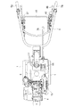
図1および図2に、自走式本機Aの後部に駆動型の作業装置の一例であるロータリ耕耘装置Bを連結して耕耘機仕様に構成した歩行型作業機の全体側面および全体平面がぞれぞれ示されている。この歩行型作業機の自走式本機Aは、左右の車輪1が軸支されたミッションケース2からエンジン支持フレーム3が前向き片持ち状に延出され、このエンジン支持フレーム3に横軸型のエンジン4が搭載連結されるとともに、ミッションケース2の上部に、前後に向き変更可能な操縦ハンドル5が後向き片持ち状に延出された構造を備えている。なお、この歩行型作業機においては、基本的にはエンジン4の在る側が機体前方、その逆向きが機体後方とされるものであり、以後の説明における方向の記述は上記した基本の前後方向に基づくことにする。
1 and 2, the entire side surface and the entire plane of the walking type working machine constructed by connecting the rotary tiller B, which is an example of the driving type working device, to the rear part of the self-propelled main machine A and having the tiller specifications are shown. Each one is shown. The self-propelled main machine A of this walking type working machine has an
図3に示すように、前記エンジン4は、シリンダ部軸心が後傾斜されて上下に嵩低く構成されたリコイル始動式の空冷ガソリンエンジンが利用されており、このエンジン4とミッションケース2との間の空隙を埋めるように燃料タンク6(図2参照)が配備されている。
As shown in FIG. 3, the
エンジン4の左側に突出された出力軸11とミッションケース2の上部左側に突出された入力軸12とが、テンションクラッチ式の主クラッチ13を備えたベルト伝動機構14で連動連結されるとともに、このベルト伝動機構14全体が樹脂製のベルトカバー15で囲繞されている。
An
ミッションケース2の後部には各種作業装置を連結する後部ヒッチ7が、また、エンジン支持フレーム3の前端には前部ヒッチ8がそれぞれ備えられており、後部ヒッチ7を介してロータリ耕耘装置Rが連結されている。ミッションケース2の上部右側に突設された後述するPTO軸19から取出された動力が、チェーンケース9を介してロータリ耕耘装置Rに伝達されるようになっている。
A
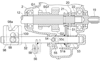
図4〜図7に、ミッションケース2に内装された伝動構造が示されている。ミッションケース2の上部に配備された前記入力軸12の前方にバック軸16が配備されるとともに、このバック軸16の下方に第2軸17が配備され、さらに、入力軸12の下方に位置して第3軸18が配備されている。入力軸12の右端部は、ケース右側面に軸受け貫通支承されたPTO軸19の内端部に同心に軸受け支承され、入力軸12の動力が爪咬合式のPTOクラッチ20を介してPTO軸19に伝達されるようになっている。
4 to 7 show the transmission structure housed in the
PTOクラッチ20は、入力軸12にスライド可能にスプライン外嵌された爪付きのスライドカラー21と、PTO軸19の内端部に一体形成した爪付きのクラッチボス22とで構成されており、スライドカラー21が右方にシフトされてクラッチボス22に爪咬合することで入力軸12からPTO軸19へ動力伝達を行うクラッチ入り状態がもたらされ、スライドカラー21を左方へ後退スライドさせて、図5に示すように爪咬合を解除することで入力軸12からPTO軸19への動力伝達を遮断するクラッチ切り状態がもたらされるようになっている。
The
入力軸12、バック軸16、および、第2軸17との間に、第2軸17を前進2段、後進2段に変速する主変速機構23が介在されており、その変速構造を以下に説明する。
Between the
入力軸12には、小径ギヤG1と大径ギヤG2を備えた第1シフトギヤSG1がシフト可能にスプライン外嵌されるとともに、第2軸17に、前記小径ギヤG1および大径ギヤG2に選択咬合される受動ギヤG3,G4が外嵌固着されている。図5に示すように、第1シフトギヤSG1が中立位置にある時、小径ギヤG1および大径ギヤG2は共に受動ギヤG3,G4から外れ、第1シフトギヤSG1を中立位置から図中右方にシフトして小径ギヤG1を受動ギヤG3に咬合させることで、第2軸17が前進1速で駆動され、第1シフトギヤSG1を中立位置から図中左方にシフトして大径ギヤG2を受動ギヤG4に咬合させることで、第2軸17が前進2速で駆動されるようになっている。
A first shift gear SG1 having a small-diameter gear G1 and a large-diameter gear G2 is fitted on the
バック軸16には、小径ギヤG5と大径ギヤG6を備えた第2シフトギヤSG2がシフト可能にスプライン外嵌されている。第1シフトギヤSG1の大径ギヤG2と第2シフトギヤSG2の大径ギヤG6はそれぞれ広幅に構成され、第1、第2シフトギヤSG1,SG2がどのようにシフトされていても常に咬合され、バック軸16が入力軸12と逆方向に回転駆動されている。図5に示すように、第2シフトギヤSG2が中立位置にある時、小径ギヤG5および大径ギヤG6は共に受動ギヤG3,G4から外れ、第2シフトギヤSG2を中立位置から図中右方にシフトして小径ギヤG5を受動ギヤG3に咬合させることで第2軸17が後進1速で駆動され、第2シフトギヤSG2を中立位置から図中左方にシフトして大径ギヤG6を受動ギヤG4に咬合させることで第2軸17が後進2速で駆動されるようになっている。
A second shift gear SG2 having a small diameter gear G5 and a large diameter gear G6 is fitted on the
第2軸17と第3軸18の間に、第2軸17からの動力を3段に変速する副変速機構24が介在されており、その変速構造を以下に説明する。
第2軸17には、小径ギヤG7、大径ギヤG8、および、小径幅広ギヤG9がそれぞれ遊嵌支持されるとともに、第3軸18には、前記小径ギヤG7、大径ギヤG8、および、小径幅広ギヤG9のそれぞれに常時咬合された受動ギヤG10,G11,G12が装着されている。受動ギヤG10,G11が第3軸18に固定されているのに対して、受動ギヤG12は第3軸18に遊嵌され、かつ、受動ギヤG12には出力スプロケット25が一体に連設されている。小径幅広ギヤG9には大径ギヤG13が一体連結されており、この大径ギヤG13が第3軸18に一体形成されたピニオンギヤG14に常時咬合されている。
Between the
A small-diameter gear G7, a large-diameter gear G8, and a small-diameter wide gear G9 are loosely supported on the
第2軸17は筒軸状に構成されて、その左端から変速操作軸26が軸心方向にシフト操作可能に挿入されるとともに、変速操作軸26の内端部には第2軸17の内周に摺接するカラー部材28が連結されている。このカラー部材28には半径方向に出退変位可能、かつ、内装バネ29で突出付勢された伝動キー27が組み込まれており、変速操作軸26が軸心方向にシフトされることによって伝動キー27が、小径ギヤG7、大径ギヤG8、小径幅広ギヤG9のいずれか一つに内周から係合されるようになっている。
The
変速操作軸26が最も内方に押し込みシフトされた状態では、伝動キー27が小径ギヤG7の内周に係合されて第2軸17と小径ギヤG7とが一体化される。これによって、第2軸17の動力が小径ギヤG7と受動ギヤG10を介して第3軸18に伝達される。第3軸18に伝達された動力は、ピニオンギヤG14および大径ギヤG13を介して小径幅広ギヤG9に減速伝達され、さらに、小径幅広ギヤG9および受動ギヤG12を介して減速されて出力スプロケット25が低速で駆動される状態となる。
In a state in which the speed
図5に示すように、変速操作軸26が左右中間位置にスライドされた状態では、伝動キー27が大径ギヤG8の内周に係合されて第2軸17と大径ギヤG8とが一体化される。これによって、第2軸17の動力が大径ギヤG8と受動ギヤG11を介して第3軸18に伝達される。第3軸18に伝達された動力は、ピニオンギヤG14および大径ギヤG13を介して小径幅広ギヤG9に減速伝達され、さらに、小径幅広ギヤG9および受動ギヤG12を介して減速されて出力スプロケット25が中速で駆動される状態となる。
As shown in FIG. 5, when the speed
変速操作軸26が最も外方に引き出しシフトされた状態では、伝動キー27が小径幅広ギヤG9の内周に係合されて第2軸17と小径幅広ギヤG9とが一体化される。これによって、第2軸17の動力が直接に小径幅広ギヤG9を介して受動ギヤG12に減速伝達され、出力スプロケット25が高速で駆動される状態がもたらされる。
In a state in which the speed
このように、副変速機構24は、主変速機構23で前進2段・後進2段に変速されて第2軸17に伝達された動力を更に3段に変速して出力スプロケット25に伝達するよう構成されているのである。
In this way, the
出力スプロケット25から取り出された変速動力は、ミッションケース2の下部に支架された左右の車軸29に以下のように伝達される。
図4,図6に示すように、左右の車軸29は同心に対向配備されるとともに、両車軸29に亘って中間支軸30が挿入されている。両車軸29の突合せ部に亘って遊転自在に外嵌装着された受動スプロケット32と前記出力スプロケット25とがチェーン33を介して巻掛け連動されている。
The speed change power taken out from the
As shown in FIGS. 4 and 6, the left and
受動スプロケット32と左右の車軸29とはボール式のサイドクラッチ34を介して連動連結されており、両サイドクラッチ34を共に入れることで左右の車軸29を一体駆動して直進走行を行い、一方のサイドクラッチ34を切って一方の車軸29を遊転状態にすることで片輪駆動による機体操向を行うことができるよう構成されている。
The
サイドクラッチ34は、受動スプロケット32から左右に延出されたクラッチボス35と、クラッチボス35の周方向複数箇所に係合支持された伝動ボール36と、クラッチボス35の外周にシフト可能に外嵌装着された操作カラー37と、操作カラー37を軸心方向外方に付勢シフトするクラッチバネ38とで構成されている。通常時には、図6中の左半部に示されるように、クラッチバネ38で操作カラー37が外方にシフトされることで、伝動ボール36が操作カラー37の内周で半径方向内方に押し込められ、伝動ボール36がクラッチボス35と車軸29の外周に形成された伝動溝29aに亘って係合された状態となり、受動スプロケット32から車軸29への伝動が行われるクラッチ入り状態がもたらされる。図6中の右半部に示されるように、操作カラー37をクラッチバネ38に抗して内方にシフトすると、操作カラー37の内周による伝動ボール36の押し込みが解除されて、伝動ボール36が操作カラー37の内周空間39に退避可能となり、伝動ボール36が車軸29の伝動溝29aから逃げ出すことで、受動スプロケット32から車軸29への伝動を遮断するクラッチ切り状態がもたらされる。
The side clutch 34 has a
次に、前記主クラッチ13、PTOクラッチ20、主変速機構23、副変速機構24、および、サイドクラッチ34の各操作構造について説明する。
〔主クラッチ操作構造〕
図11,図12に示すように、操縦ハンドル5の左側に、ブラケット41を介して主クラッチレバー42が横向き支点a周りに前後揺動可能に配備されており、主クラッチレバー42の基端から延出された作動部材43に湾曲リンク40の一端が枢支連結され、湾曲リンク44の他端と主クラッチ13のテンションアーム13aとが操作ワイヤ44およびストローク吸収用のバネ45(図3参照)を介して連動連結されている。
Next, the operation structures of the main clutch 13, the PTO clutch 20, the
[Main clutch operation structure]
As shown in FIGS. 11 and 12, a main
図12に示すように、主クラッチレバー42を、死点DPを大きく後方に越えたクラッチ切り位置OFFに操作することで、操作ワイヤ44を弛めてテンションアーム13aを自重で下方揺動させ、主クラッチレバー42を、死点DPを少し前方に越えたクラッチ入り位置ONに操作することで、操作ワイヤ44を後方に引いて、テンションアーム13aを上方揺動させるようになっている。
As shown in FIG. 12, by operating the main
前記ブラケット41には、操縦ハンドル5における左側のグリップ部5gを握った手の親指で押し下げ操作可能な補助クラッチレバー46が横向き支点b周りに揺動可能かつ復帰上昇可能に配備されている。この補助クラッチレバー46は、押し下げ操作するたびに、主クラッチレバー42を現在の操作位置から逆位置に強制揺動させることができるように、主クラッチレバー42に連係されており、両手で操縦ハンドル5を握ったままでも、左手の指操作で主クラッチ13の入り切りを行うことができるようになっている。
The
操縦ハンドル5の左右に設けられたブラケット41,47に亘ってアーチ形の牽制レバー48が装備されている。この牽制レバー48は、主クラッチレバー42がクラッチ入り位置ONにある状態で前方に揺動操作されると、主クラッチレバー42をクラッチ切り位置OFFに強制揺動させるよう構成されており、操縦作業者が動かない状態で機体が後進した際に、牽制レバー48が操縦作業者に押されて相対的に前方に揺動されることで、自動的に主クラッチ13が切られて後進が停止するようになっている。
An arch-shaped
〔PTOクラッチ操作構造〕
図8に示すように、PTOクラッチ20におけるスライドカラー21に係合されたシフトフォーク51が、ミッションケース2に貫通支架されたクラッチ操作軸52にスライド移動可能に外嵌装着されている。クラッチ操作軸52は、回動可能かつケース外方への移動を阻止された状態で支障されており、シフトフォーク51はクラッチ操作軸52に外嵌装着されたバネ53によってクラッチ切り方向(図8では左方)にスライド付勢されるとともに、シフトフォーク51を備えた基端ボス51aの左端が、クラッチ操作軸52に打ち込み貫通された操作ピン54に受け止め支持されている。
[PTO clutch operation structure]
As shown in FIG. 8, the
前記基端ボス部51aの左端には傾斜カム部55が形成されており、クラッチ操作軸52が所定の方向へ回動操作されると、操作ピン54が同方向に回動して傾斜カム部55を接当押圧することで、シフトフォーク51がバネ53に抗してクラッチ入り方向(図8では右方)にシフト作動されてサイドクラッチ20が入れられ、クラッチ操作軸52への前記所定方向への回動操作が解除されると、バネ53の復元力で基端ボス部51aがクラッチ切り方向にシフトされながら傾斜カム部55で操作ピン54を押圧することで、クラッチ操作軸52が逆方向に回動されるようになっている。
An
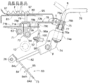
クラッチ操作軸52のケース外突出部には操作アーム56が固着されており、この操作アーム56が、操縦ハンドル5における右側に前後揺動可能に軸支されたPTOクラッチレバー57に操作ワイヤ58を介して連動連結されている。PTOクラッチレバー57は、死点DPを後方に大きく越えたクラッチ切り位置OFFと、死点DPを前方に少し越えた位置にクラッチ入り位置ONとに任意に切換え操作して、その操作位置に保持しておくことができるようになっている。PTOクラッチレバー57を大きく後方に操作すると操作ワイヤ58が弛められ、バネ付勢力でスライド付勢される傾斜カム部55が操作ピン54を押圧することで、図10(イ)に示すように、クラッチ操作軸52が時計方向に回動されてクラッチ切り位置OFFに保持される。PTOクラッチレバー57を大きく前方に操作すると操作ワイヤ58が引かれ、図10(ロ)に示すように、クラッチ操作軸52が反時計方向に回動されてクラッチ切り位置OFFに切換えられる。
An
〔主・副変速機構操作構造〕
図7に示すように、主変速機構23において前進2段の変速を行う第1シフトギヤSG1と、後進2段の変速を行う第2シフトギヤSG2とは、それぞれ第1シフトフォーク61と第2シフトフォーク62に係合支持されており、第1シフトフォーク61を固着した前進変速用の変速操作軸63と、第2シフトフォーク62を固着した後進変速用の変速操作軸64がそれぞれミッションケース2の左側壁に左右シフト可能に突出支承されている。図10に示すように、後進変速用の変速操作軸64が入力軸12の上方に配備されるとともに、前進変速用の変速操作軸63がバック軸16の上方に配備され、第1シフトフォーク61と第2シフトフォーク62とが側面からみて交差して延出されている。
[Main / sub transmission mechanism operation structure]
As shown in FIG. 7, in the
図7に示すように、ミッションケース2の左側壁には、バネ65で付勢された2組のデテントボール66が装備されている。デテントボール66は、各変速操作軸63,64の外周にシフトピッチに対応した間隔で形成された3つの環状溝67のいずれか一つに付勢係合されることで、各変速操作軸63,64を高低2段の変速位置F1,F2,R1,R2と中立位置Nに安定保持する。バネ65およびデテントボール66は、ケース側壁の内面に開放して成形された凹部68にケース内方から組み込まれ、ケース内方からボルト連結される共通の当て板69によって凹部68を塞ぐことでバネ65およびデテントボール66の抜け出しが阻止されるようになっている。
As shown in FIG. 7, two sets of
主変速用の各変速操作軸63,64における外方突出部位にはブロック状の係合部材71,72が固着されるとともに、両係合部材71,72が前後に近接配備されている。副変速用の変速操作軸26の外方突出部位にはカム板73が後下り傾斜姿勢で連結されている。
Block-like engaging
図3,図17〜図21に示すように、ミッションケース2における左横外側の上部後端近くに、横向き支点p周りに回動可能に変速作動部材74が枢着され、この変速作動部材74に備えられた縦向きのボス部74aに、縦向き軸心q周りに回動のみ自在に回動部材75が支持されるとともに、この回動部材75およびボス部74aに変速レバー76の基端縦軸部76aが挿入連結されている。変速レバー76の基端縦軸部76aは回動部材75に対して上下スライド可能に支持されるとともに、内装したバネ77によって下方にスライド付勢されており、基端縦軸部76aが下方スライドされると基端縦軸部76aの外周に形成されたセレーション部76bが回動部材75のセレーション孔75aに嵌合されて、変速レバー76と回動部材75とが縦向き軸心q周りに一体回動可能となり、基端縦軸部76aをバネ77に抗して上方に引き上げることで、基端縦軸部76aのセレーション部76bが回動部材75のセレーション孔75aから上方に抜け外れ、変速レバー76を縦向き軸心q周りに旋回させて操縦ハンドル5と同じ向きに変更することが可能となる。
As shown in FIG. 3 and FIG. 17 to FIG. 21, a
前記回動部材75には横向き支点t周りに上下に自由揺動可能に板金構造の主変速操作部材78が枢支連結されている。この主変速操作部材78の前後3箇所から係合片78a,78b,78c片が下向きに折り曲げ突設されており、これら係合片78a,78b,78cが、前記係合部材71,72に選択係合されるようになっている。係合部材71,72には係合片78a,78b,78cの前後方向への移動を許容し、係合片78a,78b,78cを左右移動不能に係合する係合溝71a,72aがそれぞれ形成されるとともに、係合部材71,72には、自重で下方揺動する主変速操作部材78の係合片78a,78b,78cを受け止める平坦な案内辺71b,72bが連設されており、両変速操作軸63,64が共に中立位置にある時に、両係合部材71,72の係合溝71a,72aが前後に合致して、係合片78a,78b,78cの前後への通過移動が可能となる。
A main
主変速操作部材78からは上方に向けてゲージピン79が立設されており、ミッションケース2の上部に固定配備された変速案内板80の案内溝81、および、さらにその上に固定配備された変速表示板95の案内溝96にゲージピン79が挿通されている。
A
前記変速作動部材74と副変速用の変速操作軸26とがカム機構83を介して連動連結されている。このカム機構83は、変速操作軸26に連結された前記カム板73と、変速作動部材74の下端部から延出された1本の変速操作ピン82とで構成されており、カム板73の遊端側は、ミッションケース2に連結固定されたガイド部材85に左右移動可能に案内係合されて、変速操作軸26の軸心方向シフトにかかわらずカム板73が常に一定の姿勢に維持されるようになっている。
The speed
図14〜図16に示すように、前記カム板73には前後方向に長い階段状のカム溝84が形成されており、このカム溝84に変速操作ピン82が係入されている。従って、変速レバー76の上下揺動操作によって変速操作ピン82が横向き支点p周りに揺動すると、カム溝84の案内作用によってカム板73が相対的に左右に移動されて、変速操作軸26が左右にシフト操作されるようになっている。
As shown in FIGS. 14 to 16, the
具体的には、図14に示すように、変速レバー76が下方域に操作されると、変速操作ピン82がカム溝84の上部ガイド部84uに位置し、変速操作軸26が大きく押し込みシフトされて副変速機構24が「低速」に切換えられる。図15に示すように、変速レバー76が上下中間域に操作されると、変速操作ピン82がカム溝84の中間ガイド部84mに位置し、変速操作軸26が左方に引き出しシフトされて副変速機構24が「中速」に切換えられる。更に、図16に示すように、変速レバー76が上方域に操作されると、変速操作ピン82がカム溝84の下部ガイド部84dに位置し、変速操作軸26が更に左方に引き出しシフトされて副変速機構24が「高速」に切換えられる。
Specifically, as shown in FIG. 14, when the
図17に示すように、変速レバー76を左右中央の中立位置で最下方の変速域に操作すると、副変速機構24が「低速」に切換えられた状態で、最前方の係合片78aが前進変速用の係合部材71に選択係合されることになり、この状態で変速レバー76を左右に揺動操作することで、選択係合した変速操作軸63をシフト操作して、前進1速F1と前進2速F2の変速を行うことができる。
As shown in FIG. 17, when the
図18に示すように、変速レバー76を左右中央の中立位置に戻して1段上方に操作すると、副変速機構24が「低速」に維持された状態で、前後中間の係合片78bが後進変速用の係合部材72に選択係合されることになり、この状態で変速レバー76を左右に揺動操作することで、選択係合した変速操作軸64をシフト操作して、後進1速R1と後進2速R2の変速を行うことができる。
As shown in FIG. 18, when the
図19に示すように、変速レバー76を左右中央の中立位置に戻して更に1段上方に操作すると、副変速機構24が「中速」に切換えられた状態で、前後中間の係合片78bが前進変速用の係合部材71に選択係合されることになり、この状態で変速レバー76を左右に揺動操作することで、選択係合した変速操作軸63をシフト操作して、前進3速F3と前進4速F4の変速を行うことができる。
As shown in FIG. 19, when the
図20に示すように、変速レバー76を左右中央の中立位置に戻して更に1段上方に操作すると、副変速機構24が「中速」に維持された状態で、最後方の係合片78bが後進変速用の係合部材72に選択係合されることになり、この状態で変速レバー76を左右に揺動操作することで、選択係合した変速操作軸64をシフト操作して、後進3速R3と後進4速R4の変速を行うことができる。
As shown in FIG. 20, when the
図21に示すように、変速レバー76を左右中央の中立位置に戻して最上方の操作域に操作すると、副変速機構24が「高速」に切換えられた状態で、最後方の係合片78cが前進変速用の係合部材71に選択係合されることになり、この状態で変速レバー76を左右に揺動操作することで、選択係合した変速操作軸63をシフト操作して、前進5速F5と前進6速F6の変速を行うことができる。
As shown in FIG. 21, when the
すなわち、この実施例では、前進2段・後進2段の変速が可能な主変速機構23と3段の変速が可能な副変速機構24を組合わせることで、全体として前進6段・後進4段の多段変速を行うよう構成されているのである。
That is, in this embodiment, the
図17〜図21,図24に示すように、前記変速表示板95に形成された案内溝96の横側には山形に突出する表示部97が設けられている。この表示部97の後向き斜面rに機体後方から読み取り可能に変速段が表示されるとともに、表示部97の前向き斜面fに機体前方から読み取り可能に変速段が表示され、操縦ハンドル5および変速レバー76を後向き延出した基本状態ではゲージピン79の位置を表示部97の後向き斜面rの表示に対比させることで変速位置を認識することができ、操縦ハンドル5および変速レバー76を前向き反転した逆向き状態ではゲージピン79の位置を表示部97の前向き斜面fの表示に対比させることで変速位置を認識することができるようになっている。
As shown in FIGS. 17 to 21 and 24, a
〔サイドクラッチ操作構造〕
図4,図6に示すように、左右のサイドクラッチ34における操作カラー37は、ミッションケース2の内部に前後向き支点s周りに揺動可能に支持されたシフトフォーク87に係合され、左右の各シフトフォーク87の上端部が、ミッションケース2における左右側面の上下中間部に装備されたクラッチ操作軸88に操作ロッド89を介してリンク連動されている。クラッチ操作軸88の外部に設けた操作アーム90と操縦ハンドル5の左右に装備されたグリップレバー91とがワイヤ連係されており、操縦ハンドル5のグリップ部5gとグリップレバー91とを共握り操作することで、握り込んだ側のサイドクラッチ34を切り操作するよう構成されている。
[Side clutch operation structure]
As shown in FIGS. 4 and 6, the operating
この歩行型作業機には、ロータリ耕耘装置Bを駆動した状態で後進することを牽制阻止する以下のような構造の後進牽制手段が備えられている。 This walking work machine is provided with a reverse check means having the following structure for preventing the reverse drive while the rotary tiller B is driven.
つまり、図10に示すように、主変速において後進変速を行う変速操作軸64の係合部材72の後側に縦壁状のリブ72cが一体形成されている。図9に示すように、変速操作軸64の後方下方に配備された前記クラッチ操作軸52は操作アーム56の連結位置よりも外方に延長され、その延長部外周に切削形成した扁平面52aに、鋼板製の牽制部材98がボルト99によって締め付け固定されている。この牽制部材98の取付け孔100は上下に長いダルマ孔に形成されるとともに、前記ボルト99の頭部には取付け孔100に嵌入する円形の位置決め座部99aが形成されており、ボルト99を弛めて位置決め座部99aを取付け孔100から外すことで、牽制部材98を上下2位置に選択移動させて締め付け固定することができるようになっている。
That is, as shown in FIG. 10, the vertical wall-shaped
図10に示すように、牽制部材98を上方の牽制作用位置に固定した状態では、牽制部材98の回動軌跡と前記リブ72cのシフト移動軌跡とが干渉することになり、図10(イ)に示すように、クラッチ操作軸52がクラッチ切り位置OFFに回動された状態では、牽制部材98がリブ72cから後方に外れ、後進変速用の変速操作軸64を任意にシフト操作することができる状態となる。つまり、PTOクラッチ切り状態では後進変速を任意に行うことが可能となる。
As shown in FIG. 10, when the
図10(ロ)に示すように、変速操作軸64が中立状態でクラッチ操作軸52がクラッチ入り位置ONに回動されると、牽制部材98の上端に形成した係合凹部98aが係合部材72のリブ72cに係合し、変速操作軸64を中立位置から変速位置へシフト操作することが阻止される。つまり、PTOクラッチ入り状態では後進変速を行うことが不能となるのである。逆に、変速操作軸64が中立から内方あるいは外方にシフトされて後進変速が選択されている状態では、クラッチ切り位置OFFのクラッチ操作軸52をクラッチ入り位置ONに回動操作しようとしても、牽制部材98の先端部がリブ72cの端縁に接当してクラッチ入り位置ONへの回動が阻止されるのである。つまり、PTOクラッチ入り状態で後進する状態が現出することが阻止されるのである。
As shown in FIG. 10 (b), when the
牽制部材98を下方の牽制解除位置に固定すると、牽制部材98の回動軌跡がリブ72cから下方に外れた位置に移動し、クラッチ操作軸52と共に牽制部材98が回動されても、牽制部材98がリブ72cに干渉することはなく、PTOクラッチ20の入り切りに関係なく後進変速用の変速操作軸64を任意にシフト操作することができる状態となる。
When the restraining
〔他の実施例〕
(1)PTOクラッチ20の操作構造を、図25に示すように構成することもできる。つまり、左右二分割構造に構成されたミッションケース2に前記クラッチ操作軸52が回動およびシフト可能に支持されるとともに、左側のケース側壁の内面に、クラッチ操作軸52を同心状に囲むようにカム部55が一体形成され、クラッチ操作軸52に打ち込まれた前記操作ピン54の両端突出部位がカム部55の内方端部に受け止め支持されている。このカム部55は、図26,図27に示すように、180°位相をずらして2組の台形山部55aと谷部55bが交互に形成されるとともに、台形山部55aの平坦頂部と谷部55bの底面とが傾斜カム面55cでつながれている。従って、操作ピン54の両端突出部位が谷部55bに落ち込む回動位相にあるようにクラッチ操作軸52が回動されていると、クラッチ操作軸52およびシフトフォーク51がクラッチ切り位置に付勢スライドされ、この回動位相からクラッチ操作軸52を強制回動すると、操作ピン54の両端突出部位が傾斜カム面55cにせり上がり移動し、これによってクラッチ操作軸52およびシフトフォーク51がバネ53に抗してクラッチ入り位置に移動される。
[Other Examples]
(1) The operating structure of the PTO clutch 20 can be configured as shown in FIG. In other words, the
(2)前記牽制部材98とリブ72cとを傾斜カムを介して係合させるよう構成し、変速操作軸64が後進位置にある状態でクラッチ操作軸52をクラッチ切り位置OFFからクラッチ入り位置ONに無理に回動操作すると、傾斜カムのカム作用で後進位置にある変速操作軸64が中立に強制シフトされるように構成することもできる。
(2) The
2 ミッションケース
5 操縦ハンドル
19 PTO軸
20 PTOクラッチ
52 クラッチ操作軸
63 変速操作軸
64 変速操作軸
71 係合部材
72 係合部材
72c リブ(係合部)
76 変速レバー
98 牽制部材
99 ボルト
99a 位置決め座部
100 取付け孔(ダルマ孔)
A 自走式本機
R 作業装置(ロータリ耕耘装置)
2
72c rib (engagement part)
76
99 volts
99a Positioning seat
100 Mounting hole (Dharma hole)
A Self-propelled machine R Working device (Rotary tillage device)
Claims (4)
前記PTO軸への動力断続を行うPTOクラッチを前記ミッションケースに装備するとともに、走行変速を行う複数の変速操作軸と前記PTOクラッチを入り切り操作するクラッチ操作軸とをミッションケースに支持し、後進変速を行う前記変速操作軸と前記クラッチ操作軸との間に、PTOクラッチ入り状態で変速操作軸が後進位置に移動した状態が現出されるのを係合阻止する後進牽制手段を装備し、
前記変速操作軸を軸心方向にシフト操作可能に構成するとともに、前記クラッチ操作軸を回動操作可能に構成し、前記クラッチ操作軸に一体連結した牽制部材で後進変速を行う変速操作軸の後進位置への移動を係合阻止するように前記後進牽制手段を構成し、
前記変速操作軸の後方下方に前記クラッチ操作軸を配備し、前記変速操作軸のケース外方突出部位に、変速レバーによって選択係合される係合部材を設けて、この係合部材に係合部を形成するとともに、前記クラッチ操作軸のケース外方突出部位に、このクラッチ操作軸から上方に延出する状態で前記牽制部材を連結固定し、
前記クラッチ操作軸がクラッチ入り位置に回動操作されることで、前記牽制部材の上端部が前方に揺動して後進変速を行う前記変速操作軸の係合部材の係合部に変速シフト方向と交差する後方側から係合し、この変速操作軸が後進位置へシフト移動するのを阻止するよう構成してあることを特徴とする歩行型作業機の変速操作構造。 A walk that is configured to be able to connect a work device driven by power extracted from the PTO shaft provided in the mission case to the rear part of the self-propelled machine that extended the steering handle from the top of the mission case toward the rear of the aircraft In the shift operation structure of the type work machine,
The transmission case is equipped with a PTO clutch for intermittently driving power to the PTO shaft, and a plurality of speed change operation shafts for running and shifting, and a clutch operation shaft for turning on and off the PTO clutch are supported on the transmission case, and the reverse speed change. wherein during the speed change operation shaft and the clutch operating shaft, equipped with a reverse restrain means for engaging prevent the shift operation shaft in PTO clutch engaging state while moving to the rear Susumui location is to appear to perform,
The shift operation shaft is configured to be shiftable in the axial direction, the clutch operation shaft is configured to be rotatable, and the reverse operation of the shift operation shaft is performed by a check member integrally connected to the clutch operation shaft. The reverse check means is configured to prevent engagement to a position,
The clutch operating shaft is disposed below and below the speed change operating shaft, and an engaging member that is selectively engaged by a speed change lever is provided at a case outward projecting portion of the speed changing operation shaft. Forming the portion, and connecting and fixing the check member to the case outward projecting portion of the clutch operating shaft in a state of extending upward from the clutch operating shaft,
When the clutch operating shaft is rotated to the clutch engagement position, the upper end portion of the restraining member swings forward to perform the reverse shift, and the engaging portion of the engaging member of the speed change operating shaft shifts in the shift shift direction. A shift operation structure for a walk-type working machine , wherein the shift operation shaft is engaged from the rear side intersecting with the shaft to prevent the shift operation shaft from shifting to a reverse position .
Priority Applications (1)
| Application Number | Priority Date | Filing Date | Title |
|---|---|---|---|
| JP2006240297A JP4704983B2 (en) | 2006-09-05 | 2006-09-05 | Shifting operation structure of walking type work machine |
Applications Claiming Priority (1)
| Application Number | Priority Date | Filing Date | Title |
|---|---|---|---|
| JP2006240297A JP4704983B2 (en) | 2006-09-05 | 2006-09-05 | Shifting operation structure of walking type work machine |
Publications (2)
| Publication Number | Publication Date |
|---|---|
| JP2008064150A JP2008064150A (en) | 2008-03-21 |
| JP4704983B2 true JP4704983B2 (en) | 2011-06-22 |
Family
ID=39287043
Family Applications (1)
| Application Number | Title | Priority Date | Filing Date |
|---|---|---|---|
| JP2006240297A Active JP4704983B2 (en) | 2006-09-05 | 2006-09-05 | Shifting operation structure of walking type work machine |
Country Status (1)
| Country | Link |
|---|---|
| JP (1) | JP4704983B2 (en) |
Families Citing this family (2)
| Publication number | Priority date | Publication date | Assignee | Title |
|---|---|---|---|---|
| JP6207473B2 (en) * | 2014-06-30 | 2017-10-04 | 株式会社クボタ | Working machine |
| KR101922431B1 (en) | 2017-11-07 | 2018-11-28 | 대한민국 | Gear transmission apparatus and cultivator having the gear transmission apparatus |
Citations (5)
| Publication number | Priority date | Publication date | Assignee | Title |
|---|---|---|---|---|
| JPS53143702U (en) * | 1977-04-20 | 1978-11-13 | ||
| JPS6212542U (en) * | 1985-07-09 | 1987-01-26 | ||
| JPH0163539U (en) * | 1987-10-20 | 1989-04-24 | ||
| JPH10287141A (en) * | 1997-04-14 | 1998-10-27 | Mitsubishi Agricult Mach Co Ltd | Walking type movement agricultural machine |
| JP2001088568A (en) * | 1999-09-20 | 2001-04-03 | Seirei Ind Co Ltd | Pto operating mechanism for controller |
-
2006
- 2006-09-05 JP JP2006240297A patent/JP4704983B2/en active Active
Patent Citations (5)
| Publication number | Priority date | Publication date | Assignee | Title |
|---|---|---|---|---|
| JPS53143702U (en) * | 1977-04-20 | 1978-11-13 | ||
| JPS6212542U (en) * | 1985-07-09 | 1987-01-26 | ||
| JPH0163539U (en) * | 1987-10-20 | 1989-04-24 | ||
| JPH10287141A (en) * | 1997-04-14 | 1998-10-27 | Mitsubishi Agricult Mach Co Ltd | Walking type movement agricultural machine |
| JP2001088568A (en) * | 1999-09-20 | 2001-04-03 | Seirei Ind Co Ltd | Pto operating mechanism for controller |
Also Published As
| Publication number | Publication date |
|---|---|
| JP2008064150A (en) | 2008-03-21 |
Similar Documents
| Publication | Publication Date | Title |
|---|---|---|
| JP4785873B2 (en) | Bicycle shifting hub | |
| JP4362431B2 (en) | Tractor shifting operation structure | |
| JP6374903B2 (en) | Bicycle transmission | |
| JP2010095203A (en) | Electric bicycle | |
| JP6008778B2 (en) | Power transmission device for work vehicle | |
| JP4704983B2 (en) | Shifting operation structure of walking type work machine | |
| JP4773287B2 (en) | Shifting operation structure of walking type work machine | |
| JP4585406B2 (en) | Side clutch switching mechanism of riding type rice transplanter | |
| JP2012066735A (en) | Transplanter | |
| JP4583390B2 (en) | Power transmission device for vehicle | |
| JP4563014B2 (en) | Agricultural machine | |
| JP4450673B2 (en) | Walking type work machine | |
| JP4704966B2 (en) | Shifting structure of work equipment | |
| JP2002362466A (en) | Transmission of powered bicycle | |
| JP2007139170A (en) | Operation structure of work vehicle | |
| JP5030155B2 (en) | Work vehicle | |
| JP5436287B2 (en) | Riding machine | |
| JP2007120770A5 (en) | ||
| JP3644735B2 (en) | Transmission system for riding rice transplanter | |
| TW590944B (en) | Power unit for small-size vehicle | |
| JP4823415B2 (en) | Management machine | |
| JP2009029169A (en) | Working vehicle | |
| JP5063569B2 (en) | Work vehicle | |
| JP5052407B2 (en) | Safety device for walking type management machine | |
| JP4996405B2 (en) | Work vehicle |
Legal Events
| Date | Code | Title | Description |
|---|---|---|---|
| A621 | Written request for application examination |
Free format text: JAPANESE INTERMEDIATE CODE: A621 Effective date: 20080924 |
|
| A977 | Report on retrieval |
Free format text: JAPANESE INTERMEDIATE CODE: A971007 Effective date: 20101028 |
|
| A131 | Notification of reasons for refusal |
Free format text: JAPANESE INTERMEDIATE CODE: A131 Effective date: 20101104 |
|
| A521 | Written amendment |
Free format text: JAPANESE INTERMEDIATE CODE: A523 Effective date: 20101227 |
|
| TRDD | Decision of grant or rejection written | ||
| A01 | Written decision to grant a patent or to grant a registration (utility model) |
Free format text: JAPANESE INTERMEDIATE CODE: A01 Effective date: 20110210 |
|
| A61 | First payment of annual fees (during grant procedure) |
Free format text: JAPANESE INTERMEDIATE CODE: A61 Effective date: 20110310 |
|
| R150 | Certificate of patent or registration of utility model |
Ref document number: 4704983 Country of ref document: JP Free format text: JAPANESE INTERMEDIATE CODE: R150 |