JP4701954B2 - Paper feeding device, paper feeding method, or image forming apparatus - Google Patents
Paper feeding device, paper feeding method, or image forming apparatus Download PDFInfo
- Publication number
- JP4701954B2 JP4701954B2 JP2005275760A JP2005275760A JP4701954B2 JP 4701954 B2 JP4701954 B2 JP 4701954B2 JP 2005275760 A JP2005275760 A JP 2005275760A JP 2005275760 A JP2005275760 A JP 2005275760A JP 4701954 B2 JP4701954 B2 JP 4701954B2
- Authority
- JP
- Japan
- Prior art keywords
- paper
- sheet
- end side
- rear end
- take
- Prior art date
- Legal status (The legal status is an assumption and is not a legal conclusion. Google has not performed a legal analysis and makes no representation as to the accuracy of the status listed.)
- Expired - Fee Related
Links
Images


Description
本発明は、複写機、FAX、プリンタおよび複合機等の画像形成装置で使用される給紙装置、給紙方法、および前記給紙装置を備えた画像形成装置に関し、給紙トレイに積載された用紙束の一番上の用紙を1枚づつ分離して用紙搬送方向下流側に給紙する給紙装置、給紙方法および前記給紙装置を備えた画像形成装置に関する。 The present invention relates to a sheet feeding device, a sheet feeding method, and an image forming apparatus including the sheet feeding device, which are used in an image forming apparatus such as a copying machine, a FAX, a printer, and a multifunction machine. The present invention relates to a sheet feeding device, a sheet feeding method, and an image forming apparatus including the sheet feeding device that separates the top sheet of a sheet bundle one by one and feeds the sheet to the downstream side in the sheet conveyance direction.
画像形成装置の給紙装置は、給紙トレイに積載された用紙束の一番上の用紙を、ピックアップローラにより1枚づつピックアップして給紙路に給紙するように構成されている。前記給紙トレイに載置された用紙間の摩擦抵抗が高いと用紙が重送されてしまうことがある。 The sheet feeding device of the image forming apparatus is configured to pick up the top sheet of the stack of sheets stacked on the sheet feeding tray one by one by a pickup roller and feed it to the sheet feeding path. If the frictional resistance between the sheets placed on the sheet feeding tray is high, the sheets may be double fed.
前記用紙の重送を防止する技術としては、次の文献(1),(2)に記載された技術が従来公知である。
(1)特許文献1(特開2004−210463号公報)
(2)特許文献2(特開2004−244161号公報)
前記特許文献1,2に記載の技術では、ピックアップローラの直後にフィードローラ(給紙ローラ)およびリタードローラを有するさばきローラを設置している。前記従来公知のリタードローラには、トルクリミッタ付きのワンウェイクラッチまたは摩擦ブレーキ等が設けられる。前記フィードローラおよびリタードローラを有するさばきローラは、ピックアップローラから重送された用紙を1枚づつ分離して用紙搬送方向下流側に搬送している。
As a technique for preventing the double feeding of the paper, techniques described in the following documents (1) and (2) are conventionally known.
(1) Patent Document 1 (Japanese Patent Laid-Open No. 2004-210463)
(2) Patent Document 2 (Japanese Patent Laid-Open No. 2004-244161)
In the techniques described in
また、最近のプリンタでは多様な記録材への印刷要求が多く、メールシール紙等の特殊用紙への印刷要求が増加している。前記メールシール紙などの糊付き用紙は普通紙に比較して摩擦係数が高く、重送、ピックアップミス等、給紙時のトラブル発生率が高く、安定した給紙を行うことができなくなる場合がある。
このような重送トラブルを解決するための技術として、下記の特許文献(3)に記載された技術が従来公知である。
(3)特許文献3(特開2000−143019号公報)
図8は特許文献3記載の従来技術の説明図である。
特許文献3記載の技術では、図8に示すように、積載用紙の用紙後端部に正転、逆転、停止可能、且つ押圧可能な補助ローラ12を備え、前端部に正転、逆転可能な半月タイプ給紙ローラ13を備え、両ローラ(12,13)間にループ(用紙を湾曲させること)を形成する機能を有している。特許文献3記載の技術では、前記ループにより用紙の分離を行い、重送した場合は直後の摩擦分離板において更に分離を行う。
In recent printers, there are many requests for printing on various recording materials, and printing requests on special paper such as mail seal paper are increasing. Paper with glue such as mail seal paper has a higher coefficient of friction than plain paper, has a high incidence of troubles during paper feeding such as double feeding and pick-up mistakes, and may not be able to feed stably. is there.
As a technique for solving such a double feed trouble, a technique described in the following Patent Document (3) is conventionally known.
(3) Patent Document 3 (Japanese Patent Laid-Open No. 2000-143019)
FIG. 8 is an explanatory diagram of the prior art described in
In the technique described in
(特許文献1、特許文献2記載の技術の問題点)
特許文献1、特許文献2記載の従来技術の場合、用紙の全面に糊が塗布された圧着ハガキ用紙や、静電気を帯び易い加工用紙等を使用すると、用紙どうしの密着力が強いため、重送を防止できずに、ピックアップミスが発生することがあった。
(特許文献3記載の技術の問題点)
特許文献3記載の給紙装置では、給紙ローラ13が最上位用紙に接触するタイミングと補助ローラ12が最上位用紙から外れるタイミングの検知がループ形成時に必要であり、安定した給紙を行うには極めて高い精度でのタイミング検出が要求される。検出精度によっては、最上位用紙を補助ローラ12で押さえ付けてしまうため、搬送抵抗となり給紙できなくなるという問題がある。また、補助ローラ12の正逆転、停止および電磁クラッチによる押圧負荷の増加、給紙ローラ13の正転、停止等の動作タイミングが非常にシビアであり、制御が複雑である。
(Problems of the technology described in
In the case of the prior art described in
(Problems of the technology described in Patent Document 3)
In the paper feeding device described in
本発明は前記事情に鑑み、次の記載内容(O01)を技術的課題とする。
(O01)画像形成装置の給紙トレイからピックアップされる用紙の重送を防止することが可能で、構成が簡素且つ制御が容易な給紙装置を提供すること。
In view of the above circumstances, the present invention has the following description (O01) as a technical problem.
(O01) To provide a paper feeding device that can prevent double feeding of paper picked up from a paper feeding tray of an image forming apparatus, has a simple configuration, and is easy to control.
(本発明)
次に、前記課題を解決するために案出した本発明を説明するが、本発明の構成要素には、後述の実施例の構成要素との対応を容易にするため、実施例の構成要素の符号をカッコで囲んだものを付記する。
なお、本発明を後述の実施例の符号と対応させて説明する理由は、本発明の理解を容易にするためであり、本発明の範囲を実施例に限定するためではない。
(Invention)
Next, the present invention devised to solve the above problems will be described. In order to facilitate correspondence with the constituent elements of the embodiments described later, the constituent elements of the present invention are not described. Add the code enclosed in parentheses.
The reason why the present invention is described in correspondence with the reference numerals of the embodiments described later is to facilitate the understanding of the present invention, and not to limit the scope of the present invention to the embodiments.
(第1発明)
前記課題を解決するために第1発明の給紙装置(Rp1,Rp2,Rs;Rp1′,Rp2,Rs)は、次の構成要件(A01)〜(A09)を備えたことを特徴とする。
(A01)用紙束を収容可能な給紙トレイ(TR1,TR1′)の用紙搬送方向下流端部である前端部の上方に配置され、前記給紙トレイ(TR1,TR1′)の用紙束の一番上の用紙(S1)を押圧する押圧位置と、前記用紙束の上面から上方に離れた解放位置と、前記押圧位置と前記解放位置との間に設定され且つ前記用紙束(S1,S2…Sn)の上面から離れた基準位置と、の間で移動可能な前端側用紙押圧部材(3,3′)、
(A02)前記給紙トレイ(TR1,TR1′)の用紙搬送方向上流端部である後端部の上方に配置され、前記給紙トレイ(TR1,TR1′)の用紙束の一番上の用紙(S1)に接触して前記一番上の用紙を取出す用紙取出位置と前記一番上の用紙(S1)から上方に離れた解放位置との間で移動可能な後端側用紙取出ロール(7)、
(A03)前記給紙トレイ(TR1,TR1′)の用紙搬送方向上流端部である後端部且つ前記後端側用紙取出ロール(7)よりも上流側の上方に配置され、前記給紙トレイ(TR1,TR1′)の用紙束の一番上の用紙(S1)が前方に移動した状態で前記用紙束の上から2番目の用紙(S2)の後端部を押圧する押圧位置と前記用紙束(S1,S2…Sn)の上面から上方に離れた解放位置との間で移動可能な後端側用紙押圧部材(8)。
(A04)前記給紙トレイ(TR1)の用紙搬送方向下流端部である前端部且つ前記前端側用紙押圧部材(3,3′)よりも下流側の上方に配置され、前記給紙トレイ(TR1)の用紙束(S1,S2…Sn)の一番上の用紙前端部に接触して前記一番上の用紙(S1)を取出す用紙取出位置と、前記一番上の用紙(S1)から上方に離れた解放位置と、前記用紙取出位置と前記解放位置との間に設定され且つ前記用紙束(S1,S2…Sn)の上面から離れた基準位置と、の間で移動可能な前端側用紙取出ロール(2)、
(A05)前記給紙トレイ(TR1)の前端部の上方において、給紙トレイ(TR1)に収容される用紙幅方向に延びる軸回りに回動可能に支持された前端側回動レバー(1)、
(A06)前記前端側回動レバー(1)の前端部に支持された前記前端側用紙取出ロール(2)および後端部に支持された前記前端側用紙押圧部材(3)、
(A07)前記給紙トレイ(TR1,TR1′)の後端部の上方において、給紙トレイ(TR1,TR1′)に収容される用紙幅方向に延びる軸回りに回動可能に支持された後端側回動レバー(6)、
(A08)前記後端側回動レバー(6)の前端部に支持された前記後端側用紙取出ロール(7)および後端部に支持された前記後端側用紙押圧部材(8)、
(A09)用紙の給紙が開始された場合に、前記前端側回動レバー(1)を制御して、前記前端側用紙押圧部材(3,3′)を前記押圧位置に移動させ且つ前記前端側用紙取出ロール(2)を前記解放位置に移動させると共に、前記後端側回動レバー(6)を制御して、前記後端側用紙押圧部材(8)を前記解放位置に移動させ且つ前記後端側用紙取出ロール(7)を前記用紙取出位置に移動させて、前記用紙束(S1,S2…Sn)の一番上の用紙(S1)の前端部を押圧した状態で、後端側用紙取出ロール(7)により前記給紙トレイTR1,TR1′)の用紙束(S1,S2…Sn)の一番上の用紙(S1)を搬送させて前記用紙束(S1,S2…Sn)の一番上の用紙(S1)を湾曲させてループを形成させ、
前記用紙(S)にループが形成された状態で、前記後端側回動レバー(6)を制御して、前記後端側用紙押圧部材(8)を前記押圧位置に移動させ且つ前記後端側用紙取出ロール(7)を前記解放位置に移動させて、前記用紙束(S1,S2…Sn)の上から2番目の用紙(S2)の後端部を前記後端側用紙押圧部材(8)で押圧し且つ前記給紙トレイ(TR1,TR1′)の用紙束(S1,S2…Sn)の一番上の用紙(S1)の後端を前記後端側用紙押圧部材(8)の外周面に接触させて押さえ、
用紙束(S1,S2…Sn)の一番上の用紙(S1)の後端が前記後端側用紙押圧部材(8)の外周面に押さえられた状態で、前記前端側回動レバー(1)を制御して、前記前端側用紙押圧部材(3)を前記基準位置に移動させ且つ前記前端側用紙取出ロール(2)を前記基準位置に移動させて、ループが形成された一番上の用紙(S1)の前端を解放して前記ループを解消すると共に、解消されたループ分だけ前記用紙(S1)の前端を前方に移動させ、
用紙束(S1,S2…Sn)の一番上の用紙(S1)のループが解消された状態で、前記前端側回動レバー(1)を制御して、前記前端側用紙押圧部材(3)を前記解放位置に移動させ且つ前記前端側用紙取出ロール(2)を前記用紙取出位置に移動させて、前記用紙束(S1,S2…Sn)の上から2番目の用紙(S2)の後端部を前記後端側用紙押圧部材(8)で押圧した状態で、前端側用紙取出ロール(2)により用紙束の一番上の用紙(S1)を搬送する、
用紙ピックアップ制御手段(C4)。
(First invention)
In order to solve the above-mentioned problems, the sheet feeding device (Rp1, Rp2, Rs; Rp1 ′, Rp2, Rs) of the first invention is characterized by comprising the following structural requirements (A01) to (A09) .
(A01) One of the sheet bundles of the sheet feed trays (TR1, TR1 ') disposed above the front end, which is the downstream end in the sheet conveyance direction, of the sheet feed trays (TR1, TR1') capable of accommodating the sheet bundle. a pressing position for pressing the sheet (S1) on turn, the paper and the release position away upwardly from the upper surface of the bundle, the set and the sheet bundle between the pressing position and said release position (S1, S2 ... A front end side paper pressing member (3, 3 ') movable between a reference position away from the upper surface of Sn) ,
(A02) The uppermost sheet in the sheet bundle of the sheet feed tray (TR1, TR1 ') is disposed above the rear end, which is the upstream end in the sheet conveyance direction of the sheet feed tray (TR1, TR1'). The rear end side paper take-out roll (7) which is movable between a paper take-out position for picking up the uppermost paper in contact with (S1) and a release position away from the uppermost paper (S1). ),
(A03) The paper feed trays (TR1, TR1 ′) are disposed at the rear end portion, which is the upstream end portion in the paper transport direction, and upstream from the rear end side paper take-out roll (7). The pressing position for pressing the rear end of the second sheet (S2) from the top of the sheet bundle in a state where the top sheet (S1) of the sheet bundle (TR1, TR1 ') has moved forward, and the sheet A rear-end-side paper pressing member (8) movable between a release position spaced upward from the upper surface of the bundle (S1, S2,... Sn).
(A04) The paper feed tray (TR1) is disposed at the front end portion, which is the downstream end portion in the paper transport direction, and on the downstream side of the front end side paper pressing member (3, 3 '). ) In the sheet bundle (S1, S2,... Sn) in contact with the top edge of the uppermost sheet, and the uppermost sheet (S1) is taken out from the uppermost sheet (S1). A front end side sheet that is movable between a release position separated from the sheet and a reference position that is set between the sheet take-out position and the release position and is separated from the upper surface of the sheet bundle (S1, S2,... Sn). Take-out roll (2),
(A05) A front end side turning lever (1) supported above the front end of the paper feed tray (TR1) so as to be rotatable about an axis extending in the paper width direction accommodated in the paper feed tray (TR1). ,
(A06) the front end side paper take-out roll (2) supported by the front end of the front end side turning lever (1) and the front end side paper pressing member (3) supported by the rear end;
(A07) After being supported so as to be rotatable about an axis extending in the paper width direction accommodated in the paper feed tray (TR1, TR1 ′) above the rear end portion of the paper feed tray (TR1, TR1 ′). End side turning lever (6),
(A08) The rear end side paper take-out roll (7) supported by the front end portion of the rear end side rotation lever (6) and the rear end side paper pressing member (8) supported by the rear end portion,
(A09) When the sheet feeding is started, the front end side rotation lever (1) is controlled to move the front end side sheet pressing member (3, 3 ') to the pressing position and to move the front end The side paper take-out roll (2) is moved to the release position, and the rear end side rotation lever (6) is controlled to move the rear end side paper pressing member (8) to the release position and The rear end side paper take-out roll (7) is moved to the paper take-out position and the front end of the uppermost sheet (S1) of the sheet bundle (S1, S2,. The uppermost sheet (S1) of the sheet bundle (S1, S2,... Sn) of the sheet feeding trays TR1, TR1 ′) is conveyed by the sheet take-out roll (7), and the sheet bundle (S1, S2... Sn) is conveyed. Curve the top sheet (S1) to form a loop,
In a state where a loop is formed on the sheet (S), the trailing end side turning lever (6) is controlled to move the trailing end side sheet pressing member (8) to the pressing position and the trailing end. The side paper take-out roll (7) is moved to the release position, and the rear end portion of the second paper (S2) from the top of the paper bundle (S1, S2,... Sn) is moved to the rear end side paper pressing member (8). ) And the rear end of the uppermost sheet (S1) of the sheet bundle (S1, S2,... Sn) of the sheet feed tray (TR1, TR1 ′) is the outer periphery of the rear end side sheet pressing member (8). Hold it in contact with the surface,
In a state where the rear end of the uppermost sheet (S1) of the sheet bundle (S1, S2,... Sn) is pressed by the outer peripheral surface of the rear end side sheet pressing member (8), the front end side rotation lever (1 ), The front end side paper pressing member (3) is moved to the reference position, and the front end side paper take-out roll (2) is moved to the reference position, so that the top of the loop is formed. The front end of the sheet (S1) is released to eliminate the loop, and the front end of the sheet (S1) is moved forward by the amount of the canceled loop.
In the state where the loop of the uppermost sheet (S1) of the sheet bundle (S1, S2,... Sn) is eliminated, the front end side pressing lever (1) is controlled to control the front end side sheet pressing member (3). Is moved to the release position, and the front end side sheet take-out roll (2) is moved to the sheet take-out position, so that the rear end of the second sheet (S2) from the top of the sheet bundle (S1, S2,... Sn). The uppermost sheet (S1) of the sheet bundle is conveyed by the front end side sheet take-out roll (2) in a state where the portion is pressed by the rear end side sheet pressing member (8).
Paper pickup control means (C4).
(第1発明の作用)
前記構成要件(A01)〜(A09)を備えた第1発明の給紙装置(Rp1,Rp2,Rs;Rp1′,Rp2,Rs)では、用紙束(S1,S2…Sn)を収容可能な給紙トレイ(TR1,TR1′)の用紙搬送方向下流端部である前端部の上方に配置された前端側用紙押圧部材(3,3′)は、前記給紙トレイ(TR1,TR1′)の用紙束の一番上の用紙(S1)を押圧する押圧位置と、前記用紙束の上面から上方に離れた解放位置と、前記押圧位置と前記解放位置との間に設定され且つ前記用紙束(S1,S2…Sn)の上面から離れた基準位置と、の間で移動する。
前記給紙トレイ(TR1,TR1′)の用紙搬送方向上流端部である後端部の上方に配置された後端側用紙取出ロール(7)は、用紙取出位置に移動した状態では前記給紙トレイ(TR1,TR1′)の用紙束の一番上の用紙(S)に接触して前記一番上の用紙(S1)を取出す。解放位置に移動した状態では前記一番上の用紙(S1)から上方に離れる。
前記給紙トレイ(TR1,TR1′)の用紙搬送方向上流端部である後端部且つ前記後端側用紙取出ロール(7)よりも上流側の上方に配置された後端側用紙押圧部材(8)は、前記給紙トレイ(TR1,TR1′)の用紙束の一番上の用紙(S1)が前方に移動した状態で押圧位置に移動すると、前記用紙束(S1,S2…Sn)の上から2番目の用紙(S2)の後端部を押圧する。解放位置に移動すると、前記用紙束(S1,S2…Sn)の上面から上方に離れる。
(Operation of the first invention)
In the sheet feeding device (Rp1, Rp2, Rs; Rp1 ′, Rp2, Rs) of the first invention having the above-described structural requirements (A01) to (A09 ), the sheet feeding (S1, S2,... Sn) can be accommodated. The front end side paper pressing member (3, 3 ') disposed above the front end which is the downstream end in the paper transport direction of the paper tray (TR1, TR1') is a sheet of the paper feed tray (TR1, TR1 '). a pressing position for pressing the sheet (S1) of the top flux, the a release position away upwardly from the upper surface of the sheet bundle is set between the release position and the pressing position and the sheet bundle (S1 , S2... Sn) and the reference position away from the upper surface .
The rear end side paper take-out roll (7) disposed above the rear end, which is the upstream end of the paper feed tray (TR1, TR1 ') in the paper transport direction, is in the state where it is moved to the paper take-out position. The top sheet (S1) is taken out by contacting the top sheet (S) of the sheet bundle in the tray (TR1, TR1 '). In the state of moving to the release position, the uppermost sheet (S1) is separated upward.
A rear end paper pressing member (arranged upstream of the rear end of the paper feed tray (TR1, TR1 ') which is the upstream end in the paper transport direction and upstream of the rear end side paper take-out roll (7). 8) When the uppermost sheet (S1) of the sheet bundle in the sheet feed tray (TR1, TR1 ′) moves forward and moves to the pressing position, the sheet bundle (S1, S2,... Sn) The rear end of the second sheet (S2) from the top is pressed. When moved to the release position, the sheet moves upward from the upper surface of the sheet bundle (S1, S2,... Sn).
また、第1発明の給紙装置(Rp1,Rp2,Rs)では、前記給紙トレイ(TR1)の用紙搬送方向下流端部である前端部且つ前記前端側用紙押圧部材(3,3′)よりも下流側の上方に配置された前端側用紙取出ロール(2)は、用紙取出位置に移動した状態で、前記給紙トレイ(TR1)の用紙束(S1,S2…Sn)の一番上の用紙前端部に接触して前記一番上の用紙(S1)を取出す。前端側用紙取出ロール(2)は、上方の解放位置に移動した状態では、前記一番上の用紙(S1)から離れる。さらに、前端側用紙取出ロール(2)は、前記用紙取出位置と前記解放位置との間に設定され且つ前記用紙束(S1,S2…Sn)の上面から離れた基準位置に移動可能である。
したがって、前記前端側用紙取出ロール(2)は、前記ループが解消して用紙前端が給紙トレイ(TR1)の前方に移動した用紙(給紙トレイTR1に収容された用紙束の一番上の用紙S1)を前方に搬送することができる。
In the sheet feeder (Rp1, Rp2, Rs) according to the first aspect of the present invention , the front end portion which is the downstream end portion in the sheet transport direction of the sheet feed tray (TR1) and the front end side sheet pressing member (3, 3 '). Also, the front end side paper take-out roll (2) arranged on the upper side on the downstream side is moved to the paper take-out position, and the uppermost sheet bundle (S1, S2,... Sn) of the paper feed tray (TR1). The top sheet (S1) is taken out in contact with the front end of the sheet. The front end side sheet take-out roll (2) is separated from the uppermost sheet (S1) when it is moved to the upper release position. Further, the front end side sheet take-out roll (2) is set between the sheet take-out position and the release position, and is movable to a reference position away from the upper surface of the sheet bundle (S1, S2,... Sn).
Therefore, the front end side paper take-out roll (2) has the top of the paper bundle stored in the paper feed tray TR1 in which the loop is eliminated and the front edge of the paper is moved forward of the paper feed tray (TR1). The sheet S1) can be conveyed forward.
また、第1発明の給紙装置(Rp1,Rp2,Rs)では、前記給紙トレイ(TR1)の前端部の上方において、給紙トレイ(TR1)に収容される用紙幅方向に延びる軸回りに回動可能に支持された前端側回動レバー(1)は、後端部が下方に回動した状態では前端部が上方に移動し、前端部が下方に回動した状態では後端部が上方に移動する。したがって、この第1発明の形態2では、前記前端側回動レバー(1)を回動させることにより、前記前端側用紙取出ロール(2)および前端側用紙押圧部材(3)の一方を下降させると同時に他方を上昇させることができる。したがって、前記前端側用紙取出ロール(2)および前端側用紙押圧部材(3)の上昇および下降を簡単な機構で同時に行うことができる。
前記前端側回動レバー(1)は後端部が下方に回動した状態では前記後端部に支持された前記前端側用紙押圧部材(3)が用紙束の一番上の用紙(S1)の前端部を押圧する。その状態で前記一番上の用紙(S1)に前記ループを形成してから、前記前端側回動レバー(1)を回動させて前端側用紙押圧部材(3)を上方の解放位置に回動させると、前記ループを形成した用紙(S1)の前端が前方に移動してループが解消される。前記ループが解消された状態で前記前端側回動レバー(1)の前端部に支持された前端側用紙取出ロール(2)は前記ループが解消された用紙(S1)の前端部に接触する。その状態で前記前端側用紙取出ロール(2)により、前記一番上の用紙を給紙トレイ(TR1)の前方に搬送することができる。
In the paper feeding device (Rp1, Rp2, Rs) according to the first aspect of the invention , above the front end of the paper feeding tray (TR1), around the axis extending in the paper width direction accommodated in the paper feeding tray (TR1). The front end side rotation lever (1) supported so as to be rotatable is such that the front end portion moves upward when the rear end portion rotates downward, and the rear end portion moves when the front end portion rotates downward. Move upward. Therefore, in the second aspect of the first invention, one of the front end side paper take-out roll (2) and the front end side paper pressing member (3) is lowered by rotating the front end side rotating lever (1). At the same time, the other can be raised. Accordingly, the front end side paper take-out roll (2) and the front end side paper pressing member (3) can be raised and lowered simultaneously with a simple mechanism.
When the rear end portion of the front end side rotation lever (1) is rotated downward, the front end side paper pressing member (3) supported by the rear end portion is the top sheet (S1) of the sheet bundle. Press the front end of the. In this state, after forming the loop on the uppermost sheet (S1), the front end side rotation lever (1) is rotated to rotate the front end side sheet pressing member (3) to the upper release position. When moved, the front end of the paper (S1) on which the loop is formed moves forward and the loop is eliminated. The front end side paper take-out roll (2) supported by the front end portion of the front end side rotation lever (1) in a state where the loop is eliminated contacts the front end portion of the paper (S1) from which the loop is eliminated. In this state, the uppermost sheet can be transported to the front of the sheet feed tray (TR1) by the front end side sheet take-out roll (2).
また、第1発明の給紙装置(Rp1,Rp2,Rs;Rp1′,Rp2,Rs)では、前記給紙トレイ(TR1,TR1′)の後端部の上方において、給紙トレイ(TR1,TR1′)に収容される用紙幅方向に延びる軸回りに回動可能に支持された後端側回動レバー(6)は、前端部が下方に回動した状態では後端部が上方に移動し、後端部が下方に回動した状態では前端部が上方に移動する。したがって、この第1発明の形態3は、前記後端側回動レバー(6)を回動させることにより、前記後端側用紙取出ロール(7)および後端側用紙押圧部材(8)の一方を下降させると同時に他方を上昇させることができる。したがって、前記後端側用紙取出ロール(7)および後端側用紙押圧部材(8)の上昇および下降を簡単な機構で同時に行うことができる。
前記後端側回動レバー(6)の前端部が下方に回動した状態では、前記前端部に支持された前記後端側用紙取出ロール(7)が用紙束の一番上の用紙(S1)に前記ループを形成する。前記後端側回動レバー(6)の後端部が下方に回動した状態では、後端側用紙押圧部材(8)が前記一番上の用紙(S1)のループを保持し、且つ前記用紙束(S1,S2…Sn)の上から2番目の用紙(S2)の後端部を押圧する。
さらに、前記第1発明の給紙装置(Rp1,Rp2,Rs;Rp1′,Rp2,Rs)では、用紙ピックアップ制御手段(C4)は、用紙の給紙が開始された場合に、前記前端側回動レバー(1)を制御して、前記前端側用紙押圧部材(3,3′)を前記押圧位置に移動させ且つ前記前端側用紙取出ロール(2)を前記解放位置に移動させると共に、前記後端側回動レバー(6)を制御して、前記後端側用紙押圧部材(8)を前記解放位置に移動させ且つ前記後端側用紙取出ロール(7)を前記用紙取出位置に移動させる。そして、前記用紙束(S1,S2…Sn)の一番上の用紙(S1)の前端部を押圧した状態で、後端側用紙取出ロール(7)により前記給紙トレイTR1,TR1′)の用紙束(S1,S2…Sn)の一番上の用紙(S1)を搬送させて前記用紙束(S1,S2…Sn)の一番上の用紙(S1)を湾曲させてループを形成させる。
また、用紙ピックアップ制御手段(C4)は、前記用紙(S)にループが形成された状態で、前記後端側回動レバー(6)を制御して、前記後端側用紙押圧部材(8)を前記押圧位置に移動させ且つ前記後端側用紙取出ロール(7)を前記解放位置に移動させて、前記用紙束(S1,S2…Sn)の上から2番目の用紙(S2)の後端部を前記後端側用紙押圧部材(8)で押圧し且つ前記給紙トレイ(TR1,TR1′)の用紙束(S1,S2…Sn)の一番上の用紙(S1)の後端を前記後端側用紙押圧部材(8)の外周面に接触させて押さえる。
さらに、用紙ピックアップ制御手段(C4)は、用紙束(S1,S2…Sn)の一番上の用紙(S1)の後端が前記後端側用紙押圧部材(8)の外周面に押さえられた状態で、前記前端側回動レバー(1)を制御して、前記前端側用紙押圧部材(3)を前記基準位置に移動させ且つ前記前端側用紙取出ロール(2)を前記基準位置に移動させて、ループが形成された一番上の用紙(S1)の前端を解放して前記ループを解消すると共に、解消されたループ分だけ前記用紙(S1)の前端を前方に移動させる。
また、用紙ピックアップ制御手段(C4)は、用紙束(S1,S2…Sn)の一番上の用紙(S1)のループが解消された状態で、前記前端側回動レバー(1)を制御して、前記前端側用紙押圧部材(3)を前記解放位置に移動させ且つ前記前端側用紙取出ロール(2)を前記用紙取出位置に移動させて、前記用紙束(S1,S2…Sn)の上から2番目の用紙(S2)の後端部を前記後端側用紙押圧部材(8)で押圧した状態で、前端側用紙取出ロール(2)により用紙束の一番上の用紙(S1)を搬送する。
したがって、給紙トレイ(TR1,TR1′)の用紙束の一番上の用紙(S1)は2番目以下の用紙(S2)から分離されて給紙トレイ(TR1,TR1′)の前方に給紙される。
In the paper feeding device (Rp1, Rp2, Rs; Rp1 ′, Rp2, Rs) of the first invention, the paper feeding trays (TR1, TR1) are located above the rear end of the paper feeding tray (TR1, TR1 ′). ′) The rear end side turning lever (6) supported so as to be rotatable around an axis extending in the paper width direction is moved rearward when the front end is turned downward. In a state where the rear end portion is rotated downward, the front end portion moves upward. Therefore, according to the third aspect of the first invention, one of the rear end side paper take-out roll (7) and the rear end side paper pressing member (8) is rotated by rotating the rear end side rotating lever (6). The other can be raised simultaneously with lowering. Accordingly, the rear end side paper take-out roll (7) and the rear end side paper pressing member (8) can be raised and lowered simultaneously with a simple mechanism.
In a state where the front end portion of the rear end side rotation lever (6) is rotated downward, the rear end side sheet take-out roll (7) supported by the front end portion is the top sheet (S1) of the sheet bundle. ) To form the loop. In a state where the rear end portion of the rear end side rotation lever (6) is rotated downward, the rear end side paper pressing member (8) holds the loop of the uppermost paper (S1), and The trailing edge of the second sheet (S2) from the top of the sheet bundle (S1, S2,... Sn) is pressed.
Further, in the sheet feeding device (Rp1, Rp2, Rs; Rp1 ′, Rp2, Rs) of the first invention, the sheet pickup control means (C4) is configured to rotate the front end side when the sheet feeding is started. The moving lever (1) is controlled to move the front end side paper pressing member (3, 3 ') to the pressing position and the front end side paper take-out roll (2) to the release position, and By controlling the end side turning lever (6), the rear end side paper pressing member (8) is moved to the release position, and the rear end side paper take-out roll (7) is moved to the paper take-out position. Then, with the front end of the uppermost sheet (S1) in the sheet bundle (S1, S2,... Sn) pressed, the sheet feeding trays TR1, TR1 ′) are moved by the rear end side sheet take-out roll (7). The top sheet (S1) of the sheet bundle (S1, S2,... Sn) is conveyed to curve the top sheet (S1) of the sheet bundle (S1, S2,... Sn) to form a loop.
Further, the paper pickup control means (C4) controls the rear end side turning lever (6) in a state where a loop is formed on the paper (S), thereby the rear end side paper pressing member (8). Is moved to the pressing position and the trailing edge side sheet take-out roll (7) is moved to the release position, and the trailing edge of the second sheet (S2) from the top of the sheet bundle (S1, S2,... Sn) is moved. The rear end side paper pressing member (8) and pressing the rear end of the uppermost sheet (S1) of the sheet bundle (S1, S2... Sn) of the sheet feeding tray (TR1, TR1 ′). The rear end side paper pressing member (8) is pressed in contact with the outer peripheral surface.
Further, the sheet pickup control means (C4) has the rear end of the uppermost sheet (S1) of the sheet bundle (S1, S2,... Sn) pressed against the outer peripheral surface of the rear end side sheet pressing member (8). In this state, the front end side turning lever (1) is controlled to move the front end side paper pressing member (3) to the reference position and to move the front end side paper take-out roll (2) to the reference position. Then, the front end of the top sheet (S1) on which the loop is formed is released to cancel the loop, and the front end of the sheet (S1) is moved forward by the amount of the canceled loop.
Further, the paper pickup control means (C4) controls the front end side turning lever (1) in a state where the loop of the uppermost paper (S1) of the paper bundle (S1, S2,... Sn) is eliminated. The front end side paper pressing member (3) is moved to the release position and the front end side paper take-out roll (2) is moved to the paper take-out position, so that the top of the paper bundle (S1, S2,. In the state where the rear end portion of the second sheet (S2) is pressed by the rear end side sheet pressing member (8), the uppermost sheet (S1) of the sheet bundle is removed by the front end side sheet take-out roll (2). Transport.
Accordingly, the uppermost sheet (S1) of the sheet bundle in the sheet feed tray (TR1, TR1 ') is separated from the second and lower sheets (S2) and fed to the front of the sheet feed tray (TR1, TR1'). Is done.
(第2発明)
第2発明の画像形成装置(U)は次の構成要件(C01)を備えたことを特徴とする。
(C01)第1発明の給紙装置(Rp1,Rp2,Rs;Rp1′,Rp2,Rs)。
(第2発明の作用)
前記構成要件(C01)を備えた第2発明の画像形成装置(U)では、前記第1発明の給紙装置(Rp1,Rp2,Rs;Rp1′,Rp2,Rs)を有するので、第2発明の画像形成装置(U)の給紙装置(Rp1,Rp2,Rs;Rp1′,Rp2,Rs)は前記第1発明の給紙装置(Rp1,Rp2,Rs;Rp1′,Rp2,Rs)と同様に給紙トレイ(TR1,TR1′)の用紙束(S1,S2…Sn)の一番上の用紙(S1)を他の用紙(S2〜Sn)から分離して取出すことができる。したがって、用紙取出しの際の用紙の重送を防止することができる。
( Second invention )
The image forming apparatus (U) according to the second aspect of the present invention is characterized by comprising the following structural requirements (C01).
(C01) Paper feeder of the first invention (Rp1, Rp2, Rs; Rp1 ′, Rp2, Rs).
( Operation of the second invention )
Wherein the image forming apparatus of the second invention having the configuration requirements (C01) (U), the sheet feeding device of the first invention (Rp1, Rp2, Rs; Rp1 ', Rp2, Rs) because it has a second invention sheet feeding device of an image forming apparatus (U) (Rp1, Rp2, Rs; Rp1 ', Rp2, Rs) is the sheet feeding device of the first invention (Rp1, Rp2, Rs; Rp1 ', Rp2, Rs) similar to In addition, the uppermost sheet (S1) of the sheet bundle (S1, S2,... Sn) in the sheet feeding tray (TR1, TR1 ′) can be separated from the other sheets (S2 to Sn) and taken out. Therefore, it is possible to prevent double feeding of paper when taking out the paper.
前述の本発明は、下記の効果(E01)を奏する。
(E01)画像形成装置の給紙トレイからピックアップされる用紙の重送を防止することが可能で、構成が簡素且つ制御が容易な給紙装置を提供することができる。
The above-described present invention has the following effect (E01).
(E01) It is possible to provide a paper feeding device that can prevent double feeding of paper picked up from the paper feeding tray of the image forming apparatus, has a simple configuration, and is easy to control.
(実施例1)
次に図面を参照しながら、本発明の実施例を説明するが、本発明は以下の実施例に限定されるものではない。
なお、以後の説明の理解を容易にするために、図面において、前後方向をX軸方向、左右方向をY軸方向、上下方向をZ軸方向とし、矢印X,−X,Y,−Y,Z,−Zで示す方向または示す側をそれぞれ、前方、後方、左方、右方、上方、下方、または、前側、後側、左側、右側、上側、下側とする。
また、図中、「○」の中に「・」が記載されたものは紙面の裏から表に向かう矢印を意味し、「○」の中に「×」が記載されたものは紙面の表から裏に向かう矢印を意味するものとする。
Example 1
Next, examples of the present invention will be described with reference to the drawings. However, the present invention is not limited to the following examples.
In order to facilitate understanding of the following description, in the drawings, the front-rear direction is the X-axis direction, the left-right direction is the Y-axis direction, the up-down direction is the Z-axis direction, and arrows X, -X, Y, -Y, The directions indicated by Z and -Z or the indicated sides are defined as front, rear, left, right, upper, lower, or front, rear, left, right, upper, and lower, respectively.
In the figure, “•” in “○” means an arrow heading from the back of the page to the front, and “×” in “○” is the front of the page. It means an arrow pointing from the back to the back.
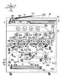
図1は本発明の給紙装置および給紙方法を備えた画像形成装置の全体説明図である。
図1において、本発明の実施例1の画像形成装置(デジタル複写機)Uは、プリンタ(画像形成装置本体)U1、イメージスキャナU2、自動原稿搬送装置U3を有している。
前記自動原稿搬送装置U3は、イメージスキャナU2上面のプラテンガラスPG上に支持されている。
前記自動原稿搬送装置U3は、複写しようとする複数の原稿Giが重ねて載置される原稿給紙トレイTG1を有している。前記原稿給紙トレイTG1に載置された複数の各原稿Giは順次プラテンガラスPG上の複写位置(プラテンロールGR1の圧接位置)を通過して原稿排出ロールGR2から原稿排紙トレイTG2に排出されるように構成されている。
FIG. 1 is an overall explanatory view of an image forming apparatus provided with a paper feeding device and a paper feeding method of the present invention.
In FIG. 1, an image forming apparatus (digital copying machine) U according to the first embodiment of the present invention includes a printer (image forming apparatus main body) U1, an image scanner U2, and an automatic document feeder U3.
The automatic document feeder U3 is supported on a platen glass PG on the upper surface of the image scanner U2.
The automatic document feeder U3 has a document feed tray TG1 on which a plurality of documents Gi to be copied are stacked. Each of the plurality of documents Gi placed on the document feed tray TG1 sequentially passes through the copy position on the platen glass PG (the press contact position of the platen roll GR1) and is discharged from the document discharge roll GR2 to the document discharge tray TG2. It is comprised so that.
前記自動原稿搬送装置U3は、その後端部(−X端部)に設けた左右方向に延びるヒンジ軸(図示せず)により前記プラテンガラスPG上面に対して回動可能であり、原稿Giを作業者が手でプラテンガラスPG上に置く場合に上方に回動される。
前記イメージスキャナU2は、ユーザがコピースタート等の作動指令信号を入力操作するUI(ユーザインタフェース)を有している。
前記透明なプラテンガラスPGの下方には原稿画像を読み取るための露光光学系Aが配置されている。
前記自動原稿搬送装置U3でプラテンガラスPG上面に搬送される原稿または手動でプラテンガラスPG上に置かれた原稿(図示せず)からの反射光は、前記露光光学系Aを介して、CCD(固体撮像素子)で電気信号に変換される。
The automatic document feeder U3 is rotatable with respect to the upper surface of the platen glass PG by a hinge shaft (not shown) extending in the left-right direction provided at the rear end portion (-X end portion). When a person puts it on the platen glass PG by hand, it is rotated upward.
The image scanner U2 has a UI (user interface) through which a user inputs an operation command signal such as a copy start.
An exposure optical system A for reading a document image is disposed below the transparent platen glass PG.
Reflected light from a document transported to the upper surface of the platen glass PG by the automatic document transport device U3 or a document (not shown) manually placed on the platen glass PG is passed through the exposure optical system A to a CCD ( It is converted into an electrical signal by a solid-state imaging device).
IPS(イメージプロセッシングシステム)は、前記CCDから入力されるR,G,B(レッド、グリーン、ブルー)の電気信号をY,M,C,K(イエロー、マゼンタ、シアン、黒)の画像データ(デジタルデータ)に変換して一時的に記憶し、前記画像データを所定のタイミングで潜像形成用の画像データとしてレーザ駆動回路DLに出力する。
レーザ駆動回路DLは、入力された画像データに応じてレーザ駆動信号をROS(潜像形成装置)のレーザダイオード(図示せず)に出力する。なお、前記UI(ユーザインタフェース)、IPSおよびレーザ駆動回路DLと、後述の現像ロールR0y〜R0k、転写ロールT1y〜T1k,2次転写ロール(シート転写部材)T2b等にバイアス電圧を印加する電源回路E等の動作はコントローラCにより制御される。
前記IPSが出力するYMCKの4色の画像データ(レーザ駆動データ)が入力されたレーザ駆動回路DLは入力された前記各色の画像データに応じた各色のレーザ駆動信号を所定のタイミングで、各色のROS(潜像形成装置)に出力する。
The IPS (image processing system) converts R, G, B (red, green, blue) electrical signals input from the CCD into Y, M, C, K (yellow, magenta, cyan, black) image data ( (Digital data) and temporarily stored, and the image data is output to the laser drive circuit DL as image data for forming a latent image at a predetermined timing.
The laser drive circuit DL outputs a laser drive signal to a laser diode (not shown) of a ROS (latent image forming apparatus) in accordance with the input image data. A power supply circuit for applying a bias voltage to the UI (user interface), the IPS and the laser driving circuit DL, and developing rolls R0y to R0k, transfer rolls T1y to T1k, a secondary transfer roll (sheet transfer member) T2b, which will be described later. Operations such as E are controlled by the controller C.
The laser drive circuit DL to which the four-color image data (laser drive data) of YMCK output from the IPS is input receives a laser drive signal of each color corresponding to the input image data of each color at a predetermined timing. Output to ROS (latent image forming apparatus).
各像担持体Py,Pm,Pc,Pkはそれぞれの帯電ロール(帯電部材)CRy〜CRkにより一様に帯電された後、前記各色のROS(潜像形成装置)の出力するレーザビームLによりその表面に静電潜像が形成される。前記像担持体Py,Pm,Pc,Pk表面の静電潜像はそれぞれ、各現像装置Gy,Gm,Gc,Gkと対向する現像領域において各色YMCKのトナー像に現像される。なお、前記各現像装置Gy,Gm,Gc,Gkは、各色のトナーを収容した現像容器と、前記現像容器に回転可能に支持され且つ前記像担持体Py,Pm,Pc,Pk表面の静電潜像にトナーを搬送してトナー像に現像する現像ロールR0y〜R0kを有している。なお、前記各色のトナーを収容した現像容器にはトナーカートリッジTy〜Tkから各色のトナーが補給されるように構成されている。
前記現像された各色Y,M,C,Kのトナー像は、前記各像担持体Py,Pm,Pc,Pkとエンドレスの中間転写ベルトBとが接触する1次転写領域Q3に搬送される。前記各1次転写領域Q3において中間転写ベルトBの裏面側に配置された1次転写ロールT1y〜T1kには、コントローラCにより制御される電源回路Eから所定のタイミングで現像剤の帯電極性と逆極性の1次転写電圧が印加される。前記各像担持体Py〜Pk上のトナー像は前記1次転写ロールT1y〜T1kに対向する1次転写領域Q3において中間転写ベルトBに重ねて1次転写される。1次転写後の像担持体Py,Pm,Pc,Pk表面の残留トナーは、像担持体クリーナCLpで除去される。
The image carriers Py, Pm, Pc, and Pk are uniformly charged by the respective charging rolls (charging members) CRy to CRk, and then the laser beams L output from the ROSs (latent image forming apparatuses) of the respective colors. An electrostatic latent image is formed on the surface. The electrostatic latent images on the surfaces of the image carriers Py, Pm, Pc, and Pk are developed into toner images of the respective colors YMCK in the developing areas that face the developing devices Gy, Gm, Gc, and Gk, respectively. Each of the developing devices Gy, Gm, Gc, and Gk includes a developing container that accommodates toner of each color, and is electrostatically supported on the surface of the image carriers Py, Pm, Pc, and Pk. It has developing rolls R0y to R0k for conveying toner to the latent image and developing the toner image. The developer containers containing the respective color toners are configured to be supplied with the respective color toners from the toner cartridges Ty to Tk.
The developed toner images of the colors Y, M, C, and K are conveyed to a primary transfer region Q3 where the image carriers Py, Pm, Pc, and Pk and the endless intermediate transfer belt B are in contact with each other. The primary transfer rolls T1y to T1k disposed on the back side of the intermediate transfer belt B in each primary transfer region Q3 are opposite to the developer charging polarity at a predetermined timing from the power supply circuit E controlled by the controller C. A polar primary transfer voltage is applied. The toner images on the image carriers Py to Pk are primarily transferred to the intermediate transfer belt B in the primary transfer region Q3 facing the primary transfer rolls T1y to T1k. Residual toner on the surface of the image carrier Py, Pm, Pc, Pk after the primary transfer is removed by the image carrier cleaner CLp.
前記各像担持体Py〜Pk、各色のROS(潜像形成装置)、各色の現像装置Gy〜Gkによって、各色のトナー像形成装置UY(Py+ROS+Gy),UM(Pm+ROS+Gm),UC(Pc+ROS+Gc),UK(Pk+ROS+Gk)が構成される。
前記各色の像担持体Py,Pm,Pc,Pkの下方には左右一対のスライドレールSR,SRによりスライドフレームF1が前後(紙面に垂直な方向)にスライド移動可能に支持されている。スライドフレームF1にはベルトモジュールBMのベルトフレームF2が上昇した動作位置と下方に移動したメンテナンス位置との間で昇降可能に支持されている。前記スライドフレームF1を前後移動させる構成およびベルトモジュールBMを昇降させる構成は、従来公知(例えば、特開平8−171248号公報参照)であり、従来公知の種々の構成を採用することが可能である。
Each of the image carriers Py to Pk, each color ROS (latent image forming device), each color developing device Gy to Gk, each color toner image forming device UY (Py + ROS + Gy), UM (Pm + ROS + Gm), UC (Pc + ROS + Gc), UK (Pk + ROS + Gk) is configured.
Below the image carriers Py, Pm, Pc, Pk of the respective colors, a slide frame F1 is supported by a pair of left and right slide rails SR, SR so as to be slidable forward and backward (in a direction perpendicular to the paper surface). The slide frame F1 is supported so that the belt frame F2 of the belt module BM can be moved up and down between the raised operating position and the maintenance position moved downward. The configuration for moving the slide frame F1 back and forth and the configuration for moving the belt module BM up and down are conventionally known (see, for example, JP-A-8-171248), and various conventionally known configurations can be employed. .
前記ベルトモジュールBMは、前記中間転写ベルトBと、ベルト駆動ロールRd、テンションロールRt、ウォーキングロールRw、複数のアイドラロール(フリーロール)RfおよびバックアップロールT2aを含むベルト支持ロール(Rd,Rt,Rw,Rf,T2a)と、前記4個の1次転写ロールT1y〜T1kとを有している。そして、前記中間転写ベルトBは前記ベルト支持ロール(Rd,Rt,Rw,Rf,T2a)により矢印Ya方向に回転移動可能に支持されている。
前記バックアップロールT2aに接する中間転写ベルトBの表面に対向して2次転写ロール(シート転写部材)T2bが配置されており、中間転写ベルトBおよび2次転写ロールT2bが対向する領域には2次転写領域(シート転写領域)Q4が形成される。前記2次転写ロールT2bにはコントローラCにより制御される電源回路Eから所定のタイミングで現像剤の帯電極性と逆極性の2次転写電圧が印加される。前記2次転写ロールT2bに対向して配置された前記バックアップロールT2aはアース(接地)されており、前記2次転写ロールT2bに2次転写電圧が印加されたときには、前記2次転写ロールT2bおよびバックアップロールT2a間には2次転写電界が形成される。前記バックアップロールT2aおよび2次転写ロールT2bにより2次転写器T2が構成される。
The belt module BM includes a belt support roll (Rd, Rt, Rw) including the intermediate transfer belt B, a belt drive roll Rd, a tension roll Rt, a walking roll Rw, a plurality of idler rolls (free rolls) Rf, and a backup roll T2a. , Rf, T2a) and the four primary transfer rolls T1y to T1k. The intermediate transfer belt B is supported by the belt support rolls (Rd, Rt, Rw, Rf, T2a) so as to be rotatable in the arrow Ya direction.
A secondary transfer roll (sheet transfer member) T2b is disposed facing the surface of the intermediate transfer belt B in contact with the backup roll T2a. A transfer region (sheet transfer region) Q4 is formed. A secondary transfer voltage having a polarity opposite to the charging polarity of the developer is applied to the secondary transfer roll T2b from a power supply circuit E controlled by the controller C at a predetermined timing. The backup roll T2a disposed opposite to the secondary transfer roll T2b is grounded, and when a secondary transfer voltage is applied to the secondary transfer roll T2b, the secondary transfer roll T2b and A secondary transfer electric field is formed between the backup rolls T2a. The backup roll T2a and the secondary transfer roll T2b constitute a secondary transfer device T2.
前記4個の1次転写ロールT1y〜T1k、中間転写ベルトBおよび2次転写器T2等により、トナー像形成装置(UY,UM,UC,UK)の像担持体Py〜Pk表面に形成されたトナー像を用紙Sに転写する転写装置(T1y〜T1k,B,T2)が構成されている。
プリンタ(画像形成装置本体)U1の下部には、用紙S(S1,S2…Sn)を収容した給紙トレイTR1および給紙用搬送路SH1が設けられている。前記給紙トレイTR1に収容された用紙Sは、所定のタイミングで前端側用紙ピックアップユニット(前端側部材)Rp1、後端側用紙ピックアップユニット(後端側部材)Rp2およびさばきロールRsにより1枚づつ分離されて取り出され、搬送ロールRaによりレジロールRrに搬送される。前記レジロールRrに搬送された用紙Sは、前記1次転写された多重トナー像または単色トナー像が2次転写領域Q4に移動するのにタイミングを合わせて、2次転写領域Q4に搬送される。
前記2次転写領域Q4を用紙Sが通過する際、2次転写ロールT2bに前記2次転写電圧が印加されるので、前記中間転写ベルトBに重ねて1次転写されたカラートナー像は、前記2次転写領域Q4において一括して用紙Sに2次転写される。
2次転写後の中間転写ベルトBはベルトクリーナCLbにより残留トナーが除去される。トナー像が2次転写された前記用紙Sは、転写後シートガイドSG、シート搬送ベルトHBにより定着ニップQ5に搬送される。
The four primary transfer rolls T1y to T1k, the intermediate transfer belt B, the secondary transfer unit T2, and the like are formed on the surface of the image carrier Py to Pk of the toner image forming apparatus (UY, UM, UC, UK). A transfer device (T1y to T1k, B, T2) for transferring the toner image onto the paper S is configured.
A paper feed tray TR1 containing paper S (S1, S2,... Sn) and a paper feed transport path SH1 are provided below the printer (image forming apparatus main body) U1. The sheets S stored in the sheet feeding tray TR1 are fed one by one by a front end side paper pickup unit (front end side member) Rp1, a rear end side paper pickup unit (rear end side member) Rp2 and a separating roll Rs at a predetermined timing. The separated roll is taken out and conveyed to the registration roll Rr by the conveyance roll Ra. The sheet S transported to the registration roll Rr is transported to the secondary transfer area Q4 in time with the primary transfer of the multiple toner image or single color toner image moving to the secondary transfer area Q4.
When the sheet S passes through the secondary transfer region Q4, the secondary transfer voltage is applied to the secondary transfer roll T2b. Therefore, the color toner image primarily transferred over the intermediate transfer belt B is Secondary transfer is performed on the sheet S at once in the secondary transfer region Q4.
The residual toner is removed from the intermediate transfer belt B after the secondary transfer by the belt cleaner CLb. The sheet S on which the toner image is secondarily transferred is conveyed to the fixing nip Q5 by the post-transfer sheet guide SG and the sheet conveying belt HB.
前記シート搬送ベルトHBにより前記搬送された前記用紙Sは、前記定着ニップQ5を通過する際、加熱ロール(加熱回転部材)Fhおよび加圧ロール(加圧回転部材)Fpにより構成される一対の定着ロール(Fh+Fp)を有する定着装置Fにより加熱定着される。
トナー像が定着した用紙Sは、シート排出路SH2または連続記録用搬送路SH3に搬送される。前記シート排出路SH2に搬送された用紙Sは記録用紙排紙トレイTRhに排出され、前記連続記録用搬送路SH3に搬送された用紙は反転されてシート循環路SH4を通過して前記レジロールRrに再送される。
前記さばきロールRsの用紙搬送方向下流側には、前記用紙Sの先端を検出する用紙検出センサSN1が配置されている。
前記さばきロールRs、前端側用紙ピックアップユニットRp1および後端側用紙ピックアップユニットRp2により、実施例1の給紙装置(Rp1,Rp2,Rs)が構成されている。
前記給紙装置(Rp1,Rp2,Rs)、レジロールRr、転写後シートガイドSG、シート搬送ベルトHB、給紙用搬送路SH1、シート排出路SH2、連続記録用搬送路SH3およびシート循環路SH4によりシート搬送装置SHが構成されている。
When the sheet S conveyed by the sheet conveying belt HB passes through the fixing nip Q5, a pair of fixing units configured by a heating roll (heating rotation member) Fh and a pressure roll (pressure rotation member) Fp. Heat fixing is performed by a fixing device F having a roll (Fh + Fp).
The sheet S on which the toner image is fixed is conveyed to the sheet discharge path SH2 or the continuous recording conveyance path SH3. The sheet S conveyed to the sheet discharge path SH2 is discharged to the recording sheet discharge tray TRh, and the sheet conveyed to the continuous recording conveyance path SH3 is reversed and passes through the sheet circulation path SH4 to the registration roll Rr. Resent.
A sheet detection sensor SN1 that detects the leading edge of the sheet S is disposed on the downstream side of the separating roll Rs in the sheet conveyance direction.
The separating roll Rs, the front end side paper pickup unit Rp1 and the rear end side paper pickup unit Rp2 constitute the paper feeding device (Rp1, Rp2, Rs) of the first embodiment.
By the sheet feeding device (Rp1, Rp2, Rs), the registration roll Rr, the post-transfer sheet guide SG, the sheet conveying belt HB, the sheet feeding conveying path SH1, the sheet discharging path SH2, the continuous recording conveying path SH3, and the sheet circulation path SH4. A sheet conveying device SH is configured.
(給紙装置)
図2は本発明の実施例1の給紙装置の説明図であり、実施例1の画像形成装置の制御部分が備えている各機能をブロック図(機能ブロック図)で示した図である。
図1、図2において、前記給紙装置(Rp1,Rp2,Rs)の前端側用紙ピックアップユニットRp1は、中心に回動軸1aが設けられた前端側回動レバー1と、前記前端側回動レバー1の左端部(−Y方向端部)に回転可能に支持された前端側用紙取出ロール2と、前記前端側回動レバー1の右端部(Y方向端部)に固定された前端側用紙押圧部材3と、を有している。前記前端側回動レバー1の回動軸1aには、前記前端側用紙取出ロール2に回転力を伝達するギヤG1が装着されている。
前記給紙装置(Rp1,Rp2,Rs)の後端側用紙ピックアップユニットRp2は、中心に回動軸6aが設けられた後端側回動レバー6と、前記後端側回動レバー6の左端部に回転可能に支持された後端側用紙取出ロール7と、前記後端側回動レバー6の右端部に固定された後端側用紙押圧部材8と、を有している。前記後端側回動レバー6の回動軸6aには、前記後端側用紙取出ロール7に回転力を伝達するギヤG2が装着されている。
(Paper feeder)
FIG. 2 is an explanatory diagram of the sheet feeding device according to the first exemplary embodiment of the present invention, and is a block diagram (functional block diagram) illustrating each function provided in the control unit of the image forming apparatus according to the first exemplary embodiment.
1 and 2, the front end side paper pickup unit Rp1 of the paper feeding device (Rp1, Rp2, Rs) includes a front end
The rear end side paper pickup unit Rp2 of the paper feeding device (Rp1, Rp2, Rs) includes a rear end side
(実施例1の制御部の説明)
図2において、前記コントローラCは、外部との信号の入出力および入出力信号レベルの調節等を行うI/O(入出力インターフェース)、必要な処理を行うためのプログラムおよびデータ等が記憶されたROM(リードオンリーメモリ)やハードディスク、必要なデータを一時的に記憶するためのRAM(ランダムアクセスメモリ)、前記ROM等に記憶されたプログラムに応じた処理を行うCPU(中央演算処理装置)、ならびにクロック発振器等を有するマイクロコンピュータにより構成されており、前記ROM等に記憶されたプログラムを実行することにより種々の機能を実現することができる。
(Description of the control part of Example 1)
In FIG. 2, the controller C stores an I / O (input / output interface) that performs input / output of signals to / from the outside and adjustment of input / output signal levels, programs and data for performing necessary processing, and the like. ROM (read-only memory), hard disk, RAM (random access memory) for temporarily storing necessary data, CPU (central processing unit) that performs processing according to programs stored in the ROM, etc., and It is constituted by a microcomputer having a clock oscillator or the like, and various functions can be realized by executing a program stored in the ROM or the like.
(前記コントローラCに接続された信号入力要素)
前記コントローラCは、UI(ユーザインタフェース)、用紙検出センサSN1等の信号入力要素からの信号が入力されている。
前記UIは、表示部UI1、コピースタートキーUI2、テンキーUI3、…等の入力キーを備えており、それらが入力されたことを検出して、その検出信号をコントローラCに入力する。
前記用紙検出センサSN1は、前記給紙トレイTR1から給紙されて前記給紙用搬送路SH1を搬送される用紙Sの先端を検出する
(Signal input element connected to the controller C)
The controller C receives signals from signal input elements such as a UI (user interface) and a sheet detection sensor SN1.
The UI includes input keys such as a display unit UI1, a copy start key UI2, a numeric keypad UI3,..., Detects that they are input, and inputs a detection signal to the controller C.
The paper detection sensor SN1 detects the leading edge of the paper S that is fed from the paper feed tray TR1 and transported through the paper feed transport path SH1.
(前記コントローラCに接続された制御要素)
前記コントローラCは、メインモータ駆動回路D1、前端側用紙ピックアップユニット駆動回路D2、後端側用紙ピックアップユニット駆動回路D3、用紙取出ロール駆動回路D4、電源回路E、その他の制御要素に接続されており、それらの作動制御信号を出力している。
前記電源回路Eは現像用電源回路E1y〜E1k、帯電用電源回路E2y〜E2k、転写用電源回路E3y〜E3kおよび2次転写用電源回路E3t、定着用電源回路E4等を有する。
前記現像用電源回路E1y〜E1kは、前記現像装置Gy〜Gkの現像ロールR0y〜R0kに現像バイアスを印加する。
前記帯電用電源回路E2y〜E2kは、前記Y,M,C,Kの各色のトナー像形成用の帯電ロールCRy〜CRkに帯電バイアスを印加する。
前記転写用電源回路E3y〜E3kは、前記一次転写ロールT1y〜T1kに転写バイアスを印加する。前記2次転写用電源回路E3tは、2次転写ロールT2bに2次転写バイアスを印加する。
前記定着用電源回路E4は、定着装置Fの加熱ロールFhのヒータにヒータ加熱用の電流を供給する。
(Control element connected to the controller C)
The controller C is connected to a main motor drive circuit D1, a front end side paper pickup unit drive circuit D2, a rear end side paper pickup unit drive circuit D3, a paper take-out roll drive circuit D4, a power supply circuit E, and other control elements. These operation control signals are output.
The power supply circuit E includes development power supply circuits E1y to E1k, charging power supply circuits E2y to E2k, transfer power supply circuits E3y to E3k, a secondary transfer power supply circuit E3t, and a fixing power supply circuit E4.
The developing power supply circuits E1y to E1k apply a developing bias to the developing rolls R0y to R0k of the developing devices Gy to Gk.
The charging power supply circuits E2y to E2k apply a charging bias to the charging rolls CRy to CRk for forming toner images of the respective colors Y, M, C, and K.
The transfer power supply circuits E3y to E3k apply a transfer bias to the primary transfer rolls T1y to T1k. The secondary transfer power supply circuit E3t applies a secondary transfer bias to the secondary transfer roll T2b.
The fixing power supply circuit E4 supplies a heater heating current to the heater of the heating roll Fh of the fixing device F.
前記メインモータ駆動回路D1は、メインモータM1を介して像担持体PR、現像装置Gy〜Gkの現像ロールR0y〜R0k、定着装置F、搬送ロールRa等を回転駆動する。
前記前端側用紙ピックアップユニット駆動回路D2は、前端側用紙ピックアップユニット駆動モータM2の駆動を制御して、前端側回動レバー1の回動軸1aを回転制御することにより、前記前端側用紙ピックアップユニットRp1を回転制御する。
前記後端側用紙ピックアップユニット駆動回路D3は、後端側用紙ピックアップユニット駆動モータM3の駆動を制御して、後端側回動レバー6の回動軸6aを回転制御することにより、前記後端側用紙ピックアップユニットRp2を回転制御する。
前記用紙取出ロール駆動回路D4は、用紙取出ロール駆動モータM4を制御して、前記ギヤG1,G2を介して前記前端側用紙取出ロール2および後端側用紙取出ロール7を回転制御する。
The main motor driving circuit D1 rotationally drives the image carrier PR, the developing rolls R0y to R0k of the developing devices Gy to Gk, the fixing device F, the conveying roll Ra, and the like via the main motor M1.
The front end side paper pickup unit drive circuit D2 controls the driving of the front end side paper pickup unit drive motor M2 and controls the rotation of the
The rear end side paper pickup unit drive circuit D3 controls the driving of the rear end side paper pickup unit drive motor M3, and controls the rotation of the
The paper take-out roll drive circuit D4 controls the paper take-out roll drive motor M4 and controls the rotation of the front end side paper take-
(前記コントローラCの機能)
前記コントローラCは、前記各信号出力要素からの出力信号に応じた処理を実行して、前記各制御要素に制御信号を出力する機能(制御手段)を有している。前記コントローラCの機能(制御手段)を次に説明する。
C1:ジョブ制御手段
ジョブ制御手段C1は、コピースタートキーUI2の入力に応じて、前記ROS、像担持体Py〜Pk、1次転写ロールT1y〜T1k、定着装置F等の動作を制御して、画像記録動作であるジョブ(印刷動作、コピー動作)を実行する。
C2:メインモータ回転制御手段
メインモータ回転制御手段C2は、前記メインモータ駆動回路D1を制御して、像担持体Py〜Pkや現像装置Gy〜Gk、定着装置F等の駆動を制御する。
(Function of the controller C)
The controller C has a function (control means) for executing a process according to an output signal from each signal output element and outputting a control signal to each control element. The function (control means) of the controller C will be described next.
C1: Job control means The job control means C1 controls the operations of the ROS, the image carriers Py to Pk, the primary transfer rolls T1y to T1k, the fixing device F, etc. according to the input of the copy start key UI2. A job (printing operation, copying operation) that is an image recording operation is executed.
C2: Main motor rotation control means The main motor rotation control means C2 controls the main motor drive circuit D1 to control the driving of the image carriers Py to Pk, the developing devices Gy to Gk, the fixing device F, and the like.
C3:電源回路制御手段
電源回路制御手段C3は、現像用電源制御手段C3A、帯電用電源制御手段C3B、転写用電源制御手段C3C、定着用電源制御手段C3Dを有し、電源回路Eを制御して画像形成装置Uの各部材への電源供給の制御を行う。
C3A:現像用電源制御手段
現像用電源制御手段C3Aは、現像用電源回路E1y〜E1kを制御して現像バイアスを制御する。
C3B:帯電用電源制御手段
帯電用電源制御手段C3Bは、帯電用電源回路E2y〜E2kを制御して帯電バイアスを制御する。
C3C:転写用電源制御手段
転写用電源制御手段C3Cは、転写用電源回路E3y〜E3kを制御して転写バイアスを制御する。また、2次転写用電源回路E3tを制御して2次転写バイアスを制御する。
C3D:定着用電源制御手段
定着用電源制御手段C3Dは、定着用電源回路E4を制御して定着装置Fの定着温度を制御する。
C3: Power supply circuit control means The power supply circuit control means C3 includes a development power supply control means C3A, a charging power supply control means C3B, a transfer power supply control means C3C, and a fixing power supply control means C3D, and controls the power supply circuit E. The power supply to each member of the image forming apparatus U is controlled.
C3A: Development power supply control means The development power supply control means C3A controls the development power supply circuits E1y to E1k to control the development bias.
C3B: Charging power supply control means The charging power supply control means C3B controls the charging power supply circuits E2y to E2k to control the charging bias.
C3C: Transfer Power Supply Control Unit The transfer power supply control unit C3C controls the transfer power supply circuits E3y to E3k to control the transfer bias. The secondary transfer bias is controlled by controlling the secondary transfer power supply circuit E3t.
C3D: Fixing power supply control means The fixing power supply control means C3D controls the fixing power supply circuit E4 to control the fixing temperature of the fixing device F.
C4:用紙ピックアップ制御手段
用紙ピックアップ制御手段C4は、前端側用紙ピックアップユニット回動制御手段C4Aと、後端側用紙ピックアップユニット回動制御手段C4Bと、ループ形成手段C4Cと、用紙取出ロール回転制御手段C4Dと、を有している。
C4A:前端側用紙ピックアップユニット回動制御手段
前端側用紙ピックアップユニット回動制御手段C4Aは、前記前端側用紙ピックアップユニットRp1を回転制御して、前記前端側回動レバー1が水平な状態の基準位置(解放位置)、前記前端側回動レバー1を反時計方向に回動させた状態の用紙取出位置、前記前端側回動レバー1を時計方向に回動させた状態の押圧位置に、前記前端側用紙ピックアップユニットRp1を移動させる。
C4B:後端側用紙ピックアップユニット回動制御手段
後端側用紙ピックアップユニット回動制御手段C4Bは、前記後端側用紙ピックアップユニットRp2を回転制御して、前記後端側回動レバー6が水平な状態の基準位置(解放位置)、前記後端側回動レバー6を反時計方向に回動させた状態のループ形成位置(用紙取出位置)、前記後端側回動レバー6を時計方向に回動させた状態の押圧位置に、前記後端側用紙ピックアップユニットRp2を移動させる。
C4: Paper Pickup Control Unit The paper pickup control unit C4 includes a front end side paper pickup unit rotation control unit C4A, a rear end side paper pickup unit rotation control unit C4B, a loop forming unit C4C, and a paper take-out roll rotation control unit. C4D.
C4A: Front end side paper pickup unit rotation control means The front end side paper pickup unit rotation control means C4A controls the rotation of the front end side paper pickup unit Rp1 so that the front end
C4B: Rear end side paper pickup unit rotation control means The rear end side paper pickup unit rotation control means C4B controls rotation of the rear end side paper pickup unit Rp2, so that the rear end
C4C:ループ形成手段
ループ形成手段C4Cは、ループ形成時間計測タイマTM1を有しており、前記前端側用紙ピックアップユニットRp1を押圧位置に回動させて、且つ前記後端側用紙ピックアップユニットRp2をループ形成位置に回動させた状態で、前記ループ形成時間計測タイマTM1がループ形成のための所要時間TM1aを計測することより、前記給紙トレイTR1に積載された最上位の用紙S1にループを形成する。
C4D:用紙取出ロール回転制御手段
用紙取出ロール回転制御手段C4Dは、給紙終了時間計測タイマTM2を有しており、前記前端側用紙取出ロール2および後端側用紙取出ロール7を回転制御する。なお、前記用紙取出ロール回転制御手段C4Dは、給紙トレイTR1から給紙された用紙Sの先端を用紙センサSN1が検出してから、前記給紙終了時間計測タイマTM2が給紙終了時間TM2aを計測して、前記前端側用紙取出ロール2および後端側用紙取出ロール7の回転を停止する。
C4C: Loop formation means The loop formation means C4C has a loop formation time measurement timer TM1, rotates the front end side paper pickup unit Rp1 to the pressing position, and loops the rear end side paper pickup unit Rp2. The loop formation time measurement timer TM1 measures the required time TM1a for loop formation while being rotated to the formation position, thereby forming a loop on the uppermost sheet S1 stacked on the paper feed tray TR1. To do.
C4D: Paper take-out roll rotation control means The paper take-out roll rotation control means C4D has a paper feed end time measuring timer TM2, and controls the rotation of the front end side paper take-
(実施例1の給紙制御処理のフローチャートの説明)
図3は実施例1の画像形成装置の給紙制御処理のフローチャートである。
図4は実施例1の給紙方法の各工程を示した説明図であり、図4Aは前端側用紙取出ロールおよび後端側用紙取出ロールが回転した状態を示す図、図4Bは前端側用紙ピックアップユニットを押圧位置に回動させ且つ後端側用紙ピックアップユニットをループ形成位置に回動させた用紙前端部押圧工程を示す図、図4Cは給紙トレイに積載された最上位の用紙にループを形成するループ形成工程を示す図、図4Dは後端側用紙ピックアップユニットを押圧位置に回動させた用紙後端部押圧工程を示す図、図4Eは前端側用紙ピックアップユニットが基準位置に移動してループが解放されたループ解消工程を示す図、図4Fは前端側用紙ピックアップユニットを用紙取出位置に回動させた状態を示す図である。
図3のフローチャートの各ST(ステップ)の処理は、前記コントローラCのROMやハードディスク等に記憶されたプログラムに従って行われる。また、この処理は画像形成装置Uの他の各種処理と並行してマルチタスクで実行される。
(Description of Flowchart of Paper Feed Control Processing in First Embodiment)
FIG. 3 is a flowchart of the paper feed control process of the image forming apparatus according to the first embodiment.
4A and 4B are explanatory views showing the steps of the paper feeding method according to the first embodiment. FIG. 4A is a diagram showing a state in which the front end side paper take-out roll and the rear end side paper take-out roll are rotated. FIG. FIG. 4C is a diagram illustrating a sheet front end pressing process in which the pickup unit is rotated to the pressing position and the trailing edge side sheet pickup unit is rotated to the loop forming position. FIG. 4C is a diagram illustrating a loop on the uppermost sheet stacked on the sheet feeding tray. 4D is a diagram showing a sheet rear end pressing step in which the rear end side paper pickup unit is rotated to the pressing position, and FIG. 4E is a diagram showing the front end side paper pickup unit being moved to the reference position. FIG. 4F is a diagram showing a state in which the front end side paper pickup unit is rotated to the paper take-out position.
The processing of each ST (step) in the flowchart of FIG. 3 is performed according to a program stored in the ROM or hard disk of the controller C. This process is executed in a multitasking manner in parallel with other various processes of the image forming apparatus U.
図3に示すフローチャートは画像形成装置Uの電源オンにより開始される。
図3のST1において、印刷実行指示が入力されたか否かを判断する。すなわち、コピースタートキーUI2がオンになったか否かを判別する。イエス(Y)の場合はST2に移り、ノー(N)の場合はST1を繰り返し実行する。
ST2において、給紙タイミングか否かを判別する。イエス(Y)の場合はST3に移り、ノー(N)の場合はST2に戻る。
ST3において、前端側用紙取出ロール2および後端側用紙取出ロール7を回転(図4A参照)させる。
ST4において、次の処理を実行して、ST5に移る。
(1)前端側用紙ピックアップユニットRp1を押圧位置に回動させると同時に後端側用紙ピックアップユニットRp2をループ形成位置(用紙取出位置)に回動(図4B参照)させる。
(2)ループ形成時間計測タイマTM1にループ形成のための所要時間TM1aをセットする。
The flowchart shown in FIG. 3 is started when the image forming apparatus U is powered on.
In ST1 of FIG. 3, it is determined whether a print execution instruction has been input. That is, it is determined whether or not the copy start key UI2 is turned on. If yes (Y), the process proceeds to ST2. If no (N), ST1 is repeatedly executed.
In ST2, it is determined whether or not it is a paper feed timing. If yes (Y), the process proceeds to ST3, and, if no (N), the process returns to ST2.
In ST3, the front end side paper take-
In ST4, the following process is executed, and the process proceeds to ST5.
(1) The front end side paper pickup unit Rp1 is turned to the pressing position and the rear end side paper pickup unit Rp2 is turned to the loop forming position (paper takeout position) (see FIG. 4B).
(2) The required time TM1a for loop formation is set in the loop formation time measurement timer TM1.
ST5において、ループ形成時間計測タイマTM1がループ形成のための所要時間TM1aを計測したか否か(TM1がタイムアップしたか否か)を判別する。なお、前記ループ形成時間計測タイマTM1がループ形成のための所要時間TM1aを計測した場合、給紙トレイTR1に積載された最上位の用紙Sに所定のループが形成(図4C参照)される。イエス(Y)の場合はST6に移り、ノー(N)の場合はST5を繰り返し実行する。
ST6において、後端側用紙ピックアップユニットRp2を押圧位置に回動(図4D参照)させる。
ST7において、前端側用紙ピックアップユニットRp1を基準位置に回動(図4E参照)させてから続いて、前端側用紙ピックアップユニットRp1を用紙取出位置に回動(図4F参照)させる。
ST8において、用紙検出センサSN1が用紙Sの先端を検出したか否かを判別する。イエス(Y)の場合はST9に移り、ノー(N)の場合はST8を繰り返し実行する。
In ST5, it is determined whether or not the loop formation time measurement timer TM1 has measured the required time TM1a for loop formation (whether or not TM1 has timed up). When the loop formation time measurement timer TM1 measures the required time TM1a for loop formation, a predetermined loop is formed on the uppermost sheet S stacked on the paper feed tray TR1 (see FIG. 4C). If yes (Y), the process proceeds to ST6, and, if no (N), ST5 is repeatedly executed.
In ST6, the rear end side paper pickup unit Rp2 is rotated to the pressed position (see FIG. 4D).
In ST7, the front end side paper pickup unit Rp1 is turned to the reference position (see FIG. 4E), and then the front end side paper pickup unit Rp1 is turned to the paper take-out position (see FIG. 4F).
In ST8, it is determined whether or not the sheet detection sensor SN1 has detected the leading edge of the sheet S. If yes (Y), the process proceeds to ST9, and, if no (N), ST8 is repeatedly executed.
ST9において、給紙終了時間計測タイマTM2に給紙終了時間TM2aをセットする。
ST10において、給紙終了間計測タイマTM2が給紙終了時間TM2aを計測したか否か(TM2がタイムアップしたか否か)を判別する。イエス(Y)の場合はST11に移り、ノー(N)の場合はST10を繰り返し実行する。
ST11において、次の処理を実行して、ST12に移る。
(1)前端側用紙ピックアップユニットRp1を基準位置に回動(図2参照)させる。
(2)後端側用紙ピックアップユニットRp2を基準位置に回動(図2参照)させる。
(3)前端側用紙取出ロール2および後端側用紙取出ロール7を停止(図2参照)する。
ST12において、ジョブ終了か否かを判別する。イエス(Y)の場合は前記ST1に戻り、ノー(N)の場合は前記ST2に戻る。
In ST9, the paper feed end time TM2a is set in the paper feed end time measuring timer TM2.
In ST10, it is determined whether or not the paper feed end measurement timer TM2 has measured the paper feed end time TM2a (whether TM2 has timed up). If yes (Y), the process moves to ST11, and, if no (N), ST10 is repeatedly executed.
In ST11, the following process is executed, and the process proceeds to ST12.
(1) The front end side paper pickup unit Rp1 is rotated to the reference position (see FIG. 2).
(2) The rear end side paper pickup unit Rp2 is rotated to the reference position (see FIG. 2).
(3) Stop the front end side paper take-
In ST12, it is determined whether or not the job is finished. If yes (Y), the process returns to ST1, and if no (N), the process returns to ST2.
(実施例1の作用)
前記構成を備えた実施例1の画像形成装置Uでは、印刷実行指示が入力(コピースタートキーUI2が入力)されて給紙タイミングになると、前端側用紙取出ロール2および後端側用紙取出ロール7を回転(図4A参照)させる。そして、前端側用紙ピックアップユニットRp1を押圧位置に回動させると同時に後端側用紙ピックアップユニットRp2をループ形成位置(用紙取出位置)に回動させる(図4Bに示す給紙方法の用紙前端部押圧工程および前端側部材移動工程)。前記前端側用紙ピックアップユニットRp1の前端側用紙押圧部材3は、給紙トレイTR1に積載された最上位の用紙(すなわち、用紙束S1,S2…Snの最上位の用紙)S1の前端部を押圧する。
この状態から、ループ形成時間計測タイマTM1がループ形成のための所要時間TM1aを計測することにより、前記後端側用紙取出ロール7の回転に伴って前記最上位の用紙Sにループが形成される(図4Cに示すループ形成工程)。
(Operation of Example 1)
In the image forming apparatus U according to the first embodiment having the above-described configuration, when a print execution instruction is input (the copy start key UI2 is input) and the paper feed timing is reached, the front end side paper take-
From this state, the loop formation time measurement timer TM1 measures the required time TM1a for loop formation, so that a loop is formed on the uppermost sheet S as the trailing edge side sheet take-
前記後端側用紙ピックアップユニットRp2を押圧位置に回動させる。前記後端側用紙ピックアップユニットRp2を押圧位置に回動させた状態では、前記最上位の用紙S1の後端が後端側用紙押圧部材8に当接して前記ループが保持される。また、前記後端側用紙押圧部材8は、前記給紙トレイTR1に積載された上から2番目の用紙S2の後端部を下方に押圧する(図4Dに示す用紙後端部押圧工程および後端側部材移動工程)。
前記前端側用紙ピックアップユニットRp1を基準位置に回動させて前記ループを解放する(図4Eに示すループ解消工程)。このとき、前記最上位の用紙S1の後端は後端側用紙押圧部材8に当接しているため、ループ解放時に前記用紙S1の前端部が用紙搬送方向に送り出す(用紙送り出し工程)。
前記ループ解放後に、前記前端側用紙ピックアップユニットRp1を用紙取出位置に回動させる。このとき、前記最上位の用紙S1は、前記前端側用紙取出ロール2およびさばきロールRsにより、給紙用搬送路SH1に搬送される。前記給紙用搬送路SH1を用紙Sが通過する際、前記用紙S1の先端を用紙検出センサSN1が検出(図4F参照)する。
The rear end side paper pickup unit Rp2 is rotated to the pressing position. In a state where the rear end side paper pickup unit Rp2 is rotated to the pressing position, the rear end of the uppermost sheet S1 contacts the rear end side
The front end side paper pickup unit Rp1 is rotated to the reference position to release the loop (loop elimination step shown in FIG. 4E). At this time, since the rear end of the uppermost sheet S1 is in contact with the rear end side
After the loop is released, the front end side paper pickup unit Rp1 is rotated to the paper take-out position. At this time, the uppermost sheet S1 is conveyed to the sheet feeding conveyance path SH1 by the front end side sheet take-
前記用紙検出センサSN1が用紙S1の先端を検出してから、給紙終了時間計測タイマTM2が給紙終了時間TM2aを計測した場合、前記前端側用紙ピックアップユニットRp1および後端側用紙ピックアップユニットRp2を基準位置に回動させる(前端側ロール離隔工程および後端側ロール離隔工程)。また、前端側用紙取出ロール2および後端側用紙取出ロール7の回転を停止する。
When the paper feed end time measurement timer TM2 measures the paper feed end time TM2a after the paper detection sensor SN1 detects the leading edge of the paper S1, the front end side paper pickup unit Rp1 and the rear end side paper pickup unit Rp2 are detected. Rotate to the reference position (front end side roll separation step and rear end side roll separation step). Further, the rotation of the front end side paper take-
実施例1の給紙装置(Rp1,Rp2,Rs)および給紙方法を備えた画像形成装置Uでは、前記ループ形成により、前記給紙トレイTR1に積載された最上位の用紙S1と、上から2番目の用紙S2との間に空気層が形成されるため、前記用紙間の摩擦抵抗が低減される。さらに、前記上から2番目の用紙S2の後端部は、前記後端側用紙押圧部材8により下方に押圧されている。このため、前記最上位の用紙S1を前記給紙用搬送路SH1に搬送する際に発生する用紙の重送を防止することができる。
また、前記前端側用紙ピックアップユニットRp1は、前記前端側回動レバー1を回動させることにより、前記前端側用紙取出ロール2および前端側用紙押圧部材3の一方を下降させると同時に他方を上昇させることができる。前記後端側用紙ピックアップユニットRp2は、前記後端側回動レバー6を回動させることにより、前記後端側用紙取出ロール7および後端側用紙押圧部材8の一方を下降させると同時に他方を上昇させることができる。したがって、前記給紙方法および給紙装置(Rp1,Rp2,Rs)は、従来の給紙方法および給紙装置(引用文献1〜3参照)と比較して、給紙方法の制御が容易になり、給紙装置を小型化、簡素化することができる。
In the image forming apparatus U including the paper feeding device (Rp1, Rp2, Rs) and the paper feeding method according to the first exemplary embodiment, the uppermost paper S1 stacked on the paper feeding tray TR1 and the top sheet S1 are formed from the top by the loop formation. Since an air layer is formed between the second sheet S2, the frictional resistance between the sheets is reduced. Further, the rear end portion of the
Further, the front end side paper pickup unit Rp1 lowers one of the front end side paper take-
(実施例2)
図5は実施例2の給紙装置および給紙トレイの説明図であり、図5Aは実施例2の画像形成装置の制御部分が備えている各機能をブロック図(機能ブロック図)で示した図、図5Bは実施例2の給紙トレイの斜視図である。
なお、この実施例2の説明において、前記実施例1の構成要素に対応する構成要素には同一の符号を付して、その詳細な説明を省略する。
この実施例2は、下記の点で前記実施例1と相違しているが、他の点では前記実施例1と同様に構成されている。
図5Bにおいて、実施例2の給紙トレイTR1′は、用紙Sの幅方向(前後方向、X軸方向)の位置を規制する用紙位置決め壁TR1a′,TR1a′を有している。前記用紙位置決め壁TR1a′の上端部には、前記給紙トレイTR1′の内側に突出する内方突出爪9が形成されている。前記給紙トレイTR1′に収容された用紙Sは、図5Bに示す矢印Yb方向に給紙される。
(Example 2)
FIG. 5 is an explanatory diagram of the sheet feeding device and the sheet feeding tray according to the second embodiment. FIG. 5A is a block diagram (functional block diagram) illustrating each function included in the control unit of the image forming apparatus according to the second embodiment. FIG. 5B is a perspective view of the paper feed tray according to the second embodiment.
In the description of the second embodiment, components corresponding to those of the first embodiment are denoted by the same reference numerals, and detailed description thereof is omitted.
The second embodiment is different from the first embodiment in the following points, but is configured in the same manner as the first embodiment in other points.
5B, the paper feed tray TR1 ′ according to the second embodiment includes paper positioning walls TR1a ′ and TR1a ′ that regulate the position of the paper S in the width direction (front-rear direction and X-axis direction). An inward projecting
(給紙装置)
図5Aにおいて、実施例2の前端側用紙ピックアップユニットRp1′は、左端部(−Y方向端部)に回動軸1a′が設けられた前端側回動レバー1′と、前記前端側回動レバー1′の右端部(Y方向端部)に固定された前端側用紙押圧部材3′と、を有している。
前記前端側用紙ピックアップユニットRp1′、後端側用紙ピックアップユニットRp2およびさばきロールRsにより、実施例2の給紙装置(Rp1′,Rp2,Rs)が構成されている。
(Paper feeder)
5A, the front end side paper pickup unit Rp1 ′ according to the second embodiment includes a front end
The front end side paper pickup unit Rp1 ′, the rear end side paper pickup unit Rp2 and the separating roll Rs constitute a paper feeder (Rp1 ′, Rp2, Rs) of the second embodiment.
(実施例2の制御部の説明)
図5Aにおいて、コントローラCは、外部との信号の入出力および入出力信号レベルの調節等を行うI/O(入出力インターフェース)、必要な処理を行うためのプログラムおよびデータ等が記憶されたROM(リードオンリーメモリ)やハードディスク、必要なデータを一時的に記憶するためのRAM(ランダムアクセスメモリ)、前記ROM等に記憶されたプログラムに応じた処理を行うCPU(中央演算処理装置)、ならびにクロック発振器等を有するマイクロコンピュータにより構成されており、前記ROM等に記憶されたプログラムを実行することにより種々の機能を実現することができる。
(Description of Control Unit of Example 2)
In FIG. 5A, a controller C is a ROM that stores I / O (input / output interface) for input / output of signals to / from the outside and adjustment of input / output signal levels, programs and data for performing necessary processing, (Read-only memory), hard disk, RAM (random access memory) for temporarily storing necessary data, CPU (central processing unit) for processing according to programs stored in the ROM, etc., and clock It is composed of a microcomputer having an oscillator or the like, and various functions can be realized by executing a program stored in the ROM or the like.
(前記コントローラCに接続された制御要素)
前記コントローラCは、メインモータ駆動回路D1、前端側用紙ピックアップユニット駆動回路D2′、後端側用紙ピックアップユニット駆動回路D3、用紙取出ロール駆動回路D4′、電源回路E、その他の制御要素に接続されており、それらの作動制御信号を出力している。
前記前端側用紙ピックアップユニット駆動回路D2′は、前端側用紙ピックアップユニット駆動モータM2′の駆動を制御して、前端側回動レバー1′の回動軸1a′を回転制御することにより、前記前端側用紙ピックアップユニットRp1′を回転制御する。
前記用紙取出ロール駆動回路D4′は、用紙取出ロール駆動モータM4′を制御して、前記ギヤG2を介して後端側用紙取出ロール7を回転制御する。
(Control element connected to the controller C)
The controller C is connected to a main motor drive circuit D1, a front end side paper pickup unit drive circuit D2 ', a rear end side paper pickup unit drive circuit D3, a paper take-out roll drive circuit D4', a power supply circuit E, and other control elements. And output their operation control signals.
The front end side paper pickup unit drive circuit D2 ′ controls the drive of the front end side paper pickup unit drive motor M2 ′ and controls the rotation of the
The paper take-out roll drive circuit D4 'controls the paper take-out roll drive motor M4' to control the rotation of the rear end side paper take-
(実施例2のコントローラCの機能)
実施例2のコントローラCは、前記各信号出力要素からの出力信号に応じた処理を実行して、前記各制御要素に制御信号を出力する機能(制御手段)を有している。前記コントローラCの機能(制御手段)を次に説明する。
なお、図5に示す実施例2のコントローラCの機能は、前記図3に示す実施例1のコントローラCの機能と下記の点で相違している。なお、実施例2のコントローラCの説明において、前記実施例1のコントローラCと同一の機能に対しては同一の符号を付して詳細な説明を省略する。
図5に示す実施例2のコントローラCの機能では、前記図3に示す実施例1の前端側用紙ピックアップユニット回動制御手段C4Aおよびループ形成手段C4Cの代わりに前端側用紙ピックアップユニット回動制御手段C4A′およびループ形成手段C4C′が設けられている。
(Function of the controller C of the second embodiment)
The controller C according to the second embodiment has a function (control means) for executing a process according to an output signal from each signal output element and outputting a control signal to each control element. The function (control means) of the controller C will be described next.
The function of the controller C of the second embodiment shown in FIG. 5 is different from the function of the controller C of the first embodiment shown in FIG. In the description of the controller C of the second embodiment, the same functions as those of the controller C of the first embodiment are denoted by the same reference numerals, and detailed description thereof is omitted.
In the function of the controller C of the second embodiment shown in FIG. 5, the front end side paper pickup unit rotation control means instead of the front end side paper pickup unit rotation control means C4A and loop forming means C4C of the first embodiment shown in FIG. C4A ′ and loop forming means C4C ′ are provided.
C4:用紙ピックアップ制御手段
用紙ピックアップ制御手段C4は、前端側用紙ピックアップユニット回動制御手段C4A′と、後端側用紙ピックアップユニット回動制御手段C4Bと、ループ形成手段C4C′と、用紙取出ロール回転制御手段C4Dと、を有している。
C4A′:前端側用紙ピックアップユニット回動制御手段
前端側用紙ピックアップユニット回動制御手段C4A′は、前記前端側回動レバー1′が水平な状態の基準位置(解放位置)および前記前端側回動レバー1′を時計方向に回動させた状態の押圧位置に、前記前端側用紙ピックアップユニットRp1′を回転制御する。
C4C′:ループ形成手段
ループ形成手段C4C′は、ループ形成時間計測タイマTM1を有しており、前記前端側用紙ピックアップユニットRp1′を押圧位置に回動させて且つ、前記後端側用紙ピックアップユニットRp2をループ形成位置(用紙取出位置)に回動させた状態で、前記ループ形成時間計測タイマTM1がループ形成のための所要時間TM1aを計測することより、前記給紙トレイTR1に積載された最上位の用紙S1にループを形成する。
C4: Paper Pickup Control Unit The paper pickup control unit C4 includes a front end side paper pickup unit rotation control unit C4A ′, a rear end side paper pickup unit rotation control unit C4B, a loop forming unit C4C ′, and a paper take-out roll rotation. Control means C4D.
C4A ′: Front end side paper pickup unit rotation control means The front end side paper pickup unit rotation control means C4A ′ is a reference position (release position) in which the front end
C4C ′: Loop forming means The loop forming means C4C ′ has a loop forming time measuring timer TM1, and rotates the front end side paper pickup unit Rp1 ′ to the pressing position, and the rear end side paper pickup unit. In a state where Rp2 is rotated to the loop formation position (paper take-out position), the loop formation time measurement timer TM1 measures the required time TM1a for loop formation, whereby the most loaded paper feed tray TR1 is loaded. A loop is formed on the upper sheet S1.
(実施例2の給紙制御処理のフローチャートの説明)
図6は実施例2の画像形成装置の給紙制御処理のフローチャートである。
図7は実施例2の給紙方法の各工程を示した説明図であり、図7Aは後端側用紙取出ロールが回転した状態を示す図、図7Bは前端側用紙ピックアップユニットを押圧位置に回動させ且つ後端側用紙ピックアップユニットをループ形成位置に回動させた用紙前端部押圧工程を示す図、図7Cは給紙トレイに積載された最上位の用紙にループを形成するループ形成工程を示す図、図7Dは後端側用紙ピックアップユニットを押圧位置に回動させた用紙後端部押圧工程を示す図、図7Eは前端側用紙ピックアップユニットが基準位置に移動してループが解放された用紙が搬送される用紙送り出し工程を示す図である。
なお、図6に示す給紙制御処理のフローチャートは、前記図3に示す給紙制御処理のフローチャートと下記の点で相違している。なお、図6のフローチャートの説明において、前記図3のフローチャートのステップと同一の処理に対しては同一のスッテップ(ST)番号を付して詳細な説明を省略する。
図6のフローチャートでは、前記図3のフローチャートのST3、ST4、ST7、ST11の代わりにST3′、ST4′、ST7′、ST11′が設けられている。
(Explanation of Flowchart of Paper Feed Control Processing in Embodiment 2)
FIG. 6 is a flowchart of the paper feed control process of the image forming apparatus according to the second embodiment.
FIG. 7 is an explanatory view showing each step of the paper feeding method of the second embodiment, FIG. 7A is a diagram showing a state where the rear end side paper take-out roll is rotated, and FIG. 7B is a diagram showing the front end side paper pick-up unit in the pressing position. FIG. 7C is a diagram illustrating a sheet front end pressing process in which the rear end sheet pickup unit is rotated to the loop forming position, and FIG. 7C is a loop forming process for forming a loop on the uppermost sheet loaded on the sheet feeding tray. FIG. 7D is a diagram showing a sheet trailing edge pressing process in which the trailing edge side paper pickup unit is rotated to the pressing position, and FIG. 7E is a diagram showing the leading edge sheet pickup unit moving to the reference position and releasing the loop. FIG. 10 is a diagram illustrating a sheet feeding process in which a stacked sheet is conveyed.
The flowchart of the paper feed control process shown in FIG. 6 is different from the flowchart of the paper feed control process shown in FIG. In the description of the flowchart of FIG. 6, the same step (ST) number is attached to the same process as the step of the flowchart of FIG. 3 and the detailed description is omitted.
In the flowchart of FIG. 6, ST3 ', ST4', ST7 'and ST11' are provided instead of ST3, ST4, ST7 and ST11 in the flowchart of FIG.
図6に示すフローチャートは画像形成装置Uの電源オンにより開始される。
図3のST3′において、後端側用紙取出ロール7を回転(図7A参照)させる。
ST4′において、次の処理を実行して、ST5に移る。
(1)前端側用紙ピックアップユニットRp1′を押圧位置に回動させると同時に後端側用紙ピックアップユニットRp2をループ形成位置(用紙取出位置)に回動(図7B参照)させる。
(2)ループ形成時間計測タイマTM1にループ形成のための所要時間TM1aをセットする。
ST7′において、前端側用紙ピックアップユニットRp1′を基準位置に回動(図7E参照)る。
ST11′において、次の処理を実行して、ST12に移る。
(1)後端側用紙ピックアップユニットRp2を基準位置に回動(図5参照)させる。
(2)後端側用紙取出ロール7を停止(図5参照)する。
The flowchart shown in FIG. 6 is started when the image forming apparatus U is powered on.
In ST3 ′ of FIG. 3, the trailing edge side paper take-
In ST4 ′, the following processing is executed, and the process proceeds to ST5.
(1) The front end side paper pickup unit Rp1 ′ is turned to the pressing position, and the rear end side paper pickup unit Rp2 is turned to the loop forming position (paper takeout position) (see FIG. 7B).
(2) The required time TM1a for loop formation is set in the loop formation time measurement timer TM1.
In ST7 ′, the front end side paper pickup unit Rp1 ′ is rotated to the reference position (see FIG. 7E).
In ST11 ′, the following process is executed, and the process proceeds to ST12.
(1) The rear end side paper pickup unit Rp2 is rotated to the reference position (see FIG. 5).
(2) Stop the trailing edge side sheet take-out roll 7 (see FIG. 5).
(実施例2の作用)
前記構成を備えた実施例2の画像形成装置Uでは、給紙トレイTR1′に積載された最上位の用紙S1の中央部がループを形成する際、内方突出爪9,9が前記最上位の用紙S1の幅方向両端部(前後両端部、X軸方向両端部)を弾く工程(ループ形成時用紙端部弾き工程)が生じる。前記最上位の用紙S1の幅方向両端部を弾くことにより、複数の用紙S(S1,S2…Sn)が同時にループを形成されることを防止することができる。
また、前端側用紙ピックアップユニットRp1′を基準位置に回動させた場合、用紙の剛性により前記最上位の用紙S1が用紙搬送方向に移動する(図7Eに示すループ解消工程)。そして、さばきロールRsおよび搬送ロールRaにより、給紙用搬送路SH1に搬送される(用紙送り出し工程)。
前記用紙の種類や剛性により用紙搬送方向に移動する距離が異なる場合がある。しかし、前記給紙用搬送路SH1には、前記用紙Sの先端を検出する用紙検出センサSN1が配置されているため、給紙動作の開始、終了を適切に設定することができる(用紙送り出し工程)。
(Operation of Example 2)
In the image forming apparatus U according to the second embodiment having the above-described configuration, when the central portion of the uppermost sheet S1 stacked on the sheet feeding tray TR1 ′ forms a loop, the inwardly protruding
Further, when the front end side paper pickup unit Rp1 ′ is rotated to the reference position, the uppermost paper S1 moves in the paper transport direction due to the rigidity of the paper (loop elimination step shown in FIG. 7E). Then, the paper is transported to the paper feed transport path SH1 by the separating roll Rs and the transport roll Ra (paper feeding process).
Depending on the type and rigidity of the paper, the distance moved in the paper conveyance direction may vary. However, since the sheet detection sensor SN1 for detecting the leading edge of the sheet S is disposed in the sheet feeding transport path SH1, the start and end of the sheet feeding operation can be set appropriately (sheet feeding step). ).
その他、実施例2の給紙方法および給紙装置(Rp1′,Rp2,Rs)は、前記実施例1の給紙装置(Rp1,Rp2,Rs)と同様の作用効果を奏する。すなわち、前記最上位の用紙S1を前記給紙用搬送路SH1に搬送する際に発生する用紙S(S1,S2…Sn)の重送を防止することができる。
また、前記後端側用紙ピックアップユニットRp2は、前記後端側回動レバー6を回動させることにより、前記後端側用紙取出ロール7および後端側用紙押圧部材8の一方を下降させると同時に他方を上昇させることができる。したがって、前記給紙方法および給紙装置(Rp1,Rp2,Rs)は、従来の給紙方法および給紙装置(引用文献1〜3参照)と比較して、給紙方法の制御が容易になり、給紙装置を小型化、簡素化することができる。
In addition, the paper feeding method and the paper feeding devices (Rp1 ′, Rp2, Rs) according to the second embodiment have the same effects as the paper feeding devices (Rp1, Rp2, Rs) according to the first embodiment. That is, it is possible to prevent double feeding of the sheets S (S1, S2,... Sn) generated when the uppermost sheet S1 is conveyed to the sheet feeding conveyance path SH1.
The rear end side paper pickup unit Rp2 simultaneously lowers one of the rear end side paper take-
(変更例)
以上、本発明の実施例を詳述したが、本発明は、前記各実施例に限定されるものではなく、特許請求の範囲に記載された本発明の要旨の範囲内で、種々の変更を行うことが可能である。本発明の変更実施例(H01)〜(H05)を下記に例示する。
(H01)前記各実施例において、画像形成装置Uはコピー機に限定されず、FAXやプリンタ等の画像形成装置にも適用することが可能である。
(H02)前記実施例1において、前記前端側用紙ピックアップユニットRp1および後端側用紙ピックアップユニットRp2の前端側用紙押圧部材3および後端側用紙押圧部材8を省略して、前端側用紙取出ロール2および後端側用紙取出ロール7にクラッチを設けることにより、前記前端側用紙取出ロール2および後端側用紙取出ロール7の回転・停止を制御して、給紙トレイTR1に積載された最上位の用紙Sにループを形成することも可能である。
(Example of change)
As mentioned above, although the Example of this invention was explained in full detail, this invention is not limited to each said Example, A various change is made within the range of the summary of this invention described in the claim. Is possible. Modified examples (H01) to (H05) of the present invention are exemplified below.
(H01) In each of the above embodiments, the image forming apparatus U is not limited to a copying machine, and can be applied to an image forming apparatus such as a FAX or a printer.
(H02) In the first embodiment, the front end side
(H03)前記各実施例において、前記前端側用紙ピックアップユニットRp1および後端側用紙ピックアップユニットRp2を前端側用紙ピックアップユニット駆動モータM2および後端側用紙ピックアップユニット駆動モータM3により駆動したがこれに限定されず、
前記前記前端側用紙ピックアップユニットRp1および後端側用紙ピックアップユニットRp2をソレノイド等により駆動することも可能である。
(H04)前記各実施例において、用紙取出ロール駆動回路(D4,D4′)および用紙取出ロール駆動モータ(M4,M4′)を省略して、用紙取出ロール(2,7)をメインモータM1の駆動を介して回転駆動することも可能である。
(H05)前記実施例1において、前端ピックアップユニットRp1の前端側用紙取出ロール2と前端側用紙押圧部材3とを前端側回動レバー6により接続したがこれに限定されず、前記前端側回動レバー6を省略して、前端側用紙押出ロール2および前端側用紙押圧部材3をそれぞれ独立して動作させることも可能である。また、後端ピックアップユニットRp2において、前記前端ピックアップユニットRp1と同様に、後端側用紙押出ロール7および後端側用紙押圧部材8をそれぞれ独立して動作させることも可能である。
(H03) In each of the above embodiments, the front end side paper pickup unit Rp1 and the rear end side paper pickup unit Rp2 are driven by the front end side paper pickup unit drive motor M2 and the rear end side paper pickup unit drive motor M3. not,
The front end side paper pickup unit Rp1 and the rear end side paper pickup unit Rp2 can be driven by a solenoid or the like.
(H04) In each of the above embodiments, the paper take-out roll drive circuit (D4, D4 ′) and the paper take-out roll drive motor (M4, M4 ′) are omitted, and the paper take-out roll (2, 7) is connected to the main motor M1. It is also possible to rotationally drive through the drive.
(H05) In the first embodiment, the front end side paper take-
1…前端側回動レバー、
2…前端側用紙取出ロール、
3,3′…前端側用紙押圧部材、
6…後端側回動レバー、
7…後端側用紙取出ロール、
8…後端側用紙押圧部材、
9,9…内方突出爪、
Rp1,Rp2,Rs;Rp1′,Rp2,Rs…給紙装置、
S1…用紙束の一番上の用紙、
S1,S2…Sn…用紙束、
TR1,TR1′…給紙トレイ、
TR1a′,TR1a′…用紙位置決め壁、
U…画像形成装置。
1 ... Front end side turning lever,
2. Front end side paper take-out roll,
3, 3 '... front end side paper pressing member,
6 ... rear end side turning lever,
7: Rear end side paper take-out roll,
8 ... rear end side paper pressing member,
9,9 ... inward protruding nails,
Rp1, Rp2, Rs; Rp1 ′, Rp2, Rs...
S1 ... the top sheet in the stack,
S1, S2 ... Sn ... sheet bundle,
TR1, TR1 '... paper feed tray,
TR1a ', TR1a' ... paper positioning wall,
U: Image forming apparatus.
Claims (2)
(A01)用紙束を収容可能な給紙トレイの用紙搬送方向下流端部である前端部の上方に配置され、前記給紙トレイの用紙束の一番上の用紙を押圧する押圧位置と、前記用紙束の上面から上方に離れた解放位置と、前記押圧位置と前記解放位置との間に設定され且つ前記用紙束の上面から離れた基準位置と、の間で移動可能な前端側用紙押圧部材、
(A02)前記給紙トレイの用紙搬送方向上流端部である後端部の上方に配置され、前記給紙トレイの用紙束の一番上の用紙に接触して前記一番上の用紙を取出す用紙取出位置と前記一番上の用紙から上方に離れた解放位置との間で移動可能な後端側用紙取出ロール、
(A03)前記給紙トレイの用紙搬送方向上流端部である後端部且つ前記後端側用紙取出ロールよりも上流側の上方に配置され、前記給紙トレイの用紙束の一番上の用紙が前方に移動した状態で前記用紙束の上から2番目の用紙の後端部を押圧する押圧位置と前記用紙束の上面から上方に離れた解放位置との間で移動可能な後端側用紙押圧部材。
(A04)前記給紙トレイの用紙搬送方向下流端部である前端部且つ前記前端側用紙押圧部材よりも下流側の上方に配置され、前記給紙トレイの用紙束の一番上の用紙前端部に接触して前記一番上の用紙を取出す用紙取出位置と、前記一番上の用紙から上方に離れた解放位置と、前記用紙取出位置と前記解放位置との間に設定され且つ前記用紙束の上面から離れた基準位置と、の間で移動可能な前端側用紙取出ロール、
(A05)前記給紙トレイの前端部の上方において、給紙トレイに収容される用紙幅方向に延びる軸回りに回動可能に支持された前端側回動レバー、
(A06)前記前端側回動レバーの前端部に支持された前記前端側用紙取出ロールおよび後端部に支持された前記前端側用紙押圧部材、
(A07)前記給紙トレイの後端部の上方において、給紙トレイに収容される用紙幅方向に延びる軸回りに回動可能に支持された後端側回動レバー、
(A08)前記後端側回動レバーの前端部に支持された前記後端側用紙取出ロールおよび後端部に支持された前記後端側用紙押圧部材、
(A09)用紙の給紙が開始された場合に、前記前端側回動レバーを制御して、前記前端側用紙押圧部材を前記押圧位置に移動させ且つ前記前端側用紙取出ロールを前記解放位置に移動させると共に、前記後端側回動レバーを制御して、前記後端側用紙押圧部材を前記解放位置に移動させ且つ前記後端側用紙取出ロールを前記用紙取出位置に移動させて、前記用紙束の一番上の用紙の前端部を押圧した状態で、後端側用紙取出ロールにより前記給紙トレイの用紙束の一番上の用紙を搬送させて前記用紙束の一番上の用紙を湾曲させてループを形成させ、
前記用紙にループが形成された状態で、前記後端側回動レバーを制御して、前記後端側用紙押圧部材を前記押圧位置に移動させ且つ前記後端側用紙取出ロールを前記解放位置に移動させて、前記用紙束の上から2番目の用紙の後端部を前記後端側用紙押圧部材で押圧し且つ前記給紙トレイの用紙束の一番上の用紙の後端を前記後端側用紙押圧部材の外周面に接触させて押さえ、
用紙束の一番上の用紙の後端が前記後端側用紙押圧部材の外周面に押さえられた状態で、前記前端側回動レバーを制御して、前記前端側用紙押圧部材を前記基準位置に移動させ且つ前記前端側用紙取出ロールを前記基準位置に移動させて、ループが形成された一番上の用紙の前端を解放して前記ループを解消すると共に、解消されたループ分だけ前記用紙の前端を前方に移動させ、
用紙束の一番上の用紙のループが解消された状態で、前記前端側回動レバーを制御して、前記前端側用紙押圧部材を前記解放位置に移動させ且つ前記前端側用紙取出ロールを前記用紙取出位置に移動させて、前記用紙束の上から2番目の用紙の後端部を前記後端側用紙押圧部材で押圧した状態で、前端側用紙取出ロールにより用紙束の一番上の用紙を搬送する、
用紙ピックアップ制御手段。 A paper feeder provided with the following components (A01) to (A09) ,
(A01) a pressing position that is disposed above a front end portion that is a downstream end portion in the paper transport direction of a paper feed tray capable of storing a paper bundle, and presses the top paper of the paper bundle of the paper feed tray ; A front end side paper pressing member that is movable between a release position separated upward from the upper surface of the sheet bundle and a reference position set between the pressing position and the release position and separated from the upper surface of the sheet bundle. ,
(A02) Arranged above the rear end, which is the upstream end in the paper transport direction of the paper feed tray, contacts the top paper in the paper stack of the paper feed tray and takes out the top paper A rear end side paper take-out roll movable between a paper take-out position and a release position separated upward from the uppermost paper;
(A03) The uppermost sheet in the sheet bundle of the sheet feeding tray is disposed at the rear end portion that is the upstream end portion in the sheet conveyance direction of the sheet feeding tray and upstream from the trailing end side sheet take-out roll. A rear end side sheet that is movable between a pressing position that presses the rear end portion of the second sheet from the top of the sheet bundle and a release position that is spaced upward from the upper surface of the sheet bundle in a state where the sheet has moved forward Press member.
(A04) A front end portion that is a downstream end portion in the paper transport direction of the paper feed tray and is disposed on the lower upstream side of the front end side paper pressing member, and is the uppermost paper front end portion of the paper bundle of the paper feed tray. A sheet take-out position for picking up the top sheet in contact with the sheet, a release position spaced upward from the top sheet, and the sheet bundle set between the sheet take-out position and the release position. A front end side paper take-out roll movable between a reference position away from the upper surface of the paper,
(A05) A front end side turning lever supported above the front end portion of the paper feed tray so as to be rotatable around an axis extending in the paper width direction accommodated in the paper feed tray;
(A06) the front end side paper take-out roll supported by the front end of the front end side turning lever and the front end side paper pressing member supported by the rear end;
(A07) A rear end side rotation lever supported so as to be rotatable about an axis extending in the paper width direction accommodated in the paper feed tray above the rear end portion of the paper feed tray;
(A08) the rear end side paper take-out roll supported by the front end portion of the rear end side rotation lever and the rear end side paper pressing member supported by the rear end portion;
(A09) When the paper feeding is started, the front end side turning lever is controlled to move the front end side paper pressing member to the pressing position and to move the front end side paper take-out roll to the release position. And moving the rear end side paper pressing member to the release position and moving the rear end side paper take-out roll to the paper take-out position. With the front end of the top sheet in the bundle pressed, the top end paper in the paper tray is transported by the rear end side paper take-out roll to remove the top sheet in the stack. Curved to form a loop,
In a state where a loop is formed on the paper, the rear end side rotation lever is controlled to move the rear end side paper pressing member to the pressing position and to move the rear end side paper take-out roll to the release position. The rear end of the second sheet from the top of the sheet bundle is pressed by the rear end side sheet pressing member, and the rear end of the uppermost sheet in the sheet bundle of the paper feed tray is moved to the rear end. Press against the outer surface of the side paper pressing member,
In a state where the rear end of the uppermost sheet of the sheet bundle is pressed by the outer peripheral surface of the rear end side paper pressing member, the front end side rotation lever is controlled to move the front end side paper pressing member to the reference position. And the front end side sheet take-out roll is moved to the reference position to release the front end of the uppermost sheet on which the loop is formed to eliminate the loop, and the sheet by the amount of the eliminated loop. Move the front edge of the
In a state where the loop of the uppermost sheet of the sheet bundle is eliminated, the front end side rotation lever is controlled to move the front end side sheet pressing member to the release position and to move the front end side sheet take-out roll to the release position. The topmost sheet in the sheet bundle is moved by the front-end-side sheet take-out roll in a state where the sheet is moved to the sheet take-out position and the trailing edge of the second sheet from the top of the sheet bundle is pressed by the trailing edge side sheet pressing member. Transport,
Paper pickup control means.
(C01)請求項1に記載の給紙装置。 An image forming apparatus having the following configuration requirements (C01);
(C01) The sheet feeding device according to claim 1 .
Priority Applications (1)
| Application Number | Priority Date | Filing Date | Title |
|---|---|---|---|
| JP2005275760A JP4701954B2 (en) | 2005-09-22 | 2005-09-22 | Paper feeding device, paper feeding method, or image forming apparatus |
Applications Claiming Priority (1)
| Application Number | Priority Date | Filing Date | Title |
|---|---|---|---|
| JP2005275760A JP4701954B2 (en) | 2005-09-22 | 2005-09-22 | Paper feeding device, paper feeding method, or image forming apparatus |
Publications (2)
| Publication Number | Publication Date |
|---|---|
| JP2007084287A JP2007084287A (en) | 2007-04-05 |
| JP4701954B2 true JP4701954B2 (en) | 2011-06-15 |
Family
ID=37971678
Family Applications (1)
| Application Number | Title | Priority Date | Filing Date |
|---|---|---|---|
| JP2005275760A Expired - Fee Related JP4701954B2 (en) | 2005-09-22 | 2005-09-22 | Paper feeding device, paper feeding method, or image forming apparatus |
Country Status (1)
| Country | Link |
|---|---|
| JP (1) | JP4701954B2 (en) |
Families Citing this family (1)
| Publication number | Priority date | Publication date | Assignee | Title |
|---|---|---|---|---|
| JP5870054B2 (en) * | 2013-03-19 | 2016-02-24 | 京セラドキュメントソリューションズ株式会社 | Sheet conveying apparatus and image forming apparatus provided with the same |
Family Cites Families (4)
| Publication number | Priority date | Publication date | Assignee | Title |
|---|---|---|---|---|
| CA1005090A (en) * | 1973-04-18 | 1977-02-08 | Xerox Corporation | Reverse buckle sheet feeding apparatus |
| JPS5414388Y2 (en) * | 1975-03-29 | 1979-06-14 | ||
| EP0047541B1 (en) * | 1980-09-08 | 1984-10-03 | Agfa-Gevaert N.V. | Dispenser for dispensing photographic sheets from a stack |
| JPS5922826A (en) * | 1982-07-26 | 1984-02-06 | Kurosawa Tsushin Kogyo Kk | Sheet discharge mechanism |
-
2005
- 2005-09-22 JP JP2005275760A patent/JP4701954B2/en not_active Expired - Fee Related
Also Published As
| Publication number | Publication date |
|---|---|
| JP2007084287A (en) | 2007-04-05 |
Similar Documents
| Publication | Publication Date | Title |
|---|---|---|
| US7871073B2 (en) | Sheet conveying device, and image forming apparatus including same | |
| US7792446B2 (en) | Image heating apparatus with controller for changing time duration of pressing belt with fixing member | |
| JP4262140B2 (en) | Image forming apparatus | |
| JP2010217542A (en) | Apparatus and method for forming image | |
| US7548702B2 (en) | Image forming apparatus and image forming method for preventing paper jams in a fixing unit | |
| JP2008037528A (en) | Sheet stacking device and image forming device | |
| JP2009288452A (en) | Image forming apparatus | |
| US20090304429A1 (en) | Image forming apparatus | |
| JP4385714B2 (en) | Image forming apparatus | |
| US6522843B2 (en) | Image forming apparatus capable of judging whether it is appropriate to form an image on a sheet and controlling the image formation accordingly | |
| JP2011191569A (en) | Printing device and image forming apparatus | |
| JP4701954B2 (en) | Paper feeding device, paper feeding method, or image forming apparatus | |
| JP4786502B2 (en) | Document reading apparatus and image forming apparatus using the same | |
| JP2010197463A (en) | Image forming apparatus | |
| JP2009042638A (en) | Image forming apparatus and dehumidification method of transfer material for the same | |
| JP2015212718A (en) | Image forming apparatus | |
| CN109283810B (en) | Image forming apparatus with a toner supply device | |
| JP4958210B2 (en) | Fixing control method, apparatus, and image forming apparatus | |
| JP2008015283A (en) | Image forming apparatus | |
| JP2017146381A (en) | Fixing device, transfer device, and image forming apparatus | |
| JP2009116105A (en) | Image forming apparatus | |
| JP2003295676A (en) | Fixing device, and image forming device | |
| JP2006145947A (en) | Image forming apparatus | |
| JP2005250333A (en) | Image correction magnification detecting device and image forming apparatus | |
| JP2019219477A (en) | Image formation device |
Legal Events
| Date | Code | Title | Description |
|---|---|---|---|
| A621 | Written request for application examination |
Free format text: JAPANESE INTERMEDIATE CODE: A621 Effective date: 20080821 |
|
| RD02 | Notification of acceptance of power of attorney |
Free format text: JAPANESE INTERMEDIATE CODE: A7422 Effective date: 20080822 |
|
| A977 | Report on retrieval |
Free format text: JAPANESE INTERMEDIATE CODE: A971007 Effective date: 20100625 |
|
| A131 | Notification of reasons for refusal |
Free format text: JAPANESE INTERMEDIATE CODE: A131 Effective date: 20100727 |
|
| A521 | Written amendment |
Free format text: JAPANESE INTERMEDIATE CODE: A523 Effective date: 20100921 |
|
| A01 | Written decision to grant a patent or to grant a registration (utility model) |
Free format text: JAPANESE INTERMEDIATE CODE: A01 Effective date: 20110208 |
|
| A61 | First payment of annual fees (during grant procedure) |
Free format text: JAPANESE INTERMEDIATE CODE: A61 Effective date: 20110221 |
|
| LAPS | Cancellation because of no payment of annual fees |