JP4700004B2 - Packaging for microfluidic devices - Google Patents
Packaging for microfluidic devices Download PDFInfo
- Publication number
- JP4700004B2 JP4700004B2 JP2006532520A JP2006532520A JP4700004B2 JP 4700004 B2 JP4700004 B2 JP 4700004B2 JP 2006532520 A JP2006532520 A JP 2006532520A JP 2006532520 A JP2006532520 A JP 2006532520A JP 4700004 B2 JP4700004 B2 JP 4700004B2
- Authority
- JP
- Japan
- Prior art keywords
- reagent
- microfluidic device
- chamber
- liquid
- plastic film
- Prior art date
- Legal status (The legal status is an assumption and is not a legal conclusion. Google has not performed a legal analysis and makes no representation as to the accuracy of the status listed.)
- Active
Links
- 238000004806 packaging method and process Methods 0.000 title description 3
- 239000003153 chemical reaction reagent Substances 0.000 claims description 117
- 239000007788 liquid Substances 0.000 claims description 67
- 239000000463 material Substances 0.000 claims description 34
- XLYOFNOQVPJJNP-UHFFFAOYSA-N water Substances O XLYOFNOQVPJJNP-UHFFFAOYSA-N 0.000 claims description 20
- 239000000853 adhesive Substances 0.000 claims description 19
- 230000001070 adhesive effect Effects 0.000 claims description 19
- 229920006255 plastic film Polymers 0.000 claims description 15
- 239000002985 plastic film Substances 0.000 claims description 15
- -1 polypropylene Polymers 0.000 claims description 15
- 229910052751 metal Inorganic materials 0.000 claims description 13
- 239000002184 metal Substances 0.000 claims description 13
- 239000011888 foil Substances 0.000 claims description 10
- 239000004743 Polypropylene Substances 0.000 claims description 9
- 239000003795 chemical substances by application Substances 0.000 claims description 9
- 230000003750 conditioning effect Effects 0.000 claims description 9
- 229920001155 polypropylene Polymers 0.000 claims description 9
- 239000004793 Polystyrene Substances 0.000 claims description 8
- 229920000728 polyester Polymers 0.000 claims description 8
- 229920002223 polystyrene Polymers 0.000 claims description 8
- 238000004458 analytical method Methods 0.000 claims description 7
- 229920000098 polyolefin Polymers 0.000 claims description 7
- 229910052782 aluminium Inorganic materials 0.000 claims description 6
- XAGFODPZIPBFFR-UHFFFAOYSA-N aluminium Chemical compound [Al] XAGFODPZIPBFFR-UHFFFAOYSA-N 0.000 claims description 6
- 230000035699 permeability Effects 0.000 claims description 6
- NIXOWILDQLNWCW-UHFFFAOYSA-N acrylic acid group Chemical group C(C=C)(=O)O NIXOWILDQLNWCW-UHFFFAOYSA-N 0.000 claims description 5
- 229920000139 polyethylene terephthalate Polymers 0.000 claims description 5
- 239000005020 polyethylene terephthalate Substances 0.000 claims description 5
- 239000004800 polyvinyl chloride Substances 0.000 claims description 5
- 239000012472 biological sample Substances 0.000 claims description 4
- 229920000915 polyvinyl chloride Polymers 0.000 claims description 4
- 239000004925 Acrylic resin Substances 0.000 claims description 3
- 229920000178 Acrylic resin Polymers 0.000 claims description 3
- 229920000106 Liquid crystal polymer Polymers 0.000 claims description 3
- 239000004977 Liquid-crystal polymers (LCPs) Substances 0.000 claims description 3
- 239000004952 Polyamide Substances 0.000 claims description 3
- 239000004698 Polyethylene Substances 0.000 claims description 3
- 229920002493 poly(chlorotrifluoroethylene) Polymers 0.000 claims description 3
- 229920002647 polyamide Polymers 0.000 claims description 3
- 239000005023 polychlorotrifluoroethylene (PCTFE) polymer Substances 0.000 claims description 3
- 229920000573 polyethylene Polymers 0.000 claims description 3
- 239000012488 sample solution Substances 0.000 claims description 3
- FPBWSPZHCJXUBL-UHFFFAOYSA-N 1-chloro-1-fluoroethene Chemical class FC(Cl)=C FPBWSPZHCJXUBL-UHFFFAOYSA-N 0.000 claims description 2
- 239000002033 PVDF binder Substances 0.000 claims description 2
- 239000004734 Polyphenylene sulfide Substances 0.000 claims description 2
- 229920001971 elastomer Polymers 0.000 claims description 2
- 239000003822 epoxy resin Substances 0.000 claims description 2
- 229920000647 polyepoxide Polymers 0.000 claims description 2
- 229920000306 polymethylpentene Polymers 0.000 claims description 2
- 239000011116 polymethylpentene Substances 0.000 claims description 2
- 229920000069 polyphenylene sulfide Polymers 0.000 claims description 2
- 229920001296 polysiloxane Polymers 0.000 claims description 2
- 239000004810 polytetrafluoroethylene Substances 0.000 claims description 2
- 229920001343 polytetrafluoroethylene Polymers 0.000 claims description 2
- 229920002981 polyvinylidene fluoride Polymers 0.000 claims description 2
- 239000005060 rubber Substances 0.000 claims description 2
- 229920001281 polyalkylene Polymers 0.000 claims 1
- 239000000523 sample Substances 0.000 description 38
- 229920003023 plastic Polymers 0.000 description 28
- 239000004033 plastic Substances 0.000 description 27
- 239000010410 layer Substances 0.000 description 18
- 238000006243 chemical reaction Methods 0.000 description 10
- 230000002209 hydrophobic effect Effects 0.000 description 7
- 230000004888 barrier function Effects 0.000 description 6
- 239000010408 film Substances 0.000 description 6
- 239000012491 analyte Substances 0.000 description 5
- 230000008901 benefit Effects 0.000 description 5
- 238000001514 detection method Methods 0.000 description 5
- 238000004519 manufacturing process Methods 0.000 description 5
- 238000000034 method Methods 0.000 description 5
- 230000003287 optical effect Effects 0.000 description 5
- 239000002904 solvent Substances 0.000 description 5
- 210000004369 blood Anatomy 0.000 description 4
- 239000008280 blood Substances 0.000 description 4
- 230000008859 change Effects 0.000 description 4
- 239000012530 fluid Substances 0.000 description 4
- 238000005259 measurement Methods 0.000 description 4
- 230000035515 penetration Effects 0.000 description 4
- 239000000126 substance Substances 0.000 description 4
- 239000002250 absorbent Substances 0.000 description 3
- 230000002745 absorbent Effects 0.000 description 3
- 239000000872 buffer Substances 0.000 description 3
- 239000002775 capsule Substances 0.000 description 3
- 238000000576 coating method Methods 0.000 description 3
- 239000011104 metalized film Substances 0.000 description 3
- 150000002739 metals Chemical class 0.000 description 3
- 239000012466 permeate Substances 0.000 description 3
- 230000004044 response Effects 0.000 description 3
- 239000007787 solid Substances 0.000 description 3
- 239000000243 solution Substances 0.000 description 3
- 239000000758 substrate Substances 0.000 description 3
- 238000012360 testing method Methods 0.000 description 3
- 210000002700 urine Anatomy 0.000 description 3
- 229920002799 BoPET Polymers 0.000 description 2
- 229920000089 Cyclic olefin copolymer Polymers 0.000 description 2
- 239000004713 Cyclic olefin copolymer Substances 0.000 description 2
- 102000004190 Enzymes Human genes 0.000 description 2
- 108090000790 Enzymes Proteins 0.000 description 2
- 238000010521 absorption reaction Methods 0.000 description 2
- 230000005540 biological transmission Effects 0.000 description 2
- 230000015556 catabolic process Effects 0.000 description 2
- 150000001875 compounds Chemical class 0.000 description 2
- 238000011109 contamination Methods 0.000 description 2
- 238000006731 degradation reaction Methods 0.000 description 2
- 238000013461 design Methods 0.000 description 2
- 239000003085 diluting agent Substances 0.000 description 2
- 238000005538 encapsulation Methods 0.000 description 2
- 238000001704 evaporation Methods 0.000 description 2
- 230000008020 evaporation Effects 0.000 description 2
- 238000001746 injection moulding Methods 0.000 description 2
- 230000004048 modification Effects 0.000 description 2
- 238000012986 modification Methods 0.000 description 2
- 239000002245 particle Substances 0.000 description 2
- 239000004417 polycarbonate Substances 0.000 description 2
- 229920000515 polycarbonate Polymers 0.000 description 2
- 229920006393 polyether sulfone Polymers 0.000 description 2
- 229920000642 polymer Polymers 0.000 description 2
- 238000002360 preparation method Methods 0.000 description 2
- 230000003405 preventing effect Effects 0.000 description 2
- 108090000623 proteins and genes Proteins 0.000 description 2
- 102000004169 proteins and genes Human genes 0.000 description 2
- 229920002554 vinyl polymer Polymers 0.000 description 2
- NLHHRLWOUZZQLW-UHFFFAOYSA-N Acrylonitrile Chemical compound C=CC#N NLHHRLWOUZZQLW-UHFFFAOYSA-N 0.000 description 1
- 101100081758 Bombyx mori Bcop gene Proteins 0.000 description 1
- 239000004801 Chlorinated PVC Substances 0.000 description 1
- VYZAMTAEIAYCRO-UHFFFAOYSA-N Chromium Chemical compound [Cr] VYZAMTAEIAYCRO-UHFFFAOYSA-N 0.000 description 1
- RYGMFSIKBFXOCR-UHFFFAOYSA-N Copper Chemical compound [Cu] RYGMFSIKBFXOCR-UHFFFAOYSA-N 0.000 description 1
- VGGSQFUCUMXWEO-UHFFFAOYSA-N Ethene Chemical compound C=C VGGSQFUCUMXWEO-UHFFFAOYSA-N 0.000 description 1
- ZZSNKZQZMQGXPY-UHFFFAOYSA-N Ethyl cellulose Chemical compound CCOCC1OC(OC)C(OCC)C(OCC)C1OC1C(O)C(O)C(OC)C(CO)O1 ZZSNKZQZMQGXPY-UHFFFAOYSA-N 0.000 description 1
- 239000001856 Ethyl cellulose Substances 0.000 description 1
- JHWNWJKBPDFINM-UHFFFAOYSA-N Laurolactam Chemical compound O=C1CCCCCCCCCCCN1 JHWNWJKBPDFINM-UHFFFAOYSA-N 0.000 description 1
- 229920000877 Melamine resin Polymers 0.000 description 1
- VVQNEPGJFQJSBK-UHFFFAOYSA-N Methyl methacrylate Chemical compound COC(=O)C(C)=C VVQNEPGJFQJSBK-UHFFFAOYSA-N 0.000 description 1
- 239000005041 Mylar™ Substances 0.000 description 1
- 239000000020 Nitrocellulose Substances 0.000 description 1
- 229920000299 Nylon 12 Polymers 0.000 description 1
- 229920002292 Nylon 6 Polymers 0.000 description 1
- 229920002302 Nylon 6,6 Polymers 0.000 description 1
- 229910000978 Pb alloy Inorganic materials 0.000 description 1
- 239000004696 Poly ether ether ketone Substances 0.000 description 1
- 239000004962 Polyamide-imide Substances 0.000 description 1
- 239000005062 Polybutadiene Substances 0.000 description 1
- 229920001153 Polydicyclopentadiene Polymers 0.000 description 1
- 239000004642 Polyimide Substances 0.000 description 1
- 239000004721 Polyphenylene oxide Substances 0.000 description 1
- 239000004820 Pressure-sensitive adhesive Substances 0.000 description 1
- VYPSYNLAJGMNEJ-UHFFFAOYSA-N Silicium dioxide Chemical compound O=[Si]=O VYPSYNLAJGMNEJ-UHFFFAOYSA-N 0.000 description 1
- BQCADISMDOOEFD-UHFFFAOYSA-N Silver Chemical compound [Ag] BQCADISMDOOEFD-UHFFFAOYSA-N 0.000 description 1
- 229910001128 Sn alloy Inorganic materials 0.000 description 1
- 229920006362 Teflon® Polymers 0.000 description 1
- 239000006096 absorbing agent Substances 0.000 description 1
- 150000001241 acetals Chemical class 0.000 description 1
- XECAHXYUAAWDEL-UHFFFAOYSA-N acrylonitrile butadiene styrene Chemical compound C=CC=C.C=CC#N.C=CC1=CC=CC=C1 XECAHXYUAAWDEL-UHFFFAOYSA-N 0.000 description 1
- 230000004913 activation Effects 0.000 description 1
- 239000012042 active reagent Substances 0.000 description 1
- 239000000654 additive Substances 0.000 description 1
- 239000012790 adhesive layer Substances 0.000 description 1
- 239000003463 adsorbent Substances 0.000 description 1
- 230000003321 amplification Effects 0.000 description 1
- 239000012298 atmosphere Substances 0.000 description 1
- 239000008004 cell lysis buffer Substances 0.000 description 1
- 239000001913 cellulose Substances 0.000 description 1
- 229920002678 cellulose Polymers 0.000 description 1
- 229920002301 cellulose acetate Polymers 0.000 description 1
- 229910052804 chromium Inorganic materials 0.000 description 1
- 239000011651 chromium Substances 0.000 description 1
- 239000011248 coating agent Substances 0.000 description 1
- 230000001143 conditioned effect Effects 0.000 description 1
- 229910052802 copper Inorganic materials 0.000 description 1
- 239000010949 copper Substances 0.000 description 1
- 238000003851 corona treatment Methods 0.000 description 1
- 238000005520 cutting process Methods 0.000 description 1
- 239000002274 desiccant Substances 0.000 description 1
- 230000001627 detrimental effect Effects 0.000 description 1
- 238000011161 development Methods 0.000 description 1
- 229910003460 diamond Inorganic materials 0.000 description 1
- 239000010432 diamond Substances 0.000 description 1
- 230000000694 effects Effects 0.000 description 1
- 238000000835 electrochemical detection Methods 0.000 description 1
- 238000005370 electroosmosis Methods 0.000 description 1
- 238000004049 embossing Methods 0.000 description 1
- 210000003743 erythrocyte Anatomy 0.000 description 1
- 229920001249 ethyl cellulose Polymers 0.000 description 1
- 235000019325 ethyl cellulose Nutrition 0.000 description 1
- 239000000835 fiber Substances 0.000 description 1
- IVJISJACKSSFGE-UHFFFAOYSA-N formaldehyde;1,3,5-triazine-2,4,6-triamine Chemical compound O=C.NC1=NC(N)=NC(N)=N1 IVJISJACKSSFGE-UHFFFAOYSA-N 0.000 description 1
- 210000004051 gastric juice Anatomy 0.000 description 1
- 239000011521 glass Substances 0.000 description 1
- 239000003365 glass fiber Substances 0.000 description 1
- 238000000227 grinding Methods 0.000 description 1
- 238000010438 heat treatment Methods 0.000 description 1
- 229920001903 high density polyethylene Polymers 0.000 description 1
- 239000004700 high-density polyethylene Substances 0.000 description 1
- 239000003230 hygroscopic agent Substances 0.000 description 1
- 230000002401 inhibitory effect Effects 0.000 description 1
- 230000003993 interaction Effects 0.000 description 1
- 230000002452 interceptive effect Effects 0.000 description 1
- 238000000608 laser ablation Methods 0.000 description 1
- 238000011068 loading method Methods 0.000 description 1
- 229920001684 low density polyethylene Polymers 0.000 description 1
- 239000004702 low-density polyethylene Substances 0.000 description 1
- 238000010339 medical test Methods 0.000 description 1
- 239000012528 membrane Substances 0.000 description 1
- 238000001465 metallisation Methods 0.000 description 1
- 239000002808 molecular sieve Substances 0.000 description 1
- 238000000465 moulding Methods 0.000 description 1
- 229920001220 nitrocellulos Polymers 0.000 description 1
- 238000003199 nucleic acid amplification method Methods 0.000 description 1
- 239000000123 paper Substances 0.000 description 1
- 229920001568 phenolic resin Polymers 0.000 description 1
- NAYYNDKKHOIIOD-UHFFFAOYSA-N phthalamide Chemical compound NC(=O)C1=CC=CC=C1C(N)=O NAYYNDKKHOIIOD-UHFFFAOYSA-N 0.000 description 1
- 239000004014 plasticizer Substances 0.000 description 1
- 229920001643 poly(ether ketone) Polymers 0.000 description 1
- 229920002492 poly(sulfone) Polymers 0.000 description 1
- 229920002312 polyamide-imide Polymers 0.000 description 1
- 229920006260 polyaryletherketone Polymers 0.000 description 1
- 229920002857 polybutadiene Polymers 0.000 description 1
- 229920001748 polybutylene Polymers 0.000 description 1
- 229920002530 polyetherether ketone Polymers 0.000 description 1
- 229920001601 polyetherimide Polymers 0.000 description 1
- 229920001721 polyimide Polymers 0.000 description 1
- 239000002861 polymer material Substances 0.000 description 1
- 238000006116 polymerization reaction Methods 0.000 description 1
- 229920006380 polyphenylene oxide Polymers 0.000 description 1
- 229920002635 polyurethane Polymers 0.000 description 1
- 239000004814 polyurethane Substances 0.000 description 1
- 238000002203 pretreatment Methods 0.000 description 1
- 239000000047 product Substances 0.000 description 1
- 230000003362 replicative effect Effects 0.000 description 1
- 210000003296 saliva Anatomy 0.000 description 1
- 150000003839 salts Chemical class 0.000 description 1
- 229920006395 saturated elastomer Polymers 0.000 description 1
- 238000007789 sealing Methods 0.000 description 1
- 210000000582 semen Anatomy 0.000 description 1
- 239000000741 silica gel Substances 0.000 description 1
- 229910002027 silica gel Inorganic materials 0.000 description 1
- 229910052709 silver Inorganic materials 0.000 description 1
- 239000004332 silver Substances 0.000 description 1
- URGAHOPLAPQHLN-UHFFFAOYSA-N sodium aluminosilicate Chemical compound [Na+].[Al+3].[O-][Si]([O-])=O.[O-][Si]([O-])=O URGAHOPLAPQHLN-UHFFFAOYSA-N 0.000 description 1
- 238000003860 storage Methods 0.000 description 1
- 239000004094 surface-active agent Substances 0.000 description 1
- 239000000725 suspension Substances 0.000 description 1
- 239000010409 thin film Substances 0.000 description 1
- 238000002834 transmittance Methods 0.000 description 1
- 230000005068 transpiration Effects 0.000 description 1
- 238000011144 upstream manufacturing Methods 0.000 description 1
- 238000007738 vacuum evaporation Methods 0.000 description 1
- 125000000391 vinyl group Chemical group [H]C([*])=C([H])[H] 0.000 description 1
- 230000000007 visual effect Effects 0.000 description 1
- 239000002699 waste material Substances 0.000 description 1
- 238000009736 wetting Methods 0.000 description 1
Images


Classifications
-
- B—PERFORMING OPERATIONS; TRANSPORTING
- B01—PHYSICAL OR CHEMICAL PROCESSES OR APPARATUS IN GENERAL
- B01L—CHEMICAL OR PHYSICAL LABORATORY APPARATUS FOR GENERAL USE
- B01L3/00—Containers or dishes for laboratory use, e.g. laboratory glassware; Droppers
- B01L3/50—Containers for the purpose of retaining a material to be analysed, e.g. test tubes
- B01L3/502—Containers for the purpose of retaining a material to be analysed, e.g. test tubes with fluid transport, e.g. in multi-compartment structures
- B01L3/5027—Containers for the purpose of retaining a material to be analysed, e.g. test tubes with fluid transport, e.g. in multi-compartment structures by integrated microfluidic structures, i.e. dimensions of channels and chambers are such that surface tension forces are important, e.g. lab-on-a-chip
- B01L3/502707—Containers for the purpose of retaining a material to be analysed, e.g. test tubes with fluid transport, e.g. in multi-compartment structures by integrated microfluidic structures, i.e. dimensions of channels and chambers are such that surface tension forces are important, e.g. lab-on-a-chip characterised by the manufacture of the container or its components
-
- B—PERFORMING OPERATIONS; TRANSPORTING
- B01—PHYSICAL OR CHEMICAL PROCESSES OR APPARATUS IN GENERAL
- B01L—CHEMICAL OR PHYSICAL LABORATORY APPARATUS FOR GENERAL USE
- B01L2200/00—Solutions for specific problems relating to chemical or physical laboratory apparatus
- B01L2200/14—Process control and prevention of errors
- B01L2200/142—Preventing evaporation
-
- B—PERFORMING OPERATIONS; TRANSPORTING
- B01—PHYSICAL OR CHEMICAL PROCESSES OR APPARATUS IN GENERAL
- B01L—CHEMICAL OR PHYSICAL LABORATORY APPARATUS FOR GENERAL USE
- B01L2200/00—Solutions for specific problems relating to chemical or physical laboratory apparatus
- B01L2200/16—Reagents, handling or storing thereof
-
- B—PERFORMING OPERATIONS; TRANSPORTING
- B01—PHYSICAL OR CHEMICAL PROCESSES OR APPARATUS IN GENERAL
- B01L—CHEMICAL OR PHYSICAL LABORATORY APPARATUS FOR GENERAL USE
- B01L2300/00—Additional constructional details
- B01L2300/06—Auxiliary integrated devices, integrated components
- B01L2300/0672—Integrated piercing tool
-
- B—PERFORMING OPERATIONS; TRANSPORTING
- B01—PHYSICAL OR CHEMICAL PROCESSES OR APPARATUS IN GENERAL
- B01L—CHEMICAL OR PHYSICAL LABORATORY APPARATUS FOR GENERAL USE
- B01L2400/00—Moving or stopping fluids
- B01L2400/04—Moving fluids with specific forces or mechanical means
- B01L2400/0403—Moving fluids with specific forces or mechanical means specific forces
- B01L2400/0406—Moving fluids with specific forces or mechanical means specific forces capillary forces
-
- B—PERFORMING OPERATIONS; TRANSPORTING
- B01—PHYSICAL OR CHEMICAL PROCESSES OR APPARATUS IN GENERAL
- B01L—CHEMICAL OR PHYSICAL LABORATORY APPARATUS FOR GENERAL USE
- B01L2400/00—Moving or stopping fluids
- B01L2400/06—Valves, specific forms thereof
- B01L2400/0677—Valves, specific forms thereof phase change valves; Meltable, freezing, dissolvable plugs; Destructible barriers
- B01L2400/0683—Valves, specific forms thereof phase change valves; Meltable, freezing, dissolvable plugs; Destructible barriers mechanically breaking a wall or membrane within a channel or chamber
-
- B—PERFORMING OPERATIONS; TRANSPORTING
- B29—WORKING OF PLASTICS; WORKING OF SUBSTANCES IN A PLASTIC STATE IN GENERAL
- B29K—INDEXING SCHEME ASSOCIATED WITH SUBCLASSES B29B, B29C OR B29D, RELATING TO MOULDING MATERIALS OR TO MATERIALS FOR MOULDS, REINFORCEMENTS, FILLERS OR PREFORMED PARTS, e.g. INSERTS
- B29K2509/00—Use of inorganic materials not provided for in groups B29K2503/00 - B29K2507/00, as filler
- B29K2509/08—Glass
Description
発明の背景
本発明は、生物学的試料、たとえば血液、尿などの分析を実施するために使用することができるマイクロ流体装置に関する。特に、本発明は、そのような装置のための材料及びそれらの構造に関する。
The present invention relates to a microfluidic device that can be used to perform analysis of biological samples such as blood, urine and the like. In particular, the present invention relates to materials for such devices and their structure.
マイクロ流体装置は多くの特許及び特許出願の主題である。本発明のマイクロ流体装置の一般原理は米国特許出願第10/082,415号で論じられており、そのような装置のより具体的な特徴は他の出願の主題である。このようなマイクロ流体装置は、液体試料が通常は毛管力又は加えられる遠心力によって装置中を毛管通路に沿って移動するときその液体試料と接触する液体又は固体試薬を収容する非常に小さなチャンバを含む(ただし、液体を移動させる他の手段が開示されており、一部のマイクロ流体装置で使用することができる)。少量の液体試料が加えられたのち、所望の量の試料が計量されて、1個の以上のチャンバを通過し、チャンバ中で、後続の反応のために試料を準備する、又は試料中の分析対象物と反応して検出可能な応答、たとえば色の変化を生じさせる試薬と遭遇する。 Microfluidic devices are the subject of many patents and patent applications. The general principles of the microfluidic device of the present invention are discussed in US patent application Ser. No. 10 / 082,415, and more specific features of such devices are the subject of other applications. Such microfluidic devices have very small chambers that contain liquid or solid reagents that come into contact with the liquid sample as it moves through the device along the capillary passage, usually by capillary forces or applied centrifugal forces. (However, other means for moving the liquid have been disclosed and can be used in some microfluidic devices). After a small amount of liquid sample is added, the desired amount of sample is weighed and passed through one or more chambers in which the sample is prepared for subsequent reaction or analysis in the sample Encounters a reagent that reacts with the object to produce a detectable response, such as a color change.
マイクロ流体装置は、患者に近い環境での試験に関して、乾燥試薬ストリップの使用に勝る多くの利点を有している。しかし、非常に少量の試料、たとえば約20マイクロリットル以下の試料しか使用しないことは、試料と装置の壁との相互作用がその性能にとってきわめて重大であることを意味する。試料は、装置中の空間をはじめに満たしていた空気がパージされると同時に所望の量で毛管及びチャンバの中を移動し、乾燥試薬と均一に接触しなければならない。このような問題は他の特許出願ででも考察されており、本明細書でさらに論じる必要はない。本発明は、マイクロ流体装置、特に液体又は固体試薬を含有し、使いやすさ及び貯蔵寿命が成功にとって重要であるマイクロ流体装置の実用に伴う問題に関する。 Microfluidic devices have many advantages over the use of dry reagent strips for testing in an environment close to the patient. However, the use of very small samples, for example samples of about 20 microliters or less, means that the interaction between the sample and the wall of the device is critical to its performance. The sample must move through the capillaries and chambers in the desired amount at the same time that the air that initially filled the space in the apparatus is purged, and must be in uniform contact with the dry reagent. Such issues are also discussed in other patent applications and need not be discussed further herein. The present invention relates to problems associated with the practical use of microfluidic devices, particularly microfluidic devices that contain liquid or solid reagents and where ease of use and shelf life are critical to success.
マイクロ流体装置は、製造することはできても、使用されるときが来るまで試薬を装填されることはできない。このような方法には、活性の高い試薬が使用されることを保証するという利点がある。しかし、非常に少量の試薬を手作業でマイクロ流体装置に装填することは、高精度で実施することが困難であり、不正確な分析結果を招くおそれがある。したがって、本発明者らは、全機能マイクロ流体装置がその使用者によって好まれるであろうと考えた。すなわち、装置は、試薬を事前に装填され、最小限の準備だけですぐに使うことができるべきである。その際に、本明細書で取り扱う重要な課題が生じる。 A microfluidic device can be manufactured but cannot be loaded with reagents until it is time to use it. Such a method has the advantage of ensuring that highly active reagents are used. However, manually loading a very small amount of reagent into the microfluidic device is difficult to carry out with high accuracy and may lead to inaccurate analysis results. Therefore, the inventors thought that full-function microfluidic devices would be preferred by their users. That is, the device should be pre-loaded with reagents and ready to use with minimal preparation. In that case, the important subject handled by this specification arises.
マイクロ流体装置は、それが所期の方法で機能することを妨げるおそれのある物質によって汚染されてはならないということは明白である。装置に装填されている試薬を保護することが特に重要である。いくつかのタイプの分析では、乾燥試薬だけが使用される。乾燥試薬は、おそらくは製造から数年後に使用されるときでも試薬が所期のとおりに作用して正確な結果を提供することを保証するため、周囲大気との反応による劣化から保護されなければならない。水分浸透に対する保護は特に重要である。 Obviously, the microfluidic device must not be contaminated by substances that may prevent it from functioning in the intended manner. It is particularly important to protect the reagents loaded in the device. For some types of analysis, only dry reagents are used. Dry reagents must be protected from degradation due to reaction with the ambient atmosphere to ensure that the reagents will work as expected and provide accurate results, even when used perhaps several years after manufacture . Protection against moisture penetration is particularly important.
他のチャンバでは、液体試薬、希釈剤、緩衝剤などをマイクロ流体装置に装填することができる。このような液体は、汚染ならびに溶媒及び水の損失による試薬濃度の変化から保護されなければならない。マイクロ流体装置の利点は、使用時まで試薬どうしを分けて維持することができる固有の能力があることである。したがって、液体試薬を、それらが装填されているチャンバから移動させないことも重要である。装置は小さく、試料及び試薬はマイクロリットルサイズであるため、許容しうる貯蔵寿命を有し、正確な結果を確実に提供しなければならないならば、装置のパッケージングが重要な考察事項であることは明白であろう。 In other chambers, liquid reagents, diluents, buffers, etc. can be loaded into the microfluidic device. Such liquids must be protected from contamination and changes in reagent concentration due to solvent and water loss. The advantage of microfluidic devices is the inherent ability to keep reagents separate until they are in use. It is therefore important not to move liquid reagents out of the chamber in which they are loaded. Instrument packaging is an important consideration if the instrument is small and the samples and reagents are microliters in size, so it must have acceptable shelf life and ensure accurate results. Will be obvious.
本発明者らは、これらの課題を考察した結果、以下の明細書で提示する解決手段を提案する。 As a result of considering these problems, the present inventors propose a solution means presented in the following specification.
発明の概要
本発明は一般に、長期の貯蔵寿命を有するマイクロ流体装置に関する。乾燥試薬が適切なチャンバの中に配置され、その中で、汚染及び水分との接触による劣化から保護される。液体試薬などが、約100μL以下の有効容積を有するマイクロリザーバの中に配置され、マイクロ流体装置の中に封止されている。マイクロリザーバは、このような液体からの水分の逃散を装置の貯蔵寿命にわたって10%以下の率に制限することができる。いくつかの実施態様では、マイクロリザーバは、水分の逃散を所望のレベルに制限するのに十分な厚さの、低い水分透過率を有するプラスチックでできている。他の実施態様では、マイクロリザーバは、金属箔でできているか、金属化されたプラスチックフィルム又はプラスチック被覆された金属箔でできている。
SUMMARY OF THE INVENTION The present invention generally relates to a microfluidic device having a long shelf life. The dry reagent is placed in a suitable chamber in which it is protected from contamination and degradation due to contact with moisture. A liquid reagent or the like is placed in a microreservoir having an effective volume of about 100 μL or less and sealed in a microfluidic device. The microreservoir can limit the escape of moisture from such liquids to a rate of 10% or less over the shelf life of the device. In some embodiments, the microreservoir is made of a plastic with low moisture permeability that is thick enough to limit moisture escape to a desired level. In other embodiments, the microreservoir is made of a metal foil, or a metallized plastic film or a plastic-coated metal foil.
もう一つの態様で、本発明は、マイクロ流体装置を製造する方法であって、マイクロリザーバを、装置のベース中の所定の空所に配置し、所望の液体試薬で満たし、最後に装置の中に封止する方法である。装置を使用しなければならない場合、マイクロリザーバを開放すると、封止されていた空所が試薬で満たされるチャンバになり、それにより、その装置の目的であった分析法に利用可能になる。マイクロリザーバを開放するためには、マイクロリザーバの壁を穿孔すること又はマイクロリザーバ中に用意した弱い箇所を破裂させることを含む種々の方法を使用することができる。 In another aspect, the invention provides a method of manufacturing a microfluidic device, wherein a microreservoir is placed in a predetermined cavity in the base of the device, filled with a desired liquid reagent, and finally in the device. It is a method of sealing. If the device must be used, opening the microreservoir becomes a chamber that is filled with reagents, and thus becomes available for the analytical method that was intended for the device. Various methods can be used to open the microreservoir, including perforating the wall of the microreservoir or rupturing a weak spot prepared in the microreservoir.
さらなる態様で、本発明は、マイクロ流体装置であって、装置を製造するために使用される材料が、装置に出入りする水分の透過を1日0.01mg/m2以下に抑えて装置の貯蔵寿命を延ばすものであるマイクロ流体装置である。水分に対して適当な低さの親和力を有するプラスチックが、水分透過を所望の量に制限することができる厚さで使用される。好ましい実施態様では、装置のベースは、少なくとも2mmの厚さを有するポリスチレンでできており、装置のトップカバーは、少なくとも0.1mmの厚さを有する箔又は少なくとも1mmの厚さを有するポリプロピレンでできている。トップカバーは、水分透過を制限することができる感圧接着剤でベースに接着されている。好ましい実施態様では、水分吸収剤を含めることにより、装置の水分含量が低い値に維持される。 In a further aspect, the present invention is a microfluidic device, wherein the material used to manufacture the device stores the device with a permeation of moisture to and from the device of 0.01 mg / m 2 or less per day. It is a microfluidic device that extends its life. A plastic with a suitably low affinity for moisture is used at a thickness that can limit moisture permeation to the desired amount. In a preferred embodiment, the base of the device is made of polystyrene having a thickness of at least 2 mm, and the top cover of the device can be made of foil having a thickness of at least 0.1 mm or polypropylene having a thickness of at least 1 mm. ing. The top cover is bonded to the base with a pressure sensitive adhesive that can limit moisture permeation. In a preferred embodiment, the moisture content of the device is maintained at a low value by including a moisture absorber.
好ましい実施態様の説明
マイクロ流体装置の概説
マイクロ流体装置は「チップ」と呼ばれることもある。これらの装置は一般に小さく平坦であり、典型的には約1〜2インチ四方の正方形(25〜50mm四方の正方形)又は同様なサイズの円板(たとえば半径25〜120mm)である。マイクロ流体チップに供給される試料の量は通常、少なく、すなわち約0.3〜1.5μLである。試料液は、幅が10〜500μm、好ましくは20〜100μmの範囲である毛管通路によって相互接続された一連のチャンバを通過して移動する。通路の最小許容深さは、試料の性質によって決めることができる。たとえば、深さは、通常は少なくとも5μmであるが、全血が試料である場合、少なくとも20μmである。
DESCRIPTION OF PREFERRED EMBODIMENTS Microfluidic Device Overview Microfluidic devices are sometimes referred to as “chips”. These devices are generally small and flat and are typically about 1 to 2 inches square (25 to 50 mm square) or similarly sized disks (eg, radius 25 to 120 mm). The amount of sample supplied to the microfluidic chip is usually small, ie about 0.3-1.5 μL. The sample solution moves through a series of chambers interconnected by capillary passages having a width in the range of 10-500 μm, preferably 20-100 μm. The minimum allowable depth of the passage can be determined by the nature of the sample. For example, the depth is usually at least 5 μm, but is at least 20 μm when whole blood is a sample.
毛管及び試料溜めを形成することができるいくつかの方法、たとえば射出成形、レーザ融食、ダイヤモンド練磨又はエンボス加工があるが、高い忠実度で造作を複製しながらもコストを最小限にするためには、射出成形を使用することが好ましい。一般に、チップのベース部を切削又は成形して、チャンバ及び毛管の所望のネットワークになる空所を形成する。チップを完成させるためベースの上に上部が取り付けられる。 There are several ways in which capillaries and sample reservoirs can be formed, such as injection molding, laser ablation, diamond grinding or embossing, to minimize costs while replicating the features with high fidelity It is preferable to use injection molding. In general, the base of the chip is cut or molded to form cavities that provide the desired network of chambers and capillaries. The upper part is mounted on the base to complete the chip.
呼称直径が約200μm未満である通路の場合、液体試料及び壁の界面エネルギーに対して毛管力が優勢である。壁が液体で湿潤している場合、液体は、外力を加えられることなく、通路を通って移動する。逆に、壁が液体で湿潤していない場合、液体は通路から退こうとする。これらの一般的傾向を利用して、液体を通路を介して移動させたり、異なる断面積を有する別の通路との接合部で動きを止めさせたりすることができる。液体が静止状態にあるならば、力、たとえば遠心力を加えることによって動かすことができる。あるいはまた、異なる断面積又は界面エネルギーを有する通路間の接合部で必要な圧力変動を導くことができる、空気圧、真空、電気浸透、吸収剤、さらなる毛管などをはじめとする他の手段を使用してもよい。通路が非常に小さい場合、毛管力が、毛管ストッパに打ち勝たなければならない短い期間を除いて、外力を要することなく、毛管力だけによって液体を動かすことを可能にする。しかし、より小さな通路は本来、生物学的試料又は試薬の中の粒子による閉塞を受ける可能性がより高い。その結果、通路壁の界面エネルギーは、試験される試料流体、たとえば血液、尿などとの使用に関する要求に応じて調節される。 For passages with a nominal diameter of less than about 200 μm, capillary forces predominate over the liquid sample and wall interface energy. When the wall is wet with liquid, the liquid moves through the passage without being subjected to external forces. Conversely, if the wall is not wet with liquid, the liquid will try to retreat from the passage. These general trends can be used to move liquid through a passage or to stop moving at a junction with another passage having a different cross-sectional area. If the liquid is at rest, it can be moved by applying a force, such as a centrifugal force. Alternatively, other means are used, including air pressure, vacuum, electroosmosis, absorbents, additional capillaries, etc., that can introduce the necessary pressure fluctuations at the junctions between passages with different cross-sectional areas or interfacial energies. May be. If the passage is very small, the capillary force allows the liquid to be moved only by capillary force, without the need for external force, except for a short period of time that must overcome the capillary stopper. However, smaller passages are inherently more likely to be blocked by particles in biological samples or reagents. As a result, the interfacial energy of the passage walls is adjusted according to the requirements for use with the sample fluid being tested, such as blood, urine and the like.
毛管通路は、液体試料又は試薬によって固体面に形成される接触角に関して定義される性質である、疎水性又は親水性のいずれかになるように調節される。通常、表面は、接触角が90°未満であるならば親水性とみなされ、接触角が90°よりも大きいならば疎水性とみなされる。好ましくは、プラズマ重合が通路表面で実施される。他の方法、たとえば親水性又は疎水性材料による被覆、グラフト又はコロナ処理を使用して、毛管壁の界面エネルギーを制御してもよい。所期の試料流体との使用に備えて、毛管壁の界面エネルギー、すなわち親水性又は疎水性の程度を調節してもよい。 The capillary passage is adjusted to be either hydrophobic or hydrophilic, a property defined with respect to the contact angle formed on the solid surface by the liquid sample or reagent. Usually, a surface is considered hydrophilic if the contact angle is less than 90 ° and hydrophobic if the contact angle is greater than 90 °. Preferably, plasma polymerization is performed on the passage surface. Other methods such as coating with a hydrophilic or hydrophobic material, grafting or corona treatment may be used to control the interfacial energy of the capillary wall. In preparation for use with the intended sample fluid, the capillary wall interfacial energy, ie, the degree of hydrophilicity or hydrophobicity, may be adjusted.
毛管路を通過する液体の移動は、その名が示すように液体が毛管を通過して流れることを防ぐ毛管ストッパによって防ぐことができる。疎水性の毛管ストッパは通常、疎水性の壁を有する小さめの通路である。小さなサイズと非湿潤性の壁との組み合わせが液体の浸入に対抗する表面張力を生じさせるため、液体は疎水性ストッパを通過することができない。試料チャンバ中の液体は、液体が対抗する表面張力に打ち勝ち、液体を疎水性通路に通過させるのに十分な力、たとえば遠心力が加えられるまでは、毛管に入ることを阻止される。 Movement of the liquid through the capillary channel can be prevented by a capillary stopper that prevents the liquid from flowing through the capillary, as its name implies. Hydrophobic capillary stops are usually smaller passages with hydrophobic walls. Because the combination of small size and non-wetting walls creates a surface tension that opposes liquid penetration, the liquid cannot pass through the hydrophobic stopper. The liquid in the sample chamber is blocked from entering the capillary until a sufficient force, such as centrifugal force, is applied to overcome the surface tension it opposes and pass the liquid through the hydrophobic passage.
また、毛管が親水性であるとしても親水性ストッパを使用することもできる。このようなストッパは毛管よりも幅広く、したがって、液体の表面張力が、液体の流れを促進する低めの力を生成する。毛管と幅広のストッパとの間の幅の変化が十分であるならば、液体は、毛管ストッパへの入口で停止する。液体がストッパの親水性壁に沿って進む場合でも、このストッパは効果的である。あるいはまた、親水性ストッパは、通路が急激に狭くなって、適切な力、たとえば遠心力が加えられるまで液体が狭い通路を通って流れないようになる結果であることもできる。 Moreover, even if the capillary is hydrophilic, a hydrophilic stopper can be used. Such a stopper is wider than a capillary, so the surface tension of the liquid produces a lower force that promotes the flow of the liquid. If the change in width between the capillary and the wide stopper is sufficient, the liquid stops at the entrance to the capillary stopper. This stopper is effective even when liquid travels along the hydrophilic wall of the stopper. Alternatively, the hydrophilic stopper can be the result of the passage becoming narrower and preventing liquid from flowing through the narrow passage until an appropriate force, such as centrifugal force, is applied.
試薬
マイクロ流体装置は多くの潜在的用途を有する。本発明者らにとって特に興味深いものは、研究室からの分析結果を待つことなく情報を速やかに得るために患者の近くで実施される医療試験である。したがって、医学的状態をより速やかに診断し、治療を開始することができる。そのような試験の多くは血液及び尿の試料に対して実施されるが、唾液、髄液、胃液、水、精液及び老廃物流をはじめとする他のタイプの試料も試験されている。吸収性材料の上に配置された乾燥試薬がそのような試験にしばしば使用されるが、これらの試薬には欠点がある。マイクロ流体装置は、装置の中で分けておくことができる液体試薬を使用することにより、理論上、これらの欠点を解消することができる。このような装置は、他の試薬とも接触しない乾燥試薬を含むことができる。しかし、新たな課題が生じ、それが本発明で解決される。
Reagents Microfluidic devices have many potential uses. Of particular interest to the inventors are medical tests performed near the patient to quickly obtain information without waiting for analytical results from the laboratory. Therefore, a medical condition can be diagnosed more quickly and treatment can be started. Many such tests are performed on blood and urine samples, but other types of samples are also being tested, including saliva, spinal fluid, gastric juice, water, semen and waste streams. Although dry reagents placed on absorbent materials are often used for such tests, these reagents have drawbacks. Microfluidic devices can theoretically eliminate these shortcomings by using liquid reagents that can be separated in the device. Such a device can include a dry reagent that is not in contact with other reagents. However, new problems arise and are solved by the present invention.
本明細書で使用する「試薬」は、試料の成分と反応する物質及び後続の反応のために試料を準備する物質、たとえば希釈剤、緩衝剤などの両方を含むと理解されるべきである。生物学的試料は、試薬を接触させて試料中の分析対象物に対する所望の反応を提供する前に、前処理又はコンディショニング、たとえば、試料を緩衝液で洗浄する、又は液体溶媒と接触させるかして、DNA、タンパク質又は他の分析対象物を試料の残りから分離することを要するかもしれない。他の場合、試料を、試料中の干渉化合物を除去する、たとえば発色を妨害する無傷の赤血球を捕らえる試薬と接触させてもよい。他の前処理としては、試薬に対するその後続の反応を改善するための、分析対象物との予備的な反応、たとえば分析対象物に対する反応で生成されるシグナルの増幅を挙げることができる。他の前処理及びコンディショニング工程としては、媒介、活性化ならびに分光検出及び電気化学的検出で必要な他の反応を挙げることができる。液体試薬としては、たとえば、細胞溶解緩衝液、界面活性剤、生化学的物質、たとえば酵素、タンパク質、補因子及びプローブならびに粒子、たとえば標識、酵素、基質、金属又はポリマーの懸濁液がある。 As used herein, “reagent” should be understood to include both substances that react with the components of the sample and substances that prepare the sample for subsequent reactions, such as diluents, buffers, and the like. A biological sample may be pretreated or conditioned, eg, the sample washed with a buffer or contacted with a liquid solvent, before contacting the reagent to provide the desired response to the analyte in the sample. Thus, it may be necessary to separate DNA, proteins or other analytes from the rest of the sample. In other cases, the sample may be contacted with a reagent that removes interfering compounds in the sample, eg, catches intact red blood cells that interfere with color development. Other pretreatments can include a preliminary reaction with the analyte to improve its subsequent reaction to the reagent, eg, amplification of the signal produced in the reaction to the analyte. Other pretreatment and conditioning steps can include mediation, activation, and other reactions required for spectroscopic and electrochemical detection. Liquid reagents include, for example, cell lysis buffers, surfactants, biochemicals such as enzymes, proteins, cofactors and probes and particles such as suspensions of labels, enzymes, substrates, metals or polymers.
マイクロ流体装置が長い貯蔵寿命を有しなければならないならば、装置の外から浸入する水分又は液体試薬に含まれる水分によって乾燥試薬が劣化を受けてはならない。液体試薬が装置の壁を通して水分又は他の溶媒を失うならば、これらの液体の濃度は高まる。したがって、装置が長い貯蔵寿命を有し、所期のとおり作用しなければならないならば、マイクロ流体装置で使用するための設計及び材料選択が非常に重要である。いくつかのマイクロ流体装置では、乾燥試薬が使用される。これらは普通、基材、たとえば吸収性材料の上又は中に配置したのち乾燥させた液体試薬である。基材の例には、セルロース紙、ニトロセルロース、プラスチックフィルム、ポリマー被覆、膜、ガラス、多孔質プラスチック、ポリエステル類、繊維及び多孔質無機媒体が含まれる。マイクロ流体装置が乾燥試薬だけを含有するならば、水分を吸収することによって効能を失うおそれがあるため、使用の準備ができるまで乾燥試薬を乾燥状態に維持しておくことが重要である。したがって、マイクロ流体装置が数年の貯蔵寿命を有しなければならないならば、装置の構造は、水分の浸入を制限するような構造でなければならない。しかし、マイクロ流体装置が乾燥試薬及び液体試薬又はコンディショニング剤の両方を含有する場合、装置は、乾燥試薬の貯蔵寿命にとって問題を生じさせると同時に液体試薬及びコンディショニング剤に関する難題を呈しかねない水分を内部に含有する。 If the microfluidic device must have a long shelf life, the dry reagent must not be degraded by moisture entering from outside the device or by moisture contained in the liquid reagent. If liquid reagents lose moisture or other solvents through the walls of the device, the concentration of these liquids will increase. Thus, if the device has a long shelf life and must work as expected, design and material selection for use in the microfluidic device is very important. In some microfluidic devices, dry reagents are used. These are usually liquid reagents that are placed on or in a substrate, such as an absorbent material, and then dried. Examples of substrates include cellulose paper, nitrocellulose, plastic films, polymer coatings, membranes, glass, porous plastics, polyesters, fibers and porous inorganic media. If the microfluidic device contains only dry reagent, it is important to keep the dry reagent dry until ready for use, since it may lose efficacy by absorbing moisture. Therefore, if the microfluidic device must have a shelf life of several years, the device structure must be such that it limits moisture ingress. However, if the microfluidic device contains both a dry reagent and a liquid reagent or conditioning agent, the device will contain moisture that can cause problems with the shelf life of the dry reagent and at the same time present challenges for the liquid reagent and conditioning agent. Contained.
水分透過の阻止
理論上、マイクロ流体装置は多くの材料で製造することができるが、実際には、いくつかの理由からプラスチック材料が好ましい。装置は一般に使い捨てであるため、コストがもっとも明白な理由である。成形による製造方法によりそのような小さな装置を複製することができるので、プラスチック材料は大量生産にも有用である。また、脆くなって貯蔵又は取り扱いの際に簡単に破損する可能性が低い。しかし、これらの利点すべてを考慮しても、プラスチック材料が普遍的に受け入れられるわけではない。試薬と相互作用するおそれもあるし、試薬との間で水分を受け渡すおそれもあるし、試料中の分析対象物に対する試薬の応答の正確な計測を妨害するおそれもある。
Inhibiting moisture permeation In theory, microfluidic devices can be made of many materials, but in practice plastic materials are preferred for several reasons. Since the device is generally disposable, the cost is the most obvious reason. Plastic materials are also useful for mass production because such a small device can be replicated by a manufacturing method by molding. It is also less likely to become brittle and easily break during storage or handling. However, considering all these advantages, plastic materials are not universally accepted. There is a possibility of interacting with the reagent, there is a possibility that moisture may be transferred to and from the reagent, and an accurate measurement of the response of the reagent to the analyte in the sample may be hindered.
プラスチック材料は、試料又は試薬と反応して正確な分析結果の取得を妨害する溶媒もしくは可塑剤又は他の化合物を含有してはならない。たとえば、極微量の溶媒、プラスチック又は一般に使用される離型剤が問題を生じさせることもあり、マイクロ流体装置で使用するためのプラスチック材料の選択においては避けるべきである。 The plastic material must not contain solvents or plasticizers or other compounds that react with the sample or reagent to prevent the acquisition of accurate analytical results. For example, trace amounts of solvents, plastics or commonly used release agents can cause problems and should be avoided in the selection of plastic materials for use in microfluidic devices.
水分が乾燥試薬を損傷させたり、液体試薬の蒸発を許したりすることができるため、水分の透過が材料選択において特に重大な性質である。したがって、装置の寿命にわたって乾燥試薬1mgに対して水0.01mg以下しか加えられるべきではないため、材料は本質的に水蒸気を非常に低い速度でしか透過させないべきである。数年の貯蔵寿命を有すると予想されるマイクロ流体装置に両タイプの試薬が装填される場合、水分の移動が注意深く制御されなければならない。乾燥試薬は装置の有効寿命にわたって試薬1mgあたり水0.01mg以下しか受け取るべきではないため、水が装置の壁から浸入することを阻止しなければならない。また、水が液体試薬容器から移動することを阻止しなければならない。両方の目的の達成には、バリヤ材料の入念な選択を要する。一般に、プラスチックは、H2Oを1日0.01mg/m2以下しか透過させるべきではないが、多くのプラスチックは、非常に厚いプラスチック層が使用されない限り、この要件を満たすことはできない。 Moisture permeation is a particularly critical property in material selection because moisture can damage dry reagents or allow liquid reagents to evaporate. Thus, the material should essentially only permeate water vapor at a very low rate since no more than 0.01 mg of water should be added to 1 mg of dry reagent over the lifetime of the device. When microfluidic devices that are expected to have a shelf life of several years are loaded with both types of reagents, the movement of moisture must be carefully controlled. Since dry reagents should receive no more than 0.01 mg of water per mg of reagent over the useful life of the device, water must be prevented from entering the walls of the device. Also, water must be prevented from moving from the liquid reagent container. Achieving both objectives requires careful selection of barrier materials. In general, plastics should be able to permeate no more than 0.01 mg / m 2 of H 2 O per day, but many plastics cannot meet this requirement unless a very thick plastic layer is used.
多くのプラスチック、たとえばポリカーボネートは水を吸収し、保持する。比較的高い水分吸収を有する他のプラスチックとしては、ABS、アセタール類、アクリル樹脂、アクリロニトリル、酢酸セルロース、エチルセルロース、アルキルビニルアルコール類、ポリアリールエーテルケトン類、ポリエーテルエーテルケトン類、ポリエーテルケトン類、メラミンホルムアルデヒド、フェノール(ホルムアルデヒド)樹脂、ポリアミド類(たとえばナイロン6、ナイロン66、ナイロン12)、ポリアミド−イミド、ポリジシクロペンタジエン、ポリエーテル−イミド類、ポリエーテルスルホン類、ポリイミド類、ポリフェニレンオキシド類、ポリフタルアミド、メチルメタクリレート、ポリウレタン類、ポリスルホン類、ポリエーテルスルホン類及びビニルホルマールがある。 Many plastics, such as polycarbonate, absorb and retain water. Other plastics with relatively high moisture absorption include ABS, acetals, acrylic resins, acrylonitrile, cellulose acetate, ethyl cellulose, alkyl vinyl alcohols, polyaryl ether ketones, polyether ether ketones, polyether ketones, Melamine formaldehyde, phenol (formaldehyde) resin, polyamides (eg nylon 6, nylon 66, nylon 12), polyamide-imide, polydicyclopentadiene, polyether-imides, polyether sulfones, polyimides, polyphenylene oxides, poly There are phthalamide, methyl methacrylate, polyurethanes, polysulfones, polyether sulfones and vinyl formal.
ポリスチレンは水分を吸収するが、ポリカーボネートよりもはるかに少ない水しか吸収しないため、マイクロ流体装置における使用には受け入れられると考えられている。ポリスチレンは、飽和すると、約0.01〜0.03%の水を保持する。類似した性質を有する他のプラスチック材料は、ポリプロピレン、ポリブタジエン、ポリブチレン、エポキシ樹脂、Teflon(登録商標)、PET、PTFE及びクロロフルオロエチレン類、ポリフッ化ビニリデン、PE−TFE、PE−CTFE、液晶ポリマー、Mylar(登録商標)、ポリエステル、LDPE、HDPE、ポリメチルペンテン、ポリ硫化フェニレン、ポリオレフィン類、PVC及び塩素化PVCである。ガラス繊維は、プラスチックが水を保持する能力を下げるが、水蒸気の透過に大きくは影響しない。 Polystyrene absorbs moisture, but absorbs much less water than polycarbonate and is considered acceptable for use in microfluidic devices. Polystyrene retains about 0.01-0.03% water when saturated. Other plastic materials with similar properties are polypropylene, polybutadiene, polybutylene, epoxy resin, Teflon®, PET, PTFE and chlorofluoroethylenes, polyvinylidene fluoride, PE-TFE, PE-CTFE, liquid crystal polymer, Mylar (R), polyester, LDPE, HDPE, polymethylpentene, polyphenylene sulfide, polyolefins, PVC and chlorinated PVC. Glass fibers reduce the ability of plastics to retain water, but do not significantly affect water vapor transmission.
好ましいプラスチック材料でさえ水分をいくぶん透過させるため、選択される厚さは、所望のレベル、通常は1日約0.01g/m2までの水分の透過に抵抗するそのプラスチック固有の能力に基づく。また、プラスチック材料は、少量ではあるが影響のある量の水を保持するため、装置が低湿度環境に維持されるとしても、水が装置の中に移動することがある。したがって、吸湿剤、たとえばシリカゲル、塩又はモレキュラシーブを装置の中に配置して乾燥状態が維持されることを保証することが好ましい。 Since even the preferred plastic material is somewhat permeable to moisture, the thickness chosen is based on the plastic's inherent ability to resist moisture penetration at the desired level, usually up to about 0.01 g / m 2 per day. The plastic material also retains a small but influential amount of water, so that water may move into the device even if the device is maintained in a low humidity environment. Accordingly, it is preferable to place a hygroscopic agent such as silica gel, salt or molecular sieve in the apparatus to ensure that the dry state is maintained.
液体試薬は、装置中の水の移動を防ぐバリヤ材料によって隔離して、蒸散又は蒸発による濃度の変化を避け、水分が乾燥試薬に達することを阻止しなければならない。したがって、容器として使用される材料の選択は、装置そのものの材料の選択よりも困難であるかもしれない。これは、装置が使用されるとき液体試薬を放出する必要性によって煩雑になる。 The liquid reagent must be sequestered by a barrier material that prevents the movement of water in the device, avoiding concentration changes due to transpiration or evaporation, and preventing moisture from reaching the dry reagent. Thus, the selection of the material to be used as the container may be more difficult than the selection of the material for the device itself. This is complicated by the need to release the liquid reagent when the device is used.
大部分のマイクロ流体装置のプラスチックベースは、水分透過率を、装置の貯蔵寿命にわたって乾燥試薬1mgあたり加えられる水が0.01mg未満になるように維持するため、比較的厚く、たとえば約2〜8mmである。しかし、装置は通常、所望の造作をベース中に切削又は形成したのち、それらの造作が切削された面を比較的薄い層で覆って装置を完成させることによって製造される。この上層が、同じく装置の性能に影響するかもしれない接着剤で接着される。この上層を通過する水分透過が重要になることがある。しかし、計測される試料を導入するために上層を穿孔することが必要になるかもしれないため、あまり厚く作ることはできない。したがって、上層は、容易に穿孔するのに十分な薄さであるが、取り扱いに耐えると同時に水分損失又は浸入を制限するのに十分な強靱でなければならない。本発明者らは、特定のプラスチック材料がこれらの要件を満たすということを見いだした。好ましいものは、ポリプロピレン、ポリスチレン、PET、ポリオレフィン類、たとえば環式オレフィンコポリマー、COC、BCOP又はLCP、PCTFE、PVC、ならびに多層材料、たとえばPCTFE、PVC及びポリエステル類、ポリオレフィン類又はポリアミド類を伴うCPCもまた適切である。必ずしも同等な結果が得られるわけではないが使用することができる他の材料としては、ポリエチレン及びポリエステル類、たとえばMylar(登録商標)又はSCOがある。約30〜600μmの厚さが大部分のプラスチック材料に好ましい。好ましいポリプロピレンフィルムが使用される場合、厚さは、約150〜300μmであることができる。上層の水分透過率は、1日約0.007〜0.01g/m2、より一般的には1日0.02g/m2以下であるべきである。 The plastic base of most microfluidic devices is relatively thick, for example about 2-8 mm, to maintain moisture permeability such that less than 0.01 mg of water is added per mg of dry reagent over the shelf life of the device. It is. However, the device is typically manufactured by cutting or forming the desired features in the base and then covering the surface from which the features were cut with a relatively thin layer to complete the device. This upper layer is glued with an adhesive that may also affect the performance of the device. Water permeation through this upper layer can be important. However, it may not be possible to make it too thick because it may be necessary to perforate the upper layer to introduce the sample to be measured. Thus, the top layer must be thin enough to be easily drilled but strong enough to withstand handling while limiting moisture loss or penetration. The inventors have found that certain plastic materials meet these requirements. Preference is also given to polypropylene, polystyrene, PET, polyolefins such as cyclic olefin copolymers, COC, BCOP or LCP, PCTFE, PVC, and CPC with multilayer materials such as PCTFE, PVC and polyesters, polyolefins or polyamides. It is also appropriate. Other materials that can be used, although not necessarily with equivalent results, are polyethylene and polyesters such as Mylar® or SCO. A thickness of about 30-600 μm is preferred for most plastic materials. If a preferred polypropylene film is used, the thickness can be about 150-300 μm. Water permeability of the top layer, 1 day to about 0.007~0.01g / m 2, it should more typically at 1 day 0.02 g / m 2 or less.
上層及び下層の両方に重要なもう一つの性質は、その光学透明度である。試料中の分析対象物の存在又は非存在に対する試薬の反応が色もしくは色の純度の変化又はエネルギーの放出率、吸収率、反射率もしくは透過率の変化として計測される場合、上層の計測点の上にかかる区域が計測を妨害すべきではない。たとえば、上層が薄い金属化プラスチックフィルムで作られるならば、そのような層は、容易に穿孔することができ、良好な水分バリヤになるであろうが、光学計測が実施される領域の上で使用することはできないであろう。運良く、水分バリヤとして薄いフィルムで許容することができ、穿孔可能である好ましいポリプロピレンフィルムは、特に厚さが増すとき、検出領域の上で使用するのに十分な光学透明度を有している。十分な光学透明度を有する他のプラスチック材料としては、ポリスチレン、PET、ポリエチレン、ポリオレフィン及びポリエステルがあるが、すべてが他の所望の性質において好ましいポリプロピレンほど満足なわけではない。 Another property that is important for both the upper and lower layers is its optical transparency. If the reaction of the reagent to the presence or absence of an analyte in the sample is measured as a change in color or color purity or a change in energy release, absorption, reflectance or transmittance, the upper measurement point The area above should not interfere with the measurement. For example, if the top layer is made of a thin metalized plastic film, such a layer can be easily perforated and will provide a good moisture barrier, but over the area where optical measurements are performed. You will not be able to use it. Fortunately, a preferred polypropylene film that can be tolerated with a thin film as a moisture barrier and can be perforated has sufficient optical transparency to be used over the detection area, especially when the thickness is increased. Other plastic materials with sufficient optical transparency include polystyrene, PET, polyethylene, polyolefins and polyesters, but not all are as satisfactory as preferred polypropylene in other desired properties.
上層が接着剤、すなわち、マイクロ流体装置の動作に影響することができるもう一つのポリマー材料の層でベースに固着されるならば、その接着剤が、接着剤が露出する層と層との間の縁を通して水分を入らせたり、放出したりすることができる。一般に、水分の流れを制限するため、装置の縁と、試薬を収容するチャンバの縁との間に少なくとも2mmが設けられるべきであると考えられる。通常、使用される接着剤のある部分が試料と接触し、また、接着剤の界面エネルギーが試料に作用する毛管力に影響するため、選択される接着剤は、供給されたままの状態で適当な界面エネルギーを有しなければならないか、そうでなければ、化学添加物による改質を要するかもしれない。接着剤の流動性、フィルム厚さ、塗布時間、塗布圧及び温度ならびに硬さの改変が必要であるかもしれない。アクリル系接着剤は、望ましい場合よりも高い速度で水分を透過させることがわかっているが、長期間にわたる良好な接着の保持、気泡を形成することのないよりきれいな封止、低い空気漏れ及び試薬とのより良好な適合性を含む他の性質に関して好ましい。必ずしもアクリル系接着剤と同等とはいえないが使用することができる他の接着剤には、シリコーン及びゴム系ならびに改質アクリル酸樹脂が含まれる。 If the top layer is secured to the base with an adhesive, ie another layer of polymer material that can affect the operation of the microfluidic device, the adhesive will be between the layers where the adhesive is exposed. Moisture can be allowed to enter and release through the edges. In general, it is believed that at least 2 mm should be provided between the edge of the device and the edge of the chamber containing the reagent to limit the flow of moisture. Usually, a portion of the adhesive used will be in contact with the sample and the adhesive energy selected will be suitable as supplied, since the interfacial energy of the adhesive will affect the capillary force acting on the sample. Must have a good interfacial energy, otherwise it may require modification with chemical additives. Modification of adhesive fluidity, film thickness, application time, application pressure and temperature, and hardness may be necessary. Acrylic adhesives have been found to allow moisture to permeate at a higher rate than desired, but maintain good adhesion over time, cleaner seals without forming bubbles, low air leaks and reagents With respect to other properties, including better compatibility with Other adhesives that can be used, although not necessarily equivalent to acrylic adhesives, include silicone and rubber systems and modified acrylic resins.
水分透過を制限するために有用な一つの材料は、消費者製品の包装で使用されるものに関連する金属化プラスチックフィルムである。このようなフィルムは、一方の側でシールを提供し、他方の側では金属の付着のための面を提供する第二のプラスチックとで同時押出しされるコアプラスチック、たとえばポリプロピレンを有することができる。アルミニウムが一般に、真空蒸着又は非常に薄い金属フィルムを残す他の方法によって被着される。他の金属、たとえば銅、銀及びクロムが金属被覆に関して提案されている。このような金属化フィルムの利点としては、低い水分透過率、たとえば1日0.001mg/m2及び比較的容易な剥離又は穿孔がある。本発明では、そのような金属化フィルムを使用してマイクロ流体装置の入口又は他の開口部、たとえば装置の使用中に空気が放出される通気孔を封止することが好ましい。もう一つの使用は、液体試薬又はコンディショニング剤を収容するために使用されるマイクロリザーバを封止することである。金属化フィルムはまた、本発明のいくつかの実施態様では、マイクロリザーバを形成するために使用することもできる。 One material useful for limiting moisture transmission is a metallized plastic film associated with that used in consumer product packaging. Such a film can have a core plastic, such as polypropylene, coextruded with a second plastic that provides a seal on one side and a surface for metal deposition on the other side. Aluminum is typically deposited by vacuum evaporation or other methods that leave a very thin metal film. Other metals, such as copper, silver and chromium, have been proposed for metal coatings. Advantages of such metallized films include low moisture permeability, eg 0.001 mg / m 2 per day and relatively easy peeling or perforation. In the present invention, such a metallized film is preferably used to seal the inlet or other opening of the microfluidic device, such as a vent from which air is released during use of the device. Another use is to seal microreservoirs that are used to contain liquid reagents or conditioning agents. Metallized films can also be used to form microreservoirs in some embodiments of the invention.
液体試薬の封入
多くの場合、液体試薬が必要であるため、蒸発による濃度の変化は重大な問題である。好ましくは、装置の寿命にわたって液体は10%以下しか逃散すべきではない。また、液体試薬は、装置が使用されるまで指定のチャンバからの移動を阻止されなければならない。これらの要件を満たす多くの可能な手段、たとえば、液体試薬を封入したのち、装置を使用しなければならないときに放出するやり方がある。封入を実施する場合にいくつかの実践的な考慮事項がある。まず、試薬の量を考慮しなければならない。約1〜100マイクロリットルしかないため、カプセルを破裂させることなく封入された試薬を取り扱い、装置中の正しい場所への配置することと同様に、適量をカプセルに封入することは困難である。そして、試薬は、分析を実施するために必要な量が装置中で利用可能なままでなければならないため、マイクロ流体装置が使用されるときのカプセルの開放が考慮事項である。試薬を正しいウェルに注入したのち上層を装置の上に配置して試薬が逃散するのを防ぐことが最良であると結論づけられるかもしれない。しかし、その場合、試薬が、試薬チャンバを上流側及び下流側のチャンバと接続する毛管通路の中を拡散又は移動することを防ぐために何らかの手段が設けられなければならない。そこで、装置が使用されるときに開かせることができる何らかのタイプの弁構造を考慮することができる。もう一つの可能性は、試薬にアクセスを提供する場合に加熱によって除去することができる何らかの材料、たとえば溶融性金属で毛管通路を塞ぐことである。もう一つの可能性は、試料が装置中を移動するとき試薬に作用する遠心力又は機械的力によって生じる応力によって開くことができる弱い箇所をバリヤ中に設けることである。
Encapsulation of liquid reagents In many cases, liquid reagents are required, so concentration changes due to evaporation are a significant problem. Preferably, liquid should escape no more than 10% over the life of the device. Also, the liquid reagent must be prevented from moving from the designated chamber until the device is used. There are many possible means to meet these requirements, for example, the way in which liquid reagents are encapsulated and then released when the device must be used. There are several practical considerations when performing encapsulation. First, the amount of reagent must be considered. Since there are only about 1 to 100 microliters, it is difficult to encapsulate the appropriate amount in the capsule, as well as to handle and place the encapsulated reagent in the correct location in the device without rupturing the capsule. And, since the amount of reagent necessary to perform the analysis must remain available in the device, opening the capsule when the microfluidic device is used is a consideration. It may be concluded that it is best to place the upper layer on the device after injecting the reagent into the correct well to prevent the reagent from escaping. In that case, however, some means must be provided to prevent the reagent from diffusing or moving through the capillary passages connecting the reagent chamber with the upstream and downstream chambers. Thus, any type of valve structure that can be opened when the device is used can be considered. Another possibility is to block the capillary passage with some material that can be removed by heating when providing access to the reagents, such as a meltable metal. Another possibility is to provide a weak point in the barrier that can be opened by stresses caused by centrifugal or mechanical forces acting on the reagents as the sample moves through the device.
マイクロ流体装置の有効貯蔵寿命にわたって液体試薬及びコンディショニング剤の活性を維持する課題に対する多くの可能な解決手段を考察したのち、本発明者らは、ここで論じた課題に対する比較的簡単な解決手段を見いだした。本発明者らは、装置中の適切なチャンバの一部として設けられた、又は装置中の適切なチャンバの中に設けられたマイクロリザーバに液体試薬を入れ、その試薬チャンバを、上面に対して封止することができる金属化プラスチックフィルムで保護することを提案する。マイクロリザーバがチャンバを満たすならば、試薬を完全に放出することは不可能なので、マイクロリザーバの形状は本発明の重要な側面である。したがって、マイクロリザーバは、下部に空隙を有して、試薬がカップから流れ出てチャンバに入るための空間を残す。一つの適当な設計が図2に示されている。典型的なマイクロ流体装置中の大部分のチャンバは丸いため、マイクロリザーバ20は略円柱形として示されているが、マイクロリザーバの形状は、それを受けるチャンバの形状に適合させることもできる。マイクロリザーバは、下部を穿孔して試薬を放出させることができるよう、テーパ状になっている。一般に使用される材料は、上記の上層の場合と同じ要件を満たすべきである。マイクロリザーバは、試薬に対して有害な作用を及ぼさず、試薬を放出させるために容易に穿孔するのに十分な薄さである。アルミニウム化プラスチックフィルムが好ましい材料であるが、溶融性金属のような他の材料、たとえばBi/In/Pb/Sn合金を使用してもよい。マイクロリザーバ20は、好ましくは、図1に示すマイクロ流体装置の断面図で見てとれるように、チャンバの縁に載ることができるよう、フランジ付き上部22を有する。
After considering many possible solutions to the problem of maintaining the activity of liquid reagents and conditioning agents over the effective shelf life of the microfluidic device, we have developed a relatively simple solution to the problems discussed herein. I found it. The inventors have placed a liquid reagent in a microreservoir provided as part of or in a suitable chamber in the device, and the reagent chamber is placed against the top surface. It is proposed to protect with a metallized plastic film that can be sealed. The microreservoir shape is an important aspect of the present invention because it is impossible to completely release the reagent if the microreservoir fills the chamber. Thus, the microreservoir has a gap at the bottom, leaving a space for reagents to flow out of the cup and enter the chamber. One suitable design is shown in FIG. Although most chambers in a typical microfluidic device are round, the
図1は、本発明のマイクロ流体装置10を断面図で示す。この図では、1個の入口12だけが示され、1個の液体試薬チャンバ14が毛管通路16によって接続されている。本発明の他の装置では、構造はより複雑であり、より多数の毛管通路によって相互接続されたさらなるチャンバを含むということが理解されよう。チャンバは、液体が浸入するときそれを介して空気が除去される通気孔に接続される。これらの通気孔は、存在する少量の水分を除去するための吸着剤又は乾燥剤を含むことができる。装置のベース18は、好ましくは、使用中に起こる反応の視覚的結果の読みを可能にするのに十分な光学透明度を有し、比較的低い水分透過率を有するポリスチレンでできている。しかし、類似した性質を有する他の材料、たとえば上記のアルミニウム被覆フィルム及び必要な水分バリヤを提供するプラスチックを使用してもよい。図1に示す構造では、ベース18を切欠いて試料流体のための入口12及び入口チャンバ15を設けている。入口チャンバは、毛管通路16を介して試薬チャンバ14と連絡している。もし、試料液体がただちに試薬チャンバの中に進むならば、通路の壁は親水性であり、毛管力が液体を移動させる。あるいはまた、毛管ストッパを通路中に設けて、望みのときまで液体の移動を阻止してもよい。毛管ストッパには、遠心力を加えることによって打ち勝つことができるが、他の液体移動手段を使用してもよい。液体試薬は、それが使用されるところのチャンバから隔離されなければならない。これは、装置が使用されるまで水分の逃散を防ぐマイクロリザーバ20に試薬を入れることによって実施される。図1では、マイクロリザーバ20は、入口及び試薬チャンバを覆う上シート19の上に着座するフランジ付き上部22を有している。マイクロリザーバは、好ましくは、箔中の顕微鏡的大きさの穴が閉じていることを保証するため、金属化プラスチックフィルムでできている。アルミニウムが好ましい。比較的厚いプラスチックフィルムを使用することが可能であるが、液体試薬を放出させるときに穿孔するのがより困難である。装置が組み立てられたのち、類似した金属化プラスチックフィルム24が被着されて、入口15及び試薬チャンバ14を覆う。装置を使用するときには、箔カバー24を穿孔して試料液の導入を許し、試薬をそのチャンバ14中に放出させると、その中で、試薬は、試料が試薬チャンバに移されたのち、その試料と反応することができる。試薬チャンバの上でカバーを穿孔するのではなく、試薬チャンバにスリットを設ける、又はそれに圧力を加えて破裂させることによって液体を放出させてもよい。また、局所的な熱の適用によって融解させることができる溶融性金属を使用して液体試薬(又はコンディショニング剤)を放出させることも可能である。
FIG. 1 shows a microfluidic device 10 of the present invention in cross-sectional view. In this figure, only one
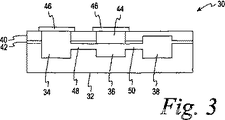
図3は、本発明のもう一つのマイクロ流体装置30を断面図で示す。ベース32が切欠かれて入口34、試薬チャンバ36及び検出チャンバ38を形成している。上部40は、入口34、試薬チャンバ36及び検出チャンバ38の上に開口部を有している。フランジ付き上部によって上層40から吊り下げられ、箔シール46で覆われて装置内で液体試薬を隔離する試薬マイクロリザーバ44を除き、接着層42がベース32又は上部40のいずれかに接着されて装置を完成させている。もう一つの箔シール46が入口34の上に被着されている。
FIG. 3 shows another
使用に際して、箔シール46に開口を形成したのち、試料を入口34に入れる。試料は、毛管48を通って試薬チャンバに入り、チャンバ36中で、マイクロリザーバ44から放出された試薬と反応する。反応した試料は毛管50を通過して検出チャンバ38に入る。上層40は透明なプラスチックでできており、反応の結果を検出チャンバ38から直接、上層40越しに読むことを可能にしている。
In use, an opening is formed in the
Claims (13)
(a)毛管通路によって相互接続された少なくとも2個のチャンバを含有するベース層と、
(b)前記チャンバ及び毛管通路の少なくともいくつかを取り囲むための、前記ベース層の上の上層と、
(c)前記上層を前記ベース層に固着するための、前記ベース層と前記上層との間に配置された接着剤と、
(d)(b)の前記上層によって取り囲まれないチャンバの上に配置された金属化プラスチックフィルムまたは溶融性金属を含む金属箔からなる接着性カバーと、
を含み、
前記ベース層及び前記上層が、それぞれ水分の透過率を1日あたり0.01g/m 2 未満に制限することができる材質及び厚さを有し、
前記少なくとも2個のチャンバの1つが、乾燥試薬または液体試薬である試薬を収容した試薬チャンバとなっており、
前記ベース層が、ポリスチレン、ポリアルキレン、ポリオレフィン類、エポキシ樹脂、PTFE、PET、クロロ−フルオロエチレン類、ポリフッ化ビニリデン、PE−TFE、PE−CTFE、液晶ポリマー、ポリエステル、ポリメチルペンテン、ポリ硫化フェニレン及びPVCからなる群の少なくとも一つのメンバーであり、
前記上層が、ポリプロピレン、PET、ポリエチレン、ポリオレフィン、ポリエステル、ポリスチレンならびにPCTFE、PVC及びポリエステル、ポリオレフィン又はポリアミドを伴うLPCを含む多層材料からなる群の少なくとも一つのメンバーであり、
使用時において、前記試薬チャンバ以外の前記チャンバの上に配置された前記接着性カバーに開口を形成して該開口から試料液を該チャンバに入れると、入れられた前記試料液が前記毛管通路を通って前記試薬チャンバに入り、前記試薬と反応する、マイクロ流体装置。A microfluidic device with a long shelf life for the analysis of biological samples,
(A) a base layer containing at least two chambers interconnected by a capillary passage;
(B) an upper layer on the base layer to surround at least some of the chamber and capillary passage;
(C) before SL upper layer for securing said base layer, adhesive disposed between said upper layer and said base layer,
(D) an adhesive cover comprising a metallized plastic film or a metal foil comprising a meltable metal disposed on a chamber not surrounded by the upper layer of (b);
Including
The base layer and the upper layer each have a material and a thickness that can limit moisture permeability to less than 0.01 g / m 2 per day ,
One of the at least two chambers is a reagent chamber containing a reagent that is a dry reagent or a liquid reagent,
The base layer is made of polystyrene, polyalkylene, polyolefins, epoxy resin, PTFE, PET, chloro-fluoroethylenes, polyvinylidene fluoride, PE-TFE, PE-CTFE, liquid crystal polymer, polyester, polymethylpentene, polyphenylene sulfide. And at least one member of the group consisting of PVC,
The upper layer is at least one member of the group consisting of a multilayer material comprising polypropylene, PET, polyethylene, polyolefin, polyester, polystyrene and LPC with PCTFE, PVC and polyester, polyolefin or polyamide;
In use, when an opening is formed in the adhesive cover disposed on the chamber other than the reagent chamber and a sample solution is put into the chamber from the opening, the sample solution put in the capillary passage. A microfluidic device through which it enters the reagent chamber and reacts with the reagent.
Applications Claiming Priority (3)
| Application Number | Priority Date | Filing Date | Title |
|---|---|---|---|
| US10/447,969 US7435381B2 (en) | 2003-05-29 | 2003-05-29 | Packaging of microfluidic devices |
| US10/447,969 | 2003-05-29 | ||
| PCT/US2004/013394 WO2004105946A2 (en) | 2003-05-29 | 2004-04-30 | Packaging of microfluidic devices |
Publications (2)
| Publication Number | Publication Date |
|---|---|
| JP2007500850A JP2007500850A (en) | 2007-01-18 |
| JP4700004B2 true JP4700004B2 (en) | 2011-06-15 |
Family
ID=33451388
Family Applications (1)
| Application Number | Title | Priority Date | Filing Date |
|---|---|---|---|
| JP2006532520A Active JP4700004B2 (en) | 2003-05-29 | 2004-04-30 | Packaging for microfluidic devices |
Country Status (5)
| Country | Link |
|---|---|
| US (2) | US7435381B2 (en) |
| EP (1) | EP1634071B1 (en) |
| JP (1) | JP4700004B2 (en) |
| CA (1) | CA2527534C (en) |
| WO (1) | WO2004105946A2 (en) |
Families Citing this family (63)
| Publication number | Priority date | Publication date | Assignee | Title |
|---|---|---|---|---|
| US7357898B2 (en) * | 2003-07-31 | 2008-04-15 | Agency For Science, Technology And Research | Microfluidics packages and methods of using same |
| US9518899B2 (en) | 2003-08-11 | 2016-12-13 | Sakura Finetek U.S.A., Inc. | Automated reagent dispensing system and method of operation |
| EP1702952B1 (en) * | 2003-12-19 | 2011-01-12 | Richell Co., Ltd. | Resin composition with excellent thermal transfer properties |
| KR101237662B1 (en) * | 2004-05-07 | 2013-02-26 | 바스프 에스이 | Method for structurally filling contact tubes of a bank of contact tubes |
| EP1838723A4 (en) * | 2004-06-29 | 2008-10-08 | Univ Cincinnati | Polymorphisms and haplotypes of the alpha 2c adrenergic receptor gene |
| US8097225B2 (en) | 2004-07-28 | 2012-01-17 | Honeywell International Inc. | Microfluidic cartridge with reservoirs for increased shelf life of installed reagents |
| BRPI0518969A2 (en) | 2004-12-13 | 2008-12-16 | Bayer Healthcare Llc | independent test sensor |
| US8249681B2 (en) | 2005-01-31 | 2012-08-21 | Given Imaging Ltd. | Device, system and method for in vivo analysis |
| EP1707267A1 (en) * | 2005-03-30 | 2006-10-04 | F. Hoffman-la Roche AG | Device having a self sealing fluid port |
| JP4769027B2 (en) * | 2005-06-17 | 2011-09-07 | 凸版印刷株式会社 | container |
| GB2436616A (en) * | 2006-03-29 | 2007-10-03 | Inverness Medical Switzerland | Assay device and method |
| US8459509B2 (en) | 2006-05-25 | 2013-06-11 | Sakura Finetek U.S.A., Inc. | Fluid dispensing apparatus |
| US20110300034A1 (en) * | 2006-06-19 | 2011-12-08 | The Regents Of The University Of California | Disposable, High Pressure Microfluidic Chips |
| US8123192B2 (en) * | 2006-10-18 | 2012-02-28 | California Institute Of Technology | Control arrangement for microfluidic devices and related methods and systems |
| US7790118B2 (en) * | 2006-10-18 | 2010-09-07 | California Institute Of Technology | Microfluidic devices and related methods and systems |
| GB0621520D0 (en) * | 2006-10-28 | 2006-12-06 | P2I Ltd | Novel products |
| EP1970711A1 (en) * | 2007-03-16 | 2008-09-17 | Radiometer Medical ApS | Reagent cup device |
| US7927866B2 (en) * | 2007-04-19 | 2011-04-19 | American Sterilizer Company | Process challenge device for assessing the effective performance of a biocontamination deactivation process |
| WO2008134462A1 (en) * | 2007-04-25 | 2008-11-06 | 3M Innovative Properties Company | Supported reagents, methods, and devices |
| ES2687620T3 (en) | 2007-05-04 | 2018-10-26 | Opko Diagnostics, Llc | Device and method for analysis in microfluidic systems |
| WO2009035062A1 (en) * | 2007-09-10 | 2009-03-19 | Nec Corporation | Sample packing device |
| WO2010087999A1 (en) | 2009-02-02 | 2010-08-05 | Claros Diagnostics, Inc. | Structures for controlling light interaction with microfluidic devices |
| US20120107811A1 (en) * | 2009-02-06 | 2012-05-03 | Kelso David M | Burstable liquid packaging and uses thereof |
| JP5242465B2 (en) * | 2009-03-18 | 2013-07-24 | 株式会社東芝 | Sample detection device |
| EP2440672B1 (en) | 2009-06-12 | 2016-03-30 | Micronics, Inc. | Compositions and methods for dehydrated storage of on-board reagents in microfluidic devices |
| JP5721704B2 (en) | 2009-06-12 | 2015-05-20 | マイクロニクス, インコーポレイテッド | Rehydratable matrix for dry storage of TAQ polymerase in microfluidic devices |
| US8720036B2 (en) | 2010-03-09 | 2014-05-13 | Netbio, Inc. | Unitary biochip providing sample-in to results-out processing and methods of manufacture |
| NZ721912A (en) * | 2010-03-09 | 2018-01-26 | Netbio Inc | Unitary biochip providing sample-in to results-out processing and methods of manufacture |
| US10670586B2 (en) * | 2010-04-14 | 2020-06-02 | Nitto Boseki Co., Ltd. | Test instrument for measuring analyte in sample by an aggregation assay using a metal colloid and using a reagent attached in a dry state in a reaction chamber, and method for measuring analyte using same |
| EP2558203A1 (en) | 2010-04-16 | 2013-02-20 | Opko Diagnostics, LLC | Systems and devices for analysis of samples |
| US20110312763A1 (en) * | 2010-06-17 | 2011-12-22 | Geneasys Pty Ltd | Genetic analysis loc with in-loc storage of all required reagents |
| US8911689B2 (en) | 2010-07-27 | 2014-12-16 | General Electric Company | Interfacing caps for microfluidic devices and methods of making and using the same |
| DE102010035219A1 (en) | 2010-08-24 | 2012-03-01 | Siemens Healthcare Diagnostics Products Gmbh | Closure device for a reagent container |
| US8752732B2 (en) | 2011-02-01 | 2014-06-17 | Sakura Finetek U.S.A., Inc. | Fluid dispensing system |
| JP2014507669A (en) | 2011-03-08 | 2014-03-27 | ユニベルシテ・ラバル | Fluid centripetal device |
| US9186676B2 (en) | 2011-04-25 | 2015-11-17 | Fujibo Holdings, Inc. | Test reagent container |
| US9196457B2 (en) * | 2011-05-24 | 2015-11-24 | The Trustees Of The University Of Pennsylvania | Flow cells for electron microscope imaging with multiple flow streams |
| WO2013042435A1 (en) * | 2011-09-20 | 2013-03-28 | 富士紡ホールディングス株式会社 | Reagent container |
| US8580568B2 (en) | 2011-09-21 | 2013-11-12 | Sakura Finetek U.S.A., Inc. | Traceability for automated staining system |
| US8932543B2 (en) | 2011-09-21 | 2015-01-13 | Sakura Finetek U.S.A., Inc. | Automated staining system and reaction chamber |
| CN104364788B (en) | 2012-03-05 | 2018-02-06 | 阿克蒂克合伙公司 | Predict prostate cancer risk and the device of prostate gland volume |
| WO2013172003A1 (en) | 2012-05-16 | 2013-11-21 | パナソニック株式会社 | Organism detection chip and organism detection device provided therewith |
| CN104508451A (en) * | 2012-08-06 | 2015-04-08 | 维韦比奥有限责任公司 | Matrix and system for preserving biological specimens for qualitative and quantitative analysis |
| CN104870092A (en) * | 2012-11-29 | 2015-08-26 | 皇家飞利浦有限公司 | Cartridge for uptake and processing of a sample |
| FR3000215B1 (en) * | 2012-12-21 | 2016-02-05 | Aneolia | DEVICE AND METHOD FOR TESTING A SAMPLE, ESPECIALLY DISCRIMINATION OF A GAS FROM A SAMPLE |
| KR102435654B1 (en) | 2013-03-11 | 2022-08-25 | 큐 헬스 인코퍼레이티드 | Systems and methods for detection and quantification of analytes |
| US20160003815A1 (en) * | 2013-03-15 | 2016-01-07 | Inanovate, Inc. | Method, system, and device for analyte detection and measurement using longitudinal assay |
| WO2015045134A1 (en) * | 2013-09-30 | 2015-04-02 | 株式会社日立製作所 | Reagent holding container, liquid delivery device, and reagent discharge method |
| US9399216B2 (en) | 2013-12-30 | 2016-07-26 | General Electric Company | Fluid transport in microfluidic applications with sensors for detecting fluid presence and pressure |
| US10076751B2 (en) * | 2013-12-30 | 2018-09-18 | General Electric Company | Systems and methods for reagent storage |
| JP2015171754A (en) * | 2014-03-12 | 2015-10-01 | 大日本印刷株式会社 | Micro flow passage device |
| USD745423S1 (en) | 2014-05-12 | 2015-12-15 | Cue Inc. | Automated analyzer test cartridge and sample collection device for analyte detection |
| US10634602B2 (en) | 2015-06-12 | 2020-04-28 | Cytochip Inc. | Fluidic cartridge for cytometry and additional analysis |
| CA3224549A1 (en) | 2015-07-17 | 2017-01-26 | Cue Health Inc. | Systems and methods for enhanced detection and quantification of analytes |
| USD799715S1 (en) | 2015-10-23 | 2017-10-10 | Gene POC, Inc. | Fluidic centripetal device |
| US20190240655A1 (en) * | 2016-09-14 | 2019-08-08 | Sekisui Chemical Co., Ltd. | Microchip |
| US11237161B2 (en) | 2017-01-25 | 2022-02-01 | Cue Health Inc. | Systems and methods for enhanced detection and quantification of analytes |
| CN110621406B (en) * | 2017-05-11 | 2022-02-22 | 芯易诊有限公司 | Reagent packaging device and application thereof |
| WO2019083844A1 (en) | 2017-10-23 | 2019-05-02 | Cytochip Inc. | Devices and methods for measuring analytes and target particles |
| GB201901499D0 (en) * | 2019-02-04 | 2019-03-27 | Innospec Ltd | Polymeric materials |
| USD975312S1 (en) | 2020-02-14 | 2023-01-10 | Beckman Coulter, Inc. | Reagent cartridge |
| GB202017920D0 (en) * | 2020-11-13 | 2020-12-30 | Ttp Plc | Sample analysis cartridge |
| US20220331802A1 (en) * | 2021-04-16 | 2022-10-20 | The Regents Of The University Of California | Burstable liquid storage package for biological materials and valve substitution |
Citations (2)
| Publication number | Priority date | Publication date | Assignee | Title |
|---|---|---|---|---|
| JPH11511237A (en) * | 1995-03-17 | 1999-09-28 | ユニリーバー・ナームローゼ・ベンノートシヤープ | Testing device |
| JP2002098661A (en) * | 2000-07-20 | 2002-04-05 | F Hoffmann-La Roche Ag | Reclosable biosensor |
Family Cites Families (125)
| Publication number | Priority date | Publication date | Assignee | Title |
|---|---|---|---|---|
| US3799742A (en) * | 1971-12-20 | 1974-03-26 | C Coleman | Miniaturized integrated analytical test container |
| US3798459A (en) * | 1972-10-06 | 1974-03-19 | Atomic Energy Commission | Compact dynamic multistation photometer utilizing disposable cuvette rotor |
| US3804533A (en) * | 1972-11-29 | 1974-04-16 | Atomic Energy Commission | Rotor for fluorometric measurements in fast analyzer of rotary |
| US3856649A (en) | 1973-03-16 | 1974-12-24 | Miles Lab | Solid state electrode |
| US4310399A (en) * | 1979-07-23 | 1982-01-12 | Eastman Kodak Company | Liquid transport device containing means for delaying capillary flow |
| US4436610A (en) * | 1980-12-15 | 1984-03-13 | Transidyne General Corporation | Apparatus for measuring electrochemical activity |
| US4587220A (en) * | 1983-03-28 | 1986-05-06 | Miles Laboratories, Inc. | Ascorbate interference-resistant composition, device and method for the determination of peroxidatively active substances |
| JPS6077768A (en) * | 1983-10-06 | 1985-05-02 | テルモ株式会社 | Liquid dialytic apparatus |
| US4534659A (en) * | 1984-01-27 | 1985-08-13 | Millipore Corporation | Passive fluid mixing system |
| US4618476A (en) * | 1984-02-10 | 1986-10-21 | Eastman Kodak Company | Capillary transport device having speed and meniscus control means |
| US4676274A (en) * | 1985-02-28 | 1987-06-30 | Brown James F | Capillary flow control |
| US4963498A (en) * | 1985-08-05 | 1990-10-16 | Biotrack | Capillary flow device |
| US5164598A (en) | 1985-08-05 | 1992-11-17 | Biotrack | Capillary flow device |
| US4755472A (en) * | 1986-01-16 | 1988-07-05 | Miles Inc. | Stable composition for the determination of peroxidatively active substances |
| DE3721237A1 (en) * | 1987-06-27 | 1989-01-05 | Boehringer Mannheim Gmbh | DIAGNOSTIC TEST CARRIER AND METHOD FOR THE PRODUCTION THEREOF |
| US5372918A (en) | 1988-03-11 | 1994-12-13 | Fuji Photo Film Co., Ltd. | Method of processing a silver halide color reversal photographic light-sensitive material |
| US4908112A (en) * | 1988-06-16 | 1990-03-13 | E. I. Du Pont De Nemours & Co. | Silicon semiconductor wafer for analyzing micronic biological samples |
| US5096669A (en) * | 1988-09-15 | 1992-03-17 | I-Stat Corporation | Disposable sensing device for real time fluid analysis |
| US5939272A (en) * | 1989-01-10 | 1999-08-17 | Biosite Diagnostics Incorporated | Non-competitive threshold ligand-receptor assays |
| US5160702A (en) | 1989-01-17 | 1992-11-03 | Molecular Devices Corporation | Analyzer with improved rotor structure |
| US5024647A (en) * | 1989-06-13 | 1991-06-18 | The United States Of America As Represented By The United States Department Of Energy | Centrifugal contactor with liquid mixing and flow control vanes and method of mixing liquids of different phases |
| US5089420A (en) * | 1990-01-30 | 1992-02-18 | Miles Inc. | Composition, device and method of assaying for a peroxidatively active substance utilizing amine borate compounds |
| US5318894A (en) * | 1990-01-30 | 1994-06-07 | Miles Inc. | Composition, device and method of assaying for peroxidatively active substances |
| US5922615A (en) * | 1990-03-12 | 1999-07-13 | Biosite Diagnostics Incorporated | Assay devices comprising a porous capture membrane in fluid-withdrawing contact with a nonabsorbent capillary network |
| CA2072758A1 (en) | 1990-09-14 | 1992-03-15 | Kenneth Francis Buechler | Antibodies to complexes of ligand receptors and ligands and their utility in ligand-receptor assays |
| DE59108006D1 (en) * | 1991-01-28 | 1996-08-22 | Ciba Geigy Ag | Device for the preparation of samples, in particular for analysis purposes |
| SE9100392D0 (en) * | 1991-02-08 | 1991-02-08 | Pharmacia Biosensor Ab | A METHOD OF PRODUCING A SEALING MEANS IN A MICROFLUIDIC STRUCTURE AND A MICROFLUIDIC STRUCTURE COMPRISING SUCH SEALING MEANS |
| WO1992018866A1 (en) | 1991-04-10 | 1992-10-29 | Biosite Diagnostics Incorporated | Novel conjugates and assays for simultaneous detection of multiple ligands |
| US5187104A (en) * | 1991-06-06 | 1993-02-16 | Miles Inc. | Nitro or nitroso substituted polyhalogenated phenolsulfonephthaleins as protein indicators in biological samples |
| DE69213826T2 (en) * | 1991-06-06 | 1997-01-30 | Bayer Ag | Test strips with merocyanine and nitro or nitroso substituted polyhalogenated phenolsulfonphthaleins as protein indicators |
| US6100099A (en) * | 1994-09-06 | 2000-08-08 | Abbott Laboratories | Test strip having a diagonal array of capture spots |
| US5296192A (en) * | 1992-04-03 | 1994-03-22 | Home Diagnostics, Inc. | Diagnostic test strip |
| US5222808A (en) * | 1992-04-10 | 1993-06-29 | Biotrack, Inc. | Capillary mixing device |
| US5637469A (en) * | 1992-05-01 | 1997-06-10 | Trustees Of The University Of Pennsylvania | Methods and apparatus for the detection of an analyte utilizing mesoscale flow systems |
| US6143576A (en) | 1992-05-21 | 2000-11-07 | Biosite Diagnostics, Inc. | Non-porous diagnostic devices for the controlled movement of reagents |
| US6019944A (en) * | 1992-05-21 | 2000-02-01 | Biosite Diagnostics, Inc. | Diagnostic devices and apparatus for the controlled movement of reagents without membranes |
| US5290518A (en) * | 1992-08-17 | 1994-03-01 | Eastman Kodak Company | Flexible extraction device with burstable sidewall |
| US6037455A (en) * | 1992-11-09 | 2000-03-14 | Biosite Diagnostics Incorporated | Propoxyphene derivatives and protein and polypeptide propoxyphene derivative conjugates and labels |
| DE4303923A1 (en) * | 1993-02-10 | 1994-08-11 | Microparts Gmbh | Process for removing plastics from microstructures |
| US5529681A (en) * | 1993-03-30 | 1996-06-25 | Microparts Gesellschaft Fur Mikrostrukturtechnik Mbh | Stepped mould inserts, high-precision stepped microstructure bodies, and methods of producing the same |
| US6043043A (en) * | 1993-04-02 | 2000-03-28 | Bayer Corporation | Method for the determination of hemoglobin adducts |
| US5360595A (en) | 1993-08-19 | 1994-11-01 | Miles Inc. | Preparation of diagnostic test strips containing tetrazolium salt indicators |
| US5478751A (en) | 1993-12-29 | 1995-12-26 | Abbott Laboratories | Self-venting immunodiagnositic devices and methods of performing assays |
| US5424125A (en) * | 1994-04-11 | 1995-06-13 | Shakespeare Company | Monofilaments from polymer blends and fabrics thereof |
| US5627041A (en) * | 1994-09-02 | 1997-05-06 | Biometric Imaging, Inc. | Disposable cartridge for an assay of a biological sample |
| US5834314A (en) | 1994-11-07 | 1998-11-10 | Abbott Laboratories | Method and apparatus for metering a fluid |
| US5571684A (en) | 1994-11-07 | 1996-11-05 | Litmus Concepts, Inc. | Assay for proline iminopeptidase and other hydrolytic activities |
| US5585069A (en) | 1994-11-10 | 1996-12-17 | David Sarnoff Research Center, Inc. | Partitioned microelectronic and fluidic device array for clinical diagnostics and chemical synthesis |
| DE19520298A1 (en) | 1995-06-02 | 1996-12-05 | Bayer Ag | Sorting device for biological cells or viruses |
| US6130098A (en) | 1995-09-15 | 2000-10-10 | The Regents Of The University Of Michigan | Moving microdroplets |
| DE19536856C2 (en) * | 1995-10-03 | 1997-08-21 | Danfoss As | Micromixer and mixing process |
| DE19536901A1 (en) * | 1995-10-04 | 1997-04-10 | Microparts Gmbh | Process for producing integrated electrodes in plastic molds, plastic molds with integrated electrodes and their use |
| DE19540292C1 (en) * | 1995-10-28 | 1997-01-30 | Karlsruhe Forschzent | Static micromixer |
| DE19541266A1 (en) * | 1995-11-06 | 1997-05-07 | Bayer Ag | Method and device for carrying out chemical reactions using a microstructure lamella mixer |
| DE19604289C2 (en) * | 1996-02-07 | 1998-04-23 | Danfoss As | Micromixer |
| US6399023B1 (en) * | 1996-04-16 | 2002-06-04 | Caliper Technologies Corp. | Analytical system and method |
| US5942443A (en) * | 1996-06-28 | 1999-08-24 | Caliper Technologies Corporation | High throughput screening assay systems in microscale fluidic devices |
| US5885470A (en) * | 1997-04-14 | 1999-03-23 | Caliper Technologies Corporation | Controlled fluid transport in microfabricated polymeric substrates |
| AU726987B2 (en) * | 1996-06-28 | 2000-11-30 | Caliper Life Sciences, Inc. | Electropipettor and compensation means for electrophoretic bias |
| US5800690A (en) | 1996-07-03 | 1998-09-01 | Caliper Technologies Corporation | Variable control of electroosmotic and/or electrophoretic forces within a fluid-containing structure via electrical forces |
| US5826981A (en) * | 1996-08-26 | 1998-10-27 | Nova Biomedical Corporation | Apparatus for mixing laminar and turbulent flow streams |
| US6113855A (en) * | 1996-11-15 | 2000-09-05 | Biosite Diagnostics, Inc. | Devices comprising multiple capillarity inducing surfaces |
| US6447727B1 (en) * | 1996-11-19 | 2002-09-10 | Caliper Technologies Corp. | Microfluidic systems |
| WO1998032526A1 (en) * | 1997-01-24 | 1998-07-30 | The Regents Of The University Of California | Apparatus and method for planar laminar mixing |
| EP1030733A1 (en) * | 1997-02-05 | 2000-08-30 | California Institute Of Technology | Microfluidic sub-millisecond mixers |
| HUP0003152A3 (en) * | 1997-02-28 | 2002-09-30 | Burstein Lab Inc Irvine | Laboratory in a disk |
| US5964995A (en) | 1997-04-04 | 1999-10-12 | Caliper Technologies Corp. | Methods and systems for enhanced fluid transport |
| US5965375A (en) | 1997-04-04 | 1999-10-12 | Biosite Diagnostics | Diagnostic tests and kits for Clostridium difficile |
| DE19716073A1 (en) * | 1997-04-17 | 1998-10-22 | Boehringer Mannheim Gmbh | Dosing device for dispensing small amounts of liquid |
| WO1998049548A1 (en) * | 1997-04-25 | 1998-11-05 | Caliper Technologies Corporation | Microfluidic devices incorporating improved channel geometries |
| US5976336A (en) | 1997-04-25 | 1999-11-02 | Caliper Technologies Corp. | Microfluidic devices incorporating improved channel geometries |
| US5932315A (en) * | 1997-04-30 | 1999-08-03 | Hewlett-Packard Company | Microfluidic structure assembly with mating microfeatures |
| JP3469585B2 (en) * | 1997-05-23 | 2003-11-25 | ガメラ バイオサイエンス コーポレイション | Apparatus and method for using centripetal acceleration to drive flow motion in microfluidics systems |
| US6090251A (en) * | 1997-06-06 | 2000-07-18 | Caliper Technologies, Inc. | Microfabricated structures for facilitating fluid introduction into microfluidic devices |
| US5869004A (en) | 1997-06-09 | 1999-02-09 | Caliper Technologies Corp. | Methods and apparatus for in situ concentration and/or dilution of materials in microfluidic systems |
| US5959291A (en) * | 1997-06-27 | 1999-09-28 | Caliper Technologies Corporation | Method and apparatus for measuring low power signals |
| US6001231A (en) | 1997-07-15 | 1999-12-14 | Caliper Technologies Corp. | Methods and systems for monitoring and controlling fluid flow rates in microfluidic systems |
| US5876675A (en) * | 1997-08-05 | 1999-03-02 | Caliper Technologies Corp. | Microfluidic devices and systems |
| US6002475A (en) | 1998-01-28 | 1999-12-14 | Careside, Inc. | Spectrophotometric analytical cartridge |
| US5989402A (en) | 1997-08-29 | 1999-11-23 | Caliper Technologies Corp. | Controller/detector interfaces for microfluidic systems |
| US5965410A (en) | 1997-09-02 | 1999-10-12 | Caliper Technologies Corp. | Electrical current for controlling fluid parameters in microchannels |
| DE19741492A1 (en) * | 1997-09-19 | 1999-03-25 | Microparts Gmbh | Process for the production of microstructure bodies |
| CA2301557A1 (en) * | 1997-09-19 | 1999-04-01 | Aclara Biosciences, Inc. | Apparatus and method for transferring liquids |
| US6012902A (en) * | 1997-09-25 | 2000-01-11 | Caliper Technologies Corp. | Micropump |
| US6136272A (en) | 1997-09-26 | 2000-10-24 | University Of Washington | Device for rapidly joining and splitting fluid layers |
| US6106779A (en) * | 1997-10-02 | 2000-08-22 | Biosite Diagnostics, Inc. | Lysis chamber for use in an assay device |
| US5842787A (en) * | 1997-10-09 | 1998-12-01 | Caliper Technologies Corporation | Microfluidic systems incorporating varied channel dimensions |
| US5958694A (en) * | 1997-10-16 | 1999-09-28 | Caliper Technologies Corp. | Apparatus and methods for sequencing nucleic acids in microfluidic systems |
| CA2307623C (en) * | 1997-11-12 | 2004-03-16 | The Perkin-Elmer Corporation | Serpentine electrophoresis channel with self-correcting bends |
| US5994150A (en) | 1997-11-19 | 1999-11-30 | Imation Corp. | Optical assaying method and system having rotatable sensor disk with multiple sensing regions |
| US6074725A (en) * | 1997-12-10 | 2000-06-13 | Caliper Technologies Corp. | Fabrication of microfluidic circuits by printing techniques |
| DE19755529A1 (en) * | 1997-12-13 | 1999-06-17 | Roche Diagnostics Gmbh | Analysis system for sample liquids |
| US5948227A (en) * | 1997-12-17 | 1999-09-07 | Caliper Technologies Corp. | Methods and systems for performing electrophoretic molecular separations |
| US6167910B1 (en) * | 1998-01-20 | 2001-01-02 | Caliper Technologies Corp. | Multi-layer microfluidic devices |
| US6100541A (en) * | 1998-02-24 | 2000-08-08 | Caliper Technologies Corporation | Microfluidic devices and systems incorporating integrated optical elements |
| DE19815684A1 (en) * | 1998-04-08 | 1999-10-14 | Roche Diagnostics Gmbh | Process for the preparation of analytical aids |
| US6123798A (en) * | 1998-05-06 | 2000-09-26 | Caliper Technologies Corp. | Methods of fabricating polymeric structures incorporating microscale fluidic elements |
| WO1999056862A1 (en) * | 1998-05-07 | 1999-11-11 | Purdue Research Foundation | An in situ micromachined mixer for microfluidic analytical systems |
| DE69800630T2 (en) * | 1998-07-29 | 2001-08-23 | Agilent Technologies Inc | Chip for electrophoretic separation of molecules and method for using the same |
| US6540896B1 (en) * | 1998-08-05 | 2003-04-01 | Caliper Technologies Corp. | Open-Field serial to parallel converter |
| US6132685A (en) | 1998-08-10 | 2000-10-17 | Caliper Technologies Corporation | High throughput microfluidic systems and methods |
| JP3012608B1 (en) * | 1998-09-17 | 2000-02-28 | 農林水産省食品総合研究所長 | Microchannel device and method for producing emulsion using the same |
| US6086740A (en) | 1998-10-29 | 2000-07-11 | Caliper Technologies Corp. | Multiplexed microfluidic devices and systems |
| US6136610A (en) | 1998-11-23 | 2000-10-24 | Praxsys Biosystems, Inc. | Method and apparatus for performing a lateral flow assay |
| US6185029B1 (en) * | 1998-12-25 | 2001-02-06 | Canon Kabushiki Kaisha | Optical scanner and electrophotographic printer employing the same |
| US6150119A (en) | 1999-01-19 | 2000-11-21 | Caliper Technologies Corp. | Optimized high-throughput analytical system |
| US6148508A (en) | 1999-03-12 | 2000-11-21 | Caliper Technologies Corp. | Method of making a capillary for electrokinetic transport of materials |
| ATE272213T1 (en) * | 1999-06-18 | 2004-08-15 | Gamera Bioscience Corp | DEVICES AND METHODS FOR PERFORMING MINIATURIZED HOMOGENEOUS TESTS |
| EP1250602A2 (en) * | 1999-08-06 | 2002-10-23 | Thermo Biostar, Inc. | An automated point of care detection system including complete sample processing capabilities |
| DE60035199T2 (en) * | 1999-08-11 | 2008-02-14 | Asahi Kasei Kabushiki Kaisha | ANALYSIS CASSETTE AND LIQUID CONVEYOR CONTROLLER |
| US6547468B2 (en) * | 2001-06-22 | 2003-04-15 | The Procter & Gamble Company | Dosing reservoir |
| US6875619B2 (en) * | 1999-11-12 | 2005-04-05 | Motorola, Inc. | Microfluidic devices comprising biochannels |
| US20020112961A1 (en) * | 1999-12-02 | 2002-08-22 | Nanostream, Inc. | Multi-layer microfluidic device fabrication |
| JP2003533682A (en) * | 2000-05-15 | 2003-11-11 | テカン・トレーディング・アクチェンゲゼルシャフト | Bidirectional flow centrifugal microfluidic device |
| US6428664B1 (en) * | 2000-06-19 | 2002-08-06 | Roche Diagnostics Corporation | Biosensor |
| WO2002001081A2 (en) * | 2000-06-23 | 2002-01-03 | Micronics, Inc. | Valve for use in microfluidic structures |
| US6734401B2 (en) * | 2000-06-28 | 2004-05-11 | 3M Innovative Properties Company | Enhanced sample processing devices, systems and methods |
| EP1334347A1 (en) * | 2000-09-15 | 2003-08-13 | California Institute Of Technology | Microfabricated crossflow devices and methods |
| WO2002022267A2 (en) * | 2000-09-18 | 2002-03-21 | Micronics, Inc. | Externally controllable surface coatings for microfluidic devices |
| WO2002023161A1 (en) * | 2000-09-18 | 2002-03-21 | University Of Washington | Microfluidic devices for rotational manipulation of the fluidic interface between multiple flow streams |
| US6939451B2 (en) * | 2000-09-19 | 2005-09-06 | Aclara Biosciences, Inc. | Microfluidic chip having integrated electrodes |
| DE50110742D1 (en) * | 2000-10-25 | 2006-09-28 | Boehringer Ingelheim Micropart | Microstructured platform for studying a liquid |
| US20060207877A1 (en) * | 2001-01-30 | 2006-09-21 | Walter Schmidt | Microfluidic device with various surface properties fabricated in multilayer body by plasma etching |
| US6949377B2 (en) * | 2001-03-05 | 2005-09-27 | Ho Winston Z | Chemiluminescence-based microfluidic biochip |
| SE0104077D0 (en) * | 2001-10-21 | 2001-12-05 | Gyros Ab | A method and instrumentation for micro dispensation of droplets |
-
2003
- 2003-05-29 US US10/447,969 patent/US7435381B2/en not_active Expired - Lifetime
-
2004
- 2004-04-30 CA CA2527534A patent/CA2527534C/en active Active
- 2004-04-30 EP EP04785625.7A patent/EP1634071B1/en active Active
- 2004-04-30 WO PCT/US2004/013394 patent/WO2004105946A2/en active Application Filing
- 2004-04-30 JP JP2006532520A patent/JP4700004B2/en active Active
-
2008
- 2008-09-08 US US12/205,949 patent/US20090041627A1/en not_active Abandoned
Patent Citations (2)
| Publication number | Priority date | Publication date | Assignee | Title |
|---|---|---|---|---|
| JPH11511237A (en) * | 1995-03-17 | 1999-09-28 | ユニリーバー・ナームローゼ・ベンノートシヤープ | Testing device |
| JP2002098661A (en) * | 2000-07-20 | 2002-04-05 | F Hoffmann-La Roche Ag | Reclosable biosensor |
Also Published As
| Publication number | Publication date |
|---|---|
| CA2527534C (en) | 2013-08-13 |
| EP1634071A2 (en) | 2006-03-15 |
| CA2527534A1 (en) | 2004-12-09 |
| US20090041627A1 (en) | 2009-02-12 |
| WO2004105946A3 (en) | 2005-08-11 |
| US7435381B2 (en) | 2008-10-14 |
| EP1634071A4 (en) | 2012-01-25 |
| US20040241042A1 (en) | 2004-12-02 |
| JP2007500850A (en) | 2007-01-18 |
| WO2004105946A2 (en) | 2004-12-09 |
| EP1634071B1 (en) | 2019-07-10 |
Similar Documents
| Publication | Publication Date | Title |
|---|---|---|
| JP4700004B2 (en) | Packaging for microfluidic devices | |
| JP3418174B2 (en) | Analytical test element with capillary channel | |
| US8252248B2 (en) | Analytical test element | |
| CN101147057B (en) | Test element for analysing body fluids | |
| EP1203959B1 (en) | Analyzing cartridge and liquid feed control device | |
| CA2267919C (en) | Process for the production of analytical devices | |
| JP5833755B2 (en) | Diagnostic test cartridge | |
| EP3311160B1 (en) | A plasma separating microfluidic device | |
| WO1998040735A1 (en) | Testing instrument for analyzing liquid sample | |
| JPWO2002084291A1 (en) | Sample analysis tools | |
| AU3263199A (en) | Apparatus for, and method of, varying the rate of flow of fluid along a pathway | |
| JP2006292742A (en) | Device having self-sealing fluid port | |
| US20110027873A1 (en) | Micro-nano fluidic biochip for assaying biological sample | |
| US20160038939A1 (en) | Microfluidic device | |
| US10514354B2 (en) | Biosensor structures for improved point of care testing and methods of manufacture thereof | |
| JPS61153566A (en) | Reagent testing tool and forming method thereof | |
| JPH01202661A (en) | Flow intensifying dip stick | |
| WO2018033609A1 (en) | A microfluidic device | |
| US20130066171A1 (en) | Lancet Magazine and Method for the Production Thereof | |
| JP2019074351A (en) | Inspection device | |
| US11859734B2 (en) | Valve for microfluidic device | |
| JP7351354B2 (en) | concentration device | |
| CN115920987A (en) | Drug sensitivity detection chip based on bacteria enrichment | |
| CZ20002021A3 (en) | Analytic testing element with capillary channel |
Legal Events
| Date | Code | Title | Description |
|---|---|---|---|
| A621 | Written request for application examination |
Free format text: JAPANESE INTERMEDIATE CODE: A621 Effective date: 20070425 |
|
| A977 | Report on retrieval |
Free format text: JAPANESE INTERMEDIATE CODE: A971007 Effective date: 20090612 |
|
| A131 | Notification of reasons for refusal |
Free format text: JAPANESE INTERMEDIATE CODE: A131 Effective date: 20091020 |
|
| A521 | Request for written amendment filed |
Free format text: JAPANESE INTERMEDIATE CODE: A523 Effective date: 20100119 |
|
| A131 | Notification of reasons for refusal |
Free format text: JAPANESE INTERMEDIATE CODE: A131 Effective date: 20100622 |
|
| A601 | Written request for extension of time |
Free format text: JAPANESE INTERMEDIATE CODE: A601 Effective date: 20100922 |
|
| A602 | Written permission of extension of time |
Free format text: JAPANESE INTERMEDIATE CODE: A602 Effective date: 20100930 |
|
| A711 | Notification of change in applicant |
Free format text: JAPANESE INTERMEDIATE CODE: A711 Effective date: 20101008 |
|
| A601 | Written request for extension of time |
Free format text: JAPANESE INTERMEDIATE CODE: A601 Effective date: 20101021 |
|
| A602 | Written permission of extension of time |
Free format text: JAPANESE INTERMEDIATE CODE: A602 Effective date: 20101101 |
|
| A521 | Request for written amendment filed |
Free format text: JAPANESE INTERMEDIATE CODE: A523 Effective date: 20101108 |
|
| A131 | Notification of reasons for refusal |
Free format text: JAPANESE INTERMEDIATE CODE: A131 Effective date: 20101214 |
|
| A521 | Request for written amendment filed |
Free format text: JAPANESE INTERMEDIATE CODE: A523 Effective date: 20110106 |
|
| TRDD | Decision of grant or rejection written | ||
| A01 | Written decision to grant a patent or to grant a registration (utility model) |
Free format text: JAPANESE INTERMEDIATE CODE: A01 Effective date: 20110201 |
|
| A61 | First payment of annual fees (during grant procedure) |
Free format text: JAPANESE INTERMEDIATE CODE: A61 Effective date: 20110303 |
|
| R150 | Certificate of patent or registration of utility model |
Ref document number: 4700004 Country of ref document: JP Free format text: JAPANESE INTERMEDIATE CODE: R150 |
|
| R250 | Receipt of annual fees |
Free format text: JAPANESE INTERMEDIATE CODE: R250 |
|
| R250 | Receipt of annual fees |
Free format text: JAPANESE INTERMEDIATE CODE: R250 |
|
| R250 | Receipt of annual fees |
Free format text: JAPANESE INTERMEDIATE CODE: R250 |
|
| R250 | Receipt of annual fees |
Free format text: JAPANESE INTERMEDIATE CODE: R250 |
|
| R250 | Receipt of annual fees |
Free format text: JAPANESE INTERMEDIATE CODE: R250 |
|
| R250 | Receipt of annual fees |
Free format text: JAPANESE INTERMEDIATE CODE: R250 |
|
| R250 | Receipt of annual fees |
Free format text: JAPANESE INTERMEDIATE CODE: R250 |
|
| R250 | Receipt of annual fees |
Free format text: JAPANESE INTERMEDIATE CODE: R250 |
|
| R250 | Receipt of annual fees |
Free format text: JAPANESE INTERMEDIATE CODE: R250 |
|
| R250 | Receipt of annual fees |
Free format text: JAPANESE INTERMEDIATE CODE: R250 |
|
| R250 | Receipt of annual fees |
Free format text: JAPANESE INTERMEDIATE CODE: R250 |