JP4699397B2 - Game machine - Google Patents
Game machine Download PDFInfo
- Publication number
- JP4699397B2 JP4699397B2 JP2007019602A JP2007019602A JP4699397B2 JP 4699397 B2 JP4699397 B2 JP 4699397B2 JP 2007019602 A JP2007019602 A JP 2007019602A JP 2007019602 A JP2007019602 A JP 2007019602A JP 4699397 B2 JP4699397 B2 JP 4699397B2
- Authority
- JP
- Japan
- Prior art keywords
- gaming machine
- main body
- base member
- gaming
- game board
- Prior art date
- Legal status (The legal status is an assumption and is not a legal conclusion. Google has not performed a legal analysis and makes no representation as to the accuracy of the status listed.)
- Expired - Fee Related
Links
Images


Landscapes
- Pinball Game Machines (AREA)
Description
本発明は、遊技盤と、該遊技盤が取り付けられるベース部材と、ベース部材に軸着される前面扉とから構成される分離ユニットと、この分離ユニットが前面側に着脱される遊技機本体とから構成された遊技機に関するものである。 The present invention relates to a separation unit comprising a game board, a base member to which the game board is attached, and a front door pivotally attached to the base member, and a gaming machine main body to which the separation unit is attached to and detached from the front side. It is related with the game machine comprised from this.
パチンコ店などの遊技場に配設される遊技機として、スロットマシンやパチンコ機などが挙げられる。このパチンコ機は、基体となる本体部材(遊技機本体)に、パチンコ球が打ち出される遊技領域が設けられた遊技盤が取り付けられる他に、遊技領域を遊技者に視認させる開口を備えた前面扉が軸着されている。また、本体部材には、パチンコ機に給電を行う電源装置や、パチンコ球を打ち出す発射装置、パチンコ球を払い出す払出装置や、これらの作動を制御する制御回路基板などが取り付けられている。 As a gaming machine arranged in a game hall such as a pachinko parlor, a slot machine or a pachinko machine can be cited. This pachinko machine has a main body member (game machine main body) as a base with a game board provided with a game area where a pachinko ball is launched, and a front door provided with an opening that allows a player to visually recognize the game area Is attached. In addition, a power supply device that supplies power to the pachinko machine, a launching device that launches pachinko balls, a payout device that dispenses pachinko balls, a control circuit board that controls these operations, and the like are attached to the main body member.
遊技場においては、既に配設されたパチンコ機から、新しい機種のパチンコ機へ交換する、所謂機種替えを行うときには、遊技場に配設されたパチンコ機を固定枠毎取り外した後、新しい機種となるパチンコ機を遊技場に配設することが一般的に行われている。このような機種替えのうち、遊技場から取り外されたパチンコ機と新たに遊技場に配設するパチンコ機とが同一の製造者の元で作成されたものであっても、遊技場に配設されていたパチンコ機は取り外されることが多く、例えば同一形状の本体部材や、この本体部材に取り付けられる発射装置や払出装置など、共通化できるものまで交換してしまうことになり、機種替えにかかる設備投資のコストダウンを効率良く行うことができないという問題がある。 In the amusement hall, when replacing a pachinko machine already installed with a new model of a pachinko machine, so-called model change, after removing the pachinko machine installed in the amusement hall for each fixed frame, It is a common practice to arrange a pachinko machine in a game hall. Among such model changes, even if the pachinko machine removed from the amusement hall and the pachinko machine newly installed in the amusement hall were created under the same manufacturer, they were placed in the amusement hall Pachinko machines that have been used are often removed. For example, the same shape of the main body member, the launching device attached to this main body member, the dispensing device, etc. will be replaced, and it will take a model change. There is a problem that the cost of capital investment cannot be efficiently reduced.
このような問題を解決する方法として、発射装置や払出装置などパチンコ機の基本動作を行う装置や本体部材を遊技場に据え置きとし、遊技盤や前面扉、及び遊技を制御する遊技制御回路装置など交換が必要な箇所のみを本体部材からまとめて交換できる分離ユニットとすることが提案されている(特許文献など)。このように、同一の製造者の元で製造されたパチンコ機であれば、分離ユニットのみを交換することが可能となり、機種替え時に係る設備投資のコストダウンを効率良く行うことができる。
上述した分離ユニットは、前面扉が軸着されるベース部材に遊技盤を取り付けていることで構成されていることが多い。このベース部材としては、遊技盤の四隅を係止機構等によって遊技盤を取り付ける枠状のものが一般的に用いられているが、最近では、アニメーション表示等の動画表示や、当たり表示などを行う図柄表示装置が拡大傾向に有り、遊技盤や、遊技盤に設けられる遊技領域が拡大されていることから、ベース部材の小型化が望まれる。しかしながら、従来のベース部材や、小型化されたベース部材を遊技機本体に取り付けた場合には、ベース部材の軸側では、その前後方向において遊技機本体に対する相対的な位置精度が低くなることから、打ち出されたパチンコ球が遊技盤に接触して軌道が変化してしまう原因となる。パチンコ球の軌道が変化してしまうと遊技を正常に行うことができないことから、遊技機本体に対する遊技機の位置精度を高精度とするためには、遊技機本体に分離ユニットを取り付けた後に、遊技盤の位置決めや位置精度の測定を行う必要があり、製造コストが上昇する要因となりやすい。 The separation unit described above is often configured by attaching a game board to a base member on which a front door is pivotally attached. As this base member, a frame-shaped member in which a game board is attached to the four corners of the game board by a locking mechanism or the like is generally used. Recently, however, animation display or other animation display or hit display is performed. Since the symbol display device tends to expand and the game board and the game area provided on the game board are expanded, it is desired to reduce the size of the base member. However, when a conventional base member or a miniaturized base member is attached to the gaming machine main body, the relative positional accuracy with respect to the gaming machine main body in the front-rear direction is lowered on the shaft side of the base member. The pachinko ball that is launched contacts the game board and causes the trajectory to change. If the pachinko ball trajectory changes, it will not be possible to play games normally, so in order to increase the positional accuracy of the gaming machine relative to the gaming machine body, after attaching the separation unit to the gaming machine body, It is necessary to position the game board and measure the position accuracy, which tends to increase the manufacturing cost.
本発明は、上記課題を解決するためになされたものであり、遊技機本体に対する遊技盤の位置決めを容易にできるようにし、かつパチンコ球の発射軌道の精度を向上させる遊技機を提供することを目的とする。 The present invention has been made to solve the above problems, and provides a gaming machine that facilitates the positioning of the gaming board with respect to the gaming machine body and that improves the accuracy of the pachinko ball launching trajectory. Objective.
上記目的を達成するために、本発明の遊技機は、パチンコ球が流下する遊技領域を有する遊技盤と、前記遊技盤が取り付けられるベース部材と、前記遊技盤が取り付けられた前記ベース部材を収納する遊技機本体とを備えた遊技機において、前記ベース部材に設けられ、前記遊技盤の幅方向の一端部を仮保持する保持部材と、前記ベース部材に仮保持される前記遊技盤の一端部を、前記ベース部材の前後方向に一定の範囲内で規制する位置規制部と、前記遊技盤が仮保持された前記ベース部材を前記遊技機本体に収納する位置と前記遊技機本体から突出する位置との間で回動可能となるように前記ベース部材を前記遊技機本体に軸着する軸着部と、前記遊技盤が仮保持された前記ベース部材を前記遊技機本体に収納したときに、前記遊技盤の幅方向の一端部を前記遊技機本体から前方に向けて押圧する押圧部材と、前記遊技機本体に設けられ、前記押圧部材によって押圧される前記遊技盤の幅方向の一端部が押し当てられる位置決め部と、を備えたことを特徴とする。なお、遊技盤としては、ガイドレールが固定された遊技盤の他に、遊技領域を形成するレール枠と呼ばれる部材が遊技盤に着脱自在に取り付けられた遊技盤ユニットや、レール枠の他に、制御装置などが取り付けられる裏機構板と呼ばれる部材が遊技盤の背面に取り付けられた遊技盤ユニットも含まれる。 In order to achieve the above object, a gaming machine of the present invention stores a gaming board having a gaming area in which pachinko balls flow down, a base member to which the gaming board is attached, and the base member to which the gaming board is attached. In a gaming machine comprising a gaming machine main body, a holding member that is provided on the base member and temporarily holds one end in the width direction of the gaming board, and one end of the gaming board that is temporarily held by the base member A position restricting portion for restricting the base member within a certain range in the front-rear direction of the base member, a position where the base member on which the gaming board is temporarily held is stored in the gaming machine body, and a position protruding from the gaming machine body When the base member on which the base member is pivotally attached to the gaming machine main body so as to be pivotable between and the base member on which the gaming board is temporarily held is stored in the gaming machine main body, Of the game board A pressing member that presses one end in the direction toward the front from the gaming machine main body, and a positioning unit that is provided in the gaming machine main body and that is pressed against one end in the width direction of the gaming board that is pressed by the pressing member And. In addition to the game board in which the guide rail is fixed, the game board includes a game board unit in which a member called a rail frame that forms a game area is detachably attached to the game board, and a rail frame. A game board unit in which a member called a back mechanism board to which a control device or the like is attached is attached to the back of the game board is also included.
また、本発明の遊技機は、パチンコ球が流下する遊技領域を有する遊技盤と、前記遊技盤が取り付けられるベース部材と、前記遊技盤が取り付けられた前記ベース部材を収納する遊技機本体とを備えた遊技機において、前記遊技盤の幅方向の一端部を前記ベース部材に軸着する第1の軸着部と、前記ベース部材に軸着された前記遊技盤を、前記第1の軸着部の近傍で仮保持する保持部材と、前記遊技盤が仮保持された前記ベース部材を前記遊技機本体に収納する位置と前記遊技機本体から突出する位置との間で回動可能となるように前記ベース部材を前記遊技機本体に軸着する第2の軸着部と、記遊技盤が仮保持された前記ベース部材が前記遊技機本体に収納されたときに、前記遊技盤の幅方向の一端部を前記遊技機本体から前方に向けて押圧する押圧部材と、前記遊技機本体に設けられ、前記押圧部材によって押圧される前記遊技盤の幅方向の一端部が押し当てられる位置決め部と、を備えたことを特徴とする。 In addition, the gaming machine of the present invention includes a gaming board having a gaming area where a pachinko ball flows down, a base member to which the gaming board is attached, and a gaming machine main body that houses the base member to which the gaming board is attached. In the gaming machine provided, the first pivoting portion that pivotally attaches one end portion in the width direction of the gaming board to the base member, and the gaming board pivotally attached to the base member are connected to the first pivoting portion. It is possible to rotate between a holding member temporarily held in the vicinity of the portion, a position where the base board on which the gaming board is temporarily held is housed in the gaming machine body, and a position protruding from the gaming machine body. A second axially attaching portion for axially attaching the base member to the gaming machine main body, and a width direction of the gaming board when the base member temporarily holding the gaming board is accommodated in the gaming machine main body. Push one end of the game machine forward from the gaming machine body. A pressing member for, provided in the game machine body, characterized by comprising a positioning unit is pressed against the one end portion in the width direction of the game board is being pressed by the pressing member.
また、前記遊技盤が保持された前記ベース部材を前記遊技機本体に収納したときに前記位置決め部が挿通される第1挿通部を備えていることを特徴とする。 In addition, a first insertion portion through which the positioning portion is inserted when the base member holding the game board is stored in the gaming machine main body is provided.
また、前記遊技機本体に設けられ、前記遊技機本体に収納された前記ベース部材と対向する面から突出し、前記遊技盤の側面のうち前記ベース部材と対向する側面に当接される突出部と、前記ベース部材に設けられ、前記突出部を挿通させる第2挿通部と、を備えていることを特徴とする。 A protrusion provided on the gaming machine main body, protruding from a surface facing the base member housed in the gaming machine main body and contacting a side surface of the gaming board facing the base member; And a second insertion part that is provided in the base member and allows the protrusion to be inserted therethrough.
また、前記遊技機本体は、前記遊技盤の幅方向の他端部を固定する固定部材と、前記遊技盤の下面が当接される当接面とを備えていることを特徴とする。 In addition, the gaming machine main body includes a fixing member that fixes the other end of the gaming board in the width direction, and an abutting surface against which the lower surface of the gaming board abuts.
また、前記遊技機本体は、パチンコ球を打ち出す発射装置と、前記発射装置によって打ち出されたパチンコ球を送り出す送出通路とを前記ベース部材が保持される一端側に備え、前記遊技盤は、前記発射装置によって打ち出されたパチンコ球を遊技領域の外周に沿って案内し、その下端側が前記送出通路と連通される案内通路を備えていることを特徴とする。 The gaming machine main body includes a launching device that launches a pachinko ball and a delivery passage that delivers the pachinko ball launched by the launching device on one end side where the base member is held, and the gaming board includes the launching device The pachinko ball launched by the apparatus is guided along the outer periphery of the game area, and a lower end side thereof is provided with a guide passage communicated with the delivery passage.
また、前記ベース部材に、前記遊技盤の前面を覆う前面扉を回動自在に軸着したことを特徴とする。 In addition, a front door that covers the front surface of the game board is pivotally attached to the base member so as to be rotatable.
本発明の遊技機によれば、ベース部材を遊技機本体に収納する際に、押圧部材によって遊技機本体から押圧される遊技盤の幅方向の一端側が遊技機本体の位置決め部に押し当てられることで、遊技盤の幅方向の一端側の位置決めが行われる。これにより、ベース部材を介して遊技盤を遊技機本体に取り付けた場合であっても、遊技機本体に対する遊技盤の前後方向の位置決めを正確に行うことが可能になる。 According to the gaming machine of the present invention, when the base member is stored in the gaming machine body, one end side in the width direction of the gaming board pressed from the gaming machine body by the pressing member is pressed against the positioning portion of the gaming machine body. Thus, positioning of one end side in the width direction of the game board is performed. Thereby, even when the gaming board is attached to the gaming machine main body via the base member, the gaming board can be accurately positioned in the front-rear direction with respect to the gaming machine main body.
また、遊技盤は、その幅方向の一端部を位置決めされた状態で、幅方向の他端部が遊技機本体に設けられた固定部材により固定されることから、位置決め部と固定部材との位置精度を高くしておけば、遊技機本体に取り付けられる遊技盤の幅方向における捩れを防止することができる。また、遊技盤を遊技機本体に取り付けたときに、遊技盤の下面が本体部材の当接面に当接した載置状態とすることで、遊技機本体の上下方向における位置決めを正確に行うことができる。 In addition, since the game board has its one end in the width direction positioned, the other end in the width direction is fixed by a fixing member provided in the gaming machine main body. If the accuracy is increased, twisting in the width direction of the gaming board attached to the gaming machine main body can be prevented. In addition, when the gaming board is attached to the gaming machine main body, the gaming machine main body is accurately positioned in the vertical direction by placing the lower surface of the gaming board in contact with the abutting surface of the main body member. Can do.
また、遊技機本体に設けられる発射装置や送出通路を保持部材が軸着される一端側とした場合には、ベース部材に保持される遊技盤の一端側と遊技機本体との位置決めが正確に行われることで、打ち出されるパチンコ球の軌道の変化を抑止でき、安定したパチンコ球の打ち出しを行うことができる。 In addition, when the launching device and the delivery passage provided in the gaming machine main body are on one end side where the holding member is pivotally attached, the positioning between the one end side of the gaming board held on the base member and the gaming machine main body is accurate. By doing so, it is possible to suppress changes in the trajectory of the launched pachinko sphere, and it is possible to stably launch the pachinko sphere.
図1及び図2に示すように、パチンコ機10は、本体部材(遊技機本体)11と、分離ユニット12とから構成されている。本体部材11は、固定枠13を介してパチンコ店などの遊技場に配設される。この本体部材11の前面下部には、供給皿15や操作ハンドル16などが設けられている。
As shown in FIGS. 1 and 2, the
供給皿15は、遊技を開始するときにパチンコ球が供給される他に、遊技を行って入賞を得た場合に払い出されるパチンコ球が受容される。操作ハンドル16は、遊技を行うときに操作され、この操作ハンドル16の操作とともに、本体部材11に取り付けられた発射装置17が作動を開始し、操作ハンドル16の操作量に基づいた打ち出し強さでパチンコ球を打ち出す。打ち出されたパチンコ球は、発射装置17の上方に設けられた送出通路18を介して、遊技盤ユニット42に設けられた案内通路81を介して遊技領域80に到達する。この発射装置17によるパチンコ球の打ち出しの際に、供給皿15に受容されたパチンコ球が1球ずつ発射装置17に向けて送り込まれる。なお、符号19は、払い出し口であり、入賞時に払い出されるパチンコ球が、この払い出し口19を介して供給皿15に排出される。
In addition to the pachinko balls being supplied when the game is started, the
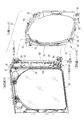
図2に示すように、本体部材11の前面上部には、分離ユニット12が取り付けられる。この本体部材11の左側端部には、軸受け部20と、軸受け片21とが設けられている。軸受け部20は、ベース部材40の上端に設けられた回動軸47を受け入れ、受け入れた回動軸47を保持する。軸受け片21は挿通孔22(図4参照)を備えており、この挿通孔22にベース部材40の下端に設けられた回動軸49が挿通される。これにより、ベース部材40が本体部材11の左側端部に軸着される。
As shown in FIG. 2, a
本体部材11の左側端部には、位置決め突起(位置決め部)25,26と、板バネ(押圧部材)28,29とが設けられている。位置決め突起25,26は、本体部材11の上下方向に、所定の間隔を空けた2カ所に設けられる。これら位置決め突起25,26は、遊技盤70の左側端部における前後方向の位置決めを行うために設けられている。
Positioning protrusions (positioning portions) 25 and 26 and leaf springs (pressing members) 28 and 29 are provided on the left end portion of the
板バネ28は、位置決め突起25よりも上方に設けられ、板バネ29は位置決め突起26よりも下方に設けられている。板バネ28は、遊技盤70の左側端部の上端側を本体部材11の前面に向けて押圧し、板バネ29は、遊技盤70の左側端部の下端側を本体部材11の前面に向けて押圧する。これら板バネ28,29の押圧を受けて、遊技盤70の左側端部が位置決め突起25,26に押し当てられる。
The
本体部材の左側端部で、位置決め突起の25,26の間となる箇所には、突出片(突出部)30,31が設けられている。これら突出片30,31は、分離ユニット12を本体部材11に取り付けたときに、遊技盤70の側面70aに当接されることで、本体部材11の幅方向における遊技盤70の位置決めを行う。
Protruding pieces (protruding portions) 30 and 31 are provided at positions between the positioning
本体部材11の右側端部には、その上端側と下端側に固定用レバー(固定部材)32,33が回転自在に設けられている。これら固定用レバー32,33は略菱形形状からなる頭部を備えたT字状から形成されている。分離ユニット12を本体部材11に取り付ける場合には、固定レバー32,33の頭部を、その長手方向が本体部材11の上下方向に平行となる垂直状態で保持した後、遊技盤ユニット42の遊技領域形成部材71に設けられた挿通孔87,88にそれぞれ挿通する。その後、固定用レバー32,33を、その長手方向が本体部材11の上下方向と平行となる垂直状態から、本体部材11の上下方向と直交する水平状態まで回転させることで、挿通孔87,88の周縁部に固定用レバー32,33がそれぞれ係止される。
Fixing levers (fixing members) 32 and 33 are rotatably provided at the upper end side and the lower end side of the right end portion of the
本体部材11は、その上下方向と直交する平面35を備えている。この平面(当接面)35は、分離ユニット12を本体部材11に取り付けたときに、遊技盤70の下面が当接して載置されることで、本体部材11の上下方向における遊技盤の位置決めを行う基準面となる。
The
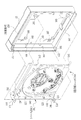
図3及び4に示すように、分離ユニット12は、ベース部材40と、前面扉41と、遊技盤ユニット42とから構成されている。ベース部材40は、上下方向を長手方向とする略L字状からなる。このベース部材40の上端部及び下端部には、ベース部材40の前方に向けて突出する支持片45,46が設けられている。支持片45には、その上面から突出する回動軸(軸着部)47と、軸受け孔(軸着部)48とが設けられている。また、支持片46には、その下面から突出する回動軸49と、上面から突出する回動軸50とが設けられている。支持片45の回動軸47と支持片46の回動軸49とは同軸となるように、それぞれ設けられている。回動軸47は、本体部材11に設けられた軸受け部20に保持され、回動軸49は本体部材11に設けられた軸受け片21の挿通孔22に挿通される。また、軸受け孔48の中心と回動軸50の中心とが同一となるように設けられている。軸受け孔48は、前面扉41の回動軸65を挿通し、回動軸50は前面扉41の下端に設けられた軸受け孔66に挿入される。
As shown in FIGS. 3 and 4, the
ベース部材40の壁面40aには、その上下方向に所定の間隔を空けて、位置規制用突起(位置規制部)55,56が設けられている。位置規制用突起55,56は、ベース部材40に遊技盤ユニット42を取り付けたときに、遊技盤ユニット42の左側端部を、ベース部材40の前後方向において一定のガタ付きが生じる範囲で規制する。
The
ベース部材40の壁面40aで、位置規制用突起55と位置規制用突起56との間には、挿通孔(第1挿通部)57,58、及び挿通孔(第2挿通部)59,60が設けられている。挿通孔57,58は、ベース部材40の壁面40aの前端側に設けられている。これら挿通孔57,58は、分離ユニット12を本体部材11に取り付けるときに、本体部材11に設けられた位置決め突起25,26がそれぞれ挿通される。また、挿通孔59,60は、ベース部材40の壁面40aの後端側に設けられている。これら挿通孔59,60は、分離ユニット12を本体部材11に取り付けるときに、本体部材11に設けられた突出片30,31がそれぞれ挿通される。
On the
ベース部材40の上端部及び下端部には、保持レバー(保持部材)61,62が設けられている。なお、この保持レバー61,62は、本体部材11の右側端部に設けられる固定用レバー32,33と同一の構成となっているので、ここでは、その詳細を省略する。この保持レバー61,62は、ベース部材40に遊技盤ユニット42を取り付けるときに、遊技盤ユニット42の遊技領域形成部材71の左側端部の上端及び下端に設けられた挿通孔85,86にそれぞれ挿通され、その挿通後の回転により挿通孔85,86の周縁部と係止される。
Holding levers (holding members) 61 and 62 are provided at the upper and lower ends of the base member 40. Since the holding levers 61 and 62 have the same configuration as the fixing levers 32 and 33 provided at the right end of the
前面扉41は、その背面から見て右側端部の上端に回動軸65を備え,また、右側端部の下端に軸受け孔66が設けられている。回動軸65は、ベース部材40の支持片45に設けられた軸受け孔48に挿通され、軸受け孔66には、支持片46に設けられた回動軸50が挿通される。この前面扉41の背面側には、前面扉41の開口41aを塞ぐガラス67が取り付けられている。
The
遊技盤ユニット42は、遊技盤70と、遊技領域形成部材71とを備えている。遊技盤70には、図示しない障害釘や風車の他に、センター役物75と呼ばれる構造物や、始動チャッカー76、通常チャッカー77、アタッカ78などの入賞装置が配設されている(図1参照)。なお、図3及び図4においては、図の煩雑さを省略するため、これら構造物や入賞装置を省略してある。
The
遊技領域形成部材71は、その中央が開口された枠形状からなり、遊技盤70の前面に配置される。この遊技領域形成部材71が遊技盤70の前面に配置されることで遊技領域80が形成される他、遊技領域80の左方に沿ってパチンコ球が遊技領域80に向けて案内される案内通路81が形成される。この案内通路81の下端部は、分離ユニット12を本体部材11に取り付けたときに、本体部材11に設けられた送出通路18と連通する。
The game
この遊技領域形成部材71の四隅には、その上下方向が長手方向となる略菱形の挿通孔85,86,87,88が設けられている。これら挿通孔85,86,87,88のうち、遊技領域形成部材71の左側端部に設けられる挿通孔85,86には、ベース部材40に設けられた保持レバー61,62がそれぞれ挿通される。一方、遊技領域形成部材71の右側端部に設けられる挿通孔87,88には、本体部材11に設けられる固定用レバー32,33がそれぞれ挿通される。また、挿通孔85の近傍には、挿通孔85及び挿通孔85の周縁部に係止された保持レバー61を被覆するためのカバー91が設けられる。同様にして、挿通孔86、88の近傍にもこれら挿通孔や、挿通孔の周縁部に係止された固定用レバー61,62をそれぞれ被覆するカバー92,93が設けられている。
At the four corners of the game
このような分離ユニット12は、以下のようにして組み立てられる。図5に示すように、前面扉41の左端部をベース部材40に軸着した後、遊技盤ユニット42の左側端部をベース部材40に向けて(C方向に)移動させて、その左側端部を、位置規制用突起55とベース部材40の壁面40bとの間に差し込む。その後、位置規制用突起55とベース部材40の壁面40bとの間に差し込まれた遊技盤ユニット42の左側端部を中心にしてD方向に回動させ、垂直状態に回転させた保持レバー61を遊技領域形成部材71に設けられた挿通孔85に挿通させる。同様にして、保持レバー62を遊技領域形成部材71に設けられた挿通孔86に挿通させる。
Such a
これら挿通の後、保持レバー61を水平状態となるように回転操作し、保持レバー61と挿通孔85の周縁部とを係止させる。また、保持レバー62を回転操作して、保持レバー62と挿通孔86の周縁部とを係止させる。これにより、ベース部材40に遊技盤ユニット42が仮保持された状態で分離ユニット12が完成する。分離ユニット12が完成したときには、遊技盤70の前面左側端部と位置規制用突起55,56との間には隙間が生じており、また、遊技盤ユニット42は、その左側端部のみがベース部材40に保持されていることから、遊技盤ユニット42はベース部材40の前後方向にガタつきが生じている。このような状態で、分離ユニット12を本体部材11に取り付ける。
After these insertions, the holding
図6に示すように、分離ユニット12を本体部材11に取り付けるときには、ベース部材40の支持片46に設けられた回動軸49を本体部材11の軸受け片21の挿通孔22に挿通した後、ベース部材40の支持片45に設けられた回動軸47を本体部材11の軸受け部20にて保持する。これにより、分離ユニット12が本体部材11に軸着される。
As shown in FIG. 6, when attaching the
図7及び図8に示すように、分離ユニット12が本体部材11に軸着された後、遊技盤ユニット42の右側端部を本体部材11に向けて(E方向に)回動させると、遊技盤ユニット42の左側端部を保持するベース部材40もE方向に回動する。この回動時に、ベース部材40に設けられた挿通孔57,58に本体部材11に設けられた位置決め突起25,26がそれぞれ挿通され、また、ベース部材40の挿通孔59,60に本体部材11に設けられた突出片30,31がそれぞれ挿通される。
As shown in FIGS. 7 and 8, after the
また、遊技領域形成部材71の右側端部に設けられた挿通孔87,88に、本体部材11の右側端部に設けられ、垂直状態に保持された固定用レバー32,33がそれぞれ挿通される。さらに、遊技盤ユニットの右側端部をE方向に回動させる過程で、遊技盤70の下面が本体部材11の基準面35に当接した載置状態となる。
Further, the fixing levers 32 and 33 provided at the right end portion of the
遊技盤ユニット42が本体部材11に当接されることで、遊技盤ユニット42の回動が停止される。そして、固定用レバー32を水平状態となるように回転操作し、固定用レバー32を挿通孔87の周縁部に係止する。同様にして、固定用レバー33を回転操作し、固定用レバー33を挿通孔88の周縁部に係止する。これにより、遊技盤ユニット42を保持したベース部材40が本体部材に収納される。
When the
なお、遊技盤ユニット42及びベース部材40の回動の際に、本体部材11に設けられた板バネ28,29が遊技盤70の左側端部の背面に当接され、板バネ28,29を押し込む。遊技盤70に押圧されることで、板バネ28,29には復帰力が働き、遊技盤70を本体部材11の前面に向けて(F方向に)押圧する。この押圧を受けて、遊技盤70の左側端部が押し出され、位置決め突起25,26に当接される。これにより、本体部材の前後方向に対する遊技盤70の左側端部の位置決めが行われる。
When the
また、遊技盤ユニット42の右側端部は、固定用レバー32,33の回転操作時に、遊技盤ユニット42の左側端部がベース部材40に向けて移動し、遊技盤70の側面70aがベース部材40の挿通孔59,60に挿通された突出片30,31にそれぞれ押し付けられる。これにより、本体部材11の幅方向における遊技盤ユニット42の位置決めが行われる。また、本体部材11に取り付けられた遊技盤ユニット42は、遊技盤70の下面が基準面35に当接して載置されることで、本体部材11の上下方向における遊技盤ユニット42の位置決めが行われる。これら位置決めによって、固定用レバー32,33の回転操作後の遊技盤70の捩れを防止することができる。これにより、遊技盤ユニット42に設けられる案内通路81の下端部と、本体部材11に設けられる送出通路18との連通状態が良好な状態で保持されるので、安定したパチンコ球の打ち出しを行うことができる。
Further, the right end portion of the
本実施形態では、遊技盤ユニットの左側端部の位置をベース部材に設けられた位置規制突起によって規制した状態で、保持レバーと保持レバーが挿通される挿通孔の周縁部とを係止させる形態としているが、この他に、遊技盤ユニットをベース部材に軸着した後に、保持レバーと保持レバーが挿通される挿通孔の周縁部とを係止させることも可能である。 In the present embodiment, the holding lever and the peripheral portion of the insertion hole through which the holding lever is inserted are locked in a state where the position of the left end portion of the game board unit is regulated by the position regulating projection provided on the base member. However, it is also possible to lock the holding lever and the peripheral portion of the insertion hole through which the holding lever is inserted after the game board unit is pivotally attached to the base member.
図9に示すように、分離ユニット100は、本実施形態と同様に、ベース部材101、前面扉102、遊技盤ユニット103から構成される。ベース部材101は、その上下方向が長手方向となるように形成され、その上端部と下端部とに前面に向けて突出する支持片105,106が設けられている。
As shown in FIG. 9, the separation unit 100 includes a
支持片105には、上面から上方に突出する回動軸(第2の軸着部)110と、軸受け孔111,112とが設けられている。また、支持片106には、支持片105の回動軸110と同軸となる軸受け孔(第2の軸着部)115と、支持片105の軸受け孔111と同軸となる回動軸116と、軸受け孔112と中心軸が同一となる軸受け孔117とが設けられている。このベース部材101の上端部及び下端部には、保持レバー(保持部材)120,121がそれぞれ設けられ、これら保持レバー120,121との間には、挿通孔(第1挿通部)122,123及び挿通孔(第2挿通部)124,125が設けられている。
The
前面扉102は、背面から見て右側端部の上端に、支持片105の軸受け孔111に挿通される回動軸130を備え、また、右側下端に支持片106に設けられた回動軸116が挿通される軸受け孔131を備えている。
The front door 102 includes a
遊技盤ユニット103は、その左側端部の上端及び下端に回動軸(第1の軸着部)141,142が設けられている。また、遊技盤ユニット103の四隅に挿通孔143,144,145,146が設けられている。なお、符号147は遊技領域、符号148は打ち出されたパチンコ球を遊技領域147に向けて案内する案内通路を示す。
The game board unit 103 is provided with rotating shafts (first shaft mounting portions) 141 and 142 at the upper and lower ends of the left end thereof. In addition, insertion holes 143, 144, 145, 146 are provided at the four corners of the game board unit 103.
分離ユニット100の組み立て時には、ベース部材101の支持片105に設けられた軸受け孔112に回動軸141を、支持片106の軸受け孔117に回動軸142をそれぞれ挿通させることで、遊技盤ユニット103をベース部材101に軸着する。この軸着の後、遊技盤ユニット103を回動させ、遊技盤ユニット103に設けられた挿通孔143,144に、ベース部材101に設けられた保持レバー120,121をそれぞれ挿通させる。その後、保持レバー120,121を回転操作して、保持レバー120,121を挿通孔143,144の周縁部に係止させる。これにより、遊技盤ユニット103の左側端部がベース部材101に取り付けられる。なお、前面扉102は、遊技盤ユニット103をベース部材101に取り付ける前にベース部材101に軸着してもよいし、遊技盤ユニット103をベース部材101に取り付けた後にベース部材101に軸着してもよい。
At the time of assembling the separation unit 100, the
図10に示すように、組み立てられた分離ユニット100を本体部材150に取り付ける際には、ベース部材101の支持片106に設けられた軸受け孔115に、本体部材150の左側端部の支持片151に設けられた回動軸152を挿通させた後、支持片105に設けられた回動軸110を、本体部材150に設けられた軸受け部154に保持させる。これにより、分離ユニット100が本体部材150に軸着される。
As shown in FIG. 10, when the assembled separation unit 100 is attached to the
この軸着の後、ベース部材101及び遊技盤ユニット103を本体部材150に向けて回動させると、ベース部材101に設けられた挿通孔122,123に、本体部材150に設けられた位置決め突起(位置決め部)160,161が挿通され、また、ベース部材101に設けられた挿通孔124,125に、本体部材150に設けられた突出片(突出部)162,163が挿通される。また、遊技盤ユニット103の右側端部の上端及び下端に設けられた挿通孔145,146に、本体部材150に設けられた固定用レバー(固定部材)164,165が挿通される。このとき、遊技盤ユニット103の下面が本体部材150の当接面168に当接される。
When the
この過程で、本体部材150に設けられた板バネ(押圧部材)166,167が遊技盤ユニット103の背面に当接され、遊技盤ユニット103の左側端部を前面に向けて押圧する。これにより、遊技盤ユニット103の前面左側端部が、位置決め突起160,161に押し当てられる。最後に固定用レバー164,165を回転操作して、固定用レバー164,165を挿通孔145,146の周縁部に係止させる。この固定用レバー164,165の回転操作時に、遊技盤ユニット103が本体部材150の左側端部に向けて移動し、ベース部材101の挿通孔124,125から突出する本体部材150の突出片162,163にそれぞれ押し当てられる。これにより、本体部材150の幅方向における遊技盤ユニット103の位置決めが行われる。
In this process, leaf springs (pressing members) 166 and 167 provided on the
つまり、ベース部材101に遊技盤ユニット103を軸着したときに、遊技盤ユニット103の回動軸141,142の位置精度や部品精度、ベース部材101の挿通孔112,117の位置精度や部品精度が低い場合や、遊技盤ユニット103とベース部材101との取り付け精度が低い場合であっても、遊技盤ユニット103が本体部材150に対して正確に位置決めされる。なお、図示は省略するが、本体部材150には、発射装置や、発射装置によって打ち出されるパチンコ球を送り出す送出通路が設けられているので、遊技盤ユニット103を本体部材150に軸着した場合であっても、案内通路と送出通路との連通状態は良好となることは言うまでもない。
That is, when the game board unit 103 is pivotally attached to the
本実施形態では、遊技盤ユニットは、その左側端部をベース部材に保持される形態としているが、これに限定する必要はなく、遊技盤ユニットの四隅をベース部材に保持する形態であってもよい。 In the present embodiment, the game board unit is configured such that the left end portion thereof is held by the base member. However, the present invention is not limited to this, and the game board unit may be configured such that the four corners of the game board unit are held by the base member. Good.
本実施形態では、位置決め用突起をベース部材に設けられた挿通孔に挿通させる形態としているが、挿通孔の代わりに、位置決め用突起の幅よりも大きい幅からなる切り欠き部を設け、この切り欠き部に位置決め用突起を挿通させるようにしても良い。 In the present embodiment, the positioning protrusion is inserted into the insertion hole provided in the base member, but instead of the insertion hole, a notch portion having a width larger than the width of the positioning protrusion is provided. The positioning projection may be inserted into the notch.
10 パチンコ機(遊技機)
11,150 本体部材(遊技機本体)
12,100 分離ユニット
17 発射装置
18 送出通路
20 軸受け部
21 軸受け片
22 挿通孔
25,26,160,161 位置決め突起(位置決め部)
28,29,166,167 板バネ(押圧部材)
30,31,162,163 突出片(突出部)
32,33,164,165 固定用レバー(固定部材)
40,101 ベース部材
41,102 前面扉
42,103 遊技盤ユニット
47,49 回動軸(軸着部)
55,56 位置規制用突起(位置規制部)
57,58,122,123 挿通孔(第1挿通部)
59,60,124,125 挿通孔(第2挿通部)
61,62,120,121 保持レバー(保持部材)
70 遊技盤
71 遊技領域形成部材
80 遊技領域
81 案内通路
85〜88 挿通孔
110 回動軸(第2の軸着部)
115 軸受け孔(第2の軸着部)
140,141 回動軸(第1の軸着部)
10 Pachinko machines (game machines)
11,150 body member (game machine body)
12,100
28, 29, 166, 167 Leaf spring (pressing member)
30, 31, 162, 163 Protruding piece (protruding part)
32, 33, 164, 165 Fixing lever (fixing member)
40, 101
55, 56 Position restriction projection (position restriction part)
57, 58, 122, 123 Insertion hole (first insertion part)
59, 60, 124, 125 Insertion hole (second insertion part)
61, 62, 120, 121 Holding lever (holding member)
70
115 Bearing hole (second bearing part)
140, 141 Rotating shaft (first shaft mounting portion)
Claims (7)
前記ベース部材に設けられ、前記遊技盤の幅方向の一端部を仮保持する保持部材と、
前記ベース部材に仮保持される前記遊技盤の一端部を、前記ベース部材の前後方向に一定の範囲内で規制する位置規制部と、
前記遊技盤が仮保持された前記ベース部材を前記遊技機本体に収納する位置と前記遊技機本体から突出する位置との間で回動可能となるように前記ベース部材を前記遊技機本体に軸着する軸着部と、
前記遊技盤が仮保持された前記ベース部材を前記遊技機本体に収納したときに、前記遊技盤の幅方向の一端部を前記遊技機本体から前方に向けて押圧する押圧部材と、
前記遊技機本体に設けられ、前記押圧部材によって押圧される前記遊技盤の幅方向の一端部が押し当てられる位置決め部と、を備えたことを特徴とする遊技機。 In a gaming machine comprising a gaming board having a gaming area where a pachinko ball flows down, a base member to which the gaming board is attached, and a gaming machine main body that houses the base member to which the gaming board is attached.
A holding member provided on the base member and temporarily holding one end of the game board in the width direction;
A position restricting portion for restricting one end portion of the game board temporarily held by the base member within a certain range in the front-rear direction of the base member;
The base member is pivoted to the gaming machine main body so as to be rotatable between a position where the base board temporarily held by the gaming board is stored in the gaming machine main body and a position protruding from the gaming machine main body. A shaft attachment part to be worn,
A pressing member that presses one end in the width direction of the gaming board forward from the gaming machine body when the base member on which the gaming board is temporarily held is stored in the gaming machine body;
A gaming machine comprising: a positioning portion provided in the gaming machine main body and pressed against one end portion in the width direction of the gaming board pressed by the pressing member.
前記遊技盤の幅方向の一端部を前記ベース部材に軸着する第1の軸着部と、
前記ベース部材に軸着された前記遊技盤を、前記第1の軸着部の近傍で仮保持する保持部材と、
前記遊技盤が仮保持された前記ベース部材を前記遊技機本体に収納する位置と前記遊技機本体から突出する位置との間で回動可能となるように前記ベース部材を前記遊技機本体に軸着する第2の軸着部と、
前記遊技盤が仮保持された前記ベース部材が前記遊技機本体に収納されたときに、前記遊技盤の幅方向の一端部を前記遊技機本体から前方に向けて押圧する押圧部材と、
前記遊技機本体に設けられ、前記押圧部材によって押圧される前記遊技盤の幅方向の一端部が押し当てられる位置決め部と、を備えたことを特徴とする遊技機。 In a gaming machine comprising a gaming board having a gaming area where a pachinko ball flows down, a base member to which the gaming board is attached, and a gaming machine main body that houses the base member to which the gaming board is attached.
A first pivoting portion that pivotally attaches one end portion in the width direction of the game board to the base member;
A holding member that temporarily holds the game board pivotally attached to the base member in the vicinity of the first pivotally attached portion;
The base member is pivoted to the gaming machine main body so as to be rotatable between a position where the base board temporarily held by the gaming board is stored in the gaming machine main body and a position protruding from the gaming machine main body. A second shaft attachment portion to be worn;
A pressing member that presses one end in the width direction of the gaming board forward from the gaming machine body when the base member on which the gaming board is temporarily held is stored in the gaming machine body;
A gaming machine comprising: a positioning portion provided in the gaming machine main body and pressed against one end portion in the width direction of the gaming board pressed by the pressing member.
前記ベース部材に設けられ、前記突出部を挿通させる第2挿通部と、を備えていることを特徴とする請求項1〜3いずれか1つ記載の遊技機。 A protrusion provided on the gaming machine main body, protruding from a surface facing the base member housed in the gaming machine main body, and abutting against a side surface facing the base member of the side surface of the gaming board;
The gaming machine according to claim 1, further comprising: a second insertion portion that is provided on the base member and allows the protrusion to be inserted therethrough.
前記遊技盤は、前記発射装置によって打ち出されたパチンコ球を遊技領域の外周に沿って案内し、その下端側が前記送出通路と連通される案内通路を備えていることを特徴とする請求項1〜5いずれか1つ記載の遊技機。 The gaming machine main body includes a launching device that launches a pachinko ball and a delivery passage that delivers the pachinko ball launched by the launching device on one end side where the holding member is held,
The game board includes a guide passage that guides a pachinko ball launched by the launching device along an outer periphery of a game area, and a lower end side of the game board communicates with the delivery passage. 5. A gaming machine according to any one of the five.
Priority Applications (1)
| Application Number | Priority Date | Filing Date | Title |
|---|---|---|---|
| JP2007019602A JP4699397B2 (en) | 2007-01-30 | 2007-01-30 | Game machine |
Applications Claiming Priority (1)
| Application Number | Priority Date | Filing Date | Title |
|---|---|---|---|
| JP2007019602A JP4699397B2 (en) | 2007-01-30 | 2007-01-30 | Game machine |
Publications (2)
| Publication Number | Publication Date |
|---|---|
| JP2008183225A JP2008183225A (en) | 2008-08-14 |
| JP4699397B2 true JP4699397B2 (en) | 2011-06-08 |
Family
ID=39726651
Family Applications (1)
| Application Number | Title | Priority Date | Filing Date |
|---|---|---|---|
| JP2007019602A Expired - Fee Related JP4699397B2 (en) | 2007-01-30 | 2007-01-30 | Game machine |
Country Status (1)
| Country | Link |
|---|---|
| JP (1) | JP4699397B2 (en) |
Families Citing this family (4)
| Publication number | Priority date | Publication date | Assignee | Title |
|---|---|---|---|---|
| JP5402170B2 (en) * | 2009-04-03 | 2014-01-29 | 株式会社三洋物産 | Game machine |
| JP5776747B2 (en) * | 2013-10-31 | 2015-09-09 | 株式会社三洋物産 | Game machine |
| JP2014131593A (en) * | 2013-10-31 | 2014-07-17 | Sanyo Product Co Ltd | Game machine |
| JP5943034B2 (en) * | 2014-05-22 | 2016-06-29 | 株式会社三洋物産 | Game machine |
Family Cites Families (5)
| Publication number | Priority date | Publication date | Assignee | Title |
|---|---|---|---|---|
| JPH0336379Y2 (en) * | 1985-12-11 | 1991-08-01 | ||
| JP3889965B2 (en) * | 2001-12-27 | 2007-03-07 | 株式会社オリンピア | Bullet ball machine |
| JP4338431B2 (en) * | 2003-04-24 | 2009-10-07 | 株式会社Mrd | Game board mounting structure |
| JP4404614B2 (en) * | 2003-12-09 | 2010-01-27 | 京楽産業.株式会社 | Bullet ball machine |
| JP4188266B2 (en) * | 2004-03-03 | 2008-11-26 | 株式会社オリンピア | Bullet ball machine |
-
2007
- 2007-01-30 JP JP2007019602A patent/JP4699397B2/en not_active Expired - Fee Related
Also Published As
| Publication number | Publication date |
|---|---|
| JP2008183225A (en) | 2008-08-14 |
Similar Documents
| Publication | Publication Date | Title |
|---|---|---|
| JP4699397B2 (en) | Game machine | |
| JP4785758B2 (en) | Movable winning device and game machine using the same | |
| JP3971904B2 (en) | Bullet ball machine | |
| JP4246077B2 (en) | Bullet ball machine | |
| JP2008168000A (en) | Game machine | |
| JP2004167012A (en) | Game machine | |
| JP2008183224A (en) | Separation unit for game machine | |
| JP4814144B2 (en) | Amusement stand | |
| JP4589244B2 (en) | Bullet ball machine | |
| JP4633652B2 (en) | Board case and gaming machine including the board case | |
| JP4506942B2 (en) | Ball dispenser for gaming machines | |
| JP4604054B2 (en) | Game machine | |
| JP5424501B2 (en) | Game machine | |
| JP4744579B2 (en) | Connector unit and gaming machine | |
| JP4497277B2 (en) | Ball delivery control mechanism for ball game machines | |
| JP4973909B2 (en) | Pachinko machine | |
| JP6889927B2 (en) | Pachinko machine | |
| JP4500866B2 (en) | Bullet ball machine | |
| JP4589359B2 (en) | Bullet ball machine | |
| JP6889928B2 (en) | Pachinko machine | |
| JP4417309B2 (en) | Game machine | |
| JP4024743B2 (en) | Ball delivery control mechanism for ball game machines | |
| JP4027301B2 (en) | Ball delivery control mechanism for ball game machines | |
| JP2005058427A (en) | Pinball machine | |
| JP4503054B2 (en) | Game machine |
Legal Events
| Date | Code | Title | Description |
|---|---|---|---|
| A621 | Written request for application examination |
Free format text: JAPANESE INTERMEDIATE CODE: A621 Effective date: 20080728 |
|
| A131 | Notification of reasons for refusal |
Free format text: JAPANESE INTERMEDIATE CODE: A131 Effective date: 20100825 |
|
| A977 | Report on retrieval |
Free format text: JAPANESE INTERMEDIATE CODE: A971007 Effective date: 20100825 |
|
| A521 | Request for written amendment filed |
Free format text: JAPANESE INTERMEDIATE CODE: A523 Effective date: 20101006 |
|
| TRDD | Decision of grant or rejection written | ||
| A01 | Written decision to grant a patent or to grant a registration (utility model) |
Free format text: JAPANESE INTERMEDIATE CODE: A01 Effective date: 20110202 |
|
| A61 | First payment of annual fees (during grant procedure) |
Free format text: JAPANESE INTERMEDIATE CODE: A61 Effective date: 20110302 |
|
| R150 | Certificate of patent or registration of utility model |
Ref document number: 4699397 Country of ref document: JP Free format text: JAPANESE INTERMEDIATE CODE: R150 |
|
| R250 | Receipt of annual fees |
Free format text: JAPANESE INTERMEDIATE CODE: R250 |
|
| S531 | Written request for registration of change of domicile |
Free format text: JAPANESE INTERMEDIATE CODE: R313531 |
|
| R350 | Written notification of registration of transfer |
Free format text: JAPANESE INTERMEDIATE CODE: R350 |
|
| R250 | Receipt of annual fees |
Free format text: JAPANESE INTERMEDIATE CODE: R250 |
|
| R250 | Receipt of annual fees |
Free format text: JAPANESE INTERMEDIATE CODE: R250 |
|
| R250 | Receipt of annual fees |
Free format text: JAPANESE INTERMEDIATE CODE: R250 |
|
| R250 | Receipt of annual fees |
Free format text: JAPANESE INTERMEDIATE CODE: R250 |
|
| R250 | Receipt of annual fees |
Free format text: JAPANESE INTERMEDIATE CODE: R250 |
|
| LAPS | Cancellation because of no payment of annual fees |