JP4698558B2 - Air conditioner - Google Patents
Air conditioner Download PDFInfo
- Publication number
- JP4698558B2 JP4698558B2 JP2006316711A JP2006316711A JP4698558B2 JP 4698558 B2 JP4698558 B2 JP 4698558B2 JP 2006316711 A JP2006316711 A JP 2006316711A JP 2006316711 A JP2006316711 A JP 2006316711A JP 4698558 B2 JP4698558 B2 JP 4698558B2
- Authority
- JP
- Japan
- Prior art keywords
- humidity
- indoor
- control unit
- compressor
- maximum
- Prior art date
- Legal status (The legal status is an assumption and is not a legal conclusion. Google has not performed a legal analysis and makes no representation as to the accuracy of the status listed.)
- Active
Links
- 238000001816 cooling Methods 0.000 claims description 31
- 239000003507 refrigerant Substances 0.000 claims description 10
- 238000004140 cleaning Methods 0.000 description 18
- 230000005494 condensation Effects 0.000 description 12
- 238000009833 condensation Methods 0.000 description 12
- 238000010586 diagram Methods 0.000 description 5
- 239000000428 dust Substances 0.000 description 5
- 230000007423 decrease Effects 0.000 description 3
- 238000011156 evaluation Methods 0.000 description 3
- 230000006837 decompression Effects 0.000 description 2
- 238000010438 heat treatment Methods 0.000 description 2
- 238000007664 blowing Methods 0.000 description 1
- 230000006866 deterioration Effects 0.000 description 1
- 230000000694 effects Effects 0.000 description 1
- 230000002265 prevention Effects 0.000 description 1
- 230000001681 protective effect Effects 0.000 description 1
- 238000005057 refrigeration Methods 0.000 description 1
- 230000001105 regulatory effect Effects 0.000 description 1
- 239000007787 solid Substances 0.000 description 1
- XLYOFNOQVPJJNP-UHFFFAOYSA-N water Substances O XLYOFNOQVPJJNP-UHFFFAOYSA-N 0.000 description 1
Images


Landscapes
- Air Filters, Heat-Exchange Apparatuses, And Housings Of Air-Conditioning Units (AREA)
- Air Conditioning Control Device (AREA)
Description
この発明は、空気調和機に関し、特に冷房運転を行う空気調和機に関するものである。 The present invention relates to an air conditioner, and more particularly to an air conditioner that performs a cooling operation.
従来の空気調和機における露付き防止制御は、室内湿度、又は室内エンタルピに対して圧縮機の最高回転数を常に結露を生じないようなステップ状の限界曲線より低く設定するものが開示されている(例えば、特許文献1参照)。 In conventional air conditioners, dew prevention control is disclosed in which the maximum number of rotations of the compressor is set lower than the step-shaped limit curve that does not always cause condensation with respect to room humidity or room enthalpy. (For example, refer to Patent Document 1).
従来の空気調和機における露付き制御は、運転開始時から湿度に応じて圧縮機の最高回転数を低く設定する場合があり、運転開始時の冷房快適性に関しては考えられてはいなかった。 In the conventional dew control in an air conditioner, the maximum number of revolutions of the compressor may be set low depending on the humidity from the start of operation, and cooling comfort at the start of operation has not been considered.
この発明は、上記のような課題を解決するためになされたもので、第1の目的は運転開始時の冷房快適性を損なうことがない空気調和機を得るものである。 The present invention has been made to solve the above-described problems, and a first object thereof is to obtain an air conditioner that does not impair the cooling comfort at the start of operation.
また、第2の目的は空気調和機の室内機に露が付くことを防止することができる空気調和機を得るものである。 Moreover, the 2nd objective is to obtain the air conditioner which can prevent that dew adheres to the indoor unit of an air conditioner.
この発明に係る空気調和機は、少なくとも、回転数可変な圧縮機、四方切替弁、室外熱交換器、冷媒減圧装置、室内熱交換器を冷媒配管で順次接続した冷媒回路と、インバータを介して圧縮機の回転数を制御する室外制御部を有する室外機と、室内の湿度を検出する室内湿度センサと、複数に区分された湿度帯が設定され、前記室内湿度センサからの室内湿度に基づいて、前記複数に区分された湿度帯の内のいずれの湿度帯かを判定して湿度帯情報として前記室外制御部に送る室内制御部を有する室内機と、を備え、室外制御部が前記室内制御部から送られる前記湿度帯情報に応じて前記圧縮機の最大回転数の設定値を変化させ、室内制御部は、冷房運転開始から所定時間経過後、所定の時間が経過する毎に前記湿度帯の区分を細分化することで前記湿度帯の数を増加させるものである。 An air conditioner according to the present invention includes at least a compressor, a four-way switching valve, an outdoor heat exchanger, a refrigerant decompression device, a refrigerant circuit in which indoor heat exchangers are sequentially connected by refrigerant piping, and an inverter. An outdoor unit having an outdoor control unit that controls the rotation speed of the compressor, an indoor humidity sensor that detects indoor humidity, and a plurality of humidity bands are set , based on the indoor humidity from the indoor humidity sensor , and a indoor unit including an indoor control unit to send to the outdoor control unit as humidity zone information to determine either whether the humidity range of the humidity range that is divided into a plurality, outdoor control unit is pre-Symbol The set value of the maximum number of rotations of the compressor is changed according to the humidity band information sent from the indoor control unit , and the indoor control unit is configured so that the predetermined time elapses after the elapse of a predetermined time from the start of the cooling operation. Subdivide humidity zones In a shall increase the number of the humidity zones.
本発明によれば、冷房を開始して所定時間経過後に、室内制御部から送られる湿度帯情報に応じて圧縮機の最大回転数の設定値を変化させることで、室内機に露が付くことを防止することが可能な空気調和機を得ることができる。 According to the present invention, the start of the cooling after the elapse of a predetermined time, by changing the maximum rotational speed of the set value of the compressor in accordance with the humidity zone information sent from the indoor control unit, rather with dew in the indoor unit it is possible to obtain an air conditioner which can prevent.
実施の形態1.
冷房運転時、吹出し温度が低いときに、室内機に露が付きそのまま時間が経過すると滴下する恐れがある。室内機に付着した露は時間経過とともに成長し、その量も多くなってくるが、露が付き始めてから成長するのにはかなりの時間を要することが多い。そのため、冷房開始後一定時間までは冷房快適性を優先し、圧縮機の周波数を高めに設定しても露付の影響は少なくてすむ。しかしながら、長時間、露が付いた状態にしておくと、成長しやがて滴下する。そのため圧縮機の最高回転数を規制する必要が出てくる。図7に室内湿度と露点温度の関係を示す。例えば室内の温度が27℃とすると、室内の相対湿度が80%のときは、その空気は23.5℃以下に低下すると結露する。また、室内温度が27℃で室内の相対湿度が40%のときには、12.7℃以下に低下すると結露する。このように、湿度が低い方が結露しにくい。
そこで、冷房開始後所定時間までは冷房快適性を優先して圧縮機の周波数を高めに設定し、所定時間が経過したら、湿度が低いときには圧縮機の最大周波数を高めに設定し、湿度が高いときには圧縮機の最大周波数を低めに設定することで、冷房開始後一定時間までの冷房快適性を損なわず、露付きを防止することが可能となる。
図1はこの発明の実施の形態1におけるヒートポンプ式空気調和機の構成図を示すものである。空気調和機20は、圧縮機1、四方切替弁2、室外熱交換器3、冷媒減圧装置4、室内熱交換器5を冷媒配管で順次接続し、室外熱交換器の送風機6、室内熱交換器の送風機7を備え、冷凍サイクルを構成している。又室内の温度を検出する室内温度センサ8、室内の相対湿度を検出する室内湿度センサ9を備える。また室内熱交換器5へ空気中の埃を進入させないためのフィルタ10、フィルタを定期的に自動で掃除することが出来る自動フィルタお掃除機構11を備える。四方切替弁2は冷房運転、暖房運転に切替えることができ、実線矢印方向に切替えることによって暖房サイクルを形成し、破線矢印方向に切替えることによって冷房サイクルを形成している。
During cooling operation, when the blow-out temperature is low, there is a risk that the indoor unit will be dewed and dripping if time passes. The dew adhering to the indoor unit grows with the passage of time, and the amount of the dew grows. However, it often takes a considerable amount of time to grow after the dew begins to attach. Therefore, priority is given to cooling comfort until a certain time after the start of cooling, and even if the frequency of the compressor is set higher, the influence of the exposure is small. However, if the dew is left for a long time, it grows and then drops. Therefore, it is necessary to regulate the maximum rotation speed of the compressor. FIG. 7 shows the relationship between room humidity and dew point temperature. For example, if the indoor temperature is 27 ° C., and the indoor relative humidity is 80%, the air will condense when it falls below 23.5 ° C. Further, when the indoor temperature is 27 ° C. and the indoor relative humidity is 40%, condensation occurs when the temperature falls to 12.7 ° C. or lower. In this way, condensation is less likely at lower humidity.
Therefore, the compressor frequency is set higher for a predetermined time after the start of cooling, and the compressor frequency is set higher, and when the humidity is low, the maximum frequency of the compressor is set higher when the humidity is low. Occasionally, by setting the maximum frequency of the compressor to be low, it is possible to prevent dew condensation without impairing the cooling comfort until a certain time after the start of cooling.
FIG. 1 shows a configuration diagram of a heat pump type air conditioner according to
また、図2は、図1に示した空気調和機の制御系を表すブロック図である。
図2に示すように、空気調和機20は、室内機に搭載されたマイコンによって構成される室内制御部12と、室外機に搭載されたマイコンによって構成される室外制御部13とを備えている。室内制御部12と室外制御部13は接続線14にて接続されており、互いにデータおよび制御信号のやり取りをする。室内送風機7は回転数制御回路15を介して室内制御部12によってコントロールされる。室外送付機8は回転数制御回路16を介して室外制御部13によってコントロールされている。四方切替弁2、冷媒減圧装置4は室外制御部13によってコントロールされる。
室内制御部12は室内温度センサ8から入力された信号から室内温度を算出するとともに、利用者がリモコンを用いて所望の設定を行うことでリモコン18より送られてきた設定温度データと上記室内温度との温度差を算出し、室外制御部13へデータを送る。室外制御部13は室内12から送られてきた上記温度差のデータから圧縮機運転回転数を決定し、インバータ回路17を介して圧縮機1の回転数をコントロールする。
また、室内制御部12は室内湿度センサ9から入力された信号から室内湿度を算出する。また、室内制御部12は、リモコン18によって運転を開始された時から内蔵タイマーを起動して経過時間をカウントさせる。しかして、室内制御部12は、上記室内湿度の値及び、上記タイマーでカウントされた経過時間に基づいて高湿度帯、中湿度帯、低湿度帯のいずれかを判定し、湿度帯情報として室外制御部13へデータを送る。
室外制御部13は室内制御部12から送られてきた上記湿度帯を基に圧縮機最高回転数を判定する。室外制御部13は、さらに上記圧縮機運転回転数が上記圧縮機最高回転数を超えている場合には、圧縮機運転回転数を圧縮機最高回転数を超えない値に修正し、インバータ回路17を介して圧縮機1の回転数をコントロールする。これにより常に正確な圧縮機最高回転数を確保することが可能になる。
FIG. 2 is a block diagram showing a control system of the air conditioner shown in FIG.
As shown in FIG. 2, the air conditioner 20 includes an
The
The
The
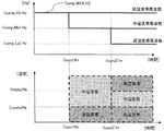
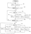
図3は圧縮機の最大回転数の設定値を示す図である。図4は室外制御部13による圧縮機の最大回転数設定のフローチャートを示す。この例では、圧縮機の最大回転数を最大値(comp_Hi)Hz、中間値(comp_Me)Hz、最小値(comp_Lo)Hzの3つに設定する場合について説明する。
室外制御部13は、冷房運転開始後、(tuyu1)時間までは、相対湿度の値に関係なく、圧縮機の最大回転数を最大値(comp_Hi)Hzに設定する(ステップS41、S42)。これにより、圧縮機1は最大能力で運転するので、冷房開始後一定時間までの冷房快適性を損なわず、露付きを防止することが可能となる。上記(tuyu1)時間は、平均的な住宅で設定温度に室温が到達する時間を設定する。平均的な住宅においては、約1時間程度で設定温度に室温を到達させることが可能なため1時間程度に設定するのがよい。しかし、露が滴下する恐れのある場合は短めに設定してもよい。
また、室外制御部13は、冷房運転開始後(tuyu1)時間以上で(tuyu2)時間未満の間は、相対湿度が、(Lositu)%未満の場合には低湿度帯の圧縮機最大回転数を最大値(comp_Hi)Hzに設定し(ステップS43、S45、S46)、相対湿度が(Lositu)%以上の場合には中湿度帯の圧縮機最大回転数を中間値(comp_Me)Hzに設定する(ステップS43、S44、S46)。
また、室外制御部13は、冷房運転開始後(tuyu2)時間以上経過したら、相対湿度が(Lositu)%未満の場合には低湿度帯の圧縮機最大回転数を最大値(comp_Hi)Hzに設定し(ステップS47、S50)、相対湿度が(Lositu)%以上で(Hisitu)%未満の場合には、中湿度帯の圧縮機最大回転数を中間値(comp_Me)Hzに設定し(ステップS47、S49)、相対湿度が(Hisitu)以上の場合には、高湿度の圧縮機最大回転数を最小値(comp_Lo)Hzに設定する(ステップS47、S48)。
以上のように、湿度が高い場合でも、時間経過とともに圧縮機の最大周波数を規制していくことで、露付き防止を図りつつ、冷房快適性の悪化を防止することが可能になる。
なお、図3、図4では湿度帯を3湿度帯、時間帯を3区切りとしているが、これに限らず共に3つ以上でもよい。この場合にも同様の効果を奏する。
FIG. 3 is a diagram showing a set value of the maximum rotation speed of the compressor. FIG. 4 shows a flowchart for setting the maximum rotation speed of the compressor by the
The
In addition, the
In addition, the
As described above, even when the humidity is high, by regulating the maximum frequency of the compressor over time, it becomes possible to prevent deterioration of cooling comfort while preventing dew condensation.
3 and 4, the humidity zone is divided into three humidity zones and the time zone is divided into three. However, the present invention is not limited to this, and three or more may be used. In this case, the same effect is obtained.
なお、最大値(comp_Hi)Hzは、空気調和機に使用されている圧縮機で使用可能な最大回転数(本体制御における保護装置が作動しないで通常連続運転が可能な範囲の最大値 圧縮機の種類にもよるが、4.0kwの空気調和機において100Hz程度)を設定するのが望ましい。このようにすることで、空気調和機の持つ最大の能力を発揮することが可能であり、冷房快適性に最大限寄与することができる。
また、中間値(comp_ Me)Hzは空気調和機の適用乗数の冷房能力以上になるような回転数を設定することが望ましい。このようにすることで、冷房定格能力を発揮することができ、空気調和機の必要な冷房快適性を確保することができる。(圧縮機の種類にもよるが、4.0kwの空気調和機において70Hz程度を設定する。)
また、最小値(comp_ Lo)Hzは空気調和機の適用乗数の冷房能力の2/3以上になるような回転数を設定することが望ましい。このようにすることで、通常、空気調和機を使用する環境では、ほぼ冷房快適性を満足することが可能になる。(圧縮機の種類にもよるが、4.0kwの空気調和機において50Hz程度を設定する。)
通常、室内機への着露量は4時間程度経過すると多くなり、周辺の着露水と結合し室内機から滴下する。そのため、(tuyu2)時間は1時間程度の余裕をもって3時間程度に設定するのが望ましい。しかし、事前評価によって早めに滴下する場合には、より短めに設定するのが良い。
(Hisitu)%は、事前評価において(comp_ Lo)Hzで長時間運転しても着露が発生しないと判明した値を設定するが、通常の空気調和機で使用される環境で相対湿度が60%以下の場合にはほぼ着露は発生しないため、60%程度にする。
(Lositu)%は、事前評価において(comp_ Hi)Hzで長時間運転しても着露が発生しないと判明した値を設定する。
The maximum value (comp_Hi) Hz is the maximum number of revolutions that can be used in the compressor used in the air conditioner (the maximum value in the range where normal continuous operation is possible without the protective device in the main unit control being activated). Although it depends on the type, it is desirable to set (about 100 Hz in a 4.0 kw air conditioner). By doing in this way, it is possible to exhibit the maximum capability of the air conditioner, and to contribute to the cooling comfort to the maximum extent.
The intermediate value (comp_Me) Hz is desirably set to a rotational speed that is equal to or higher than the cooling capacity of the applicable multiplier of the air conditioner. By doing in this way, the cooling rated capacity can be exhibited, and the necessary cooling comfort of the air conditioner can be ensured. (Depending on the type of compressor, about 70 Hz is set in a 4.0 kW air conditioner.)
The minimum value (comp_Lo) Hz is desirably set to a rotational speed that is 2/3 or more of the cooling capacity of the applied multiplier of the air conditioner. By doing in this way, it becomes possible to satisfy cooling comfort substantially in the environment where an air conditioner is normally used. (Depending on the type of compressor, about 50 Hz is set in a 4.0 kw air conditioner.)
Usually, the amount of dew on the indoor unit increases after about 4 hours, and is combined with surrounding dewed water and dropped from the indoor unit. Therefore, it is desirable to set the (tuyu2) time to about 3 hours with a margin of about 1 hour. However, it is better to set a shorter value in the case of dripping earlier by prior evaluation.
(Hisitu)% is set to a value determined in the prior evaluation that no dew condensation occurs even if it is operated for a long time at (comp_Lo) Hz, but the relative humidity is 60 in an environment used in a normal air conditioner. If it is less than or equal to%, almost no condensation occurs, so it is set to about 60%.
(Lositu)% is set to a value determined in the pre-evaluation that no dew condensation occurs even if it is operated for a long time at (comp_Hi) Hz.
図5は冷房運転時の圧縮機最大回転数変化の1例を示すものである。運転開始後(tuyu1)時間までは、圧縮機の最大回転数を(comp_Hi)Hzで運転する。(tuyu1)時間が経過したところで、室内湿度がどの湿度帯にいるのか判定する。室内湿度は(Lositu)%以上で中湿度帯なため、圧縮機の最大回転数は(comp_Me)Hzに設定する。(tuyu2)時間が経過したところで、室内湿度がどの湿度帯にいるのか判定する。室内湿度が(Lositu)%以上で(Hisitu)%未満のため、圧縮機の最大回転数はそのまま(comp_Me)Hzに設定する。その後、室内湿度が(Lositu)%未満になったところで、圧縮機の最大回転数はcomp_Hi)Hzに設定する。
なお、図5では、湿度帯を3湿度帯、時間帯を3区切りとしているが、共に3つ以上でもよい。
FIG. 5 shows an example of changes in the maximum rotational speed of the compressor during the cooling operation. The compressor is operated at (comp_Hi) Hz until the time (tuyu1) after the start of operation. (Tuyu1) When the time has passed, determine which humidity range the room humidity is in. Since the room humidity is (Lositu)% or more and is in the middle humidity range, the maximum rotation speed of the compressor is set to (comp_Me) Hz. (Tuyu2) When the time has passed, determine which humidity range the room humidity is in. Since the indoor humidity is (Lositu)% or more and less than (Hisitu)%, the maximum rotation speed of the compressor is set to (comp_Me) Hz as it is. Thereafter, when the indoor humidity becomes less than (Lositu)%, the maximum rotational speed of the compressor is set to comp_Hi) Hz.
In FIG. 5, the humidity zone is divided into three humidity zones and the time zone is divided into three, but three or more may be used.
図6は、自動フィルタお掃除機構11の動作を示す説明図である。
図6に示すように、自動フィルタお掃除機構11は、フィルタ10を移動させながらブラシでフィルタ10に付着した塵埃を掻き取り、ダストボックスへ回収する。この自動フィルタお掃除機構11が故障したときに、フィルタ10には埃が徐々に蓄積していく。フィルタ10に埃が蓄積すると、室内熱交換器5を通過する風量が低下するため、冷房運転時は室内熱交換器5の温度は低下する。室内熱交換器5の温度が低下すると、吹出し温度は低下し、露が生じるおそれがある。従って、室内制御部12は、自動フィルタお掃除機構10が故障したときには、圧縮機の最大周波数を通過する風量が低下しても着露の恐れのない回転数まで低下させる。
なお、室内制御部12は上記自動フィルタお掃除機構11の故障を以下のようにして検出する。
フィルタ10はモータ駆動によって所定範囲内で回転移動可能(以下、可動という)に構成されており、このフィルタ可動端には非動作時または動作完了時に閉成してON信号を発し、動作中は開放してOFF信号を発するリミットスイッチが設置されている。室内制御部12は、フィルタ10が動作しているか否かをリミットスイッチと図示しないタイマーによる時間によって判断する。即ち、室内制御部12はフィルタ10に移動命令を発してフィルタ10の移動を開始させ、直後にリミットスイッチからONからOFFへの変化信号が受信されるか否かを監視し、フィルタ10移動命令を発した後、ONからOFFへの変化信号が所定時間(数秒程度)を経過しても受信されない場合には掃除が正常に動作しなかったと判断し、フィルタお掃除機構のモータを停止させるとともに故障を示す警報を表示または鳴動の形で出力する。さらに、室内制御部12は、自動フィルタお掃除機構10が故障したときには、圧縮機の最大周波数を通過する風量が低下しても着露の恐れのない回転数まで低下させる。
また、リミットスイッチから正常にONからOFFへの変化信号を受信した後、掃除が完了し、フィルタがリミットスイッチの位置まで戻ったか否かを監視する。この場合、事前にフィルタ10が元の位置に復帰してリミットスイッチが閉成してOFFからONへの変化信号を発するまでの正常時の所要時間を学習しておき、この学習した時間に十分余裕を持たせた時間をタイムアウト時間として内蔵する記憶部に設定しておく。しかして、実際に自動フィルタお掃除機構11を動作させるときに、上記室内制御部12は、フィルタ10を移動開始させ、タイムアウト時間内にフィルタ10が元の位置へ復帰してリミットスイッチからOFFからONへの変化信号を受信したら掃除が正常に完了したと判断する。一方、タイムアウト時間が経過してもリミットスイッチから上記OFFからONへの変化信号を受信しない場合には故障などにより掃除が正常に動作しなかったと判断し、フィルタお掃除機構のモータを停止させるとともに故障を示す警報を表示または鳴動の形で出力する。さらに、室内制御部12は、自動フィルタお掃除機構10が故障したときには、圧縮機の最大周波数を通過する風量が低下しても着露の恐れのない回転数まで低下させる。
これにより、露付きを防止できる。
FIG. 6 is an explanatory view showing the operation of the automatic filter cleaning mechanism 11.
As shown in FIG. 6, the automatic filter cleaning mechanism 11 scrapes off dust adhering to the
The
The
Further, after receiving a normal change signal from ON to OFF from the limit switch, it is monitored whether the cleaning is completed and the filter returns to the position of the limit switch. In this case, the normal time required until the
Thereby, dew can be prevented.
なお、従来の空気調和機では、リモコンなどで設定されるファン速度が強・中・弱のように異なると、この速度に応じて圧縮機の最大回転数も変えていたが、この場合にはファン速度によっては、上記圧縮機の(comp_ Hi )Hzでの運転や(comp_ Me)Hzでの運転が抑制される場合があり、冷房快適性を損なったり、露付き運転になってしまったりする恐れがあった。
このような問題を解決するために、室内制御部12と室外制御部13はファン速度が強・中・弱のいずれにおいても上記実施の形態1の動作をそのまま維持するようにする。
これにより、上記のように冷房快適性をそのまま維持でき、露付き運転を防止することができる。
In the conventional air conditioner, if the fan speed set by the remote controller etc. is different, such as strong, medium, or weak, the maximum rotation speed of the compressor is changed according to this speed, but in this case, Depending on the fan speed, operation of the above compressor at (comp_Hi) Hz or (comp_Me) Hz may be suppressed, resulting in reduced cooling comfort or dew operation. There was a fear.
In order to solve such a problem, the
Thereby, as described above, the cooling comfort can be maintained as it is, and the operation with dew can be prevented.
1 圧縮機、2 四方切替弁、3 室外熱交換器、4 冷媒減圧装置、5 室内熱交換器、6 室外送風機、7 室内送風機、8 室内温度センサ、9 室内湿度センサ 10 フィルタ、11 自動フィルタお掃除機構、12 室内制御部、13 室外制御部、14 接続線、15 回転数制御回路、16 回転数制御回路、17 インバータ回路、18 リモコン、20 空気調和機。
DESCRIPTION OF
Claims (5)
室内の湿度を検出する室内湿度センサと、
複数に区分された湿度帯が設定され、前記室内湿度センサからの室内湿度に基づいて、前記複数に区分された湿度帯の内のいずれの湿度帯かを判定して湿度帯情報として前記室外制御部に送る室内制御部を有する室内機と、を備え、
前記室外制御部が前記室内制御部から送られる前記湿度帯情報に応じて前記圧縮機の最大回転数の設定値を変化させ、
前記室内制御部は、冷房運転開始から所定時間経過後、所定の時間が経過する毎に前記湿度帯の区分を細分化することで前記湿度帯の数を増加させることを特徴とする空気調和機。 At least a compressor having a variable speed, a four-way switching valve, an outdoor heat exchanger, a refrigerant pressure reducing device, a refrigerant circuit in which indoor heat exchangers are sequentially connected by a refrigerant pipe, and the speed of the compressor are controlled via an inverter. An outdoor unit having an outdoor control unit;
An indoor humidity sensor for detecting indoor humidity;
Humidity band is divided into a plurality is set, on the basis of the indoor humidity from the indoor humidity sensor, the outdoor as humidity zone information to determine either whether the humidity range of the humidity range that is divided into a plurality An indoor unit having an indoor control unit to send to the control unit,
The outdoor control unit in response to the humidity zone information sent from the previous SL indoor control unit to change the maximum rotation speed of the set value of the compressor,
The indoor control unit is configured to increase the number of the humidity zones by subdividing the classification of the humidity zones every time a predetermined time passes after the elapse of a predetermined time from the start of the cooling operation. .
Priority Applications (1)
| Application Number | Priority Date | Filing Date | Title |
|---|---|---|---|
| JP2006316711A JP4698558B2 (en) | 2006-11-24 | 2006-11-24 | Air conditioner |
Applications Claiming Priority (1)
| Application Number | Priority Date | Filing Date | Title |
|---|---|---|---|
| JP2006316711A JP4698558B2 (en) | 2006-11-24 | 2006-11-24 | Air conditioner |
Publications (3)
| Publication Number | Publication Date |
|---|---|
| JP2008128608A JP2008128608A (en) | 2008-06-05 |
| JP2008128608A5 JP2008128608A5 (en) | 2008-09-11 |
| JP4698558B2 true JP4698558B2 (en) | 2011-06-08 |
Family
ID=39554611
Family Applications (1)
| Application Number | Title | Priority Date | Filing Date |
|---|---|---|---|
| JP2006316711A Active JP4698558B2 (en) | 2006-11-24 | 2006-11-24 | Air conditioner |
Country Status (1)
| Country | Link |
|---|---|
| JP (1) | JP4698558B2 (en) |
Cited By (2)
| Publication number | Priority date | Publication date | Assignee | Title |
|---|---|---|---|---|
| CN106288230A (en) * | 2016-09-22 | 2017-01-04 | Tcl空调器(中山)有限公司 | The defrosting control method of window air conditioner and device |
| CN112902407A (en) * | 2021-01-28 | 2021-06-04 | 四川长虹空调有限公司 | Method for controlling operation frequency of variable frequency air conditioner through outdoor humidity |
Families Citing this family (7)
| Publication number | Priority date | Publication date | Assignee | Title |
|---|---|---|---|---|
| JP2011075170A (en) * | 2009-09-30 | 2011-04-14 | Sanyo Electric Co Ltd | Air conditioner |
| CN104964400B (en) * | 2015-07-21 | 2018-01-02 | 芜湖美智空调设备有限公司 | Air conditioner and its control method |
| CN107084479B (en) * | 2017-04-13 | 2020-02-04 | 青岛海尔空调器有限总公司 | Heating operation control method for air conditioner |
| JP7034254B2 (en) * | 2018-03-16 | 2022-03-11 | 三菱電機株式会社 | Air conditioner |
| CN109579235B (en) * | 2018-11-30 | 2020-06-26 | 广东美的制冷设备有限公司 | Control method of air conditioner, control device of comfort mode and air conditioner |
| CN110940058B (en) * | 2019-11-22 | 2020-12-11 | 珠海格力电器股份有限公司 | Air conditioner condensation prevention control method and device, storage medium and air conditioner |
| CN115404283A (en) * | 2022-07-22 | 2022-11-29 | 青岛海尔特种电冰柜有限公司 | Humidity control method of ripening cabinet |
Citations (8)
| Publication number | Priority date | Publication date | Assignee | Title |
|---|---|---|---|---|
| JPS5659169A (en) * | 1979-10-17 | 1981-05-22 | Matsushita Electric Ind Co Ltd | Air conditioner |
| JPH07120085A (en) * | 1993-10-20 | 1995-05-12 | Fujitsu General Ltd | Air conditioner |
| JP2002089933A (en) * | 2000-09-18 | 2002-03-27 | Matsushita Electric Ind Co Ltd | Controller for air conditioner |
| JP2003106606A (en) * | 2001-09-28 | 2003-04-09 | Matsushita Electric Ind Co Ltd | Dew condensation prevention control method for air conditioner |
| WO2003029728A1 (en) * | 2001-09-28 | 2003-04-10 | Daikin Industries, Ltd. | Air conditioner |
| JP2004225948A (en) * | 2003-01-21 | 2004-08-12 | Sanyo Electric Co Ltd | Air conditioner and control method of air conditioner |
| JP2006170614A (en) * | 2006-03-17 | 2006-06-29 | Fujitsu General Ltd | Air conditioner |
| JP2006234326A (en) * | 2005-02-25 | 2006-09-07 | Mitsubishi Heavy Ind Ltd | Air conditioning system |
Family Cites Families (1)
| Publication number | Priority date | Publication date | Assignee | Title |
|---|---|---|---|---|
| JPS6433457A (en) * | 1987-07-29 | 1989-02-03 | Toshiba Corp | Controller for air conditioner |
-
2006
- 2006-11-24 JP JP2006316711A patent/JP4698558B2/en active Active
Patent Citations (8)
| Publication number | Priority date | Publication date | Assignee | Title |
|---|---|---|---|---|
| JPS5659169A (en) * | 1979-10-17 | 1981-05-22 | Matsushita Electric Ind Co Ltd | Air conditioner |
| JPH07120085A (en) * | 1993-10-20 | 1995-05-12 | Fujitsu General Ltd | Air conditioner |
| JP2002089933A (en) * | 2000-09-18 | 2002-03-27 | Matsushita Electric Ind Co Ltd | Controller for air conditioner |
| JP2003106606A (en) * | 2001-09-28 | 2003-04-09 | Matsushita Electric Ind Co Ltd | Dew condensation prevention control method for air conditioner |
| WO2003029728A1 (en) * | 2001-09-28 | 2003-04-10 | Daikin Industries, Ltd. | Air conditioner |
| JP2004225948A (en) * | 2003-01-21 | 2004-08-12 | Sanyo Electric Co Ltd | Air conditioner and control method of air conditioner |
| JP2006234326A (en) * | 2005-02-25 | 2006-09-07 | Mitsubishi Heavy Ind Ltd | Air conditioning system |
| JP2006170614A (en) * | 2006-03-17 | 2006-06-29 | Fujitsu General Ltd | Air conditioner |
Cited By (4)
| Publication number | Priority date | Publication date | Assignee | Title |
|---|---|---|---|---|
| CN106288230A (en) * | 2016-09-22 | 2017-01-04 | Tcl空调器(中山)有限公司 | The defrosting control method of window air conditioner and device |
| CN106288230B (en) * | 2016-09-22 | 2019-03-12 | Tcl空调器(中山)有限公司 | The defrosting control method and device of window air conditioner |
| CN112902407A (en) * | 2021-01-28 | 2021-06-04 | 四川长虹空调有限公司 | Method for controlling operation frequency of variable frequency air conditioner through outdoor humidity |
| CN112902407B (en) * | 2021-01-28 | 2022-04-22 | 四川长虹空调有限公司 | Method for controlling operation frequency of variable frequency air conditioner through outdoor humidity |
Also Published As
| Publication number | Publication date |
|---|---|
| JP2008128608A (en) | 2008-06-05 |
Similar Documents
| Publication | Publication Date | Title |
|---|---|---|
| JP4698558B2 (en) | Air conditioner | |
| US10415842B2 (en) | Outdoor unit for air conditioner, air conditioner, and method for controlling air conditioner | |
| KR100715999B1 (en) | Multi Airconditioner and its operating Method | |
| US8151585B2 (en) | System and method of disabling an HVAC compressor based on a low pressure cut out | |
| JP4726664B2 (en) | Air conditioner | |
| JPWO2019073514A1 (en) | Refrigeration cycle device | |
| JP2008014606A (en) | Air conditioner | |
| JP3867490B2 (en) | Air conditioner control device | |
| JPH10339500A (en) | Air conditioner | |
| JP2007155226A (en) | Air conditioner | |
| JP3555600B2 (en) | Air conditioner | |
| JP2007212023A (en) | Air conditioning system | |
| CN112074692B (en) | Air conditioner | |
| JPH08247561A (en) | Air conditioner | |
| JP3191719B2 (en) | Oil return operation control device for refrigeration equipment | |
| CN111397133A (en) | Control method of multi-split air conditioner | |
| JP2009243845A (en) | Control device of air conditioner | |
| JP6615371B2 (en) | Refrigeration cycle equipment | |
| JP4985668B2 (en) | Air conditioner | |
| JP4450777B2 (en) | Air conditioner | |
| JP2006343095A (en) | Air conditioner | |
| JP5233556B2 (en) | Air conditioner | |
| JP2006194552A (en) | Air conditioner | |
| JP2008095969A (en) | Air conditioner | |
| JP7542650B2 (en) | Air conditioning system, air conditioning method, and air conditioning program |
Legal Events
| Date | Code | Title | Description |
|---|---|---|---|
| A521 | Request for written amendment filed |
Free format text: JAPANESE INTERMEDIATE CODE: A523 Effective date: 20080725 |
|
| A621 | Written request for application examination |
Free format text: JAPANESE INTERMEDIATE CODE: A621 Effective date: 20080725 |
|
| A977 | Report on retrieval |
Free format text: JAPANESE INTERMEDIATE CODE: A971007 Effective date: 20100218 |
|
| A131 | Notification of reasons for refusal |
Free format text: JAPANESE INTERMEDIATE CODE: A131 Effective date: 20100831 |
|
| A521 | Request for written amendment filed |
Free format text: JAPANESE INTERMEDIATE CODE: A523 Effective date: 20101027 |
|
| TRDD | Decision of grant or rejection written | ||
| A01 | Written decision to grant a patent or to grant a registration (utility model) |
Free format text: JAPANESE INTERMEDIATE CODE: A01 Effective date: 20110222 |
|
| A61 | First payment of annual fees (during grant procedure) |
Free format text: JAPANESE INTERMEDIATE CODE: A61 Effective date: 20110301 |
|
| R150 | Certificate of patent or registration of utility model |
Ref document number: 4698558 Country of ref document: JP Free format text: JAPANESE INTERMEDIATE CODE: R150 |
|
| R250 | Receipt of annual fees |
Free format text: JAPANESE INTERMEDIATE CODE: R250 |
|
| R250 | Receipt of annual fees |
Free format text: JAPANESE INTERMEDIATE CODE: R250 |
|
| R250 | Receipt of annual fees |
Free format text: JAPANESE INTERMEDIATE CODE: R250 |
|
| R250 | Receipt of annual fees |
Free format text: JAPANESE INTERMEDIATE CODE: R250 |
|
| R250 | Receipt of annual fees |
Free format text: JAPANESE INTERMEDIATE CODE: R250 |
|
| R250 | Receipt of annual fees |
Free format text: JAPANESE INTERMEDIATE CODE: R250 |
|
| R250 | Receipt of annual fees |
Free format text: JAPANESE INTERMEDIATE CODE: R250 |
|
| R250 | Receipt of annual fees |
Free format text: JAPANESE INTERMEDIATE CODE: R250 |
|
| R250 | Receipt of annual fees |
Free format text: JAPANESE INTERMEDIATE CODE: R250 |