JP4697186B2 - Image processing device - Google Patents
Image processing device Download PDFInfo
- Publication number
- JP4697186B2 JP4697186B2 JP2007142006A JP2007142006A JP4697186B2 JP 4697186 B2 JP4697186 B2 JP 4697186B2 JP 2007142006 A JP2007142006 A JP 2007142006A JP 2007142006 A JP2007142006 A JP 2007142006A JP 4697186 B2 JP4697186 B2 JP 4697186B2
- Authority
- JP
- Japan
- Prior art keywords
- image
- image processing
- image file
- data
- image data
- Prior art date
- Legal status (The legal status is an assumption and is not a legal conclusion. Google has not performed a legal analysis and makes no representation as to the accuracy of the status listed.)
- Expired - Fee Related
Links
- 238000004364 calculation method Methods 0.000 claims description 7
- 238000000034 method Methods 0.000 description 23
- 238000013500 data storage Methods 0.000 description 16
- 230000008569 process Effects 0.000 description 16
- 238000010586 diagram Methods 0.000 description 13
- 239000004973 liquid crystal related substance Substances 0.000 description 11
- 238000003860 storage Methods 0.000 description 10
- 230000003287 optical effect Effects 0.000 description 5
- 239000013256 coordination polymer Substances 0.000 description 4
- 239000011159 matrix material Substances 0.000 description 4
- 238000003825 pressing Methods 0.000 description 4
- 239000004065 semiconductor Substances 0.000 description 3
- 230000008859 change Effects 0.000 description 2
- 238000005516 engineering process Methods 0.000 description 2
- 238000004891 communication Methods 0.000 description 1
- 238000004590 computer program Methods 0.000 description 1
- 230000008878 coupling Effects 0.000 description 1
- 238000010168 coupling process Methods 0.000 description 1
- 238000005859 coupling reaction Methods 0.000 description 1
- 238000010191 image analysis Methods 0.000 description 1
- 238000003384 imaging method Methods 0.000 description 1
- 238000004519 manufacturing process Methods 0.000 description 1
- 238000003672 processing method Methods 0.000 description 1
- 238000011946 reduction process Methods 0.000 description 1
- 230000004044 response Effects 0.000 description 1
Images


Landscapes
- Processing Or Creating Images (AREA)
- Image Processing (AREA)
- Television Signal Processing For Recording (AREA)
- Facsimile Image Signal Circuits (AREA)
- Studio Devices (AREA)
Description
本発明は、画像データの画像処理情報と画像データとを含む画像ファイルの生成及び該画像ファイルを用いた画像処理に関する。 The present invention relates to generation of an image file including image processing information of image data and image data, and image processing using the image file.
近年、デジタルスチルカメラが普及している。デジタルスチルカメラは、電子結合素子(CCD)などの光に反応する半導体素子を用いて画像を電気信号に変換し、デジタルデータとして磁気ディスクや半導体メモリに記憶する。デジタルスチルカメラは、通常、液晶ディスプレイを搭載しているため、ユーザは、撮影した画像をその場で確認したり、気に入らない画像を削除できる。また、デジタルスチルカメラで撮影した画像は、汎用のパーソナルコンピュータのディスプレイやプリンタなどの画像出力装置に出力することができる。 In recent years, digital still cameras have become widespread. A digital still camera converts an image into an electrical signal using a semiconductor element that reacts to light, such as an electronic coupling element (CCD), and stores it as digital data in a magnetic disk or a semiconductor memory. Since a digital still camera is usually equipped with a liquid crystal display, a user can check a photographed image on the spot or delete an image that he / she does not like. In addition, an image taken with a digital still camera can be output to an image output device such as a display or printer of a general-purpose personal computer.
しかしながら、ユーザが、デジタルスチルカメラで撮影した画像に所望の画像処理を施すためには、まず、メモリカードやケーブルを介し、画像ファイルをパーソナルコンピュータに転送し、画像レタッチアプリケーションやプリンタドライバを用いて処理する必要があった。そのため、ユーザはパーソナルコンピュータや画像レタッチアプリケーションの使用法を十分習得している必要があり、画像ごとにこのような作業を行うのは非常に煩雑な作業であった。 However, in order for a user to perform desired image processing on an image captured with a digital still camera, first, the image file is transferred to a personal computer via a memory card or cable, and an image retouching application or a printer driver is used. Had to be processed. Therefore, it is necessary for the user to sufficiently learn how to use a personal computer and an image retouching application, and performing such a work for each image is a very complicated work.
画像の解析に基づき、自動的に画像処理を施す技術も提案されてはいるが、露出補正や背景ぼかし処理など、特定の部位の参照が必要となる処理では、ユーザの意図を反映した画像処理を自動的に行うことは困難であった。
本発明は、上記問題を解決するためになされたものであり、特定の部位を参照して行われる画像処理において、ユーザの意図を反映しつつ、自動化を図ることを目的とする。 The present invention has been made to solve the above-described problem, and an object thereof is to achieve automation while reflecting the user's intention in image processing performed with reference to a specific part.
上述の課題の少なくとも一部を解決するため、本発明の画像処理装置は、画像データ、前記画像データが表す画像における所定の部位を表す部位情報、並びに所定の画像処理を表す画像処理モードを含む画像ファイルを入力する画像ファイル入力手段と、前記画像ファイルに含まれる前記部位情報に基づき、前記画像ファイルに含まれる前記画像処理モードが表す前記所定の画像処理を、前記画像ファイルに含まれる前記画像データに対して行う画像処理手段とを有する。
この画像処理装置において、前記所定の画像処理は階調補正処理であり、前記画像データを所定の領域に分割する領域分割手段と、前記分割されたそれぞれの領域の輝度平均値を算出する輝度平均値算出手段と、前記分割されたそれぞれの領域のうち、領域の輝度平均値と前記部位を含む領域の輝度平均値との差分の絶対値が所定の閾値を超えない領域の輝度平均値を用いて、前記画像データ全体の輝度平均値を算出する全体輝度平均値算出手段と、を有し、前記画像処理手段は、前記算出された前記画像データ全体の輝度平均値に基づいて、前記階調補正処理を行う。
また、前記所定の閾値は、前記部位を含む領域からの距離に応じた閾値としてもよい。
また、前記全体輝度平均値算出手段は、前記部位を含む領域からの距離に応じた重み付けを施して前記画像データ全体の輝度平均値を算出してもよい。
本発明の他の態様である画像ファイル生成装置は、画像データと該画像データの画像処理に用いられる画像処理制御データとを含む画像ファイルを生成する画像ファイル生成装置であって、画像データを生成する画像データ生成手段と、所定の画像処理を行うために参照する部位を前記生成された画像データ内で指定する部位指定手段と、前記指定された部位を特定する部位情報を含む画像処理制御データと前記生成された画像データとを一体的に有する画像ファイルを生成する画像ファイル生成手段とを備えることを要旨とする。
In order to solve at least a part of the problems described above, an image processing apparatus according to the present invention includes image data, part information representing a predetermined part in an image represented by the image data, and an image processing mode representing predetermined image processing. The image file input means for inputting an image file, and the predetermined image processing represented by the image processing mode included in the image file based on the part information included in the image file, the image included in the image file Image processing means for performing data processing.
In the image processing apparatus, the predetermined image processing is gradation correction processing, and an area dividing unit that divides the image data into predetermined areas, and a luminance average that calculates a luminance average value of each of the divided areas Using the value calculation means and the luminance average value of the region where the absolute value of the difference between the luminance average value of the region and the luminance average value of the region including the region does not exceed a predetermined threshold among the divided regions And an overall luminance average value calculating means for calculating an average luminance value of the entire image data, wherein the image processing means calculates the gradation based on the calculated average luminance value of the entire image data. Perform correction processing.
Further, the predetermined threshold value may be a threshold value according to a distance from an area including the part.
The overall brightness average value calculating means may calculate the brightness average value of the entire image data by applying a weight according to the distance from the region including the part.
An image file generation device according to another aspect of the present invention is an image file generation device that generates an image file including image data and image processing control data used for image processing of the image data. Image data generating means, part specifying means for specifying a part to be referred for performing predetermined image processing in the generated image data, and image processing control data including part information for specifying the specified part And image file generation means for generating an image file that integrally includes the generated image data.
上述の画像ファイル生成装置は、画像データと画像処理制御データとを含む画像ファイルを生成する。ここで「画像処理制御データ」とは、画像処理装置が画像データに対して施す画像処理を制御するデータである。画像処理装置はこの画像処理制御データを解析することにより、画像処理に用いる各種情報を自動的に設定し画像データに対して画像処理を施すことができる。この情報には、コントラスト、明るさ、カラーバランス、彩度、シャープネス、ガンマ値、ターゲット色空間などが含まれ得る。本発明の画像ファイル生成装置では、画像データ内の特定の部位を任意に指定し、画像処理制御データ内にその部位情報を設定することができる。したがって、画像処理装置は、その部位情報で特定される部位を参照して画像処理を施すことができる。ユーザは部位の参照が必要となる画像処理も含め、自分の意図する画像処理を煩雑な手間なしに実現することができる。 The above-described image file generation device generates an image file including image data and image processing control data. Here, the “image processing control data” is data for controlling image processing performed on the image data by the image processing apparatus. By analyzing the image processing control data, the image processing apparatus can automatically set various information used for image processing and perform image processing on the image data. This information may include contrast, brightness, color balance, saturation, sharpness, gamma value, target color space, and the like. In the image file generation device of the present invention, a specific part in the image data can be arbitrarily specified, and the part information can be set in the image processing control data. Therefore, the image processing apparatus can perform image processing with reference to the part specified by the part information. The user can realize the image processing intended by the user, including the image processing that requires the reference of the part, without troublesome work.
上述の画像ファイル生成装置において、前記部位指定手段は、前記画像データを予め設定したパターンで分割して定義される領域単位で前記指定を行うものとすることができる。 In the above-described image file generation device, the part designating unit may perform the designation in units of areas defined by dividing the image data by a preset pattern.
こうすることにより、ユーザは、予め分割された領域の中から少なくとも一つの領域を選択する操作のみで所望の部位を指定できるため、操作の負担を軽減することができる。 By doing so, the user can specify a desired part only by an operation of selecting at least one area from among the previously divided areas, so that the operation burden can be reduced.
また、上述の画像ファイル生成装置において、前記部位指定手段は、前記画像データ内で規定された座標を指定するものとしてもよい。 Further, in the above-described image file generation device, the part designating unit may designate coordinates defined in the image data.
こうすることにより、ユーザは画像データ内の部位を詳細に指定することができるため、画像処理装置に対し正確な部位を参照させて画像処理を施させることができる。なお、参照部位は複数でもよい。この場合、画像処理時に参照する部位の優先順位を併せて設定可能としてもよい。 By doing so, the user can specify the part in the image data in detail, and the image processing apparatus can be referred to the correct part and can perform image processing. There may be a plurality of reference sites. In this case, the priority order of the parts to be referred to during image processing may be set together.
さらに、上述の画像ファイル生成装置において、前記所定の画像処理は階調補正処理とすることができる。 Furthermore, in the above-described image file generation device, the predetermined image processing can be gradation correction processing.
階調補正処理とは、減色処理、露出補正処理、輝度補正処理などを含む。これにより、画像ファイル生成装置は、画像処理装置に対し、画像データ内で指定した部位を基準として画像の色調を変化させる処理をさせることができる。 The gradation correction process includes a color reduction process, an exposure correction process, a brightness correction process, and the like. As a result, the image file generation device can cause the image processing device to perform a process of changing the color tone of the image with reference to the part designated in the image data.
また、上述の画像ファイル生成装置において、
前記所定の画像処理は、ぼかし処理としてもよい。
In the above image file generation device,
The predetermined image processing may be blurring processing.
こうすることによって、画像ファイル生成装置は、画像処理装置に対し、指定部位を含むその付近の画像をその他の部分に比し引き立たせる処理をさせることができる。 By doing so, the image file generation device can cause the image processing device to perform processing to enhance the image in the vicinity including the designated portion as compared with other portions.
さらに、上述の画像ファイル生成装置をデジタルカメラとし、前記部位指定手段は、前期デジタルカメラの焦点位置を前記部位情報の初期値とすることができる。 Furthermore, the above-described image file generation device may be a digital camera, and the part designating unit may set the focal position of the digital camera as the initial value of the part information.
こうすることにより、ユーザが特に部位を指定しないでも、カメラの焦点位置を指定位置とすることができ、ユーザの操作を低減させることができる。また、初期値はユーザの操作により変更可能であり、焦点位置と異なる位置に移動させることも可能である。 By doing so, the focus position of the camera can be set as the designated position even if the user does not designate a particular part, and the user's operation can be reduced. Further, the initial value can be changed by a user operation, and can be moved to a position different from the focal position.
なお、上述の画像ファイル生成装置は、画像データを生成することのできる種々の装置に適応可能であり、例えばデジタルスチルカメラやデジタルビデオカメラ、スキャナーなどに適応させることができる。 Note that the above-described image file generation apparatus can be applied to various apparatuses that can generate image data, and can be applied to, for example, a digital still camera, a digital video camera, a scanner, and the like.
次に、本発明の他の態様である画像処理装置は、
画像ファイルに対して画像処理を施す画像処理装置であって、
画像データと該画像データの特定の部位を示す部位情報とを含む画像ファイルを入力する手段と、
前記画像ファイルから画像データを取得する第1の取得手段と、
前記画像ファイルから部位情報を取得する第2の取得手段と、
前記取得された部位情報に基づき、前記画像データ内の特定の部位を参照して所定の画像処理を行う画像処理手段とを備えることを要旨とする。
Next, an image processing apparatus according to another aspect of the present invention is provided.
An image processing apparatus that performs image processing on an image file,
Means for inputting an image file including image data and part information indicating a specific part of the image data;
First acquisition means for acquiring image data from the image file;
Second acquisition means for acquiring site information from the image file;
The gist of the present invention is to provide image processing means for performing predetermined image processing with reference to a specific part in the image data based on the acquired part information.
上述の画像処理装置は、入力された画像ファイルから画像データと部位情報を取得し、取得した部位情報を基に画像処理を施すことができる。つまり、所定の画像処理を自動的に施すことができるため、ユーザは何ら操作することなく所望の画像処理が施された画像を得ることができ、操作の負担を軽減することができる。 The above-described image processing apparatus can acquire image data and part information from an input image file, and can perform image processing based on the acquired part information. That is, since predetermined image processing can be performed automatically, the user can obtain an image that has undergone desired image processing without any operation, and the burden of operation can be reduced.
次に、本発明の他の態様である画像ファイル編集装置は、
画像データと該画像データの特定の部位を示す部位情報とを含む画像ファイルを入力する入力部と、
新たな部位情報を入力する部位情報入力部と、
該部位情報を前記新たな部位情報に更新する更新手段とを備える画像ファイル編集装置を提供することを要旨とする。
Next, an image file editing apparatus according to another aspect of the present invention is provided.
An input unit for inputting an image file including image data and part information indicating a specific part of the image data;
A part information input unit for inputting new part information;
The gist of the present invention is to provide an image file editing apparatus including update means for updating the part information to the new part information.
こうすることにより、画像ファイルを生成した後においても、部位情報のみを編集し更新することが可能となる。 This makes it possible to edit and update only the part information even after the image file is generated.
また、本発明は、画像ファイルの生成方法の発明として構成することもできる。この場合、コンピュータプログラム、あるいはそのプログラムを記録した記録媒体、そのプログラムを具現化するネットワーク伝送可能な電気信号など、種々の態様で実現することが可能である。なお、これらの態様において、先に示した種々の付加的要素が適用可能であることはいうまでもない。
The invention may also be configured as an invention of a method of generating the image file. In this case, the present invention can be realized in various modes such as a computer program, a recording medium on which the program is recorded, and an electric signal that can be transmitted through a network that embodies the program. In addition, in these aspects, it cannot be overemphasized that the various additional elements shown previously are applicable.
本発明における画像処理は、画像処理装置において実現できるほか、プログラムとしても実現可能である。この場合、画像処理装置を駆動するプログラム全体として構成するものとしてもよいし、他のプログラムを構成する一部の機能のプログラムとして構成するものとしてもよい。 The image processing in the present invention can be realized by an image processing apparatus or a program. In this case, the entire program for driving the image processing apparatus may be configured, or may be configured as a program for a part of functions configuring other programs.
上述のプログラムは、むろんコンピュータにおいて読み取り可能な記録媒体に記録されていてもよい。記録媒体として、フレキシブルディスクやCD−ROM、光磁気ディスク、ICカード、ROMカートリッジ、コンピュータの内部記憶装置(RAMやROMなどの半導体記憶装置)や外部記憶装置(磁気ディスク装置)などの種々の媒体を利用できる。 Of course, the above-mentioned program may be recorded on a computer-readable recording medium. Various media such as flexible disks, CD-ROMs, magneto-optical disks, IC cards, ROM cartridges, computer internal storage devices (semiconductor storage devices such as RAM and ROM) and external storage devices (magnetic disk devices) as recording media Can be used.
以下、本発明の実施の形態について、以下の順序で実施例に基づき説明する。
A.画像処理システムの構成:
B.画像ファイル生成装置:
C.画像ファイルの構成:
D.画像処理制御データの生成処理:
(D1)画像処理モードの設定
(D2)部位情報の設定
E.画像ファイルの生成処理:
F.画像処理装置による画像処理:
(F1)階調補正
(F2)ぼかし処理
G.画像ファイル編集装置:
Hereinafter, embodiments of the present invention will be described based on examples in the following order.
A. Image processing system configuration:
B. Image file generator:
C. Image file structure:
D. Image processing control data generation processing:
(D1) Setting of image processing mode (D2) Setting of part information Image file generation processing:
F. Image processing by image processing device:
(F1) Tone correction (F2) Blur processing Image file editing device:
A.画像処理システムの構成:
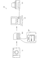
図1は、本実施例における画像処理システムの概略構成の一例を示す説明図である。本実施例の画像処理システム10は、画像ファイル生成装置としてのデジタルスチルカメラ11と、画像ファイルを格納する媒体としてのメモリカードMCと、画像処理装置としてのパーソナルコンピュータ12と、画像出力装置としてのカラープリンタCPとから構成される。
A. Image processing system configuration:
FIG. 1 is an explanatory diagram illustrating an example of a schematic configuration of an image processing system according to the present exemplary embodiment. The
デジタルスチルカメラ11は、ユーザ所望の画像処理モードや、画像データ内の特定の部位情報などを画像処理制御データPIM内に設定できる。画像処理モードとは、例えば階調補正やぼかし処理などの画像処理の方法を意味する。部位情報とは、パーソナルコンピュータ12などの画像処理処置が画像処理を行う際に参照する画像データ内の特定の部位を示す情報である。デジタルスチルカメラ11は、画像を撮影して得られた画像データと画像処理制御データPIMとを一体的に備える画像ファイルを生成する。生成した画像ファイルGFはメモリカードMCに格納される。
The digital
パーソナルコンピュータ12は、画像処理機能を有している。パーソナルコンピュータ12は、メモリカードMCを介して、あるいは図示しないケーブルを介してデジタルスチルカメラから画像ファイルGFを入力し、画像ファイルGFに含まれる画像処理制御データPIMを解析する。画像処理制御データPIMには、部位情報が含まれるので、これを参照してユーザ所望の画像処理を施す。画像処理が施された画像データは、カラープリンタCPに転送され、印刷が行われる。
The
以上のように、本実施例の画像処理システム10では、デジタルスチルカメラ11側からパーソナルコンピュータ12における画像処理を制御して、ユーザが所望した画像処理を自動的に施すことができる。デジタルスチルカメラ11、画像ファイルGF、パーソナルコンピュータ12についての詳細は後述する。なお、ここではパーソナルコンピュータ12が画像処理機能を有しているとしたが、むろんカラープリンタCPに画像処理機能を具備してもよい。
As described above, in the
画像処理システム10は、種々の態様を採ることができる。図2は、画像処理システム10のバリエーションを示す説明図である。画像処理システム10は、図1に示したデジタルスチルカメラ11やパーソナルコンピュータ12、カラープリンタCPの他に、画像処理機能を内蔵したディスプレイDPやサーバーSVを含むことができる。これらは、ケーブルCVあるいは無線通信で、直接あるいはネットワークNEを介して接続され、データのやり取りを行う。画像ファイル生成装置として、スキャナーやデジタルビデオカメラを接続することも可能である。
The
B.画像ファイル生成装置:
図3は、デジタルスチルカメラの概略構成を示すブロック図である。デジタルスチルカメラ11は、光の情報をデジタルデバイス(CCDや光電子倍管)に結像させることにより画像を取得するカメラである。デジタルスチルカメラ11は、光情報を収集するためのCCD等を備える光学回路111と、光学回路111を制御して画像を取得するための画像取得回路112と、取得したデジタル画像を加工するための画像加工回路113と、各回路を制御する制御部114とを備えている。制御部114は、内部にCPU、RAM、ROMを備えるマイクロコンピュータとして構成されている。デジタルスチルカメラ11は、また、画像処理モードや部位情報の各種設定を行うための選択・決定ボタン116や、撮影画像をプレビューしたり、各種設定画面を表示するための液晶ディスプレイ117を備えている。
B. Image file generator:
FIG. 3 is a block diagram showing a schematic configuration of the digital still camera. The digital
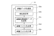
図4は、デジタルスチルカメラ11の機能ブロックを示す説明図である。デジタルスチルカメラ11は、画像データを生成する画像データ生成部11aと、画像データ内で特定の部位を指定する部位指定部11bと、画像処理制御データを生成する画像処理制御データ生成部11cと、画像データと画像処理制御データとを含む画像ファイルを生成する画像ファイル生成部11dと、生成された画像ファイルを出力する画像ファイル出力部11eを備えている。
FIG. 4 is an explanatory diagram showing functional blocks of the digital
ユーザによって選択・決定ボタン116を用いて設定された各種情報は、画像処理制御データ生成部11cによって画像処理制御データ内に設定され、画像データとともに一体的に画像ファイルとしてメモリカードMC内に格納される。なお、画像処理制御データには、先に示した画像処理モードや部位情報の他に、デジタルスチルカメラ11のガンマ値、ターゲット色空間や、撮影時に設定された露出時間、ホワイトバランス、絞り、シャッタースピード、レンズの焦点距離等の情報も含まれ得る。これらの情報は画像処理装置にて画像処理を施す際に適宜参照される。
Various types of information set by the user using the selection /
デジタルスチルカメラ11は、上述のように、取得した画像をデジタルデータとして記憶装置としてのメモリカードMCに保存する。デジタルスチルカメラ11における画像データの保存形式としては、JPEG形式が一般的であるが、この他にもTIFF形式、GIF形式、BMP形式等の保存形式が用いられ得る。
As described above, the digital
C.画像ファイルの構成:
図5は、画像ファイルGFの構成の一例を概念的に示す説明図である。画像ファイルGFは、デジタルスチルカメラ用画像ファイルフォーマット規格であるExifに従ったファイル構造を有している。Exifファイルの仕様は、電子情報技術産業協会(JEITA)によって定められている。
C. Image file structure:
FIG. 5 is an explanatory diagram conceptually showing an example of the configuration of the image file GF. The image file GF has a file structure according to Exif, which is an image file format standard for digital still cameras. Exif file specifications are defined by the Japan Electronics and Information Technology Industries Association (JEITA).
画像ファイルGFは、画像データを格納する画像データ格納領域101と、格納されている画像データに関する各種付属情報を格納する付属情報格納領域102とを備えている。画像データ格納領域101には、画像データがJPEG形式で格納される。付属情報格納領域には、付属情報がTIFF形式で格納される。付属情報格納領域102は、MakerNoteデータ格納領域103を備えている。MakerNoteデータ格納領域103は、デジタルスチルカメラ11のメーカーに開放されている未定義領域である。本実施例における画像処理制御データPIMは、MakerNoteデータ格納領域103に格納されている。なお、当業者にとって周知であるように、Exif形式のファイルでは、各データを特定するためにタグが用いられており、MakerNoteデータ格納領域103に格納されているデータに対してはタグ名としてMakerNoteが割り当てられ、MakerNoteタグと呼ばれている。
The image file GF includes an image
図6は、画像ファイルGFの詳細な階層構造を示す説明図である。図6(a)は、MakerNoteデータ格納領域103のデータ構造を示している。図6(b)は、MakerNoteデータ格納領域103内に定義されているPrintMatchingデータ格納領域104を示している。PrintMatchingデータが画像処理制御データPIMに相当する。
FIG. 6 is an explanatory diagram showing a detailed hierarchical structure of the image file GF. FIG. 6A shows the data structure of the MakerNote
画像ファイルGFのMakerNoteデータ格納領域103もまた、タグによって格納されているデータを識別できる構成を備えており、画像処理制御データPIMにはPrintMatchingのタグが割り当てられている。MakerNoteデータ格納領域103の各タグは、MakerNoteデータ格納領域103のトップアドレスからのオフセット値でポインタにより指定される。MakerNoteデータ格納領域103には、トップアドレスにメーカー名(6バイト)、続いて予約領域(2バイト)、ローカルタグのエントリ数(2バイト)、各ローカルタグオフセット(12バイト)の情報が格納されている。メーカー名の後には、文字終端列を示す00x0の終端コードが付されている。
The MakerNote
PrintMatchingデータ格納領域104には、PrintMatchingパラメータが格納されていることを示すPrintMatching識別子や、指定されているパラメータ数を示すパラメータ指定数、予めパラメータ毎に割り振られているパラメータ番号を指定する値が格納されるパラメータ番号、指定されたパラメータ番号のパラメータの設定値が格納されているパラメータ設定値の情報、などが格納されている。パラメータ番号は、例えば、2バイトの領域に格納される情報であり、パラメータ設定値は、4バイトの領域に格納される情報である。画像処理装置側では、このPrintMatchingタグを指標として画像処理制御データPIM(各パラメータ値)を取得することができる。
The PrintMatching
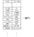
図7は、PrintMatchingデータの一例を概念的に示す説明図である。図示するように、MakerNoteデータ格納領域103には、ガンマ値、色空間、コントラスト、明るさ、カラーバランス、彩度、後述する部位情報などの画像処理制御データPIM等が格納される。
FIG. 7 is an explanatory diagram conceptually illustrating an example of PrintMatching data. As illustrated, the MakerNote
なお、本実施例では、画像ファイルGFは、Exif形式のファイルであるものとして説明したが、もちろんこれに限られるものではない。画像データと画像処理制御データとを一体的に備える構造を採っていればよい。 In the present embodiment, the image file GF has been described as an Exif format file, but the present invention is not limited to this. It is only necessary to adopt a structure in which image data and image processing control data are integrally provided.
D.画像処理制御データの生成処理:
(D1)画像処理モードの設定
上述した画像ファイルGFの生成に先立って、デジタルスチルカメラ11には画像処理制御データPIMが入力される。画像処理制御データPIMには、ガンマ値やターゲット色空間、露出時間、ホワイトバランス、絞り、シャッタースピード、画像処理モード、部位情報などの各種パラメータを設定可能である。その中で、図8は、画像処理モードを設定するためのグラフィカル・ユーザ・インターフェース(GUI)を示す説明図である。本図はデジタルスチルカメラに具備された液晶ディスプレイ117に表示される画面を表したものであり、その操作には選択・決定ボタン116を用いることが可能である。まず、図8の上方に示すとおり、「画像処理モード」を選択した後、「決定」ボタンを押すと、図8の下方に示すように各種画像処理モードを選択することができる。本図では「階調補正」を選択した場合を例示した。さらに「決定」ボタンを押すことにより、選択された画像処理モードが画像処理制御データPIMに設定される。設定された画像処理制御データPIMは、揮発的あるいは不揮発的に制御部114内のRAMあるいはROMに保存される。ここで、「階調補正」、「ぼかし処理」が選択されたときは、各処理で参照する部位の指定に移行する。なお、前記ROMは、PROM、EPROM、EEPROMなどの各種書き換え可能なROMでもよい。
D. Image processing control data generation processing:
(D1) Setting of Image Processing Mode Prior to generation of the image file GF described above, image processing control data PIM is input to the digital
(D2)部位情報の設定
次に、画像処理制御データPIMの一部である部位情報の設定方法を説明する。図9は、画像内に特定の部位を指定するためのGUIの一例を示す説明図ある。ユーザは、選択・決定ボタン116を用いることにより、まず、第1の座標P1を液晶ディスプレイ117内で指定する。つづいて、第2の座標P2を指定することにより、矩形領域である部位Aを指定することができる。次に、「決定」ボタンを押すことにより、指定された部位Aの座標を示すP1(x,y)およびP2(xx,yy)が、部位情報として画像処理制御データPIMに設定され、制御部114内のRAMあるいはROMに保存される。なお、「決定」ボタンではなく、「キャンセル」ボタンを選択すれば、何度でも部位を指定しなおすことができる。
(D2) Setting of Part Information Next, a method for setting part information that is a part of the image processing control data PIM will be described. FIG. 9 is an explanatory diagram showing an example of a GUI for designating a specific part in an image. The user first designates the first coordinate P1 in the
部位情報の設定方法は、上述の方法に限られることはなく、他の方法でも設定可能である。図10は、画像内に部位を指定するためのGUIの他の一例を示す説明図である。図10では、予め設定されたパターンに従い、液晶ディスプレイ117内の領域をa1からa9までの9つの領域に分割している。ユーザは選択・決定ボタン116を用い、この領域の中で少なくとも1つの領域を選択する。本実施例の場合では領域a5を選択している。領域を選択した後、「決定」ボタンを押すことにより、その領域に対応した座標が部位情報として画像処理制御データPIM内に設定される。なお、座標に代えて、領域に固有に付された番号等を用いてもよい。部位情報が設定された画像処理制御データPIMは、制御部114内のRAMあるいはROMに保存される。
The method for setting the part information is not limited to the method described above, and can be set by other methods. FIG. 10 is an explanatory diagram showing another example of a GUI for designating a part in an image. In FIG. 10, the area in the
部位情報とは領域としての情報だけではなく、1点の座標としての情報でもよい。図11は、画像内に部位を指定するためのGUIの他の一例を示す説明図である。ユーザは選択・決定ボタン116を用いて液晶ディスプレイ117内の十字カーソル120等を操作し、座標P3(x,y)を指定する。指定された座標は、部位情報として画像処理制御データPIM内に設定され、部位情報が設定された画像処理制御データPIMは、制御部114内のRAMあるいはROMに保存される。
The part information may be not only information as a region but also information as coordinates of one point. FIG. 11 is an explanatory diagram illustrating another example of a GUI for designating a part in an image. The user operates the
部位情報を設定する際に、上述のような座標の指定を毎回行うことは、ユーザーにとって大変煩わしい作業である。そのため、指定する座標の初期値をデジタルスチルカメラの焦点位置とすると好適である。この初期値は、ユーザの操作により変更可能であり、焦点位置以外の座標を初期値とすることも可能である。 It is very troublesome for the user to specify the coordinates as described above every time when setting the part information. For this reason, it is preferable that the initial value of the designated coordinates is the focal position of the digital still camera. This initial value can be changed by a user's operation, and coordinates other than the focal position can be used as the initial value.
F.画像ファイルの生成処理:
次に、画像ファイルの生成処理について説明する。図12は、デジタルスチルカメラ11における画像ファイルの生成処理の流れを示すフローチャートである。制御部114内のCPUは、ユーザからの撮影要求、例えば、シャッターボタンの押し下げに応じて、光学回路111と画像取得回路112を制御し、画像データGDを生成する(ステップS100)。CPUは生成された画像データGDを、一旦、制御部114内のRAMに保存する。次に、RAM内に保存された画像データGDを基に液晶ディスプレイ117上に画像を表示する。ユーザは上述した各種方法により、画像処理モードを選択し(ステップS110)、液晶ディスプレイ117内に表示された画像を参照して部位を指定する(ステップS120)。CPUは、選択された画像処理モードと指定された部位情報を基に画像処理制御データPIMを生成する(ステップS130)。このとき、自動で、あるいは手動で設定された他のパラメータを画像処理制御データPIMに含めてもよい。CPUは、生成した画像処理制御データPIMをRAMに保存する。最後に、CPUは、RAMに保存した画像データGDと画像処理制御データPIMとを一体的に結合し、1つの画像ファイルGFを生成し(ステップS140)画像ファイルの生成工程を終了する。
F. Image file generation processing:
Next, image file generation processing will be described. FIG. 12 is a flowchart showing the flow of image file generation processing in the digital
以上の工程によって画像ファイルGFは生成され、最終的に、生成された画像ファイルGFはメモリカードMCに格納される。なお、本実施例では、画像データGDを生成してから画像処理モードや部位情報などを含む画像処理制御データPIMを生成したが、画像処理制御データPIMを生成してから画像データGDを生成しても構わない。この場合、液晶ディスプレイ117上に画像が表示されないこともあり得る。
The image file GF is generated by the above steps, and finally the generated image file GF is stored in the memory card MC. In this embodiment, the image processing control data PIM including the image processing mode and the part information is generated after the image data GD is generated. However, the image data GD is generated after the image processing control data PIM is generated. It doesn't matter. In this case, an image may not be displayed on the
F.画像処理装置による画像処理:
次に、パーソナルコンピュータ12内で行う画像処理の詳細を説明する。図13は、画像処理装置としてのパーソナルコンピュータ12における画像処理の流れを示すフローチャートである。パーソナルコンピュータ12は、メモリカードMCやケーブルCVを介し、デジタルスチルカメラ11から画像ファイルGFを入力する(ステップS200)。続いて、入力した画像ファイルGFから、画像データGDと画像処理制御データPIMを抽出する(ステップS210、ステップS220)。次に、パーソナルコンピュータ12は、抽出した画像処理制御データPIMを解析し(ステップS230)、解析した画像処理制御データPIMに基づき画像データGDに対し後述する各種画像処理を行い(ステップS240)、画像処理を終了する。
F. Image processing by image processing device:
Next, details of image processing performed in the
(F1)階調補正
図13のステップS240における画像処理は、様々な態様が考えられ得るが、ここでは特に階調補正処理について説明する。図14は、画像処理装置としてのパーソナルコンピュータ12内おける階調補正処理の流れを示すフローチャートである。パーソナルコンピュータ12は、画像データGDを予め設定した領域に分割し、各領域における画像の輝度平均値Yaveを求める(ステップS300)。通常、画像データGDは、YCbCr色空間を用いたJPEG形式で記録されているため、輝度平均値Yaveは、その領域内の各画素のY値を加算し、領域内の全画素数で除することにより求めることができる。その後、部位情報により指定された部位を含む領域(指定領域SA)の輝度平均値を輝度基準値Ystdとして決定する(ステップS310)。本実施例では、図10におけるa5を指定領域SAとした。
(F1) Gradation Correction Although various modes can be considered for the image processing in step S240 in FIG. 13, here, the gradation correction processing will be particularly described. FIG. 14 is a flowchart showing the flow of gradation correction processing in the
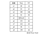
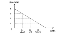
パーソナルコンピュータ12が、画像データGDに階調補正を施すにあたり、より効果的な階調補正を行うためには、先に決定した輝度基準値Ystdからかけ離れた輝度平均値Yaveを持つ領域を、以後の計算から省く必要がある。そのため、指定領域SAから各領域までの距離に応じた閾値を設定する(ステップS320)。図15は、指定領域SAの中心点から他の領域の中心点までの距離Lを示す図である。図17は、距離Lに対応した閾値Thを示すグラフである。本図に示すように、指定領域SAから遠い領域ほど、不要領域として除外されやすくなるように閾値Thを設定する。図16は、各領域における輝度平均値Yaveと、輝度平均値Yaveと輝度基準値Ystdとの差の絶対値Difを示す表である。パーソナルコンピュータ12は、各領域について、輝度平均値Yaveと輝度基準値Ystdとの差の絶対値Difを計算する(ステップS330)。絶対値Difと、その距離における閾値Thとを比較し(ステップS340)、絶対値Difが閾値を超えた場合、その領域を不要領域FAとし、以後の計算からその領域を除外する(ステップS350)。本実施例の場合、図17を見ると、a3,a6,a9の領域が除外されることがわかる。
In order to perform more effective gradation correction when the
次に、不要領域FA以外の領域(有効領域HA)と指定領域SAとの距離によって重みづけを施した画像データGD全体の輝度平均値Yave’を求める(ステップS360)。図18は、指定領域SAから有効領域HAまでの距離に対する重みづけWの関係を示すグラフである。指定領域a5に対する各領域の重みづけWを、本図のように、
a5:(a2,a8):a4:(a1,a7)=4:3:2:1
とすれば、次式によりYave’を求めることができる。
ΣYave=a5*4+(a2+a8)*3+a4*2+(a1+a7)*1
Yave’=ΣYave/(1*4+2*3+1*2+2*1)
なお、閾値Thおよび重みづけWは任意の値である。
Next, the luminance average value Yave ′ of the entire image data GD weighted by the distance between the area other than the unnecessary area FA (effective area HA) and the designated area SA is obtained (step S360). FIG. 18 is a graph showing the relationship of the weight W with respect to the distance from the designated area SA to the effective area HA. The weight W of each area for the designated area a5 is as shown in the figure.
a5: (a2, a8): a4: (a1, a7) = 4: 3: 2: 1
Then, Yave ′ can be obtained by the following equation.
ΣYave = a5 * 4 + (a2 + a8) * 3 + a4 * 2 + (a1 + a7) * 1
Yave '= ΣYave / (1 * 4 + 2 * 3 + 1 * 2 + 2 * 1)
Note that the threshold Th and the weight W are arbitrary values.
最後に、重みづけを施した輝度平均値Yave’を用い、画像データGD全体に対し階調補正を行う(ステップS370)。不要領域FAを含む画像データ全体の輝度平均値をYallとし、画像データGDの各画素の輝度をYgとすると、新たな各画素の輝度Yg’は次式によって求めることができる。
Yg’=Yg*Yave’/Yall
この計算を全画素について行い、新たな画像データを生成し、パーソナルコンピュータ12は階調補正を終了する。
Finally, gradation correction is performed on the entire image data GD using the weighted luminance average value Yave ′ (step S370). If the average luminance value of the entire image data including the unnecessary area FA is Yall and the luminance of each pixel of the image data GD is Yg, the new luminance Yg ′ of each pixel can be obtained by the following equation.
Yg '= Yg * Yave' / Yall
This calculation is performed for all pixels to generate new image data, and the
(F2)ぼかし処理
次に、図13のステップS240における画像処理の他の態様であるぼかし処理について説明する。図19は、画像処理装置としてのパーソナルコンピュータ12における、ぼかし処理の流れを示すフローチャートである。なお、本実施例において、指定部位は1点の座標(指定座標SZ)とする。まず、パーソナルコンピュータ12は、ぼかし処理を行う画素と指定座標SZとの距離Lを測定する(ステップS400)。次に、図20のグラフに示すような関数により、距離Lに応じた行列成分値xを得る(ステップS410)。続いて、ぼかし処理を施す画素BPを中心とする周囲9点について、以下に示す行列演算を行い新たな画素値BP’を得る。

以上、本実施例に従うパーソナルコンピュータ12によれば、先に説明したデジタルスチルカメラ11によって生成された画像ファイルGFの画像データGDに対し、所望の画像処理を施すことができる。
As described above, according to the
G.画像ファイル編集装置:
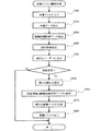
最後に、画像ファイル編集装置について説明する。画像ファイル編集装置は、既に画像処理制御データPIMが設定された画像ファイルに対し、後から画像処理制御データPIMを修正し、再設定することができる装置である。本実施例では、画像処理制御データPIMの中で、特に部位情報の編集について説明する。図21は、画像ファイル編集装置における画像処理制御データPIMの編集処理の流れを示すフローチャートである。まず、画像処理制御装置は、画像ファイルGFをメモリカードMCやケーブルCVを介し入力する(ステップS500)。次に、画像ファイルGFを解析し、画像データGDと画像処理制御データPIMとを抽出する(ステップS510、ステップS520)。さらに画像処理制御データPIMから部位情報を抽出し(ステップS530)、画像ファイル生成装置によって指定された部位(指定部位)を画像ファイル編集装置のユーザに提示する(ステップS540)。ユーザは、提示された指定部位を変更したい場合、新たな部位を指定する(ステップS550)。変更しない場合はそのまま処理を終了する。画像ファイル編集装置は、新たに指定された部位を部位情報として画像処理制御データ内に設定する(ステップS560)。最後に、先に抽出した画像データと新たな画像処理制御データとを一体的に結合し、新たな画像ファイルを得る(ステップS570)。画像処理制御装置は、新たな画像ファイルをメモリカードMCやケーブルCVを介し出力し(ステップS580)、画像ファイル編集処理を完了する。
G. Image file editing device:
Finally, the image file editing apparatus will be described. The image file editing device is a device capable of correcting and resetting the image processing control data PIM later on the image file in which the image processing control data PIM has already been set. In this embodiment, editing of part information will be described in the image processing control data PIM. FIG. 21 is a flowchart showing a flow of editing processing of the image processing control data PIM in the image file editing apparatus. First, the image processing control apparatus inputs the image file GF via the memory card MC or the cable CV (step S500). Next, the image file GF is analyzed, and the image data GD and the image processing control data PIM are extracted (steps S510 and S520). Further, part information is extracted from the image processing control data PIM (step S530), and the part (designated part) designated by the image file generation device is presented to the user of the image file editing device (step S540). When the user wants to change the designated part that is presented, the user designates a new part (step S550). If no change is made, the process is terminated. The image file editing apparatus sets the newly designated part as part information in the image processing control data (step S560). Finally, the previously extracted image data and new image processing control data are integrally combined to obtain a new image file (step S570). The image processing control apparatus outputs a new image file via the memory card MC or the cable CV (step S580), and completes the image file editing process.
なお、画像ファイル編集装置としての具体的な態様は、画像ファイルが編集できる装置であればよく、デジタルスチルカメラやパーソナルコンピュータ、プリンタなど各種考えられ得る。この場合、ユーザが新たな部位を指定するために、液晶ディスプレイやディスプレイ等の表示装置、マウスやキーボード等の入力装置を備えていることが好適である。 The specific mode of the image file editing device may be any device that can edit an image file, and various types such as a digital still camera, a personal computer, and a printer can be considered. In this case, it is preferable that the user has a display device such as a liquid crystal display or a display and an input device such as a mouse or a keyboard in order to designate a new part.
以上、本実施例に従う画像ファイル編集装置によれば、先に説明したデジタルスチルカメラ11によって生成された画像ファイルGFの画像処理制御データPIMを編集し、再設定することができる。
As described above, according to the image file editing apparatus according to the present embodiment, the image processing control data PIM of the image file GF generated by the digital
以上、実施例に基づき本発明に係る画像ファイル生成装置、画像処理装置、画像ファイル編集装置を説明してきたが、上述した発明の実施の形態は、本発明の理解を容易にするためのものであり、本発明を限定するものではない。本実施例では、部位情報を設定する際、一箇所の部位を指定した場合のみを説明したが、複数の部位を指定してもよい。また、ソフトウェアで実現している機能をハードウェアで実現してもよいし、その逆ももちろん可能である。その他にも、本発明は、その趣旨並びに特許請求の範囲を逸脱することなく、変更、改良され得ると共に、本発明にはその等価物が含まれることはもちろんである。 As described above, the image file generating device, the image processing device, and the image file editing device according to the present invention have been described based on the embodiments. There is no limitation to the present invention. In the present embodiment, only the case where one part is specified when setting the part information has been described, but a plurality of parts may be specified. In addition, functions realized by software may be realized by hardware, and vice versa. In addition, the present invention can be changed and improved without departing from the spirit and scope of the claims, and it is needless to say that the present invention includes equivalents thereof.
10…画像処理システム
11…デジタルスチルカメラ
11a…画像データ生成部
11b…部位指定部
11c…画像処理制御データ生成部
11d…画像ファイル生成部
11e…画像ファイル出力部
12…パーソナルコンピュータ
100…画像ファイル
101…画像データ格納領域
102…付属情報格納領域
111…光学回路
112…画像取得回路
114…制御部
116…選択・決定ボタン
117…液晶ディスプレイ
120…十字カーソル
DESCRIPTION OF
Claims (3)
前記画像ファイルに含まれる前記部位情報に基づき、前記画像ファイルに含まれる前記画像処理モードが表す前記所定の画像処理を、前記画像ファイルに含まれる前記画像データに対して行う画像処理手段と、
前記画像データを所定の領域に分割する領域分割手段と、
前記分割されたそれぞれの領域の輝度平均値を算出する輝度平均値算出手段と、
前記分割されたそれぞれの領域のうち、領域の輝度平均値と前記部位を含む領域の輝度平均値との差分の絶対値が所定の閾値を超えない領域の輝度平均値を用いて、前記画像データ全体の輝度平均値を算出する全体輝度平均値算出手段と、
を有し、
前記所定の画像処理は階調補正処理であり、
前記画像処理手段は、前記算出された前記画像データ全体の輝度平均値に基づいて、前記階調補正処理を行う
画像処理装置。 Image file input means for inputting image data, part information representing a predetermined part in the image represented by the image data, and an image file including an image processing mode representing predetermined image processing;
Image processing means for performing the predetermined image processing represented by the image processing mode included in the image file on the image data included in the image file based on the part information included in the image file;
Area dividing means for dividing the image data into predetermined areas;
A luminance average value calculating means for calculating a luminance average value of each of the divided areas;
Among the divided areas, the image data is obtained by using the brightness average value of the area where the absolute value of the difference between the brightness average value of the area and the brightness average value of the area including the portion does not exceed a predetermined threshold value. An overall brightness average value calculating means for calculating an overall brightness average value;
Have
The predetermined image processing is gradation correction processing;
The image processing device, wherein the image processing unit performs the gradation correction processing based on the calculated average brightness value of the entire image data.
前記所定の閾値は、前記部位を含む領域からの距離に応じた閾値である
画像処理装置。 The image processing apparatus according to claim 1 ,
The image processing apparatus according to claim 1, wherein the predetermined threshold is a threshold corresponding to a distance from an area including the part.
前記全体輝度平均値算出手段は、前記部位を含む領域からの距離に応じた重み付けを施して前記画像データ全体の輝度平均値を算出する
画像処理装置。 The image processing apparatus according to claim 1 ,
The overall luminance average value calculation means calculates an average luminance value of the entire image data by applying a weight according to a distance from an area including the part.
Priority Applications (1)
| Application Number | Priority Date | Filing Date | Title |
|---|---|---|---|
| JP2007142006A JP4697186B2 (en) | 2007-05-29 | 2007-05-29 | Image processing device |
Applications Claiming Priority (1)
| Application Number | Priority Date | Filing Date | Title |
|---|---|---|---|
| JP2007142006A JP4697186B2 (en) | 2007-05-29 | 2007-05-29 | Image processing device |
Related Parent Applications (1)
| Application Number | Title | Priority Date | Filing Date |
|---|---|---|---|
| JP2001184374A Division JP4006961B2 (en) | 2001-06-19 | 2001-06-19 | Image file generator |
Publications (3)
| Publication Number | Publication Date |
|---|---|
| JP2007305139A JP2007305139A (en) | 2007-11-22 |
| JP2007305139A5 JP2007305139A5 (en) | 2008-07-31 |
| JP4697186B2 true JP4697186B2 (en) | 2011-06-08 |
Family
ID=38838953
Family Applications (1)
| Application Number | Title | Priority Date | Filing Date |
|---|---|---|---|
| JP2007142006A Expired - Fee Related JP4697186B2 (en) | 2007-05-29 | 2007-05-29 | Image processing device |
Country Status (1)
| Country | Link |
|---|---|
| JP (1) | JP4697186B2 (en) |
Families Citing this family (3)
| Publication number | Priority date | Publication date | Assignee | Title |
|---|---|---|---|---|
| JP4538386B2 (en) | 2005-07-06 | 2010-09-08 | 富士フイルム株式会社 | Target image recording apparatus, imaging apparatus, and control method thereof |
| JP2009182784A (en) * | 2008-01-31 | 2009-08-13 | Casio Comput Co Ltd | Image transmission system, image storage device, and program |
| JP4974950B2 (en) * | 2008-04-16 | 2012-07-11 | キヤノン株式会社 | Communication system, information processing apparatus, imaging apparatus, program |
Citations (1)
| Publication number | Priority date | Publication date | Assignee | Title |
|---|---|---|---|---|
| JP2001128044A (en) * | 1999-10-26 | 2001-05-11 | Minolta Co Ltd | Digital camera, reproduced picture display device and filing method of picture data |
Family Cites Families (1)
| Publication number | Priority date | Publication date | Assignee | Title |
|---|---|---|---|---|
| JPS6428786A (en) * | 1987-07-24 | 1989-01-31 | Canon Kk | Information processor |
-
2007
- 2007-05-29 JP JP2007142006A patent/JP4697186B2/en not_active Expired - Fee Related
Patent Citations (1)
| Publication number | Priority date | Publication date | Assignee | Title |
|---|---|---|---|---|
| JP2001128044A (en) * | 1999-10-26 | 2001-05-11 | Minolta Co Ltd | Digital camera, reproduced picture display device and filing method of picture data |
Also Published As
| Publication number | Publication date |
|---|---|
| JP2007305139A (en) | 2007-11-22 |
Similar Documents
| Publication | Publication Date | Title |
|---|---|---|
| JP4406195B2 (en) | Output image adjustment of image data | |
| KR101351091B1 (en) | Image forming apparatus and control method of consecutive photographing image | |
| JP2005215750A (en) | Face detecting device and face detecting method | |
| US8957991B2 (en) | Imaging apparatus, image processing method and computer program for smoothing dynamic range of luminance of an image signal, color conversion process | |
| JP2007329620A (en) | Imaging device and video signal processing program | |
| JP4697186B2 (en) | Image processing device | |
| JP2005318561A (en) | Image output system, method, apparatus, and program | |
| JP2007104249A (en) | Image correcting apparatus, image correcting method, program and recording medium | |
| JP2007188238A (en) | Print order system, order accepting server and image processing method | |
| JP4006961B2 (en) | Image file generator | |
| JP4007334B2 (en) | Image file generator | |
| JP6210772B2 (en) | Information processing apparatus, imaging apparatus, control method, and program | |
| JP4315024B2 (en) | Digital camera and program | |
| JP2007174015A (en) | Image management program and image management apparatus | |
| JP4600503B2 (en) | Output image adjustment of image data | |
| JP5888442B2 (en) | Image data output adjustment apparatus, image data output adjustment method, image data output adjustment program, and imaging apparatus | |
| JP2006525746A (en) | Image quality improving method and apparatus for improving images based on stored preferences | |
| JP3858859B2 (en) | Image data output adjustment | |
| JPH11262030A (en) | Digital still camera and its operation control method | |
| JP4270204B2 (en) | Image data output adjustment | |
| JP2021150854A (en) | Imaging apparatus, control method of imaging apparatus, image capturing system, and program | |
| JP4232360B2 (en) | Image file generation device, image processing device, and image file editing device | |
| JP2010118850A (en) | Image processor, imaging apparatus, and program | |
| JP2006287516A (en) | Camera apparatus, photographing method, and photographing program | |
| JP4807399B2 (en) | Image file generation apparatus and image file generation method |
Legal Events
| Date | Code | Title | Description |
|---|---|---|---|
| A521 | Request for written amendment filed |
Free format text: JAPANESE INTERMEDIATE CODE: A523 Effective date: 20080617 |
|
| A621 | Written request for application examination |
Free format text: JAPANESE INTERMEDIATE CODE: A621 Effective date: 20080617 |
|
| A977 | Report on retrieval |
Free format text: JAPANESE INTERMEDIATE CODE: A971007 Effective date: 20101111 |
|
| A131 | Notification of reasons for refusal |
Free format text: JAPANESE INTERMEDIATE CODE: A131 Effective date: 20101124 |
|
| A521 | Request for written amendment filed |
Free format text: JAPANESE INTERMEDIATE CODE: A523 Effective date: 20110113 |
|
| A01 | Written decision to grant a patent or to grant a registration (utility model) |
Free format text: JAPANESE INTERMEDIATE CODE: A01 Effective date: 20110201 |
|
| A61 | First payment of annual fees (during grant procedure) |
Free format text: JAPANESE INTERMEDIATE CODE: A61 Effective date: 20110214 |
|
| LAPS | Cancellation because of no payment of annual fees |