JP4695830B2 - Area map providing device for moving body - Google Patents
Area map providing device for moving body Download PDFInfo
- Publication number
- JP4695830B2 JP4695830B2 JP2003379293A JP2003379293A JP4695830B2 JP 4695830 B2 JP4695830 B2 JP 4695830B2 JP 2003379293 A JP2003379293 A JP 2003379293A JP 2003379293 A JP2003379293 A JP 2003379293A JP 4695830 B2 JP4695830 B2 JP 4695830B2
- Authority
- JP
- Japan
- Prior art keywords
- route
- map
- area
- data
- map information
- Prior art date
- Legal status (The legal status is an assumption and is not a legal conclusion. Google has not performed a legal analysis and makes no representation as to the accuracy of the status listed.)
- Expired - Fee Related
Links
- 238000000034 method Methods 0.000 description 34
- 238000013500 data storage Methods 0.000 description 12
- 238000004891 communication Methods 0.000 description 5
- 239000000470 constituent Substances 0.000 description 5
- 238000000605 extraction Methods 0.000 description 4
- 238000007726 management method Methods 0.000 description 4
- 230000000284 resting effect Effects 0.000 description 4
- 238000005452 bending Methods 0.000 description 3
- 239000000284 extract Substances 0.000 description 3
- 230000002093 peripheral effect Effects 0.000 description 2
- 238000010586 diagram Methods 0.000 description 1
- 235000013410 fast food Nutrition 0.000 description 1
- 239000000446 fuel Substances 0.000 description 1
- 239000004973 liquid crystal related substance Substances 0.000 description 1
- 239000000463 material Substances 0.000 description 1
- 235000012054 meals Nutrition 0.000 description 1
- 230000000116 mitigating effect Effects 0.000 description 1
- XLYOFNOQVPJJNP-UHFFFAOYSA-N water Substances O XLYOFNOQVPJJNP-UHFFFAOYSA-N 0.000 description 1
Images


Classifications
-
- G—PHYSICS
- G01—MEASURING; TESTING
- G01C—MEASURING DISTANCES, LEVELS OR BEARINGS; SURVEYING; NAVIGATION; GYROSCOPIC INSTRUMENTS; PHOTOGRAMMETRY OR VIDEOGRAMMETRY
- G01C21/00—Navigation; Navigational instruments not provided for in groups G01C1/00 - G01C19/00
- G01C21/26—Navigation; Navigational instruments not provided for in groups G01C1/00 - G01C19/00 specially adapted for navigation in a road network
- G01C21/34—Route searching; Route guidance
- G01C21/36—Input/output arrangements for on-board computers
- G01C21/3667—Display of a road map
Description
本発明は、記録媒体から地図情報を抽出して、これを移動体へ提供する移動体用地図情報提供装置に関する。 The present invention relates to a map information providing device for a moving body that extracts map information from a recording medium and provides the extracted map information to a moving body.
目的地までの地図を表示するシステムにおいて、特に目的地までの経路沿いの領域の地図情報を抽出して表示する地図情報表示システムがある(例えば、特許文献1参照)このシステムは、移動体の通過経路、または予定経路に応じて領域の地図を抽出して、抽出した地図情報を表示するものであった。更に、ユーザから指定された地点については、ユーザが切り出す領域範囲を設定できる技術もある(特許文献2参照)。 In a system that displays a map to a destination, there is a map information display system that extracts and displays map information of an area along a route to the destination (see, for example, Patent Document 1). A map of the area is extracted according to the passage route or the planned route, and the extracted map information is displayed. Furthermore, there is a technique that can set an area range to be cut out by a user for a point designated by the user (see Patent Document 2).
提供される地図情報は通常直交座標系で記憶媒体等に記録管理されている。しかし、実際には地球は球面であるから、経路から特定の幅で領域を定めて抽出しようとしても、経路の位置する緯度によって、経度方向の長さに誤差が生じる。つまり、本来表示すべき所望の領域よりも狭い範囲の地図情報が抽出されるか、または逆に必要以上に広い範囲の地図情報が抽出される、という問題がある。 The provided map information is usually recorded and managed in a storage medium or the like in an orthogonal coordinate system. However, since the earth is actually a spherical surface, an error occurs in the length in the longitude direction depending on the latitude at which the route is located even if the region is extracted with a specific width from the route. That is, there is a problem that map information in a narrower range than a desired region to be originally displayed is extracted, or conversely, map information in a wider range than necessary is extracted.
また、経路の道路中心線の形状をもとに抽出する領域を定めると、領域を表す多角形が非常に多くの頂点を持つ。このため、記録される地図情報から領域の内部にある情報の判定処理に多くの時間を要し、結果として実用サービスに耐えうる性能が得られないという問題がある。 Further, when an area to be extracted is determined based on the shape of the road center line of the route, the polygon representing the area has a very large number of vertices. For this reason, it takes a lot of time to determine the information in the area from the recorded map information, and as a result, there is a problem that the performance that can withstand the practical service cannot be obtained.
さらには、画一的に定められる経路周辺領域のみの地図情報提供では、例えば途中の休憩地点等、立ち寄り地点などの情報が含まれない。よって、ユーザは所望の情報を得るために検索操作が再度必要となる。また、経路を表示した地図上でユーザが指定した地域を拡張して詳細な地図情報提供を行う方式もあるが、候補となる地域の提示がないために詳細な地図情報を提供するのに適切な地域を選定する操作が煩わしいという問題がある。 本発明は、上述の点に鑑みてなされたものであり、その目的とするところは、ユーザのニーズに応じ、かつ正確な地図データを迅速に移動体に提供することにある。より具体的には移動体の走行経路に沿った領域を、緯度による誤差を加味して適切に定め、かつ、実用上問題ない程度に抽出領域を簡略化することで、地図情報の抽出処理負荷を軽減する。本願の発明により、実用サービスに耐えうる性能を備える移動体用地図情報提供装置を提供することができる。 Furthermore, the provision of map information only for the route peripheral area determined uniformly does not include information such as a stop point on the way, for example, a stop point. Therefore, the user needs to perform a search operation again to obtain desired information. There is also a method of providing detailed map information by expanding the area specified by the user on the map displaying the route, but it is suitable for providing detailed map information because there is no candidate area presented There is a problem that the operation of selecting a region is troublesome. The present invention has been made in view of the above points, and an object of the present invention is to promptly provide a mobile object with accurate map data according to the needs of the user. More specifically, the map information extraction processing load is determined by appropriately determining the area along the travel route of the moving body, taking into account errors due to latitude, and simplifying the extraction area to the extent that there is no practical problem. Reduce. According to the invention of the present application, it is possible to provide a moving body map information providing device having performance capable of withstanding practical services.
本願で開示する代表的な発明は以下の通りである。
取得した2地点の情報に基づいて経路探索を行い、経路にそった領域の地図データを出力する地図データ提供装置。
特に地図データが直交座標系に基づくもので有る場合に、経路領域の生成の際に、経路の幅を所定の幅に該経路上の緯度値に基づいた補正を加えて決定する地図データ装置。
又、経路にそった領域の図形を、経路中の構成点を間引くことで簡略化した上で地図データを検索する領域を決定する地図データ装置。
更に、探索される経路周辺で経由地点を予測する経由地予測部を備え、領域を生成する際に、経由地点周辺として予測された箇所については上記領域より広い範囲で抽出する地図データ提供装置。
Representative inventions disclosed in the present application are as follows.
A map data providing device that performs a route search based on acquired information on two points and outputs map data of an area along the route.
A map data device that determines the width of a route by adding a correction based on a latitude value on the route to a predetermined width when generating a route region, particularly when the map data is based on an orthogonal coordinate system.
A map data device for determining a region for searching map data after simplifying a figure of a region along a route by thinning out constituent points in the route.
Furthermore, a map data providing device that includes a waypoint prediction unit that predicts waypoints around a route to be searched, and extracts a region predicted as the waypoint periphery in a wider range than the region when the region is generated.
本発明の特徴によれば、移動体経路に沿った地図情報を抽出する際に、ユーザの要求に応じた適切かつ正確な範囲の地図情報を提供することができる。かつ、地図の提供側の負担を軽減することができる。 According to the feature of the present invention, when extracting map information along a moving body route, map information in an appropriate and accurate range according to a user's request can be provided. In addition, the burden on the map provider can be reduced.
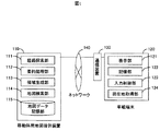
以下に、本発明の実施例について図面に基づいて説明する。図1は、本発明で示す第一の実施例である移動体用地図情報提供装置を示す。図1に示す移動体用地図情報提供装置110は、インターネット等のネットワーク140を介し、携帯電話等の通信装置130と接続された車載端末120に対して、地図情報を提供する。
Embodiments of the present invention will be described below with reference to the drawings. FIG. 1 shows a moving body map information providing apparatus according to a first embodiment of the present invention. The mobile map
移動体用地図提供装置110は、車載端末120の現在地と行き先(目的地)の2地点の情報を受け取る。経路探索部111は2地点間の経路を算出し、部算出された経路情報を表す折線図形要約処理部112が簡略化処理する。次に、要約処理部112が出力する簡略化経路情報をもとに、領域生成部113は経路沿いの領域を求め部、地図検索部114が後述の地図データ記憶部から求められた領域内に存在する図形のみを選択して出力する。部地図データ記憶部115は、地図データを直交座標系で記録して管理する。ここで、地図検索部114は例えば、空間検索処理機能を備えるデータベース管理システムを採用することができる。地図データ記憶部は、ハードディスクやDVDなどの記憶媒体に該当する。尚、地図データ記憶手段は、移動体用地図提供装置にネットワーク等を介して更に接続される外部記憶装置であっても良い。 車載端末120は例えば車載カーナビベーション装置に該当する。車載端末120は、液晶ディスプレイ等の表示部121と、ハードディスクやコンパクトフラッシュ(登録商標)等の記憶部122と、ユーザからの画面タッチ等の入力情報を制御する入力制御部123と、GPS等により現在地を測位する現在地取得部124を有する。ユーザは入力制御部によって表示部121に表示されるメニューから目的地を選択する。取得した現在地と目的地の条件をもとに移動体用地図提供装置110から配信される地図情報を、記憶部122は一旦記録し、表示部121に地図情報が表示される。
The moving body
以下の説明においては、移動体用地図提供装置110、及び車載端末120は、各々起動されており、通信装置130とネットワーク140を介して両者は接続処理されているものとする。上記2つの装置の各部は、各々の装置の制御管理部によって管理され実行されるものである。実行の方法は、記録媒体に記録されるソフトウェアプログラムの読み出し、ハードウェア、若しくは両者の協調による場合がある。 次に、地図データ記憶部115において管理するデータ構造について図6を用いて説明する。地図情報は例えば図6に示すようなデータ構成で、道路データ、店舗等のPOIデータ、及び公園や水域等の背景データを定義して、データベース管理システムのテーブルへ格納しておくものとする。道路テーブル610では、道路データを識別するID、道路の種別、中心線の折線図形を表す座標値列、道路名を表す名称からなるテーブル構造で定義して、道路データを管理する。
同様に、POIテーブル、背景テーブルでも、それぞれID、種別、位置や多角形領域を表す座標値(列)、名称といったテーブル構造で定義して、POIデータと背景データを管理する。
In the following description, it is assumed that the mobile
Similarly, in the POI table and the background table, the POI data and the background data are managed by defining the table structure such as the ID, type, position, coordinate value (column) representing the polygonal area, and name.
図2は、移動体用地図提供装置110において、経路領域の地図を抽出して提供する処理内容を示す図である。以下、前述の図1と図2を用いて、処理の流れを説明する。
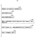
最初に、操作者に入力部を介した目的地の設定が行われ、現在位置取得部124により車載端末120の現在地の情報が取得される。これにより現在位置が始点として、目的地が終点として設定される。ユーザの要求によっては、現在の位置にかえて特定の場所の情報を用いても良いし、目的地は最終的な目的地でなくある任意の地点の情報が設定されれば良い。もちろん、中継地点の情報をさらに設定し、以下の経路検索に用いても良い。この始終点の情報が車載端末120から通信装置130とネットワーク140を介して移動体用地図提供装置110へ送られる。移動体用地図提供装置110では、受け取った始終点をもとに経路探索部111において、経路探索を実施し、始終点間の経路を求める。この結果、始点から終点への経路順に並んだ道路データのリストと、各道路データの座標値列が経路方向と一致するかを表す順逆フラグのリストが得られる。順逆フラグとは、道路データの座標値列の点の並びが経路方向と一致する場合を順方向、一致しない場合を逆方向として区別するための情報である(S210)。この経路探索の処理としては、例えばダイクストラ法を用いた最短経路探索を適用することができる。
FIG. 2 is a diagram showing the processing contents for extracting and providing a map of the route area in the mobile
First, the destination is set through the input unit for the operator, and the current location information of the in-
続いて、領域生成部113において、前述の道路データのリストを先頭から順に参照し、各道路データの順逆フラグに従って、経路方向と一致しない逆方向のフラグであった場合には座標値列の点の並びを逆転させる。次に、リスト中に並んだ道路データの座標値列の端点を経路順に接続して、一本の連続した経路の折線図形を求める。(S220)。ここで得られた折線図形を、要約処理部112において、特徴点間引き処理を行うことによって、経路の折線図形を簡略化する(S230)。この経路折線図形の簡略化処理については、後で図3を用いて詳述する。
Subsequently, the
続いて、簡略化した折線図形をもとに領域生成部113において、折線の各線分に経度方向成分の補正を加味した幅付け処理を行い、経路領域を求める(S240)。この幅付け処理については、後で図4及び図5を用いて詳述する。
Subsequently, in the
地図検索部114では、上記一連の処理によって定まった簡略化経路領域を空間検索条件として用いて、地図データ記憶部115に対して抽出処理を行う(S250)。これは例えば、地図検索部114が地図情報の格納されたテーブルに対して、前述の簡略化経路領域を表す多角形を条件に記したSQL形式の問い合わせ言語を用いて、空間検索処理を実施する。この結果として、条件とされた簡略化経路領域を表す多角形の内側に存在する道路データや背景データ、及びPOIデータ等の地図データ集合が得られる。以上の処理により得られた経路沿いの領域の地図データを、車載端末120へネットワーク140、通信装置130を介して出力する(S260)。車載端末側では、受信した情報に基づいて地図表示がなされる。
The
次に各処理における内容を詳述する。最初に、図2における経路の折線図形の簡略化処理(S230)について、図3を用いて説明する。 Next, the contents in each process will be described in detail. First, the process of simplifying the broken line figure of the route in FIG. 2 (S230) will be described with reference to FIG.
経路を表す折線図形は、一般に距離に応じて頂点数が膨大となる。例えば、経路探索の結果得られる道路データリストの要素数は距離に依存し、数百から時には数千に及ぶ場合がある。この場合、各道路データの座標値列を接続した折線図形の頂点数は、さらにその数倍の規模となる。よって、得られた経路を示す折れ線図形に幅付けした経路領域多角形の範囲から、該範囲に存在する道路データ、背景データ、POIデータ等の地図データを抽出する空間検索処理を行うと、経路領域多角形と地図データの座標値(列)が表す図形との間の交差及び包含判定処理に多大な処理時間を要する。この交差及び包含判定処理については、後で詳細に述べる。 A polygonal line figure representing a route generally has an enormous number of vertices depending on the distance. For example, the number of elements in the road data list obtained as a result of the route search depends on the distance, and may range from several hundred to several thousand. In this case, the number of vertices of the polygonal line figure connecting the coordinate value strings of each road data is several times that scale. Therefore, when a spatial search process is performed to extract map data such as road data, background data, and POI data existing in the range from the range of the path area polygon that is widened to the polygonal line figure indicating the obtained path, the path A large amount of processing time is required for the intersection and inclusion determination processing between the region polygon and the graphic represented by the coordinate values (columns) of the map data. This intersection and inclusion determination process will be described in detail later.
本発明では空間検索に先立って、折線図形の簡略化処理により、屈曲点を削減し、点数構成の少ない折線図形を求める。具体的には、図3の300に示すように、折線の始終点を結ぶ線分を求め、続いて各屈曲点からの垂線の長さが最長となる構成点Pnを求める。この垂線の長さをdnとする。なお、図3では点P6の垂線が最長となっていることを示している。続いて、構成点P6と始終点とを結ぶ線分を求め、同じく各構成点からの垂線が最長となる構成点を求める。このとき、最長垂線距離が、指定の許容誤差εより小さいとき、この屈曲点を削除する。これを繰り返し行うことによって、簡略化した折線図形が求められる。 In the present invention, prior to the space search, the bending points are reduced by the simplification processing of the broken line figure, and the broken line figure having a small number of points is obtained. Specifically, as indicated by 300 in FIG. 3, a line segment connecting the start and end points of the fold line is obtained, and subsequently, a constituent point Pn having the longest perpendicular from each bending point is obtained. Let dn be the length of this perpendicular. FIG. 3 shows that the perpendicular of the point P6 is the longest. Subsequently, a line segment connecting the constituent point P6 and the start / end point is obtained, and the constituent point having the longest perpendicular from each constituent point is also obtained. At this time, when the longest perpendicular distance is smaller than the specified tolerance ε, the bending point is deleted. By repeating this, a simplified broken line figure is obtained.
また上記以外にも、折線を構成する線分の長さが適宜定めた長さの閾値より小さい場合に、その線分の端点を削除する手法。又は、折線の各頂点における線分間の角度が鈍角を成す場合に、適宜定めた角度の閾値より大きい場合にその頂点を削除する手法を適用することができる。ただし、いずれの手法においても、頂点を削除した後に得られる折線図形の変更した箇所が、元の折線から許容誤差εより大きく移動している場合には、その頂点の削除は行わないという条件を備えていることが必要である。この条件によって、過度な簡略化によって元の経路が求めた経路領域の多角形から外れることを防ぐ。この簡略化された折線図形を用いることで、経路領域の決定処理の簡略化を図ることが可能となる。 In addition to the above, a method of deleting the end point of a line segment when the length of the line segment constituting the broken line is smaller than a length threshold determined as appropriate. Alternatively, when the angle between the line segments at each vertex of the broken line is an obtuse angle, a method of deleting the vertex when the angle is larger than a threshold value determined as appropriate can be applied. However, in either method, if the part of the polygonal line figure obtained after deleting the vertex has moved more than the allowable error ε from the original polygonal line, the condition is that the vertex is not deleted. It is necessary to have. This condition prevents the original route from deviating from the polygon of the obtained route region due to excessive simplification. By using this simplified broken line figure, it is possible to simplify the route area determination process.
続いて、図2における経路領域の多角形内に存在する道路データ、背景データ、及びPOIデータを地図データ記憶部から抽出する空間検索処理(S250)について、図10を用いて説明する。
空間検索処理には、多角形の空間検索を効率的に行うため、道路データ、背景データ、POIデータ等からなる地図データの存在範囲をセルと呼ぶ矩形領域に分割し、各セルに含まれる地図データをまとめて管理し、さらにセル間の包含関係をもとに階層構造をとることで、該当する領域を効率的に求める索引手法を取る。例えば、「HiRDB 空間検索プラグイン HiRDB Spatial Search Plug-in 共通マニュアル」(株)日和出版センター 資料番号3000-6-221 平成12年4月発行には、四分木と呼ばれる手法が用いられる。この四分木索引では、セルを縦横2分割し、各セルに包含される地図データの数が指定閾値以下となるまで、分割を繰り返す手法である。この四分木を用いた手法による処理の流れは、図10の1010に示すように、経路領域figに対して交差する階層iのセルCellijを求め、次に各セルCellijに登録されている地図データの集合と経路領域figとの間で交差するかどうかを個々に判定する。
Next, a spatial search process (S250) for extracting road data, background data, and POI data existing in the polygon of the route area in FIG. 2 from the map data storage unit will be described with reference to FIG.
In the spatial search process, in order to efficiently perform a polygonal spatial search, the existing range of map data consisting of road data, background data, POI data, etc. is divided into rectangular areas called cells, and the maps included in each cell Data is managed collectively, and an index method is used to efficiently find the corresponding area by taking a hierarchical structure based on the inclusion relationship between cells. For example, the “HiRDB Spatial Search Plug-in Common Manual” (Nichiwa Publishing Center Co., Ltd.) Material No. 3000-6-221 Issued in April 2000 uses a technique called quadtree. In this quadtree index, a cell is divided into two vertically and horizontally, and the division is repeated until the number of map data included in each cell is equal to or less than a specified threshold value. The flow of processing using this quadtree method is as shown by 1010 in FIG. 10. The cell Cell ij of the hierarchy i that intersects the path region fig is obtained, and then registered in each cell Cell ij. It is individually determined whether or not an intersection between a set of map data and a route region fig exists.
さらにこの四分木を改善する手法として、図10の1020に示すように、検索領域figを各階層のセル境界で部分figijに分割し、この部分figijと、セルCellijに登録された図形集合との間で交差及び包含判定処理を行う。これによって、全体figの頂点数pに対する部分figijの頂点数piへの割合だけ、判定回数を削減でき、四分木を用いた場合よりも高速に地図データの抽出を行うことができる。 Further, as a technique for improving this quadtree, as shown by 1020 in FIG. 10, the search area fig is divided into parts fig ij at the cell boundaries of each hierarchy, and the parts fig ij and the cell Cell ij are registered. Intersection and inclusion determination processing is performed with the graphic set. As a result, the number of determinations can be reduced by the ratio of the partial fig ij to the number of vertices p i relative to the number of vertices p of the entire fig, and map data can be extracted at a higher speed than when a quadtree is used.
ここで経路領域の多角形と道路データ、背景データ、POIデータの座標値(列)が表す図形との間の交差及び包含判定処理について述べる。例えば道路データの座標値列が表す折線図形の場合、まず折線の各頂点が多角形内に存在するかどうかを調べ、次に折線の各線分が多角形と交差するかを調べることによって、多角形の内部に折線が存在するか、または多角形と折線が交差するかを判定する。又、背景データの座標値列が表す多角形の場合、同様にまず背景データの多角形の各頂点について、経路領域の多角形内に存在するかを調べ、続いて背景データの多角形の各辺について、経路領域の多角形内に存在するか、あるいは交差するかを調べる。POIデータの座標値が表す点の場合、同様に点が多角形内に存在するかを調べる。これらの手法によって、地図情報の抽出処理負荷が軽減され、速やかに所望の地図情報を移動体へ提供することができる。 次に、図2における経度方向補正を加味した幅付けによる経路領域の生成処理(S240)について、図4と図5を用いて説明する。図4は前述の記載の様に簡略化した経路折線図形に対しての、経度方向補正を加味した幅付けによる多角形生成処理を示す。図5は前記経度方向補正に用いる係数テーブルを表わす。なお、以下の説明では地図情報の垂直方向が緯度方向、水平方向が経度方向、また地図データの座標値は赤道における長さを基準とした直交座標系で表しているという前提として説明する。 Here, the intersection and inclusion determination processing between the polygon of the route area and the figure represented by the coordinate values (columns) of the road data, background data, and POI data will be described. For example, in the case of a polygonal line figure represented by a coordinate value string of road data, first, it is checked whether each vertex of the polygonal line exists in the polygon, and then whether each line segment of the polygonal line intersects the polygon It is determined whether a polygonal line exists inside the polygon or whether the polygon and the polygonal line intersect. Also, in the case of the polygon represented by the coordinate value sequence of the background data, first, it is first checked whether each vertex of the polygon of the background data exists in the polygon of the path area, and then each of the polygons of the background data Check whether the edge exists in the polygon of the path area or intersects. In the case of the point represented by the coordinate value of the POI data, it is similarly checked whether the point exists in the polygon. By these methods, the map information extraction processing load is reduced, and desired map information can be promptly provided to the mobile body. Next, the route region generation process (S240) based on the width adding the longitude direction correction in FIG. 2 will be described with reference to FIGS. 4 and 5. FIG. FIG. 4 shows a polygon generation process with a width considering the longitude direction correction for a simplified path line figure as described above. FIG. 5 shows a coefficient table used for the longitude direction correction. In the following description, it is assumed that the vertical direction of the map information is the latitude direction, the horizontal direction is the longitude direction, and the coordinate values of the map data are expressed in an orthogonal coordinate system based on the length at the equator.
図4の410に示す経路折線図形への多角形生成ルーチンでは、まず折線の各線分に対して、線分の両端に等幅の領域を与えて得られる四角形を付与する(S411)。このとき、付与する領域幅をLとすると、図4の420に示すように、Lの水平成分(Δx)に緯度θをもとに定めるcosθを乗じて、下記のようにL’を求める。 In the polygon generation routine for the broken line figure shown at 410 in FIG. 4, first, a quadrangle obtained by giving equal width regions to both ends of the line segment is given to each line segment of the broken line (S411). At this time, if the region width to be applied is L, as shown by 420 in FIG. 4, L ′ is obtained as follows by multiplying the horizontal component (Δx) of L by cos θ determined based on the latitude θ.
L’= {( cosθ * Δx)2+Δy2}1/2 式422
ここでcosθを水平成分Δxに乗じるのは、赤道における水平成分に対する緯度θにおける水平成分の比率cosθを乗じて補正を行うためである。つまり、座標値の大きさは元々赤道における水平成分の実長となるため、この補正によって緯度θにおける実長を求めることができる。
L ′ = {(cos θ * Δx) 2 + Δy 2 } 1/2
The reason why the horizontal component Δx is multiplied by cos θ is that correction is performed by multiplying the horizontal component ratio cos θ at latitude θ with respect to the horizontal component at the equator. That is, since the magnitude of the coordinate value is originally the actual length of the horizontal component at the equator, the actual length at the latitude θ can be obtained by this correction.
なお、ここで緯度θを折線図形の頂点から個々に求めてもよいが、図5の500に示すように、図形の位置する緯度に応じた代表値を定めておき用いることもできる。または、毎回三角関数を計算するのではなく、図5の510に示すように、図形の位置する緯度に応じて定めておいた係数を用いて、以下のように求めることも、計算処理負荷の軽減という観点から有効である。 Here, the latitude θ may be obtained individually from the vertices of the polygonal line figure, but as shown by 500 in FIG. 5, a representative value corresponding to the latitude at which the figure is located can be determined and used. Alternatively, instead of calculating the trigonometric function every time, as shown by 510 in FIG. 5, using the coefficient determined according to the latitude at which the figure is located, It is effective from the viewpoint of mitigation.
L’ = {( k * Δx)2+Δy2}1/2 式423
このように、経度方向に補正した四角形を線分に付与した後、折線図形の屈曲部、つまり頂点においてL'を半径とする円弧を発生させ、前記四角形との交点を求める(S412)。最後に、前記の円弧を正N角形で近似し、外周を接続して得られる多角形を経路領域として生成する(S413)。
上記の様に、緯度に応じた経度方向の補正を行うため、常に適切な範囲の地図情報を移動体へ提供することができる
前述の第1の実施例では、現在地から目的地へと至る経路沿いの地図情報を移動体用地図情報提供装置から車載端末へと提供する例について述べた。しかし、上記提供方法によれば、配信される店舗や施設の情報は、経路沿いの領域の地図情報に含まれるものに限られる。よって、例えば経路を多少外れる場所であっても、休憩地を探したい等、操作者が望むPOIが経路沿いに存在しない場合には、再度移動体用地図情報提供装置へ問い合わせを行う必要がある。
L ′ = {(k * Δx) 2 + Δy 2 } 1/2
In this way, after the rectangle corrected in the longitude direction is added to the line segment, an arc having a radius L ′ at the bent portion of the broken line figure, that is, the vertex is generated, and the intersection with the rectangle is obtained (S412). Finally, the arc is approximated by a regular N-gon, and a polygon obtained by connecting the outer circumferences is generated as a route region (S413).
As described above, since the correction of the longitude direction according to the latitude is performed, the map information in an appropriate range can always be provided to the moving body. In the first embodiment described above, the route from the current location to the destination An example in which map information along a road is provided from a mobile map information providing device to an in-vehicle terminal has been described. However, according to the above providing method, the information on the stores and facilities to be distributed is limited to the information included in the map information of the area along the route. Therefore, for example, even if the route is slightly off the route, if the POI desired by the operator does not exist along the route, for example, to find a resting place, it is necessary to make an inquiry again to the mobile map information providing device. .
本願の第2の実施例では、予め操作者が登録する連続走行時間間隔や休憩時刻に従い選択されるPOIへ至る地図領域を、経路領域の地図情報へ追加拡張して提供する例について述べる。これにより、走行経路中に経由する休憩地点を含む地図情報を、経路領域の地図情報と共に単一の操作によって車載端末へ提供することができる。 In the second embodiment of the present application, an example will be described in which a map area reaching a POI selected according to a continuous travel time interval or a break time registered in advance by an operator is additionally extended to the map information of the route area. Thereby, the map information including the resting point that passes through the travel route can be provided to the in-vehicle terminal by a single operation together with the map information of the route region.
以下、この第2の実施例について、図7、図8、図9を用いて説明する。図7は、本発明で示す第2の実施例である移動体用地図情報提供装置を示す。これは、図1に示した移動体用地図情報提供装置110に、経由地予測部716を追加した構成となる。
Hereinafter, the second embodiment will be described with reference to FIGS. 7, 8, and 9. FIG. FIG. 7 shows a map information providing apparatus for a moving body that is a second embodiment of the present invention. This is a configuration in which a
移動体用地図情報提供装置710による処理の流れを図8に示す。前述の図2に対して経由地予測部716による処理S830を追加したものである。
まず、入力部を介してユーザは、連続走行時間や休憩を取りたい時刻等の設定をする。もちろん予め初期設定として入力しておいても良い(S800)続いて、S830では、操作者が事前に登録した連続走行時間間隔や予定休憩時刻、及び、経路探索要求を出した時刻と道路情報等から算出した到達予想時刻に基づき、経路道路上の予測休憩地点を設定する。次にこの予想休憩地点を基準にした周辺のPOIを地図データ記憶部から抽出する。経路上の地点からこれら抽出されたPOIへと至る道路の図形をS820で求めた経路の折線図形に追加する。
FIG. 8 shows a flow of processing by the mobile object map information providing apparatus 710. Processing S830 by the
First, the user sets a continuous running time, a time when a user wants to take a break, and the like via the input unit. Of course, it may be input as an initial setting in advance (S800). Subsequently, in S830, the continuous travel time interval and the scheduled break time registered in advance by the operator, the time when the route search request is issued, the road information, etc. Based on the estimated arrival time calculated from the above, a predicted rest point on the route road is set. Next, the peripheral POI based on the predicted break point is extracted from the map data storage unit. The figure of the road from the point on the route to the extracted POI is added to the broken line figure of the route obtained in S820.
このS830の処理をさらに図9を用いて詳述する。S901で経路上の予測到達地点を求める。本実施例では、経路始点から通過する個々の道路について、種別から定まる平均走行速度と各交差点間の経路長から、各交差点の予測通過時間を順番に求めることで、指定の時間帯に到達する地点を求める。もちろん、交通渋滞等の道路情報を用いればより正確な時刻を予想することが可能である。続いて、S902では、予測到達位置を基準に地図データ記憶部より、POIを抽出する。これには、地図データ記憶部に格納されたレストランや休憩施設等のPOIに対して、基準点を中心とした適当な距離を半径とする円内に存在するPOIのみを抽出する円検索処理を、実施する方式がある。最後にS903で、経路から抽出した各POIへ至る道路を求めて経路道路図形に追加することにより、拡張経路図形が定まる。以上が図8におけるS830に該当する処理であり、これに続くS240以降の処理内容については、前述の図2と同様となる。 The processing of S830 will be further described in detail with reference to FIG. In step S901, a predicted arrival point on the route is obtained. In the present embodiment, for each road passing from the route start point, the predicted travel time of each intersection is obtained in order from the average traveling speed determined from the type and the route length between the intersections, thereby reaching the specified time zone. Find a point. Of course, more accurate time can be predicted by using road information such as traffic congestion. Subsequently, in S902, the POI is extracted from the map data storage unit based on the predicted arrival position. For this, a circle search process for extracting only POIs existing in a circle having a radius of an appropriate distance centered on a reference point with respect to POIs such as restaurants and rest facilities stored in the map data storage unit. There is a method to implement. Finally, in S903, an extended route graphic is determined by obtaining a road to each POI extracted from the route and adding it to the route road graphic. The above is the processing corresponding to S830 in FIG. 8, and the processing content subsequent to S240 is the same as in FIG.
さて、前述の経由地予測部による到達時刻の定め方としては、操作者による車載端末へ対する事前の連続走行時間間隔登録や、目的地設定時の休憩時間帯の登録に基づき、経路上のPOI検索基準点を定める手法が有効である。なお、これらの条件登録手続きについては、事前に行っておいてもよいし、毎回目的地を設定する度に行ってもよい。また運転するユーザ毎に個別に連続走行時間等を登録できるようにしておき、各ユーザがそれぞれの登録内容に基づいてPOI検索基準点を定めることも有効である。あるいは、デフォルトとして設定された朝、昼、夜の食事休憩時間帯を用いることもできる。 Now, as the method of determining the arrival time by the waypoint prediction unit described above, the POI on the route is based on the registration of the continuous continuous travel time interval to the in-vehicle terminal by the operator and the registration of the break time zone when setting the destination. A technique for determining a search reference point is effective. These condition registration procedures may be performed in advance or each time a destination is set. It is also effective to register the continuous running time individually for each driving user and to determine the POI search reference point based on the registered contents of each user. Alternatively, the morning, noon, and evening meal break times set as defaults can be used.
これ以外にも、車載端末において、経路設定時に車の燃料残量を取得し、走行可能距離を算出して経路上の基準点を求め、この基準点付近の給油施設を地図データ記憶部から抽出して、経路地図と合わせて提供することへも適用できる。
また、休憩するPOIについて、例えばファーストフードまたはレストラン等のカテゴリの指定や、レストランであれば洋風、和風等の種別を登録するメニューを設けることによって、選択基準がさらに詳細となり、ユーザにとって、より良い選択結果が得られるであろう。また、POIを検索する範囲についても、経路から外れる場合にはその検索半径の上限を設定できるようにしておくことで、迂回する範囲が定まるので、ユーザにとって使い勝手の良いものとすることができる。
In addition to this, in the in-vehicle terminal, when the route is set, the fuel remaining amount of the vehicle is acquired, the travelable distance is calculated to obtain a reference point on the route, and the fueling facility near the reference point is extracted from the map data storage unit In addition, it can be applied to providing together with a route map.
For POI to take a break, for example, by specifying a category such as fast food or restaurant, or by providing a menu for registering a category such as Western or Japanese if it is a restaurant, the selection criteria become more detailed and better for the user. A selection result will be obtained. In addition, regarding the POI search range, if it deviates from the route, by setting an upper limit of the search radius, the detour range is determined, so that it is easy for the user to use.
以上に述べた実施例2により、実際の走行中に休憩する可能性の高い地域で、休憩施設を抽出して経路沿いの地図情報と合わせて車載端末へ提供することが可能となる。正確な地図データや道路状況に関する情報等も用いることでユーザのニーズに応じた情報を提供することができる。これにより、操作者は単に目的地を指定することで、経由地の候補を含む地図情報を取得することができ、有用な誘導を享受することができる。さらに、地図上でユーザが地点を指定する煩わしい操作をせずとも、連続走行時間や休憩時間帯に通過する地域で立ち寄りそうなPOIを含む地図領域を取得することができる。 According to the second embodiment described above, it is possible to extract a resting facility in an area where there is a high possibility of resting during actual traveling and provide it to the in-vehicle terminal together with the map information along the route. By using accurate map data, information on road conditions, and the like, it is possible to provide information according to user needs. Thereby, the operator can acquire map information including candidates for waypoints by simply specifying the destination, and can enjoy useful guidance. Furthermore, it is possible to obtain a map area including a POI that is likely to drop in an area that passes through continuous running time or a break time zone without a troublesome operation of the user specifying a point on the map.
110 移動体用地図提供装置
111 経路探索部
112 要約処理部
113 領域生成部
114 地図検索部
115 地図データ記憶部
120 車載端末
121 表示部
122 記憶部
123 入力制御部
124 現在地取得部
130 通信装置
140 ネットワーク
500 補正用テーブル
510 補正用係数テーブル
610 道路テーブル
620 POIテーブル
630 背景テーブル
716 経由地予測部。
DESCRIPTION OF
Claims (1)
座標値を赤道における長さを基準とした直交座標系で記載される地図データを記憶した記憶部と、
前記受け取った2地点の情報に基づいて、前記2地点間の経路の探索を行う経路探索部と、
前記2地点間の経路に沿った領域を定める領域生成部と、
前記定められた領域について、前記記憶部に記憶された地図データを検索して出力する地図検索部とを有し、
前記領域生成部は、前記経路に沿った領域の経度方向の幅を、前記経路上の緯度値に基づいて、経度方向の補正を行い、前記領域を定めるものであり、
前記補正は、前記経路に沿った領域の経度方向の成分に、赤道における経度方向の成分に対する前記緯度値における経度方向の成分の比率を乗じて行われる
ことを特徴とする地図データ検索装置。 Means for receiving information on the current location and the destination from the in-vehicle terminal;
A storage unit that stores map data described in an orthogonal coordinate system with coordinate values based on the length at the equator;
A route search unit that searches for a route between the two points based on the received information of the two points;
An area generator for determining an area along the route between the two points;
A map search unit that searches and outputs the map data stored in the storage unit for the defined area;
The region generation unit is to determine the region by correcting the longitude direction width of the region along the route based on the latitude value on the route and correcting the longitude direction ,
The correction is performed by multiplying the longitude component of the region along the route by the ratio of the longitude component in the latitude value to the longitude component in the equator. Search device.
Priority Applications (2)
| Application Number | Priority Date | Filing Date | Title |
|---|---|---|---|
| JP2003379293A JP4695830B2 (en) | 2003-11-10 | 2003-11-10 | Area map providing device for moving body |
| US10/827,441 US7248965B2 (en) | 2003-11-10 | 2004-04-20 | Map information supply device for mobile units |
Applications Claiming Priority (1)
| Application Number | Priority Date | Filing Date | Title |
|---|---|---|---|
| JP2003379293A JP4695830B2 (en) | 2003-11-10 | 2003-11-10 | Area map providing device for moving body |
Publications (3)
| Publication Number | Publication Date |
|---|---|
| JP2005141107A JP2005141107A (en) | 2005-06-02 |
| JP2005141107A5 JP2005141107A5 (en) | 2006-09-07 |
| JP4695830B2 true JP4695830B2 (en) | 2011-06-08 |
Family
ID=34544516
Family Applications (1)
| Application Number | Title | Priority Date | Filing Date |
|---|---|---|---|
| JP2003379293A Expired - Fee Related JP4695830B2 (en) | 2003-11-10 | 2003-11-10 | Area map providing device for moving body |
Country Status (2)
| Country | Link |
|---|---|
| US (1) | US7248965B2 (en) |
| JP (1) | JP4695830B2 (en) |
Families Citing this family (39)
| Publication number | Priority date | Publication date | Assignee | Title |
|---|---|---|---|---|
| JP4579640B2 (en) * | 2004-10-18 | 2010-11-10 | クラリオン株式会社 | Summary map generator |
| SE528297C2 (en) * | 2005-02-21 | 2006-10-10 | Dennis Jansson | Device as a navigation aid for indication of course |
| US7729947B1 (en) * | 2005-03-23 | 2010-06-01 | Verizon Laboratories Inc. | Computer implemented methods and system for providing a plurality of options with respect to a stopping point |
| US7353034B2 (en) | 2005-04-04 | 2008-04-01 | X One, Inc. | Location sharing and tracking using mobile phones or other wireless devices |
| US7859536B2 (en) * | 2005-07-26 | 2010-12-28 | Decarta Inc. | Generalization of features in a digital map |
| EP1785696B1 (en) * | 2005-11-09 | 2011-10-05 | Harman Becker Automotive Systems GmbH | Optimum route determination with tilings |
| DE102006004693A1 (en) * | 2006-01-31 | 2007-08-09 | Siemens Ag | Navigation system, method and computer program product for operating the navigation system |
| JP4878178B2 (en) * | 2006-02-28 | 2012-02-15 | 株式会社日立製作所 | Data processing method and apparatus, and processing program therefor |
| US7912296B1 (en) | 2006-05-02 | 2011-03-22 | Google Inc. | Coverage mask generation for large images |
| US7965902B1 (en) | 2006-05-19 | 2011-06-21 | Google Inc. | Large-scale image processing using mass parallelization techniques |
| US8762493B1 (en) * | 2006-06-22 | 2014-06-24 | Google Inc. | Hierarchical spatial data structure and 3D index data versioning for generating packet data |
| US7916142B2 (en) * | 2006-08-21 | 2011-03-29 | Geo-Softworks, LLC | Systems and methods for generating user specified information from a map |
| US10605610B2 (en) * | 2007-04-09 | 2020-03-31 | Ian Cummings | Apparatus and methods for reducing data transmission in wireless client-server navigation systems |
| WO2008128133A1 (en) * | 2007-04-13 | 2008-10-23 | Pelago, Inc. | Location-based information determination |
| WO2009021078A1 (en) * | 2007-08-06 | 2009-02-12 | Decarta Inc. | Generalization of features in a digital map using round number coordinates |
| EP2053360B1 (en) * | 2007-10-22 | 2017-04-19 | Sony Corporation | Display route creation method, display route creation apparatus, and display route creation program |
| JP2009162484A (en) * | 2007-12-28 | 2009-07-23 | Alpine Electronics Inc | Map display device |
| US8099237B2 (en) * | 2008-07-25 | 2012-01-17 | Navteq North America, Llc | Open area maps |
| US8229176B2 (en) * | 2008-07-25 | 2012-07-24 | Navteq B.V. | End user image open area maps |
| US20100023251A1 (en) * | 2008-07-25 | 2010-01-28 | Gale William N | Cost based open area maps |
| US8825387B2 (en) * | 2008-07-25 | 2014-09-02 | Navteq B.V. | Positioning open area maps |
| US20100021013A1 (en) * | 2008-07-25 | 2010-01-28 | Gale William N | Open area maps with guidance |
| US8417446B2 (en) * | 2008-07-25 | 2013-04-09 | Navteq B.V. | Link-node maps based on open area maps |
| US8374780B2 (en) * | 2008-07-25 | 2013-02-12 | Navteq B.V. | Open area maps with restriction content |
| US8339417B2 (en) * | 2008-07-25 | 2012-12-25 | Navteq B.V. | Open area maps based on vector graphics format images |
| EP2350567A1 (en) * | 2008-10-21 | 2011-08-03 | Telefonaktiebolaget L M Ericsson (PUBL) | Reporting of changes in navigation map data for navigation system |
| KR101633889B1 (en) * | 2009-02-18 | 2016-06-28 | 삼성전자주식회사 | Apparatus and method for generating route using grid map |
| WO2011141447A1 (en) * | 2010-05-10 | 2011-11-17 | Leica Geosystems Ag | Surveying method |
| EP2407950A3 (en) * | 2010-07-16 | 2016-02-10 | BlackBerry Limited | Gps trace filtering |
| KR101203897B1 (en) * | 2011-02-25 | 2012-11-23 | 동국대학교 산학협력단 | Apparatus and method of cell-based path planning for a mobile body |
| US9026480B2 (en) * | 2011-12-21 | 2015-05-05 | Telenav, Inc. | Navigation system with point of interest classification mechanism and method of operation thereof |
| JP2013246114A (en) * | 2012-05-29 | 2013-12-09 | Sony Corp | Presentation control device, presentation control method, program, storage medium and position acquisition device |
| WO2014071051A1 (en) * | 2012-10-31 | 2014-05-08 | Mapmyfitness, Inc. | System and method for personal and peer performance ranking of outdoor activities |
| US9424358B2 (en) | 2013-08-16 | 2016-08-23 | International Business Machines Corporation | Searching and classifying information about geographic objects within a defined area of an electronic map |
| US20150278860A1 (en) | 2014-03-25 | 2015-10-01 | Google Inc. | Dynamically determining a search radius to select online content |
| CN107925580B (en) * | 2015-08-31 | 2021-06-11 | 三菱电机株式会社 | Map information management system |
| JP6678609B2 (en) * | 2017-03-01 | 2020-04-08 | 株式会社東芝 | Information processing apparatus, information processing method, information processing program, and moving object |
| CN109405830B (en) * | 2018-09-04 | 2021-09-21 | 西安爱生无人机技术有限公司 | Unmanned aerial vehicle automatic inspection method based on line coordinate sequence |
| CN113008256A (en) * | 2021-02-18 | 2021-06-22 | 恒大新能源汽车投资控股集团有限公司 | Automatic parking path planning method, automatic parking path planning device, and storage medium |
Citations (10)
| Publication number | Priority date | Publication date | Assignee | Title |
|---|---|---|---|---|
| JPH06174484A (en) * | 1992-12-08 | 1994-06-24 | Alpine Electron Inc | Map drawing method for on-vehicle navigator |
| JPH10153949A (en) * | 1996-11-25 | 1998-06-09 | Hitachi Ltd | Geographical information system |
| JP2000314634A (en) * | 1999-04-30 | 2000-11-14 | Honda Motor Co Ltd | Map information indication system for moving body |
| JP2001012962A (en) * | 1999-06-30 | 2001-01-19 | Honda Motor Co Ltd | Map information display system for mobile body |
| JP2001034161A (en) * | 1999-07-21 | 2001-02-09 | Denso Corp | Map display device |
| JP2001092350A (en) * | 1999-09-21 | 2001-04-06 | Hitachi Eng Co Ltd | Map preparing method |
| JP2001264099A (en) * | 2000-03-15 | 2001-09-26 | Honda Motor Co Ltd | Navigation system for vehicle |
| JP2002318118A (en) * | 2001-04-20 | 2002-10-31 | Alpine Electronics Inc | Navigation device |
| JP2002351307A (en) * | 2001-05-30 | 2002-12-06 | Denso Corp | Method and device for map display |
| JP2003084665A (en) * | 2001-09-10 | 2003-03-19 | Alpine Electronics Inc | Method and device for generating map data, and navigation device |
Family Cites Families (4)
| Publication number | Priority date | Publication date | Assignee | Title |
|---|---|---|---|---|
| KR970002797A (en) * | 1995-11-30 | 1997-01-28 | 모리 하루오 | Navigation device |
| KR100263982B1 (en) * | 1996-04-28 | 2000-08-16 | 모리 하루오 | Navigation apparatus |
| JP3370555B2 (en) * | 1996-07-09 | 2003-01-27 | 松下電器産業株式会社 | Pedestrian information provision system |
| KR100278972B1 (en) * | 1996-08-21 | 2001-01-15 | 모리 하루오 | Navigation device |
-
2003
- 2003-11-10 JP JP2003379293A patent/JP4695830B2/en not_active Expired - Fee Related
-
2004
- 2004-04-20 US US10/827,441 patent/US7248965B2/en not_active Expired - Fee Related
Patent Citations (10)
| Publication number | Priority date | Publication date | Assignee | Title |
|---|---|---|---|---|
| JPH06174484A (en) * | 1992-12-08 | 1994-06-24 | Alpine Electron Inc | Map drawing method for on-vehicle navigator |
| JPH10153949A (en) * | 1996-11-25 | 1998-06-09 | Hitachi Ltd | Geographical information system |
| JP2000314634A (en) * | 1999-04-30 | 2000-11-14 | Honda Motor Co Ltd | Map information indication system for moving body |
| JP2001012962A (en) * | 1999-06-30 | 2001-01-19 | Honda Motor Co Ltd | Map information display system for mobile body |
| JP2001034161A (en) * | 1999-07-21 | 2001-02-09 | Denso Corp | Map display device |
| JP2001092350A (en) * | 1999-09-21 | 2001-04-06 | Hitachi Eng Co Ltd | Map preparing method |
| JP2001264099A (en) * | 2000-03-15 | 2001-09-26 | Honda Motor Co Ltd | Navigation system for vehicle |
| JP2002318118A (en) * | 2001-04-20 | 2002-10-31 | Alpine Electronics Inc | Navigation device |
| JP2002351307A (en) * | 2001-05-30 | 2002-12-06 | Denso Corp | Method and device for map display |
| JP2003084665A (en) * | 2001-09-10 | 2003-03-19 | Alpine Electronics Inc | Method and device for generating map data, and navigation device |
Also Published As
| Publication number | Publication date |
|---|---|
| US7248965B2 (en) | 2007-07-24 |
| US20050102097A1 (en) | 2005-05-12 |
| JP2005141107A (en) | 2005-06-02 |
Similar Documents
| Publication | Publication Date | Title |
|---|---|---|
| JP4695830B2 (en) | Area map providing device for moving body | |
| US8560228B2 (en) | System for displaying points of interest | |
| US9086289B2 (en) | Location point determination apparatus, map generation system, navigation apparatus and method of determining a location point | |
| JP3803629B2 (en) | Map data transmission method, information distribution device, and information terminal | |
| ES2425555T3 (en) | Navigation system that uses corridor maps | |
| US8090528B2 (en) | Navigation apparatus and computer program | |
| JP3769104B2 (en) | Intersection routing navigation system and intersection routing method | |
| US9097553B2 (en) | Navigation based on direction of travel/user-defined path | |
| US20140229101A1 (en) | System, components and methodologies for navigation route planning | |
| US20110251783A1 (en) | Navigation device and guide route search method | |
| JP2004340725A (en) | Navigation device | |
| JP4634217B2 (en) | Navigation device, route search method, and storage medium | |
| JP2006201072A (en) | Navigation apparatus | |
| US10409842B2 (en) | Storage medium, map information processing apparatus, and data generation method | |
| CN104807472A (en) | Systems and methods for providing interval-based point of interest information | |
| JP5670761B2 (en) | Navigation device | |
| JP4064878B2 (en) | Navigation device | |
| JPH0996538A (en) | Path searching device | |
| EP1174685A1 (en) | Method and apparatus for providing geographical regions for point of interest selection | |
| KR100475279B1 (en) | Method and Apparatus for Displaying Map for Navigation | |
| US7640099B2 (en) | Method and apparatus for inputting data indicating tentative destination for navigation system | |
| WO2004099719A1 (en) | Method and system for providing map information to mobile device | |
| JP3975998B2 (en) | Navigation server device | |
| KR101062664B1 (en) | Period display method of linear map data and its device | |
| JP4455173B2 (en) | Navigation device |
Legal Events
| Date | Code | Title | Description |
|---|---|---|---|
| RD04 | Notification of resignation of power of attorney |
Free format text: JAPANESE INTERMEDIATE CODE: A7424 Effective date: 20060424 |
|
| A521 | Request for written amendment filed |
Free format text: JAPANESE INTERMEDIATE CODE: A523 Effective date: 20060725 |
|
| A621 | Written request for application examination |
Free format text: JAPANESE INTERMEDIATE CODE: A621 Effective date: 20060725 |
|
| A131 | Notification of reasons for refusal |
Free format text: JAPANESE INTERMEDIATE CODE: A131 Effective date: 20091006 |
|
| A521 | Request for written amendment filed |
Free format text: JAPANESE INTERMEDIATE CODE: A523 Effective date: 20091125 |
|
| A711 | Notification of change in applicant |
Free format text: JAPANESE INTERMEDIATE CODE: A712 Effective date: 20091214 |
|
| A521 | Request for written amendment filed |
Free format text: JAPANESE INTERMEDIATE CODE: A821 Effective date: 20091214 |
|
| A131 | Notification of reasons for refusal |
Free format text: JAPANESE INTERMEDIATE CODE: A131 Effective date: 20100601 |
|
| A521 | Request for written amendment filed |
Free format text: JAPANESE INTERMEDIATE CODE: A523 Effective date: 20100625 |
|
| TRDD | Decision of grant or rejection written | ||
| A01 | Written decision to grant a patent or to grant a registration (utility model) |
Free format text: JAPANESE INTERMEDIATE CODE: A01 Effective date: 20110201 |
|
| A01 | Written decision to grant a patent or to grant a registration (utility model) |
Free format text: JAPANESE INTERMEDIATE CODE: A01 |
|
| A61 | First payment of annual fees (during grant procedure) |
Free format text: JAPANESE INTERMEDIATE CODE: A61 Effective date: 20110228 |
|
| FPAY | Renewal fee payment (event date is renewal date of database) |
Free format text: PAYMENT UNTIL: 20140304 Year of fee payment: 3 |
|
| R150 | Certificate of patent or registration of utility model |
Free format text: JAPANESE INTERMEDIATE CODE: R150 |
|
| S111 | Request for change of ownership or part of ownership |
Free format text: JAPANESE INTERMEDIATE CODE: R313111 |
|
| R350 | Written notification of registration of transfer |
Free format text: JAPANESE INTERMEDIATE CODE: R350 |
|
| LAPS | Cancellation because of no payment of annual fees |