JP4688794B2 - Gas sensor heater coil, gas sensor sensing element, catalytic combustion gas sensor, and manufacturing method of catalytic combustion gas sensor - Google Patents
Gas sensor heater coil, gas sensor sensing element, catalytic combustion gas sensor, and manufacturing method of catalytic combustion gas sensor Download PDFInfo
- Publication number
- JP4688794B2 JP4688794B2 JP2006512011A JP2006512011A JP4688794B2 JP 4688794 B2 JP4688794 B2 JP 4688794B2 JP 2006512011 A JP2006512011 A JP 2006512011A JP 2006512011 A JP2006512011 A JP 2006512011A JP 4688794 B2 JP4688794 B2 JP 4688794B2
- Authority
- JP
- Japan
- Prior art keywords
- heater coil
- coil
- gas sensor
- wire
- winding
- Prior art date
- Legal status (The legal status is an assumption and is not a legal conclusion. Google has not performed a legal analysis and makes no representation as to the accuracy of the status listed.)
- Expired - Fee Related
Links
- 239000007789 gas Substances 0.000 title claims description 307
- 238000007084 catalytic combustion reaction Methods 0.000 title claims description 69
- 238000004519 manufacturing process Methods 0.000 title claims description 48
- 239000000567 combustion gas Substances 0.000 title claims description 14
- 238000004804 winding Methods 0.000 claims description 211
- 238000002485 combustion reaction Methods 0.000 claims description 207
- 238000001514 detection method Methods 0.000 claims description 91
- 239000011324 bead Substances 0.000 claims description 86
- BASFCYQUMIYNBI-UHFFFAOYSA-N platinum Chemical compound [Pt] BASFCYQUMIYNBI-UHFFFAOYSA-N 0.000 claims description 62
- 238000003466 welding Methods 0.000 claims description 59
- 239000003054 catalyst Substances 0.000 claims description 42
- PXHVJJICTQNCMI-UHFFFAOYSA-N Nickel Chemical compound [Ni] PXHVJJICTQNCMI-UHFFFAOYSA-N 0.000 claims description 38
- 229910045601 alloy Inorganic materials 0.000 claims description 34
- 239000000956 alloy Substances 0.000 claims description 34
- 229910052751 metal Inorganic materials 0.000 claims description 34
- 239000002184 metal Substances 0.000 claims description 34
- 238000000034 method Methods 0.000 claims description 34
- 230000008859 change Effects 0.000 claims description 31
- 229910052697 platinum Inorganic materials 0.000 claims description 28
- 229910001260 Pt alloy Inorganic materials 0.000 claims description 19
- 229910052759 nickel Inorganic materials 0.000 claims description 18
- 238000005530 etching Methods 0.000 claims description 17
- 239000000463 material Substances 0.000 claims description 12
- 239000007858 starting material Substances 0.000 claims description 12
- 238000005275 alloying Methods 0.000 claims description 8
- 239000000470 constituent Substances 0.000 claims description 7
- 230000008033 biological extinction Effects 0.000 claims description 6
- 239000007769 metal material Substances 0.000 claims description 5
- 238000005219 brazing Methods 0.000 claims description 4
- 238000005304 joining Methods 0.000 claims description 2
- 230000004044 response Effects 0.000 description 43
- 230000035945 sensitivity Effects 0.000 description 41
- 230000000052 comparative effect Effects 0.000 description 16
- UFHFLCQGNIYNRP-UHFFFAOYSA-N Hydrogen Chemical compound [H][H] UFHFLCQGNIYNRP-UHFFFAOYSA-N 0.000 description 8
- VNWKTOKETHGBQD-UHFFFAOYSA-N methane Chemical compound C VNWKTOKETHGBQD-UHFFFAOYSA-N 0.000 description 8
- 230000008569 process Effects 0.000 description 8
- MHAJPDPJQMAIIY-UHFFFAOYSA-N Hydrogen peroxide Chemical compound OO MHAJPDPJQMAIIY-UHFFFAOYSA-N 0.000 description 6
- KFZMGEQAYNKOFK-UHFFFAOYSA-N Isopropanol Chemical compound CC(C)O KFZMGEQAYNKOFK-UHFFFAOYSA-N 0.000 description 6
- QAOWNCQODCNURD-UHFFFAOYSA-N Sulfuric acid Chemical compound OS(O)(=O)=O QAOWNCQODCNURD-UHFFFAOYSA-N 0.000 description 6
- 230000000694 effects Effects 0.000 description 6
- 239000000243 solution Substances 0.000 description 6
- 238000010586 diagram Methods 0.000 description 5
- 239000007864 aqueous solution Substances 0.000 description 4
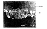
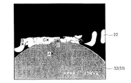
- 238000001878 scanning electron micrograph Methods 0.000 description 4
- VYZAMTAEIAYCRO-UHFFFAOYSA-N Chromium Chemical compound [Cr] VYZAMTAEIAYCRO-UHFFFAOYSA-N 0.000 description 3
- GRYLNZFGIOXLOG-UHFFFAOYSA-N Nitric acid Chemical compound O[N+]([O-])=O GRYLNZFGIOXLOG-UHFFFAOYSA-N 0.000 description 3
- 239000010953 base metal Substances 0.000 description 3
- 229910052804 chromium Inorganic materials 0.000 description 3
- 239000011651 chromium Substances 0.000 description 3
- 229910000856 hastalloy Inorganic materials 0.000 description 3
- 238000005259 measurement Methods 0.000 description 3
- 229910017604 nitric acid Inorganic materials 0.000 description 3
- CSCPPACGZOOCGX-UHFFFAOYSA-N Acetone Chemical compound CC(C)=O CSCPPACGZOOCGX-UHFFFAOYSA-N 0.000 description 2
- LFQSCWFLJHTTHZ-UHFFFAOYSA-N Ethanol Chemical compound CCO LFQSCWFLJHTTHZ-UHFFFAOYSA-N 0.000 description 2
- 229910021578 Iron(III) chloride Inorganic materials 0.000 description 2
- ZOKXTWBITQBERF-UHFFFAOYSA-N Molybdenum Chemical compound [Mo] ZOKXTWBITQBERF-UHFFFAOYSA-N 0.000 description 2
- ATUOYWHBWRKTHZ-UHFFFAOYSA-N Propane Chemical compound CCC ATUOYWHBWRKTHZ-UHFFFAOYSA-N 0.000 description 2
- 239000000919 ceramic Substances 0.000 description 2
- 239000003795 chemical substances by application Substances 0.000 description 2
- 230000007423 decrease Effects 0.000 description 2
- 239000001257 hydrogen Substances 0.000 description 2
- 229910052739 hydrogen Inorganic materials 0.000 description 2
- 238000007654 immersion Methods 0.000 description 2
- RBTARNINKXHZNM-UHFFFAOYSA-K iron trichloride Chemical compound Cl[Fe](Cl)Cl RBTARNINKXHZNM-UHFFFAOYSA-K 0.000 description 2
- 238000002844 melting Methods 0.000 description 2
- 230000008018 melting Effects 0.000 description 2
- 229910052750 molybdenum Inorganic materials 0.000 description 2
- 239000011733 molybdenum Substances 0.000 description 2
- 238000001228 spectrum Methods 0.000 description 2
- UGFAIRIUMAVXCW-UHFFFAOYSA-N Carbon monoxide Chemical compound [O+]#[C-] UGFAIRIUMAVXCW-UHFFFAOYSA-N 0.000 description 1
- 241000218645 Cedrus Species 0.000 description 1
- RYGMFSIKBFXOCR-UHFFFAOYSA-N Copper Chemical compound [Cu] RYGMFSIKBFXOCR-UHFFFAOYSA-N 0.000 description 1
- 229910000881 Cu alloy Inorganic materials 0.000 description 1
- VGGSQFUCUMXWEO-UHFFFAOYSA-N Ethene Chemical compound C=C VGGSQFUCUMXWEO-UHFFFAOYSA-N 0.000 description 1
- 239000005977 Ethylene Substances 0.000 description 1
- 229910001111 Fine metal Inorganic materials 0.000 description 1
- 229910000760 Hardened steel Inorganic materials 0.000 description 1
- 229910001182 Mo alloy Inorganic materials 0.000 description 1
- 229910000792 Monel Inorganic materials 0.000 description 1
- 229910001252 Pd alloy Inorganic materials 0.000 description 1
- 229910000629 Rh alloy Inorganic materials 0.000 description 1
- -1 SUS316L Substances 0.000 description 1
- 229910001069 Ti alloy Inorganic materials 0.000 description 1
- RTAQQCXQSZGOHL-UHFFFAOYSA-N Titanium Chemical compound [Ti] RTAQQCXQSZGOHL-UHFFFAOYSA-N 0.000 description 1
- 229910052782 aluminium Inorganic materials 0.000 description 1
- XAGFODPZIPBFFR-UHFFFAOYSA-N aluminium Chemical compound [Al] XAGFODPZIPBFFR-UHFFFAOYSA-N 0.000 description 1
- PNEYBMLMFCGWSK-UHFFFAOYSA-N aluminium oxide Inorganic materials [O-2].[O-2].[O-2].[Al+3].[Al+3] PNEYBMLMFCGWSK-UHFFFAOYSA-N 0.000 description 1
- 239000001273 butane Substances 0.000 description 1
- 229910002091 carbon monoxide Inorganic materials 0.000 description 1
- 238000006243 chemical reaction Methods 0.000 description 1
- OGSYQYXYGXIQFH-UHFFFAOYSA-N chromium molybdenum nickel Chemical compound [Cr].[Ni].[Mo] OGSYQYXYGXIQFH-UHFFFAOYSA-N 0.000 description 1
- 239000004020 conductor Substances 0.000 description 1
- 229910052802 copper Inorganic materials 0.000 description 1
- 239000010949 copper Substances 0.000 description 1
- YOCUPQPZWBBYIX-UHFFFAOYSA-N copper nickel Chemical compound [Ni].[Cu] YOCUPQPZWBBYIX-UHFFFAOYSA-N 0.000 description 1
- 238000005260 corrosion Methods 0.000 description 1
- 230000007797 corrosion Effects 0.000 description 1
- 238000002474 experimental method Methods 0.000 description 1
- 238000010304 firing Methods 0.000 description 1
- 239000000446 fuel Substances 0.000 description 1
- 238000010438 heat treatment Methods 0.000 description 1
- 230000006872 improvement Effects 0.000 description 1
- 229910001026 inconel Inorganic materials 0.000 description 1
- SORXVYYPMXPIFD-UHFFFAOYSA-N iron palladium Chemical compound [Fe].[Pd] SORXVYYPMXPIFD-UHFFFAOYSA-N 0.000 description 1
- 239000003915 liquefied petroleum gas Substances 0.000 description 1
- 229910044991 metal oxide Inorganic materials 0.000 description 1
- 150000004706 metal oxides Chemical class 0.000 description 1
- 239000000203 mixture Substances 0.000 description 1
- 238000012986 modification Methods 0.000 description 1
- 230000004048 modification Effects 0.000 description 1
- IJDNQMDRQITEOD-UHFFFAOYSA-N n-butane Chemical compound CCCC IJDNQMDRQITEOD-UHFFFAOYSA-N 0.000 description 1
- OFBQJSOFQDEBGM-UHFFFAOYSA-N n-pentane Natural products CCCCC OFBQJSOFQDEBGM-UHFFFAOYSA-N 0.000 description 1
- 239000003960 organic solvent Substances 0.000 description 1
- TWNQGVIAIRXVLR-UHFFFAOYSA-N oxo(oxoalumanyloxy)alumane Chemical compound O=[Al]O[Al]=O TWNQGVIAIRXVLR-UHFFFAOYSA-N 0.000 description 1
- 238000012545 processing Methods 0.000 description 1
- 239000001294 propane Substances 0.000 description 1
- 239000011347 resin Substances 0.000 description 1
- 229920005989 resin Polymers 0.000 description 1
- 239000002002 slurry Substances 0.000 description 1
- 229910001256 stainless steel alloy Inorganic materials 0.000 description 1
- 239000010936 titanium Substances 0.000 description 1
- 229910052719 titanium Inorganic materials 0.000 description 1
- XLYOFNOQVPJJNP-UHFFFAOYSA-N water Substances O XLYOFNOQVPJJNP-UHFFFAOYSA-N 0.000 description 1
- 238000001039 wet etching Methods 0.000 description 1
Images


Classifications
-
- H—ELECTRICITY
- H05—ELECTRIC TECHNIQUES NOT OTHERWISE PROVIDED FOR
- H05B—ELECTRIC HEATING; ELECTRIC LIGHT SOURCES NOT OTHERWISE PROVIDED FOR; CIRCUIT ARRANGEMENTS FOR ELECTRIC LIGHT SOURCES, IN GENERAL
- H05B3/00—Ohmic-resistance heating
- H05B3/10—Heating elements characterised by the composition or nature of the materials or by the arrangement of the conductor
- H05B3/18—Heating elements characterised by the composition or nature of the materials or by the arrangement of the conductor the conductor being embedded in an insulating material
-
- G—PHYSICS
- G01—MEASURING; TESTING
- G01N—INVESTIGATING OR ANALYSING MATERIALS BY DETERMINING THEIR CHEMICAL OR PHYSICAL PROPERTIES
- G01N27/00—Investigating or analysing materials by the use of electric, electrochemical, or magnetic means
- G01N27/02—Investigating or analysing materials by the use of electric, electrochemical, or magnetic means by investigating impedance
- G01N27/04—Investigating or analysing materials by the use of electric, electrochemical, or magnetic means by investigating impedance by investigating resistance
- G01N27/14—Investigating or analysing materials by the use of electric, electrochemical, or magnetic means by investigating impedance by investigating resistance of an electrically-heated body in dependence upon change of temperature
- G01N27/16—Investigating or analysing materials by the use of electric, electrochemical, or magnetic means by investigating impedance by investigating resistance of an electrically-heated body in dependence upon change of temperature caused by burning or catalytic oxidation of surrounding material to be tested, e.g. of gas
-
- G—PHYSICS
- G01—MEASURING; TESTING
- G01N—INVESTIGATING OR ANALYSING MATERIALS BY DETERMINING THEIR CHEMICAL OR PHYSICAL PROPERTIES
- G01N27/00—Investigating or analysing materials by the use of electric, electrochemical, or magnetic means
- G01N27/02—Investigating or analysing materials by the use of electric, electrochemical, or magnetic means by investigating impedance
- G01N27/04—Investigating or analysing materials by the use of electric, electrochemical, or magnetic means by investigating impedance by investigating resistance
- G01N27/14—Investigating or analysing materials by the use of electric, electrochemical, or magnetic means by investigating impedance by investigating resistance of an electrically-heated body in dependence upon change of temperature
Landscapes
- Chemical & Material Sciences (AREA)
- Chemical Kinetics & Catalysis (AREA)
- Electrochemistry (AREA)
- Physics & Mathematics (AREA)
- Health & Medical Sciences (AREA)
- Life Sciences & Earth Sciences (AREA)
- Analytical Chemistry (AREA)
- Biochemistry (AREA)
- General Health & Medical Sciences (AREA)
- General Physics & Mathematics (AREA)
- Immunology (AREA)
- Pathology (AREA)
- Investigating Or Analyzing Materials By The Use Of Electric Means (AREA)
Description
本発明は、ガスセンサ用ヒータコイル、ガスセンサ用検知素子、接触燃焼式ガスセンサおよび接触燃焼式ガスセンサの製造方法に関するものである。 The present invention relates to a heater coil for a gas sensor, a sensing element for a gas sensor, a catalytic combustion type gas sensor, and a method for manufacturing a catalytic combustion type gas sensor.
従来より、水素ガスやメタンガス等の可燃性ガスを検知するセンサとして、接触燃焼式ガスセンサが公知である。接触燃焼式ガスセンサは、ヒータコイルを被う熱伝導層に触媒層を担持させた検知素子を所定の温度に加熱しておき、可燃性ガスを触媒層に接触させて燃焼させ、その燃焼熱による温度変化に基づくヒータコイルの抵抗変化を電圧変化として出力することにより、可燃性ガスの存在を検知するものである。 Conventionally, a catalytic combustion type gas sensor is known as a sensor for detecting a combustible gas such as hydrogen gas or methane gas. The contact combustion type gas sensor heats a detection element, in which a catalyst layer is supported on a heat conductive layer covering a heater coil, to a predetermined temperature, causes a combustible gas to come into contact with the catalyst layer, and burns it. The presence of the combustible gas is detected by outputting the resistance change of the heater coil based on the temperature change as a voltage change.
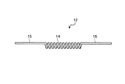
図18は、従来の検知素子の構成を示す断面図であり、図19は、従来のヒータコイルの構成を示す正面図である。図18に示すように、従来の検知素子1は、熱伝導層11中にヒータコイル12が埋め込まれており、熱伝導層11の表面に触媒層13が付着された構成となっている。図19に示すように、従来のヒータコイル12では、熱伝導層11中に埋め込まれる部分(以下、ビード部とする)は、線材をコイル状に巻いた一重巻回コイルとなっている(例えば、特許文献1参照。)。ビード部14の両端から伸びるリード部15は、コイル状になっていない。なお、本明細書では、検知素子において、ヒータコイルのビード部を熱伝導層および触媒層が被う部分を、燃焼部と呼ぶことにする。
FIG. 18 is a cross-sectional view showing the configuration of a conventional sensing element, and FIG. 19 is a front view showing the configuration of a conventional heater coil. As shown in FIG. 18, the conventional sensing element 1 has a configuration in which a
また、接触燃焼式ガスセンサでは、上述した構成の検知素子と、この検知素子と同様の構成で、かつ触媒の代わりに不活性な酸化物を担持させた補償素子と、2個の抵抗素子とにより、ホイートストンブリッジ回路が構成されている。そして、燃焼熱によりヒータコイルの抵抗が変化すると、その抵抗変化は、ホイートストンブリッジ回路から電圧変化として出力される(例えば、特許文献2参照。)。 Further, in the contact combustion type gas sensor, the detection element having the above-described configuration, a compensation element having the same configuration as the detection element and carrying an inert oxide instead of the catalyst, and two resistance elements are included. The Wheatstone bridge circuit is configured. And if resistance of a heater coil changes with combustion heat, the resistance change will be outputted as a voltage change from a Wheatstone bridge circuit (for example, refer to patent documents 2).
検知素子を作製する方法として、芯線に抵抗線を巻回し、その状態で絶縁剤を電着コートし、絶縁剤を加熱焼成した後、抵抗線の非有効部分を露出させ、芯線を溶解してから、電極ピンに溶接する方法が公知である(例えば、特許文献3参照。)。この方法によれば、検知素子を製造する際に、抵抗線の巻回部の形状が崩れるのを防ぐことができる。 As a method for producing a sensing element, a resistance wire is wound around a core wire, and an insulating agent is electrodeposited and coated in that state. After heating and firing the insulating agent, an ineffective portion of the resistance wire is exposed, and the core wire is dissolved. Therefore, a method of welding to an electrode pin is known (for example, see Patent Document 3). According to this method, it is possible to prevent the shape of the winding portion of the resistance wire from collapsing when the sensing element is manufactured.
接触燃焼式ガスセンサでは、同じガス濃度であれば、ホイートストンブリッジ回路から出力される電圧の変化量は大きい方が好ましい。この出力電圧の変化量が大きいということは、ガス感度が高いということである。ヒータコイルのビード部のコイル巻き数を増やせば、ヒータコイルの、燃焼熱による抵抗変化に寄与する部分の長さ(以下、有効長とする)が長くなり、ヒータコイルの抵抗が大きくなるので、ガス感度が高くなる。 In the contact combustion type gas sensor, it is preferable that the change amount of the voltage output from the Wheatstone bridge circuit is large if the gas concentration is the same. A large change in the output voltage means high gas sensitivity. If the number of coil turns in the bead portion of the heater coil is increased, the length of the heater coil contributing to the resistance change due to combustion heat (hereinafter referred to as the effective length) is increased, and the resistance of the heater coil is increased. Increases gas sensitivity.
また、接触燃焼式ガスセンサでは、同じガス濃度であれば、ホイートストンブリッジ回路から出力される電圧ができるだけ短時間で安定する方が好ましい。出力電圧の安定に要する時間が短いということは、応答速度が速いということである。応答速度を速くするには、燃焼部内にヒータコイルの線材をできるだけ長く埋め込み、ヒータコイルが燃焼熱を効率よく受けて、ヒータコイルの抵抗変化が効率よく起こるようにすればよい。 Further, in the contact combustion type gas sensor, it is preferable that the voltage output from the Wheatstone bridge circuit is stabilized in a short time as long as the gas concentration is the same. The short time required to stabilize the output voltage means that the response speed is fast. In order to increase the response speed, it is only necessary to embed the heater coil wire as long as possible in the combustion section so that the heater coil receives the combustion heat efficiently and the resistance change of the heater coil occurs efficiently.
しかし、いずれの場合も、ヒータコイルのビード部が大きくなり、それに伴ってビード部を覆う熱伝導層の量や触媒層の量も増えるので、燃焼部が重くなってしまう。検知素子は、ヒータコイルの両端のリード部を外部接続用の電極ピンで支持することにより、センサ内に取り付けられているので、燃焼部が重くなると、リード部で検知素子を支えきれなくなり、リード部の破断などの故障が起こりやすくなる。 However, in either case, the bead portion of the heater coil is increased, and accordingly, the amount of the heat conductive layer and the amount of the catalyst layer covering the bead portion are increased, so that the combustion portion becomes heavy. The detection element is mounted in the sensor by supporting the lead parts at both ends of the heater coil with electrode pins for external connection. Therefore, if the combustion part becomes heavy, the detection part cannot be supported by the lead part. Failure such as breakage of parts tends to occur.
従って、従来の接触燃焼式ガスセンサでは、ヒータコイルのリード部での検知素子の支持能力を犠牲にすることなく、ガス感度の向上および応答速度の高速化を図ることは極めて困難である。また、従来の接触燃焼式ガスセンサでは、ヒータコイルのリード部に衝撃吸収能力がないため、外部から衝撃が加わると、その衝撃が殆ど緩和されずに燃焼部に集中してしまう。そのため、触媒層の欠落などが発生しやすいという不具合があり、調整済みのゼロ点が大きく変動してしまうという欠点がある。 Therefore, in the conventional catalytic combustion type gas sensor, it is extremely difficult to improve the gas sensitivity and increase the response speed without sacrificing the support capability of the sensing element at the lead portion of the heater coil. Further, in the conventional catalytic combustion type gas sensor, since the lead part of the heater coil does not have an impact absorbing capability, when an impact is applied from the outside, the impact is hardly relaxed and concentrated on the combustion part. Therefore, there is a problem that the catalyst layer is likely to be lost, and the adjusted zero point is greatly fluctuated.
そこで、本発明者らは、燃焼部に埋め込まれる部分だけをコイル状にした従来のヒータコイルに代えて、線材をコイル状に巻いたコイル線の一部をさらにコイル状に巻いたコイルドコイルをヒータコイルとして用いることを提案する。この提案によれば、従来のヒータコイルと外観上の寸法が同じでも、ヒータコイルを構成する線材の実際の長さが従来よりも長くなるので、ヒータコイルの抵抗が大きくなり、ガス感度が高くなる。また、ヒータコイルのコイルドコイルの部分が燃焼部内に埋め込まれることによって、燃焼部内の線材の長さが従来よりも長くなるので、ヒータコイルの抵抗変化が効率よく起こり、応答速度が速くなる。 Therefore, the present inventors have replaced a conventional heater coil in which only the portion embedded in the combustion section is coiled with a coiled coil in which a part of a coil wire wound in a coil shape is further wound in a coil shape. Proposed to use as a coil. According to this proposal, even if the external dimensions of the conventional heater coil are the same, the actual length of the wire constituting the heater coil is longer than that of the conventional heater coil, so that the resistance of the heater coil is increased and the gas sensitivity is increased. Become. In addition, since the coiled coil portion of the heater coil is embedded in the combustion portion, the length of the wire in the combustion portion becomes longer than before, so that the resistance change of the heater coil occurs efficiently and the response speed increases.
しかしながら、コイルドコイルよりなるヒータコイルでは、電極ピンに溶接される部分がすでにコイル状になっているため、上記特許文献3に開示されているように芯線を溶解してから溶接を行う方法では、次のような新たな問題が生じることがわかった。例えば、芯線の溶解後にヒータコイルを取り扱う際にコイルの巻回部を不用意に潰してしまうことが多い。また、溶接時に溶接部位でヒータコイルの巻回部が不規則に潰れたり、コイル形状が歪んでヒータコイルが部分的に短絡してしまうため、ロット内におけるヒータコイルの抵抗値のばらつきが大きい。さらに、芯線を溶解させたことにより、その芯線のあった部分、すなわちコイルの内側部分が空胴になっているため、溶接自体が不安定となり、十分な接合強度が得られない。
However, in the heater coil made of a coiled coil, the portion welded to the electrode pin is already coiled. Therefore, as disclosed in
本発明は、上記に鑑みてなされたものであって、ヒータコイルのリード部での検知素子の支持能力を犠牲にすることなく、ガス感度の向上を図ることができるガスセンサ用ヒータコイル、ガスセンサ用検知素子および接触燃焼式ガスセンサを提供すること、またはヒータコイルのリード部での検知素子の支持能力を犠牲にすることなく、応答速度の高速化を図ることができるガスセンサ用ヒータコイル、ガスセンサ用検知素子および接触燃焼式ガスセンサを提供することを目的とする。また、本発明は、衝撃が加わった場合のゼロ点の変動量を小さくすることができるガスセンサ用ヒータコイル、ガスセンサ用検知素子および接触燃焼式ガスセンサを提供することを目的とする。 The present invention has been made in view of the above, and a heater coil for a gas sensor and a gas sensor that can improve gas sensitivity without sacrificing the support capability of the sensing element at the lead portion of the heater coil. Providing a sensing element and a catalytic combustion type gas sensor, or a heater coil for a gas sensor and a sensing for a gas sensor capable of increasing the response speed without sacrificing the support capability of the sensing element at the lead portion of the heater coil An object is to provide an element and a catalytic combustion type gas sensor. Another object of the present invention is to provide a heater coil for a gas sensor, a detection element for a gas sensor, and a contact combustion type gas sensor that can reduce the fluctuation amount of the zero point when an impact is applied.
また、本発明は、少なくとも両端がコイル状に巻かれたヒータコイルの巻回部の形状を崩すことなく、ヒータコイルを容易に取り扱うことができる接触燃焼式ガスセンサの製造方法を提供することを目的とする。また、本発明は、少なくとも両端がコイル状に巻かれたヒータコイルの抵抗値のばらつきを小さくすることができる接触燃焼式ガスセンサの製造方法を提供することを目的とする。さらに、本発明は、少なくとも両端がコイル状に巻かれたヒータコイルと電極ピンとの接合強度を高くすることができる接触燃焼式ガスセンサの製造方法を提供することを目的とする。 Another object of the present invention is to provide a method for manufacturing a contact combustion type gas sensor that can easily handle a heater coil without breaking the shape of the winding portion of the heater coil wound at least at both ends in a coil shape. And It is another object of the present invention to provide a method for manufacturing a contact combustion type gas sensor that can reduce variations in resistance value of a heater coil wound at least at both ends in a coil shape. Furthermore, an object of the present invention is to provide a method for manufacturing a contact combustion type gas sensor capable of increasing the bonding strength between a heater coil and an electrode pin wound at least at both ends in a coil shape.
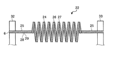
上述した課題を解決し、目的を達成するため、この発明にかかるガスセンサ用ヒータコイルは、接触燃焼式ガスセンサに用いられるヒータコイルであって、ガスの燃焼時に発生する燃焼熱により電気的な特性値が変化するビード部と、該ビード部の両端から伸びるリード部とを有し、2以上の整数nに対して、前記ビード部が、コイル状に巻かれた(n−1)重巻回コイルよりなる素線をさらにコイル状に巻いたn重巻回コイルにより構成されていることを特徴とする。 In order to solve the above-described problems and achieve the object, a heater coil for a gas sensor according to the present invention is a heater coil used in a catalytic combustion type gas sensor, and has an electrical characteristic value due to combustion heat generated during combustion of gas. (N-1) multi-turn coil in which the bead portion has a bead portion that changes and lead portions extending from both ends of the bead portion, and the bead portion is wound in a coil shape with respect to an integer n of 2 or more It is characterized by being comprised by the n times wound coil which wound the element wire which consists of further in the shape of a coil.
この発明によれば、このヒータコイルを用いて検知素子を作製することによって、検知素子の燃焼部の大きさが従来とほぼ同じであっても、燃焼部内に埋め込まれるビード部の有効長が、ビード部を従来の一重巻回コイルで構成した場合よりも長くなる。従って、ヒータコイルの抵抗が大きくなるので、このヒータコイルを用いた接触燃焼式ガスセンサでは、ガス感度が高くなる。また、ヒータコイルがより多くの燃焼熱を受けて、効率よく抵抗変化を起こすので、このヒータコイルを用いた接触燃焼式ガスセンサでは、応答速度が速くなる。さらに、燃焼部の大きさは従来とほぼ同じでよいので、燃焼部の重さも従来とほぼ同じになる。従って、このヒータコイルを用いることによって、リード部での検知素子の支持能力を犠牲にすることなく、接触燃焼式ガスセンサのガス感度の向上や応答速度の高速化を図ることができる。 According to this invention, by producing a sensing element using this heater coil, even if the size of the combustion part of the sensing element is substantially the same as the conventional, the effective length of the bead part embedded in the combustion part is The bead portion is longer than the conventional single-winding coil. Therefore, since the resistance of the heater coil is increased, the gas sensitivity is increased in the contact combustion type gas sensor using the heater coil. In addition, since the heater coil receives more combustion heat and efficiently changes the resistance, the contact combustion type gas sensor using this heater coil has a high response speed. Further, since the size of the combustion part may be substantially the same as the conventional one, the weight of the combustion part is also substantially the same as the conventional one. Therefore, by using this heater coil, it is possible to improve the gas sensitivity of the catalytic combustion type gas sensor and increase the response speed without sacrificing the support capability of the detection element at the lead portion.
この発明にかかるガスセンサ用ヒータコイルは、上記に記載の発明において、前記リード部が、(n−1)重巻回コイルにより構成されていることを特徴とする。 The heater coil for a gas sensor according to the present invention is characterized in that, in the above-described invention, the lead portion is constituted by an (n-1) multi-turn coil.
この発明によれば、リード部がコイルばねと同様の構成になっているので、このヒータコイルを用いた接触燃焼式ガスセンサでは、外部から加わった衝撃がリード部のばね弾性により吸収される。従って、燃焼部に伝わる衝撃が小さくなるので、触媒層の欠落などが発生しにくくなり、接触燃焼式ガスセンサのゼロ点が衝撃により大きく変動するのを抑えることができる。 According to the present invention, since the lead portion has the same configuration as the coil spring, in the contact combustion type gas sensor using this heater coil, the impact applied from the outside is absorbed by the spring elasticity of the lead portion. Therefore, since the impact transmitted to the combustion portion is reduced, it is difficult for the catalyst layer to be lost and the zero point of the catalytic combustion type gas sensor can be prevented from greatly fluctuating due to the impact.
この発明にかかるガスセンサ用ヒータコイルは、上記に記載の発明において、出発材料となる非コイル状の原線の線径は、1μm以上100μm以下であることを特徴とする。 The heater coil for a gas sensor according to the present invention is characterized in that, in the above-described invention, the wire diameter of a non-coiled original wire that is a starting material is 1 μm or more and 100 μm or less.
この発明によれば、原線の線径が1μm以上であるので、ビード部が多重巻回コイルよりなるヒータコイルの作製が容易である。また、原線の線径が100μm以下であるので、このヒータコイルを用いることによって、接触燃焼式ガスセンサに用いるのに適した大きさの検知素子が得られる。 According to this invention, since the wire diameter of the original wire is 1 μm or more, it is easy to manufacture a heater coil whose bead portion is a multi-turn coil. Further, since the wire diameter of the original wire is 100 μm or less, a sensing element having a size suitable for use in a catalytic combustion type gas sensor can be obtained by using this heater coil.
この発明にかかるガスセンサ用ヒータコイルは、上記に記載の発明において、出発材料となる非コイル状の原線の線径は、10μm以上50μm以下であることを特徴とする。 The heater coil for a gas sensor according to the present invention is characterized in that, in the above-described invention, a wire diameter of a non-coiled original wire that is a starting material is 10 μm or more and 50 μm or less.
この発明によれば、このヒータコイルを用いることによって、接触燃焼式ガスセンサの制御回路を駆動する電源回路として、適当な電圧−電流値を有する電源回路を用いることができる。適当な電源回路を用いることは、接触燃焼式ガスセンサを動作させる際に、触媒層を適切な動作温度にすることができるので、重要である。 According to the present invention, by using this heater coil, a power supply circuit having an appropriate voltage-current value can be used as a power supply circuit for driving the control circuit of the catalytic combustion type gas sensor. Use of an appropriate power supply circuit is important because the catalyst layer can be brought to an appropriate operating temperature when the catalytic combustion type gas sensor is operated.
この発明にかかるガスセンサ用ヒータコイルは、上記に記載の発明において、出発材料となる非コイル状の原線の線径は、20μm以上30μm以下であることを特徴とする。 The heater coil for a gas sensor according to the present invention is characterized in that, in the above-described invention, a wire diameter of a non-coiled original wire as a starting material is 20 μm or more and 30 μm or less.
この発明によれば、このヒータコイルを用いることによって、燃焼部の重量が1mg程度の検知素子が得られるので、ヒータコイルのリード部で検知素子を十分に支えることができる。また、このヒータコイルを用いた接触燃焼式ガスセンサでは、耐衝撃強度も向上する。さらに、このヒータコイルを用いることによって、検知素子の燃焼部内にヒータコイルのビード部がより高密度に埋め込まれるので、ヒータコイルがより多くの燃焼熱を受けることができる。それによって、ヒータコイルの抵抗変化がより一層、効率よく起こる。従って、このヒータコイルを用いた接触燃焼式ガスセンサでは、応答速度がさらに速くなる。また、ヒータコイルの抵抗がより一層、大きくなるので、電源電圧をより高くすることができる。従って、このヒータコイルを用いた接触燃焼式ガスセンサでは、ガス感度がさらに高くなる。 According to the present invention, by using this heater coil, a sensing element having a combustion part weight of about 1 mg can be obtained, so that the sensing element can be sufficiently supported by the lead part of the heater coil. Further, in the contact combustion type gas sensor using the heater coil, the impact resistance strength is also improved. Furthermore, by using this heater coil, the bead portion of the heater coil is embedded at a higher density in the combustion portion of the detection element, so that the heater coil can receive more combustion heat. Thereby, the resistance change of the heater coil occurs more efficiently. Therefore, in the contact combustion type gas sensor using this heater coil, the response speed is further increased. Moreover, since the resistance of the heater coil is further increased, the power supply voltage can be further increased. Therefore, in the contact combustion type gas sensor using this heater coil, the gas sensitivity is further increased.
また、原線の線径が20μmよりも小さくなると、ヒータコイルを作製する際の歩留まりが低下するが、原線の線径が20μm以上であるので、ヒータコイルを容易に作製することができる。つまり、歩留まりを低下させることなく、ヒータコイルを作製することができ、またそのヒータコイルを用いることにより、接触燃焼式ガスセンサのガス感度および応答特性をさらに改善することができる。以上より、接触燃焼式ガスセンサのガス感度および応答特性と、ヒータコイルの作製の容易さとの兼ね合いを考慮すると、原線の線径は、20μm以上30μm以下であるのが最適である。 Further, if the wire diameter of the original wire is smaller than 20 μm, the yield when the heater coil is manufactured is reduced, but since the wire diameter of the original wire is 20 μm or more, the heater coil can be easily manufactured. That is, a heater coil can be produced without reducing the yield, and by using the heater coil, the gas sensitivity and response characteristics of the catalytic combustion type gas sensor can be further improved. From the above, considering the balance between the gas sensitivity and response characteristics of the contact combustion type gas sensor and the ease of production of the heater coil, the wire diameter of the original wire is optimally 20 μm or more and 30 μm or less.
この発明にかかるガスセンサ用ヒータコイルは、上記に記載の発明において、1以上n以下の整数mに対して、m重巻回コイルの巻き径は、m重巻回コイルを作製する際にコイル状に巻くために用いられる芯金の径の0.5倍以上20倍以下であることを特徴とする。 The heater coil for a gas sensor according to the present invention is the above described invention, wherein the winding diameter of the m-fold winding coil is coiled when the m-fold winding coil is manufactured for an integer m of 1 to n. It is characterized by being 0.5 to 20 times the diameter of the core bar used for winding.
この発明によれば、このヒータコイルを用いることによって、検知素子の燃焼部が重くならないので、ヒータコイルのリード部で検知素子を十分に支えることができる。それに対して、m重巻回コイルの巻き径が芯金の径の20倍を超えるヒータコイルを用いた場合には、ビード部のコイルの内側空間に充填される熱伝導層の量が増え、燃焼部が重くなるため、リード部による検知素子の支持性能が低下し、接触燃焼式ガスセンサの耐衝撃性能が実用上許容される範囲よりも低下することがあるという不都合が生じる。 According to the present invention, by using this heater coil, the detection element can be sufficiently supported by the lead portion of the heater coil because the burning part of the detection element does not become heavy. On the other hand, when using a heater coil in which the winding diameter of the m-fold winding coil exceeds 20 times the diameter of the cored bar, the amount of the heat conductive layer filled in the inner space of the coil of the bead portion increases. Since the combustion part becomes heavy, the support performance of the detection element by the lead part is lowered, and there is a disadvantage that the impact resistance performance of the contact combustion type gas sensor may be lower than the practically allowable range.
この発明にかかるガスセンサ用ヒータコイルは、上記に記載の発明において、1以上n以下の整数mに対して、m重巻回コイルの巻き径は、m重巻回コイルを作製する際にコイル状に巻くために用いられる芯金の径の1倍以上10倍以下であることを特徴とする。 The heater coil for a gas sensor according to the present invention is the above described invention, wherein the winding diameter of the m-fold winding coil is coiled when the m-fold winding coil is manufactured for an integer m of 1 to n. It is characterized in that it is 1 to 10 times the diameter of the core bar used for winding.
この発明によれば、巻線加工後のm重巻回コイルの形状安定性がよいので、ヒータコイルが歩留まりよく得られる。また、リード部による検知素子の支持性能が安定して得られる。なお、m重巻回コイルの巻き径が芯金の径の20倍以下であっても、10倍を超えると、巻線加工後のm重巻回コイルの形状安定性は、多少、低くなる。 According to this invention, since the shape stability of the m-fold winding coil after winding is good, the heater coil can be obtained with a high yield. Moreover, the support performance of the detection element by the lead portion can be obtained stably. In addition, even if the winding diameter of the m-fold winding coil is 20 times or less than the diameter of the core bar, if it exceeds 10 times, the shape stability of the m-fold winding coil after the winding process is somewhat lowered. .
この発明にかかるガスセンサ用ヒータコイルは、上記に記載の発明において、前記n重巻回コイルの巻き数は、1以上30以下であることを特徴とする。 The heater coil for a gas sensor according to the present invention is characterized in that, in the invention described above, the number of turns of the n-fold winding coil is 1 or more and 30 or less.
この発明によれば、このヒータコイルを用いることによって、検知素子の燃焼部が重くならないので、ヒータコイルのリード部で検知素子を十分に支えることができる。n重巻回コイルの巻き数が30を超えるヒータコイルを用いた場合には、燃焼部が重くなり、ヒータコイルのリード部で検知素子を安定して支えることができない。 According to the present invention, by using this heater coil, the detection element can be sufficiently supported by the lead portion of the heater coil because the burning part of the detection element does not become heavy. When a heater coil having n turns of more than 30 is used, the combustion part becomes heavy, and the detection element cannot be stably supported by the lead part of the heater coil.
この発明にかかるガスセンサ用ヒータコイルは、上記に記載の発明において、1以上の整数kに対して、前記n重巻回コイルにおけるk巻き目の巻回部と(k+1)巻き目の巻回部との間の隙間の長さは、前記(n−1)重巻回コイルよりなる素線の直径の0.5倍以上10倍以下であることを特徴とする。 The heater coil for a gas sensor according to the present invention is the above-described invention, wherein the winding portion of the kth winding and the winding portion of the (k + 1) th winding in the n-fold winding coil with respect to the integer k of 1 or more. The length of the gap between the coil and the coil is 0.5 to 10 times the diameter of the wire composed of the (n-1) multi-turn coil.
この発明によれば、このヒータコイルを用いた接触燃焼式ガスセンサでは、十分に高速な応答特性が得られる。また、このヒータコイルを用いて検知素子を作製する際に、n重巻回コイルにおけるk巻き目の巻回部と(k+1)巻き目の巻回部とが短絡するのを防ぐことができるとともに、ビード部のコイルの内側空間に熱伝導層を充填させて触媒層を形成することができる。それに対して、k巻き目の巻回部と(k+1)巻き目の巻回部との間の隙間が素線の直径の0.5倍の長さよりも短いヒータコイルでは、隣り合う巻回部同士が接触して短絡してしまうことがある。一方、当該隙間が素線の直径の10倍を超える場合には、巻回部間の隙間があきすぎているため、ビード部のコイルの内側空間に熱伝導層を十分に充填させることができず、従って触媒層を形成することができない。 According to the present invention, the contact combustion type gas sensor using this heater coil can obtain sufficiently high-speed response characteristics. Moreover, when producing a detection element using this heater coil, it is possible to prevent a short circuit between the winding part of the k-th winding and the winding part of the (k + 1) -th winding in the n-fold winding coil. The catalyst layer can be formed by filling the space inside the coil of the bead portion with the heat conductive layer. On the other hand, in a heater coil in which the gap between the winding portion of the k-th winding and the winding portion of the (k + 1) -th winding is shorter than the length of 0.5 times the diameter of the strand, adjacent winding portions They may come into contact with each other and short circuit. On the other hand, when the gap exceeds 10 times the diameter of the strand, the gap between the winding portions is too large, so that the space inside the coil of the bead portion can be sufficiently filled with the heat conductive layer. Therefore, the catalyst layer cannot be formed.
この発明にかかるガスセンサ用ヒータコイルは、上記に記載の発明において、白金の線材でできていることを特徴とする。この発明にかかるガスセンサ用ヒータコイルは、上記に記載の発明において、白金をベースとする合金の線材でできていることを特徴とする。 The heater coil for a gas sensor according to the present invention is characterized by being made of platinum wire in the above-described invention. The heater coil for a gas sensor according to the present invention is characterized in that, in the above-described invention, the heater coil is made of a platinum-based alloy wire.
この発明にかかるガスセンサ用ヒータコイルは、接触燃焼式ガスセンサに用いられるヒータコイルであって、ガスの燃焼時に発生する燃焼熱により電気的な特性値が変化するビード部と、該ビード部の両端から伸びるリード部とを有し、前記リード部がコイル状に巻かれていることを特徴とする。 A heater coil for a gas sensor according to the present invention is a heater coil used in a contact combustion type gas sensor, and includes a bead portion whose electrical characteristic value is changed by combustion heat generated during gas combustion, and both ends of the bead portion. And a lead portion extending, and the lead portion is wound in a coil shape.
この発明によれば、リード部がコイルばねと同様の構成になっているので、このヒータコイルを用いた接触燃焼式ガスセンサでは、外部から加わった衝撃がリード部のばね弾性により吸収される。従って、検知素子の燃焼部に伝わる衝撃が小さくなるので、触媒層の欠落などが発生しにくくなり、接触燃焼式ガスセンサのゼロ点が衝撃により大きく変動するのを抑えることができる。 According to the present invention, since the lead portion has the same configuration as the coil spring, in the contact combustion type gas sensor using this heater coil, the impact applied from the outside is absorbed by the spring elasticity of the lead portion. Therefore, since the impact transmitted to the combustion part of the detection element is reduced, it is difficult for the catalyst layer to be lost and the zero point of the catalytic combustion type gas sensor can be prevented from greatly fluctuating due to the impact.
また、上述した課題を解決し、目的を達成するため、この発明にかかるガスセンサ用検知素子は、接触燃焼式ガスセンサに用いられる検知素子であって、ガスの燃焼時に発生する燃焼熱により電気的な特性値が変化するビード部、および該ビード部の両端から伸びるリード部を有するヒータコイルと、前記ビード部を覆う熱伝導層と、前記熱伝導層の表面に付着された触媒層と、を備え、2以上の整数nに対して、前記ビード部が、コイル状に巻かれた(n−1)重巻回コイルよりなる素線をさらにコイル状に巻いたn重巻回コイルにより構成されていることを特徴とする。 In order to solve the above-described problems and achieve the object, a gas sensor sensing element according to the present invention is a sensing element used in a catalytic combustion type gas sensor, and is electrically generated by combustion heat generated during gas combustion. A heater coil having a bead portion whose characteristic value changes, and a lead portion extending from both ends of the bead portion, a heat conductive layer covering the bead portion, and a catalyst layer attached to the surface of the heat conductive layer. For an integer n of 2 or more, the bead portion is constituted by an n-fold winding coil in which a wire made of a (n-1) multi-turn coil wound in a coil shape is further wound in a coil shape. It is characterized by being.
この発明によれば、検知素子の燃焼部の大きさが従来とほぼ同じであっても、燃焼部内に埋め込まれるビード部の有効長が、ビード部を従来の一重巻回コイルで構成した場合よりも長くなる。従って、ヒータコイルの抵抗が大きくなるので、この検知素子を用いた接触燃焼式ガスセンサでは、ガス感度が高くなる。また、ヒータコイルがより多くの燃焼熱を受けて、効率よく抵抗変化を起こすので、この検知素子を用いた接触燃焼式ガスセンサでは、応答速度が速くなる。さらに、燃焼部の大きさは従来とほぼ同じでよいので、燃焼部の重さも従来とほぼ同じになる。従って、リード部での検知素子の支持能力を犠牲にすることなく、接触燃焼式ガスセンサのガス感度の向上や応答速度の高速化を図ることができる。 According to the present invention, even if the size of the combustion portion of the detection element is substantially the same as that of the conventional case, the effective length of the bead portion embedded in the combustion portion is greater than that in the case where the bead portion is configured by a conventional single winding coil. Also gets longer. Therefore, since the resistance of the heater coil is increased, the gas sensitivity is increased in the contact combustion type gas sensor using this detection element. In addition, since the heater coil receives more combustion heat and efficiently changes the resistance, the contact combustion type gas sensor using this detection element has a high response speed. Further, since the size of the combustion part may be substantially the same as the conventional one, the weight of the combustion part is also substantially the same as the conventional one. Therefore, the gas sensitivity of the catalytic combustion type gas sensor can be improved and the response speed can be increased without sacrificing the support capability of the detection element at the lead portion.
この発明にかかるガスセンサ用検知素子は、上記に記載の発明において、前記ヒータコイルのリード部が、(n−1)重巻回コイルにより構成されていることを特徴とする。 The gas sensor sensing element according to the present invention is characterized in that, in the above-described invention, the lead portion of the heater coil is constituted by an (n-1) multi-turn coil.
この発明によれば、ヒータコイルのリード部がコイルばねと同様の構成になっているので、この検知素子を用いた接触燃焼式ガスセンサでは、外部から加わった衝撃がリード部のばね弾性により吸収される。従って、燃焼部に伝わる衝撃が小さくなるので、触媒層の欠落などが発生しにくくなり、接触燃焼式ガスセンサのゼロ点が衝撃により大きく変動するのを抑えることができる。 According to the present invention, since the lead portion of the heater coil has the same configuration as that of the coil spring, in the contact combustion type gas sensor using this detection element, the impact applied from the outside is absorbed by the spring elasticity of the lead portion. The Therefore, since the impact transmitted to the combustion portion is reduced, it is difficult for the catalyst layer to be lost and the zero point of the catalytic combustion type gas sensor can be prevented from greatly fluctuating due to the impact.
この発明にかかるガスセンサ用検知素子は、上記に記載の発明において、前記ヒータコイルの出発材料となる非コイル状の原線の線径は、1μm以上100μm以下であることを特徴とする。 The sensing element for a gas sensor according to the present invention is characterized in that, in the above-described invention, a wire diameter of a non-coiled original wire that is a starting material of the heater coil is 1 μm or more and 100 μm or less.
この発明によれば、ヒータコイルの原線の線径が1μm以上であるので、ビード部が多重巻回コイルよりなるヒータコイルを容易に作製することができる。従って、検知素子の作製が容易となる。また、ヒータコイルの原線の線径が100μm以下であるので、接触燃焼式ガスセンサに用いるのに適した大きさの検知素子が得られる。 According to this invention, since the wire diameter of the heater coil original wire is 1 μm or more, a heater coil having a bead portion formed of a multiple winding coil can be easily manufactured. Therefore, the detection element can be easily manufactured. Moreover, since the wire diameter of the heater coil is 100 μm or less, a detection element having a size suitable for use in a catalytic combustion type gas sensor can be obtained.
この発明にかかるガスセンサ用検知素子は、上記に記載の発明において、前記ヒータコイルの出発材料となる非コイル状の原線の線径は、10μm以上50μm以下であることを特徴とする。 The sensing element for a gas sensor according to the present invention is characterized in that, in the above-described invention, a wire diameter of a non-coiled original wire that is a starting material of the heater coil is 10 μm or more and 50 μm or less.
この発明によれば、この検知素子を用いることによって、接触燃焼式ガスセンサの制御回路を駆動する電源回路として、適当な電圧−電流値を有する電源回路を用いることができる。適当な電源回路を用いることは、接触燃焼式ガスセンサを動作させる際に、触媒層を適切な動作温度にすることができるので、重要である。 According to the present invention, by using this detection element, a power supply circuit having an appropriate voltage-current value can be used as a power supply circuit for driving the control circuit of the catalytic combustion type gas sensor. Use of an appropriate power supply circuit is important because the catalyst layer can be brought to an appropriate operating temperature when the catalytic combustion type gas sensor is operated.
この発明にかかるガスセンサ用検知素子は、上記に記載の発明において、前記ヒータコイルの出発材料となる非コイル状の原線の線径は、20μm以上30μm以下であることを特徴とする。 The gas sensor sensing element according to the present invention is characterized in that, in the above-described invention, a wire diameter of a non-coiled original wire which is a starting material of the heater coil is 20 μm or more and 30 μm or less.
この発明によれば、燃焼部の重量を1mg程度にすることができるので、ヒータコイルのリード部で検知素子を十分に支えることができる。また、この検知素子を用いた接触燃焼式ガスセンサでは、耐衝撃強度も向上する。さらに、燃焼部内にヒータコイルのビード部がより高密度に埋め込まれるので、ヒータコイルがより多くの燃焼熱を受けることができる。それによって、ヒータコイルの抵抗変化がより一層、効率よく起こる。従って、この検知素子を用いた接触燃焼式ガスセンサでは、応答速度がさらに速くなる。また、ヒータコイルの抵抗がより一層、大きくなるので、電源電圧をより高くすることができる。従って、この検知素子を用いた接触燃焼式ガスセンサでは、ガス感度がさらに高くなる。 According to this invention, since the weight of the combustion part can be about 1 mg, the detection element can be sufficiently supported by the lead part of the heater coil. Moreover, in the contact combustion type gas sensor using this detection element, the impact resistance strength is also improved. Furthermore, since the bead portion of the heater coil is embedded at a higher density in the combustion portion, the heater coil can receive more combustion heat. Thereby, the resistance change of the heater coil occurs more efficiently. Therefore, in the contact combustion type gas sensor using this detection element, the response speed is further increased. Moreover, since the resistance of the heater coil is further increased, the power supply voltage can be further increased. Therefore, in the contact combustion type gas sensor using this detection element, the gas sensitivity is further increased.
また、ヒータコイルの原線の線径が20μmよりも小さくなると、ヒータコイルを作製する際の歩留まりが低下するが、ヒータコイルの原線の線径が20μm以上であるので、ヒータコイルを容易に作製することができる。従って、歩留まりよく検知素子が得られる。つまり、歩留まりを低下させることなく、検知素子を作製することができ、またその作製した検知素子を用いることにより、接触燃焼式ガスセンサのガス感度および応答特性をさらに改善することができる。以上より、接触燃焼式ガスセンサのガス感度および応答特性と、ヒータコイルの作製の容易さとの兼ね合いを考慮すると、ヒータコイルの原線の線径は、20μm以上30μm以下であるのが最適である。 Further, if the wire diameter of the heater coil original wire is smaller than 20 μm, the yield when the heater coil is manufactured is reduced, but the heater coil original wire diameter is 20 μm or more, so that the heater coil can be easily formed. Can be produced. Therefore, a sensing element can be obtained with a high yield. That is, the sensing element can be produced without reducing the yield, and the gas sensitivity and response characteristics of the catalytic combustion type gas sensor can be further improved by using the produced sensing element. From the above, considering the balance between the gas sensitivity and response characteristics of the contact combustion type gas sensor and the ease of production of the heater coil, it is optimal that the wire diameter of the heater coil is 20 μm or more and 30 μm or less.
この発明にかかるガスセンサ用検知素子は、上記に記載の発明において、1以上n以下の整数mに対して、前記ヒータコイルのm重巻回コイルの巻き径は、m重巻回コイルを作製する際にコイル状に巻くために用いられる芯金の径の0.5倍以上20倍以下であることを特徴とする。 The sensing element for a gas sensor according to the present invention is the above-described invention, wherein the winding diameter of the m-fold winding coil of the heater coil is an m-fold winding coil with respect to an integer m of 1 to n. In this case, the diameter is 0.5 to 20 times the diameter of the core used for winding in a coil shape.
この発明によれば、燃焼部が重くならないので、ヒータコイルのリード部で検知素子を十分に支えることができる。それに対して、m重巻回コイルの巻き径が芯金の径の20倍を超えるヒータコイルを用いた場合には、ビード部のコイルの内側空間に充填される熱伝導層の量が増え、燃焼部が重くなるため、リード部による検知素子の支持性能が低下し、接触燃焼式ガスセンサの耐衝撃性能が実用上許容される範囲よりも低下することがあるという不都合が生じる。 According to this invention, since the combustion part does not become heavy, the detection element can be sufficiently supported by the lead part of the heater coil. On the other hand, when using a heater coil in which the winding diameter of the m-fold winding coil exceeds 20 times the diameter of the cored bar, the amount of the heat conductive layer filled in the inner space of the coil of the bead portion increases. Since the combustion part becomes heavy, the support performance of the detection element by the lead part is lowered, and there is a disadvantage that the impact resistance performance of the contact combustion type gas sensor may be lower than the practically allowable range.
この発明にかかるガスセンサ用検知素子は、上記に記載の発明において、1以上n以下の整数mに対して、前記ヒータコイルのm重巻回コイルの巻き径は、m重巻回コイルを作製する際にコイル状に巻くために用いられる芯金の径の1倍以上10倍以下であることを特徴とする。 The sensing element for a gas sensor according to the present invention is the above-described invention, wherein the winding diameter of the m-fold winding coil of the heater coil is an m-fold winding coil with respect to an integer m of 1 to n. It is characterized in that it is 1 to 10 times the diameter of the core used for winding in a coil.
この発明によれば、ヒータコイルを作製する際に、巻線加工後のm重巻回コイルの形状安定性がよいので、歩留まりよくヒータコイルが得られる。従って、歩留まりよく検知素子が得られる。また、リード部による検知素子の支持性能が安定して得られる。なお、m重巻回コイルの巻き径が芯金の径の20倍以下であっても、10倍を超えると、巻線加工後のm重巻回コイルの形状安定性は、多少、低くなる。 According to the present invention, when the heater coil is manufactured, the shape stability of the m-fold coil after winding is good, and thus the heater coil can be obtained with a high yield. Therefore, a sensing element can be obtained with a high yield. Moreover, the support performance of the detection element by the lead portion can be obtained stably. In addition, even if the winding diameter of the m-fold winding coil is 20 times or less than the diameter of the core bar, if it exceeds 10 times, the shape stability of the m-fold winding coil after the winding process is somewhat lowered. .
この発明にかかるガスセンサ用検知素子は、上記に記載の発明において、前記ヒータコイルのn重巻回コイルの巻き数は、1以上30以下であることを特徴とする。 The sensing element for a gas sensor according to the present invention is characterized in that, in the above-described invention, the number of turns of the n-fold winding coil of the heater coil is 1 or more and 30 or less.
この発明によれば、燃焼部が重くならないので、ヒータコイルのリード部で検知素子を十分に支えることができる。n重巻回コイルの巻き数が30を超えるヒータコイルを用いた場合には、燃焼部が重くなり、ヒータコイルのリード部で検知素子を安定して支えることができない。 According to this invention, since the combustion part does not become heavy, the detection element can be sufficiently supported by the lead part of the heater coil. When a heater coil having n turns of more than 30 is used, the combustion part becomes heavy, and the detection element cannot be stably supported by the lead part of the heater coil.
この発明にかかるガスセンサ用検知素子は、上記に記載の発明において、1以上の整数kに対して、前記ヒータコイルのn重巻回コイルにおけるk巻き目の巻回部と(k+1)巻き目の巻回部との間の隙間の長さは、前記(n−1)重巻回コイルよりなる素線の直径の0.5倍以上10倍以下であることを特徴とする。 The sensing element for a gas sensor according to the present invention is the above-described invention, wherein the winding portion of the k-th turn and the (k + 1) -th turn of the n-fold winding coil of the heater coil with respect to an integer k of 1 or more. The length of the gap between the winding parts is 0.5 times or more and 10 times or less the diameter of the wire made of the (n-1) multi-winding coil.
この発明によれば、この検知素子を用いた接触燃焼式ガスセンサでは、十分に高速な応答特性が得られる。また、検知素子を作製する際に、n重巻回コイルにおけるk巻き目の巻回部と(k+1)巻き目の巻回部とが短絡するのを防ぐことができるとともに、ビード部のコイルの内側空間に熱伝導層を充填させて触媒層を形成することができる。それに対して、k巻き目の巻回部と(k+1)巻き目の巻回部との間の隙間が素線の直径の0.5倍の長さよりも短いヒータコイルを用いた場合には、隣り合う巻回部同士が接触して短絡してしまうことがある。一方、当該隙間が素線の直径の10倍を超える場合には、巻回部間の隙間があきすぎているため、ビード部のコイルの内側空間に熱伝導層を十分に充填させることができず、従って触媒層を形成することができない。 According to the present invention, a contact combustion type gas sensor using this detection element can obtain sufficiently high-speed response characteristics. Further, when the sensing element is manufactured, the winding portion of the k-th winding and the winding portion of the (k + 1) -th winding in the n-fold winding coil can be prevented from being short-circuited, and the coil of the bead portion can be prevented. The catalyst layer can be formed by filling the inner space with a heat conductive layer. On the other hand, when using a heater coil in which the gap between the winding portion of the k-th winding and the winding portion of the (k + 1) -th winding is shorter than the length of 0.5 times the diameter of the strand, Adjacent winding parts may come into contact with each other and short circuit. On the other hand, when the gap exceeds 10 times the diameter of the strand, the gap between the winding portions is too large, so that the space inside the coil of the bead portion can be sufficiently filled with the heat conductive layer. Therefore, the catalyst layer cannot be formed.
この発明にかかるガスセンサ用検知素子は、上記に記載の発明において、前記ヒータコイルは、白金の線材でできていることを特徴とする。この発明にかかるガスセンサ用検知素子は、上記に記載の発明において、前記ヒータコイルは、白金をベースとする合金の線材でできていることを特徴とする。 The gas sensor sensing element according to the present invention is characterized in that, in the invention described above, the heater coil is made of a platinum wire. The gas sensor sensing element according to the present invention is characterized in that, in the invention described above, the heater coil is made of a platinum-based alloy wire.
この発明にかかるガスセンサ用検知素子は、接触燃焼式ガスセンサに用いられる検知素子であって、ガスの燃焼時に発生する燃焼熱により電気的な特性値が変化するビード部、および該ビード部の両端から伸びるリード部を有するヒータコイルと、前記ビード部を覆う熱伝導層と、前記熱伝導層の表面に付着された触媒層と、を備え、前記ヒータコイルのリード部がコイル状に巻かれていることを特徴とする。 The detection element for a gas sensor according to the present invention is a detection element used for a contact combustion type gas sensor, and a bead portion in which an electrical characteristic value is changed by combustion heat generated during gas combustion, and both ends of the bead portion. A heater coil having an extending lead part, a heat conductive layer covering the bead part, and a catalyst layer attached to the surface of the heat conductive layer, the lead part of the heater coil being wound in a coil shape It is characterized by that.
この発明によれば、ヒータコイルのリード部がコイルばねと同様の構成になっているので、この検知素子を用いた接触燃焼式ガスセンサでは、外部から加わった衝撃がリード部のばね弾性により吸収される。従って、燃焼部に伝わる衝撃が小さくなるので、触媒層の欠落などが発生しにくくなり、接触燃焼式ガスセンサのゼロ点が衝撃により大きく変動するのを抑えることができる。 According to the present invention, since the lead portion of the heater coil has the same configuration as that of the coil spring, in the contact combustion type gas sensor using this detection element, the impact applied from the outside is absorbed by the spring elasticity of the lead portion. The Therefore, since the impact transmitted to the combustion portion is reduced, it is difficult for the catalyst layer to be lost and the zero point of the catalytic combustion type gas sensor can be prevented from greatly fluctuating due to the impact.
また、上述した課題を解決し、目的を達成するため、この発明にかかる接触燃焼式ガスセンサは、ガスの燃焼時に発生する燃焼熱により電気的な特性値が変化するビード部、および該ビード部の両端から伸びるリード部を有するヒータコイルと、前記ビード部を覆う熱伝導層と、前記熱伝導層の表面に付着された触媒層と、を備え、2以上の整数nに対して、前記ビード部が、コイル状に巻かれた(n−1)重巻回コイルよりなる素線をさらにコイル状に巻いたn重巻回コイルにより構成された検知素子と、前記検知素子に直列に接続された、前記ヒータコイルと同一構成のヒータコイルを備えた補償素子と、第1の抵抗素子と、前記第1の抵抗素子に直列に接続された第2の抵抗素子と、前記検知素子と前記補償素子との直列接続体、および前記第1の抵抗素子と前記第2の抵抗素子との直列接続体のそれぞれの両端に直流電圧を印加する電源と、を備え、前記検知素子、前記補償素子、前記第1の抵抗素子および前記第2の抵抗素子は、ホイートストンブリッジ回路を構成し、該ホイートストンブリッジ回路から、前記検知素子と前記補償素子との接続ノードと、前記第1の抵抗素子と前記第2の抵抗素子との接続ノードとの間の電圧が出力されることを特徴とする。 Further, in order to solve the above-described problems and achieve the object, a contact combustion type gas sensor according to the present invention includes a bead portion whose electrical characteristic value changes due to combustion heat generated during gas combustion, and the bead portion. A heater coil having lead portions extending from both ends, a heat conductive layer covering the bead portion, and a catalyst layer attached to the surface of the heat conductive layer, and the bead portion for an integer n of 2 or more. Is connected in series to a sensing element composed of an n-fold winding coil in which a wire made of a (n-1) winding coil wound in a coil shape is further wound in a coil shape. A compensation element including a heater coil having the same configuration as the heater coil, a first resistance element, a second resistance element connected in series to the first resistance element, the detection element, and the compensation element Connected in series, and A power source for applying a DC voltage to both ends of each of the series connection bodies of the first resistance element and the second resistance element, and the sensing element, the compensation element, the first resistance element, and the The second resistance element constitutes a Wheatstone bridge circuit, and from the Wheatstone bridge circuit, a connection node between the detection element and the compensation element, and a connection node between the first resistance element and the second resistance element Is output.
この発明によれば、検知素子の燃焼部の大きさが従来とほぼ同じであっても、燃焼部内に埋め込まれるビード部の有効長が、ビード部を従来の一重巻回コイルで構成した場合よりも長くなる。従って、ヒータコイルの抵抗が大きくなるので、ガス感度が高くなる。また、ヒータコイルがより多くの燃焼熱を受けて、効率よく抵抗変化を起こすので、応答速度が速くなる。さらに、燃焼部の大きさは従来とほぼ同じでよいので、燃焼部の重さも従来とほぼ同じになる。従って、リード部での検知素子の支持能力を犠牲にすることなく、ガス感度の向上や応答速度の高速化を図ることができる。 According to the present invention, even if the size of the combustion portion of the detection element is substantially the same as that of the conventional case, the effective length of the bead portion embedded in the combustion portion is greater than that in the case where the bead portion is configured by a conventional single winding coil. Also gets longer. Therefore, since the resistance of the heater coil is increased, the gas sensitivity is increased. In addition, since the heater coil receives more combustion heat and efficiently changes the resistance, the response speed is increased. Further, since the size of the combustion part may be substantially the same as the conventional one, the weight of the combustion part is also substantially the same as the conventional one. Therefore, the gas sensitivity can be improved and the response speed can be increased without sacrificing the support capability of the sensing element at the lead portion.
この発明にかかる接触燃焼式ガスセンサは、上記に記載の発明において、前記ヒータコイルのリード部が、(n−1)重巻回コイルにより構成されていることを特徴とする。 The contact combustion type gas sensor according to the present invention is characterized in that, in the above-described invention, the lead portion of the heater coil is constituted by an (n-1) multi-turn coil.
この発明によれば、ヒータコイルのリード部がコイルばねと同様の構成になっているので、外部から加わった衝撃がリード部のばね弾性により吸収される。従って、検知素子の燃焼部に伝わる衝撃が小さくなるので、触媒層の欠落などが発生しにくくなり、ゼロ点が衝撃により大きく変動するのを抑えることができる。 According to this invention, since the lead part of the heater coil has the same configuration as the coil spring, the impact applied from the outside is absorbed by the spring elasticity of the lead part. Accordingly, since the impact transmitted to the combustion part of the detection element is reduced, it is difficult for the catalyst layer to be lost and the zero point can be prevented from greatly fluctuating due to the impact.
この発明にかかる接触燃焼式ガスセンサは、上記に記載の発明において、前記ヒータコイルの出発材料となる非コイル状の原線の線径は、1μm以上100μm以下であることを特徴とする。 The contact combustion gas sensor according to the present invention is characterized in that, in the above-described invention, the wire diameter of the non-coiled original wire that is a starting material of the heater coil is 1 μm or more and 100 μm or less.
この発明によれば、ヒータコイルの原線の線径が1μm以上であるので、ビード部が多重巻回コイルよりなるヒータコイルを容易に作製することができる。従って、検知素子の作製が容易となり、接触燃焼式ガスセンサの作製が容易となる。また、ヒータコイルの原線の線径が100μm以下であるので、適当な大きさの検知素子を有する接触燃焼式ガスセンサが得られる。 According to this invention, since the wire diameter of the heater coil original wire is 1 μm or more, a heater coil having a bead portion formed of a multiple winding coil can be easily manufactured. Therefore, the detection element can be easily manufactured, and the contact combustion type gas sensor can be easily manufactured. Further, since the wire diameter of the heater coil is 100 μm or less, a contact combustion type gas sensor having a detection element of an appropriate size can be obtained.
この発明にかかる接触燃焼式ガスセンサは、上記に記載の発明において、前記ヒータコイルの出発材料となる非コイル状の原線の線径は、10μm以上50μm以下であることを特徴とする。 The contact combustion gas sensor according to the present invention is characterized in that, in the above-described invention, the wire diameter of the non-coiled original wire that is a starting material of the heater coil is 10 μm or more and 50 μm or less.
この発明によれば、接触燃焼式ガスセンサの制御回路を駆動する電源回路として、適当な電圧−電流値を有する電源回路を用いることができる。適当な電源回路を用いることは、接触燃焼式ガスセンサを動作させる際に、触媒層を適切な動作温度にすることができるので、重要である。 According to the present invention, a power supply circuit having an appropriate voltage-current value can be used as a power supply circuit for driving the control circuit of the catalytic combustion type gas sensor. Use of an appropriate power supply circuit is important because the catalyst layer can be brought to an appropriate operating temperature when the catalytic combustion type gas sensor is operated.
この発明にかかる接触燃焼式ガスセンサは、上記に記載の発明において、前記ヒータコイルの出発材料となる非コイル状の原線の線径は、20μm以上30μm以下であることを特徴とする。 The contact combustion gas sensor according to the present invention is characterized in that, in the above-described invention, the wire diameter of the non-coiled original wire that is a starting material of the heater coil is 20 μm or more and 30 μm or less.
この発明によれば、検知素子の燃焼部の重量が1mg程度になるので、ヒータコイルのリード部で検知素子を十分に支えることができる。また、このヒータコイルを用いた接触燃焼式ガスセンサでは、耐衝撃強度も向上する。さらに、燃焼部内にヒータコイルのビード部がより高密度に埋め込まれるので、ヒータコイルがより多くの燃焼熱を受けることができる。それによって、ヒータコイルの抵抗変化がより一層、効率よく起こる。従って、応答速度がさらに速くなる。また、ヒータコイルの抵抗がより一層、大きくなるので、電源電圧をより高くすることができる。従って、ガス感度がさらに高くなる。 According to this invention, since the weight of the burning part of the sensing element is about 1 mg, the sensing element can be sufficiently supported by the lead part of the heater coil. Further, in the contact combustion type gas sensor using the heater coil, the impact resistance strength is also improved. Furthermore, since the bead portion of the heater coil is embedded at a higher density in the combustion portion, the heater coil can receive more combustion heat. Thereby, the resistance change of the heater coil occurs more efficiently. Accordingly, the response speed is further increased. Moreover, since the resistance of the heater coil is further increased, the power supply voltage can be further increased. Therefore, the gas sensitivity is further increased.
また、ヒータコイルの原線の線径が20μmよりも小さくなると、ヒータコイルを作製する際の歩留まりが低下するが、ヒータコイルの原線の線径が20μm以上であるので、ヒータコイルを容易に作製することができる。従って、歩留まりよく接触燃焼式ガスセンサが得られる。つまり、歩留まりを低下させることなく、接触燃焼式ガスセンサを作製することができ、またガス感度および応答特性をさらに改善することができる。以上より、ガス感度および応答特性と、ヒータコイルの作製の容易さとの兼ね合いを考慮すると、ヒータコイルの原線の線径は、20μm以上30μm以下であるのが最適である。 Further, if the wire diameter of the heater coil original wire is smaller than 20 μm, the yield when the heater coil is manufactured is reduced, but the heater coil original wire diameter is 20 μm or more, so that the heater coil can be easily formed. Can be produced. Therefore, a contact combustion type gas sensor with high yield can be obtained. That is, a contact combustion type gas sensor can be produced without reducing the yield, and the gas sensitivity and response characteristics can be further improved. From the above, considering the balance between gas sensitivity and response characteristics and the ease of manufacturing the heater coil, it is optimal that the wire diameter of the heater coil is 20 μm or more and 30 μm or less.
この発明にかかる接触燃焼式ガスセンサは、上記に記載の発明において、1以上n以下の整数mに対して、前記ヒータコイルのm重巻回コイルの巻き径は、m重巻回コイルを作製する際にコイル状に巻くために用いられる芯金の径の0.5倍以上20倍以下であることを特徴とする。 In the catalytic combustion type gas sensor according to the present invention, the winding diameter of the m-fold winding coil of the heater coil is an m-fold winding coil with respect to an integer m of 1 to n in the invention described above. In this case, the diameter is 0.5 to 20 times the diameter of the core used for winding in a coil shape.
この発明によれば、検知素子の燃焼部が重くならないので、ヒータコイルのリード部で検知素子を十分に支えることができる。それに対して、m重巻回コイルの巻き径が芯金の径の20倍を超えるヒータコイルを用いた場合には、ビード部のコイルの内側空間に充填される熱伝導層の量が増え、燃焼部が重くなるため、リード部による検知素子の支持性能が低下し、耐衝撃性能が実用上許容される範囲よりも低下することがあるという不都合が生じる。 According to this invention, since the combustion part of a detection element does not become heavy, a detection element can fully be supported by the lead part of a heater coil. On the other hand, when using a heater coil in which the winding diameter of the m-fold winding coil exceeds 20 times the diameter of the cored bar, the amount of the heat conductive layer filled in the inner space of the coil of the bead portion increases. Since the combustion part becomes heavy, the support performance of the sensing element by the lead part is lowered, and there is a disadvantage that the impact resistance performance may be lower than the practically allowable range.
この発明にかかる接触燃焼式ガスセンサは、上記に記載の発明において、1以上n以下の整数mに対して、前記ヒータコイルのm重巻回コイルの巻き径は、m重巻回コイルを作製する際にコイル状に巻くために用いられる芯金の径の1倍以上10倍以下であることを特徴とする。 In the catalytic combustion type gas sensor according to the present invention, the winding diameter of the m-fold winding coil of the heater coil is an m-fold winding coil with respect to an integer m of 1 to n in the invention described above. It is characterized in that it is 1 to 10 times the diameter of the core used for winding in a coil.
この発明によれば、ヒータコイルを作製する際に、巻線加工後のm重巻回コイルの形状安定性がよいので、歩留まりよくヒータコイルが得られる。従って、歩留まりよく接触燃焼式ガスセンサが得られる。また、リード部による検知素子の支持性能が安定して得られる。なお、m重巻回コイルの巻き径が芯金の径の20倍以下であっても、10倍を超えると、巻線加工後のm重巻回コイルの形状安定性は、多少、低くなる。 According to the present invention, when the heater coil is manufactured, the shape stability of the m-fold coil after winding is good, and thus the heater coil can be obtained with a high yield. Therefore, a contact combustion type gas sensor with high yield can be obtained. Moreover, the support performance of the detection element by the lead portion can be obtained stably. In addition, even if the winding diameter of the m-fold winding coil is 20 times or less than the diameter of the core bar, if it exceeds 10 times, the shape stability of the m-fold winding coil after the winding process is somewhat lowered. .
この発明にかかる接触燃焼式ガスセンサは、上記に記載の発明において、前記ヒータコイルのn重巻回コイルの巻き数は、1以上30以下であることを特徴とする。 The contact combustion gas sensor according to the present invention is characterized in that, in the above-described invention, the number of turns of the n-fold winding coil of the heater coil is 1 or more and 30 or less.
この発明によれば、検知素子の燃焼部が重くならないので、ヒータコイルのリード部で検知素子を十分に支えることができる。n重巻回コイルの巻き数が30を超えるヒータコイルを用いた場合には、燃焼部が重くなり、ヒータコイルのリード部で検知素子を安定して支えることができない。 According to this invention, since the combustion part of a detection element does not become heavy, a detection element can fully be supported by the lead part of a heater coil. When a heater coil having n turns of more than 30 is used, the combustion part becomes heavy, and the detection element cannot be stably supported by the lead part of the heater coil.
この発明にかかる接触燃焼式ガスセンサは、上記に記載の発明において、1以上の整数kに対して、前記ヒータコイルのn重巻回コイルにおけるk巻き目の巻回部と(k+1)巻き目の巻回部との間の隙間の長さは、前記(n−1)重巻回コイルよりなる素線の直径の0.5倍以上10倍以下であることを特徴とする。 The contact combustion type gas sensor according to the present invention is the invention described above, wherein the winding portion of the k-th turn and the (k + 1) -th turn of the n-fold winding coil of the heater coil with respect to an integer k of 1 or more. The length of the gap between the winding parts is 0.5 times or more and 10 times or less the diameter of the wire made of the (n-1) multi-winding coil.
この発明によれば、十分に高速な応答特性が得られる。また、検知素子を作製する際に、n重巻回コイルにおけるk巻き目の巻回部と(k+1)巻き目の巻回部とが短絡するのを防ぐことができるとともに、ビード部のコイルの内側空間に熱伝導層を充填させて触媒層を形成することができる。それに対して、k巻き目の巻回部と(k+1)巻き目の巻回部との間の隙間が素線の直径の0.5倍の長さよりも短いヒータコイルを用いた場合には、隣り合う巻回部同士が接触して短絡してしまうことがある。一方、当該隙間が素線の直径の10倍を超える場合には、巻回部間の隙間があきすぎているため、ビード部のコイルの内側空間に熱伝導層を十分に充填させることができず、従って触媒層を形成することができない。 According to the present invention, sufficiently fast response characteristics can be obtained. Further, when the sensing element is manufactured, the winding portion of the k-th winding and the winding portion of the (k + 1) -th winding in the n-fold winding coil can be prevented from being short-circuited, and the coil of the bead portion can be prevented. The catalyst layer can be formed by filling the inner space with a heat conductive layer. On the other hand, when using a heater coil in which the gap between the winding portion of the k-th winding and the winding portion of the (k + 1) -th winding is shorter than the length of 0.5 times the diameter of the strand, Adjacent winding parts may come into contact with each other and short circuit. On the other hand, when the gap exceeds 10 times the diameter of the strand, the gap between the winding portions is too large, so that the space inside the coil of the bead portion can be sufficiently filled with the heat conductive layer. Therefore, the catalyst layer cannot be formed.
この発明にかかる接触燃焼式ガスセンサは、上記に記載の発明において、前記ヒータコイルは、白金の線材でできていることを特徴とする。この発明にかかる接触燃焼式ガスセンサは、上記に記載の発明において、前記ヒータコイルは、白金をベースとする合金の線材でできていることを特徴とする。 The contact combustion type gas sensor according to the present invention is characterized in that, in the above-described invention, the heater coil is made of a platinum wire. The contact combustion type gas sensor according to the present invention is characterized in that, in the above-described invention, the heater coil is made of an alloy wire based on platinum.
この発明にかかる接触燃焼式ガスセンサは、ガスの燃焼時に発生する燃焼熱により電気的な特性値が変化するビード部、および該ビード部の両端から伸びるリード部を有するヒータコイルと、前記ビード部を覆う熱伝導層と、前記熱伝導層の表面に付着された触媒層と、を備え、前記リード部がコイル状に巻かれた検知素子と、前記検知素子に直列に接続された、前記ヒータコイルと同一構成のヒータコイルを備えた補償素子と、第1の抵抗素子と、前記第1の抵抗素子に直列に接続された第2の抵抗素子と、前記検知素子と前記補償素子との直列接続体、および前記第1の抵抗素子と前記第2の抵抗素子との直列接続体のそれぞれの両端に直流電圧を印加する電源と、を備え、前記検知素子、前記補償素子、前記第1の抵抗素子および前記第2の抵抗素子は、ホイートストンブリッジ回路を構成し、該ホイートストンブリッジ回路から、前記検知素子と前記補償素子との接続ノードと、前記第1の抵抗素子と前記第2の抵抗素子との接続ノードとの間の電圧が出力されることを特徴とする。 The contact combustion type gas sensor according to the present invention comprises a bead portion whose electrical characteristic value is changed by combustion heat generated during gas combustion, a heater coil having lead portions extending from both ends of the bead portion, and the bead portion. The heater coil, comprising: a heat conductive layer covering; a catalyst layer attached to a surface of the heat conductive layer; and a sensing element in which the lead portion is wound in a coil shape; and the heater coil connected in series to the sensing element A compensation element having a heater coil having the same configuration as the first, a first resistance element, a second resistance element connected in series to the first resistance element, and a series connection of the detection element and the compensation element And a power source for applying a DC voltage to both ends of each of the series connection bodies of the first resistance element and the second resistance element, and the sensing element, the compensation element, and the first resistance Element and said The two resistance elements constitute a Wheatstone bridge circuit, and from the Wheatstone bridge circuit, a connection node between the detection element and the compensation element, a connection node between the first resistance element and the second resistance element, Is output.
この発明によれば、ヒータコイルのリード部がコイルばねと同様の構成になっているので、外部から加わった衝撃がリード部のばね弾性により吸収される。従って、検知素子の燃焼部に伝わる衝撃が小さくなるので、触媒層の欠落などが発生しにくくなり、ゼロ点が衝撃により大きく変動するのを抑えることができる。 According to this invention, since the lead part of the heater coil has the same configuration as the coil spring, the impact applied from the outside is absorbed by the spring elasticity of the lead part. Accordingly, since the impact transmitted to the combustion part of the detection element is reduced, it is difficult for the catalyst layer to be lost and the zero point can be prevented from greatly fluctuating due to the impact.
この発明にかかる接触燃焼式ガスセンサは、接触したガスの燃焼により発生した燃焼熱によってヒータコイルの電気的な特性値が変化し、その特性値の変化に基づいて可燃性ガスの存在を検知する接触燃焼式ガスセンサにおいて、少なくとも両端がコイル状に巻かれたヒータコイルと、前記ヒータコイルの両端のコイル状の部分にそれぞれ溶接された電極と、前記ヒータコイルの一部を被う焼結体と、を備え、前記ヒータコイルと前記電極との接合界面に、前記電極を構成する少なくとも一つの金属元素を、前記電極における構成割合よりも高い割合で含む合金層が存在することを特徴とする。 In the contact combustion type gas sensor according to the present invention, the electrical characteristic value of the heater coil is changed by the combustion heat generated by the combustion of the gas in contact, and the presence of the combustible gas is detected based on the change of the characteristic value. In the combustion type gas sensor, at least both ends of the heater coil wound in a coil shape, electrodes welded to coiled portions at both ends of the heater coil, and a sintered body covering a part of the heater coil, And an alloy layer containing at least one metal element constituting the electrode at a higher ratio than the constituent ratio of the electrode is present at the bonding interface between the heater coil and the electrode.
この発明にかかる接触燃焼式ガスセンサは、接触したガスの燃焼により発生した燃焼熱によってヒータコイルの電気的な特性値が変化し、その特性値の変化に基づいて可燃性ガスの存在を検知する接触燃焼式ガスセンサにおいて、少なくとも両端がコイル状に巻かれたヒータコイルと、前記ヒータコイルの両端のコイル状の部分にそれぞれ溶接された電極と、前記ヒータコイルの一部を被う焼結体と、を備え、前記ヒータコイルと前記電極との接合界面に、前記電極を構成する少なくとも一つの金属元素を、前記電極における構成割合よりも高い割合で含む合金層が存在し、前記ヒータコイルと前記電極との溶接部位にのみ、前記ヒータコイルのコイル状の部分の内側に、前記合金層中に前記電極中よりも高い割合で含まれている前記金属元素よりなる芯線が設けられていることを特徴とする。 In the contact combustion type gas sensor according to the present invention, the electrical characteristic value of the heater coil is changed by the combustion heat generated by the combustion of the gas in contact, and the presence of the combustible gas is detected based on the change of the characteristic value. In the combustion type gas sensor, at least both ends of the heater coil wound in a coil shape, electrodes welded to coiled portions at both ends of the heater coil, and a sintered body covering a part of the heater coil, An alloy layer containing at least one metal element constituting the electrode at a higher ratio than the constituent ratio of the electrode is present at the bonding interface between the heater coil and the electrode, and the heater coil and the electrode The metal element contained in the alloy layer at a higher rate than the inside of the electrode inside the coiled portion of the heater coil only at the welded part. Wherein the more becomes the core wire is provided.
この発明によれば、ヒータコイルと電極との接合界面に、電極を構成する金属元素を電極中の構成割合よりも高い割合で含む合金層(以下、このような合金層のことをリッチ層と呼ぶ)が存在するため、高い接合強度が得られる。また、そのリッチ層は、電極を構成する少なくとも一つの金属元素よりなる芯線にヒータコイルの端部を巻きつけた状態で電極に溶接したことにより、その芯線を構成する金属材料が電極の金属材料と合金化したためにできたものである。従って、溶接時のヒータコイルの端部には、巻回部の内側に芯線があるので、溶接時の取り扱いによってその巻回部が不用意に潰れるのを防ぐことができる。また、溶接時に溶接部位でヒータコイルの巻回部が不規則に潰れたり、コイル形状が歪むのを防ぐことができるので、ヒータコイルの抵抗値のばらつきを小さくすることができる。 According to the present invention, an alloy layer containing a metal element constituting the electrode at a higher ratio than the constituent ratio in the electrode (hereinafter, such an alloy layer is referred to as a rich layer) at the bonding interface between the heater coil and the electrode. High bonding strength can be obtained. Further, the rich layer is welded to the electrode in a state where the end of the heater coil is wound around the core wire made of at least one metal element constituting the electrode, so that the metal material constituting the core wire is the metal material of the electrode It was made by alloying. Therefore, since there is a core wire inside the winding portion at the end of the heater coil during welding, it is possible to prevent the winding portion from being carelessly crushed by handling during welding. Further, since it is possible to prevent the winding portion of the heater coil from being crushed irregularly or distorting the coil shape at the welding site during welding, it is possible to reduce variations in the resistance value of the heater coil.
この発明にかかる接触燃焼式ガスセンサは、上記に記載の発明において、前記合金層中に前記電極中よりも高い割合で含まれている前記金属元素は、前記ヒータコイルを構成する金属よりもイオン化列が大であることを特徴とする。 In the catalytic combustion type gas sensor according to the present invention, in the invention described above, the metal element contained in the alloy layer at a higher ratio than in the electrode is more ionized than the metal constituting the heater coil. Is large.
この発明によれば、芯線にヒータコイルの端部を巻きつけた状態で電極に溶接した後に、エッチングにより芯線を溶解させることができるので、リッチ層を除いて芯線を容易に消滅させることができる。また、ヒータコイルが後述するコイルドコイルで構成されている場合でも、溶接後に芯線を容易に消滅させることができる。 According to this invention, since the core wire can be dissolved by etching after being welded to the electrode with the end portion of the heater coil wound around the core wire, the core wire can be easily extinguished except for the rich layer. . Moreover, even when the heater coil is composed of a coiled coil described later, the core wire can be easily extinguished after welding.
この発明にかかる接触燃焼式ガスセンサは、上記に記載の発明において、前記ヒータコイルは白金または白金合金でできており、前記電極はニッケルを含む合金でできており、前記合金層中に前記電極中よりも高い割合で含まれている前記金属元素はニッケルであることを特徴とする。 In the catalytic combustion type gas sensor according to the present invention, in the invention described above, the heater coil is made of platinum or a platinum alloy, the electrode is made of an alloy containing nickel, and the alloy layer includes the electrode in the electrode. The metal element contained in a higher proportion is nickel.
この発明によれば、ニッケルは白金または白金合金よりも卑な金属であるため、芯線がニッケルでできていることによって、ヒータコイルを残して容易に芯線を溶かすことができる。 According to this invention, since nickel is a base metal rather than platinum or a platinum alloy, since the core wire is made of nickel, the core wire can be easily melted leaving the heater coil.
この発明にかかる接触燃焼式ガスセンサは、上記に記載の発明において、前記ヒータコイルの、前記焼結体に被われている部分の少なくとも一部は、線材をコイル状に巻いたコイル線をさらにコイル状に巻いたコイルドコイルになっていることを特徴とする。 In the contact combustion type gas sensor according to the present invention, in the invention described above, at least a part of the heater coil covered with the sintered body further includes a coil wire in which a wire is wound in a coil shape. It is a coiled coil wound in a shape.
この発明によれば、ヒータコイルを構成する線材が長くなるので、ヒータコイルの抵抗が大きくなり、ガス感度が高くなる。また、ヒータコイルを構成する線材が焼結体の中により長く埋め込まれることになるので、ヒータコイルの抵抗変化が効率よく起こり、応答速度が速くなる。 According to this invention, since the wire which comprises a heater coil becomes long, resistance of a heater coil becomes large and gas sensitivity becomes high. Further, since the wire constituting the heater coil is embedded in the sintered body longer, the resistance change of the heater coil occurs efficiently and the response speed is increased.
この発明にかかる接触燃焼式ガスセンサは、接触したガスの燃焼により発生した燃焼熱によってヒータコイルの電気的な特性値が変化し、その特性値の変化に基づいて可燃性ガスの存在を検知する接触燃焼式ガスセンサにおいて、少なくとも両端がコイル状に巻かれたヒータコイルと、前記ヒータコイルの両端のコイル状の部分にそれぞれ溶接された電極と、前記ヒータコイルの一部を被う焼結体と、を備え、前記ヒータコイルと前記電極との接合界面に、前記ヒータコイルおよび前記電極のいずれにも含まれていない金属元素と、前記電極を構成する少なくとも一つの金属元素との合金化により生じた合金層が存在することを特徴とする。 In the contact combustion type gas sensor according to the present invention, the electrical characteristic value of the heater coil is changed by the combustion heat generated by the combustion of the gas in contact, and the presence of the combustible gas is detected based on the change of the characteristic value. In the combustion type gas sensor, at least both ends of the heater coil wound in a coil shape, electrodes welded to coiled portions at both ends of the heater coil, and a sintered body covering a part of the heater coil, And formed at the bonding interface between the heater coil and the electrode by alloying a metal element not included in either the heater coil or the electrode and at least one metal element constituting the electrode. An alloy layer is present.
この発明にかかる接触燃焼式ガスセンサは、接触したガスの燃焼により発生した燃焼熱によってヒータコイルの電気的な特性値が変化し、その特性値の変化に基づいて可燃性ガスの存在を検知する接触燃焼式ガスセンサにおいて、少なくとも両端がコイル状に巻かれたヒータコイルと、前記ヒータコイルの両端のコイル状の部分にそれぞれ溶接された電極と、前記ヒータコイルの一部を被う焼結体と、を備え、前記ヒータコイルと前記電極との接合界面に、前記ヒータコイルおよび前記電極のいずれにも含まれていない金属元素と、前記電極を構成する少なくとも一つの金属元素との合金化により生じた合金層が存在し、前記ヒータコイルと前記電極との溶接部位にのみ、前記ヒータコイルのコイル状の部分の内側に、前記合金層中には含まれているが、前記ヒータコイルおよび前記電極のいずれにも含まれていない前記金属元素よりなる芯線が設けられていることを特徴とする。 In the contact combustion type gas sensor according to the present invention, the electrical characteristic value of the heater coil is changed by the combustion heat generated by the combustion of the gas in contact, and the presence of the combustible gas is detected based on the change of the characteristic value. In the combustion type gas sensor, at least both ends of the heater coil wound in a coil shape, electrodes welded to coiled portions at both ends of the heater coil, and a sintered body covering a part of the heater coil, And formed at the bonding interface between the heater coil and the electrode by alloying a metal element not included in either the heater coil or the electrode and at least one metal element constituting the electrode. An alloy layer is present, and is included in the alloy layer only at the welded portion between the heater coil and the electrode, inside the coiled portion of the heater coil. And which is characterized in that the heater coil and the metal element consisting of the core wire that is not included in any of the electrode is provided.
この発明によれば、ヒータコイルと電極との接合界面に、ヒータコイルおよび電極のいずれにも含まれていない金属元素と、電極を構成する少なくとも一つの金属元素との合金化により生じた合金層が存在するため、高い接合強度が得られる。また、その合金層は、ヒータコイルおよび電極のいずれにも含まれていない金属元素よりなる芯線にヒータコイルの端部を巻きつけた状態で電極に溶接したことにより、その芯線を構成する金属材料が電極の金属材料と合金化したためにできたものである。従って、溶接時のヒータコイルの端部には、巻回部の内側に芯線があるので、溶接時の取り扱いによってその巻回部が不用意に潰れるのを防ぐことができる。また、溶接時に溶接部位でヒータコイルの巻回部が不規則に潰れたり、コイル形状が歪むのを防ぐことができるので、ヒータコイルの抵抗値のばらつきを小さくすることができる。 According to the present invention, an alloy layer formed by alloying a metal element not included in any of the heater coil and the electrode and at least one metal element constituting the electrode at the bonding interface between the heater coil and the electrode. Therefore, high bonding strength can be obtained. In addition, the alloy layer is a metal material constituting the core wire by welding to the electrode in a state where the end portion of the heater coil is wound around the core wire made of a metal element not included in either the heater coil or the electrode. Is made by alloying with the metal material of the electrode. Therefore, since there is a core wire inside the winding portion at the end of the heater coil during welding, it is possible to prevent the winding portion from being carelessly crushed by handling during welding. Further, since it is possible to prevent the winding portion of the heater coil from being crushed irregularly or distorting the coil shape at the welding site during welding, it is possible to reduce variations in the resistance value of the heater coil.
この発明にかかる接触燃焼式ガスセンサは、上記に記載の発明において、前記合金層中には含まれているが、前記ヒータコイルおよび前記電極のいずれにも含まれていない前記金属元素は、前記ヒータコイルを構成する金属よりもイオン化列が大であることを特徴とする。 The catalytic combustion type gas sensor according to the present invention is the above-described invention, wherein the metal element that is included in the alloy layer but not included in either the heater coil or the electrode is the heater. The ionization train is larger than the metal constituting the coil.
この発明によれば、芯線にヒータコイルの端部を巻きつけた状態で電極に溶接した後に、エッチングにより芯線を溶解させることができるので、合金層を除いて芯線を容易に消滅させることができる。また、ヒータコイルが後述するコイルドコイルで構成されている場合でも、溶接後に芯線を容易に消滅させることができる。 According to the present invention, since the core wire can be dissolved by etching after being welded to the electrode with the end of the heater coil wound around the core wire, the core wire can be easily extinguished except for the alloy layer. . Moreover, even when the heater coil is composed of a coiled coil described later, the core wire can be easily extinguished after welding.
この発明にかかる接触燃焼式ガスセンサは、上記に記載の発明において、前記ヒータコイルの、前記焼結体に被われている部分の少なくとも一部は、線材をコイル状に巻いたコイル線をさらにコイル状に巻いたコイルドコイルになっていることを特徴とする。 In the contact combustion type gas sensor according to the present invention, in the invention described above, at least a part of the heater coil covered with the sintered body further includes a coil wire in which a wire is wound in a coil shape. It is a coiled coil wound in a shape.
この発明によれば、ヒータコイルを構成する線材が長くなるので、ヒータコイルの抵抗が大きくなり、ガス感度が高くなる。また、ヒータコイルを構成する線材が焼結体の中により長く埋め込まれることになるので、ヒータコイルの抵抗変化が効率よく起こり、応答速度が速くなる。 According to this invention, since the wire which comprises a heater coil becomes long, resistance of a heater coil becomes large and gas sensitivity becomes high. Further, since the wire constituting the heater coil is embedded in the sintered body longer, the resistance change of the heater coil occurs efficiently and the response speed is increased.
また、上述した課題を解決し、目的を達成するため、この発明にかかる接触燃焼式ガスセンサの製造方法は、接触したガスの燃焼により発生した燃焼熱によってヒータコイルの電気的な特性値が変化し、その特性値の変化に基づいて可燃性ガスの存在を検知する接触燃焼式ガスセンサを製造するにあたって、少なくとも両端が芯線に巻きつけられてコイル状をなすヒータコイルを作製するコイル作製工程と、前記芯線に巻きつけられた状態のまま、前記ヒータコイルの両端のコイル状の部分をそれぞれ電極に溶接する溶接工程と、前記芯線を消滅させる芯線消滅工程と、芯線のなくなった前記ヒータコイルの一部を焼結体で被う焼結体被覆工程と、を含むことを特徴とする。 Further, in order to solve the above-described problems and achieve the object, the manufacturing method of the catalytic combustion type gas sensor according to the present invention changes the electrical characteristic value of the heater coil by the combustion heat generated by the combustion of the gas in contact. In the production of a contact combustion type gas sensor that detects the presence of a combustible gas based on the change in its characteristic value, a coil production process for producing a heater coil in which at least both ends are wound around a core wire to form a coil, and A welding process of welding the coiled portions at both ends of the heater coil to the electrodes while being wound around the core wire, a core wire extinguishing process of extinguishing the core wire, and a part of the heater coil with no core wire And a sintered body covering step of covering with a sintered body.
この発明にかかる接触燃焼式ガスセンサの製造方法は、接触したガスの燃焼により発生した燃焼熱によってヒータコイルの電気的な特性値が変化し、その特性値の変化に基づいて可燃性ガスの存在を検知する接触燃焼式ガスセンサを製造するにあたって、少なくとも両端が芯線に巻きつけられてコイル状をなすヒータコイルを作製するコイル作製工程と、前記芯線に巻きつけられた状態のまま、前記ヒータコイルの両端のコイル状の部分をそれぞれ電極に溶接する溶接工程と、前記ヒータコイルと前記電極との溶接部位を除いて、前記芯線を消滅させる芯線消滅工程と、前記ヒータコイルの、前記芯線のない部分の少なくとも一部を焼結体で被う焼結体被覆工程と、を含むことを特徴とする。 In the manufacturing method of the contact combustion type gas sensor according to the present invention, the electrical characteristic value of the heater coil is changed by the combustion heat generated by the combustion of the contacted gas, and the presence of the combustible gas is determined based on the change of the characteristic value. In manufacturing a catalytic combustion type gas sensor to be detected, a coil manufacturing process for manufacturing a coil having a coil shape in which at least both ends are wound around a core wire, and both ends of the heater coil while being wound around the core wire A welding step of welding each of the coil-shaped portions to the electrodes, a core wire extinguishing step of extinguishing the core wire excluding a welded portion between the heater coil and the electrode, and a portion of the heater coil without the core wire And a sintered body covering step of covering at least a part with the sintered body.
この発明によれば、溶接時のヒータコイルの端部には、巻回部の内側に芯線があるので、溶接時の取り扱いによってその巻回部が不用意に潰れるのを防ぐことができる。また、溶接時に溶接部位でヒータコイルの巻回部が不規則に潰れたり、コイル形状が歪むのを防ぐことができるので、ヒータコイルの抵抗値のばらつきを小さくすることができる。さらに、溶接によって、ヒータコイルと電極との接合界面に合金層が生じるので、高い接合強度が得られる。 According to this invention, since there is a core wire inside the winding part at the end of the heater coil during welding, it is possible to prevent the winding part from being carelessly crushed by handling during welding. Further, since it is possible to prevent the winding portion of the heater coil from being crushed irregularly or distorting the coil shape at the welding site during welding, it is possible to reduce variations in the resistance value of the heater coil. Further, since an alloy layer is formed at the bonding interface between the heater coil and the electrode by welding, a high bonding strength can be obtained.
この発明にかかる接触燃焼式ガスセンサの製造方法は、上記に記載の発明において、前記溶接工程では、前記ヒータコイルの、芯線に巻きつけられた端部を前記電極に押し付け、抵抗溶接法、レーザー溶接法または熱圧着による溶接法のいずれかを行うことを特徴とする。 The method for manufacturing a contact combustion type gas sensor according to the present invention is the above-described invention, wherein, in the welding step, an end portion of the heater coil wound around a core wire is pressed against the electrode, resistance welding, laser welding. Or a welding method by thermocompression bonding.
この発明によれば、溶接部位でヒータコイルの巻回部が不規則に潰れるのを容易に防ぐことができるので、ヒータコイルの抵抗値のばらつきを小さくすることができる。 According to the present invention, it is possible to easily prevent the winding portion of the heater coil from being irregularly crushed at the welded portion, so that variation in the resistance value of the heater coil can be reduced.
この発明にかかる接触燃焼式ガスセンサの製造方法は、上記に記載の発明において、前記芯線は、前記ヒータコイルの構成材料よりも卑な金属材料で構成されており、前記芯線消滅工程では、前記芯線のみをエッチングにより消滅させることを特徴とする。 The manufacturing method of the contact combustion type gas sensor according to this invention is the above-described invention, wherein the core wire is made of a base metal material than the constituent material of the heater coil, and in the core wire extinction step, the core wire It is characterized by annihilating only by etching.
この発明によれば、芯線にヒータコイルの端部を巻きつけた状態で電極に溶接した後に、エッチングにより芯線を容易に消滅させることができる。また、ヒータコイルが後述するコイルドコイルで構成されている場合でも、溶接後に芯線を容易に消滅させることができる。 According to the present invention, the core wire can be easily extinguished by etching after being welded to the electrode with the end of the heater coil wound around the core wire. Moreover, even when the heater coil is composed of a coiled coil described later, the core wire can be easily extinguished after welding.
この発明にかかる接触燃焼式ガスセンサの製造方法は、上記に記載の発明において、前記芯線はニッケルでできており、前記ヒータコイルは白金または白金合金でできており、前記芯線消滅工程では、ニッケル用のエッチング液を用いて前記芯線を消滅させることを特徴とする。 The manufacturing method of the contact combustion type gas sensor according to the present invention is the above described invention, wherein the core wire is made of nickel, the heater coil is made of platinum or a platinum alloy, and in the core wire extinction step, The core wire is extinguished using an etching solution.
この発明によれば、ニッケルは白金または白金合金よりも卑な金属であるため、エッチングによりヒータコイルを残して容易に芯線を溶かすことができる。 According to this invention, since nickel is a base metal rather than platinum or a platinum alloy, the core wire can be easily melted by leaving a heater coil by etching.
この発明にかかる接触燃焼式ガスセンサの製造方法は、上記に記載の発明において、前記コイル作製工程では、前記ヒータコイルの、前記焼結体により被覆される部分の少なくとも一部を、前記芯線にコイル状に巻いたコイル線をさらにコイル状に巻いてコイルドコイルにすることを特徴とする。 The method for manufacturing a contact combustion type gas sensor according to the present invention is the above-described invention, wherein in the coil manufacturing step, at least a part of the portion of the heater coil covered with the sintered body is coiled on the core wire. The coil wire is further wound into a coil shape to form a coiled coil.
この発明によれば、ヒータコイルを構成する線材が長くなり、ヒータコイルの抵抗が大きくなるので、ガス感度の高いセンサが得られる。また、ヒータコイルを構成する線材が焼結体の中により長く埋め込まれることになり、ヒータコイルの抵抗変化が効率よく起こるので、応答速度の速いセンサが得られる。 According to this invention, since the wire which comprises a heater coil becomes long and resistance of a heater coil becomes large, a sensor with high gas sensitivity is obtained. Further, the wire constituting the heater coil is embedded in the sintered body for a longer time, and the resistance change of the heater coil occurs efficiently, so that a sensor with a high response speed can be obtained.
この発明にかかる接触燃焼式ガスセンサの製造方法は、上記に記載の発明において、前記芯線が、前記ヒータコイルと前記電極とを接合するためのろう材を兼ねていることを特徴とする。 The method for manufacturing a contact combustion type gas sensor according to the present invention is characterized in that, in the above-described invention, the core wire also serves as a brazing material for joining the heater coil and the electrode.
この発明によれば、ろう材を新たに用意して溶接を行わなくても、十分に高い接合強度が得られる。 According to the present invention, sufficiently high bonding strength can be obtained without newly preparing a brazing material and performing welding.
本発明にかかるガスセンサ用ヒータコイル、ガスセンサ用検知素子および接触燃焼式ガスセンサは、ガス感度の高い接触燃焼式ガスセンサが得られるという効果を奏する。また、応答速度の速い接触燃焼式ガスセンサが得られるという効果を奏する。さらに、耐衝撃強度が高く、衝撃によるゼロ点変動の小さい接触燃焼式ガスセンサが得られるという効果を奏する。 The heater coil for gas sensor, the detection element for gas sensor, and the contact combustion type gas sensor according to the present invention have the effect that a contact combustion type gas sensor with high gas sensitivity can be obtained. Moreover, there is an effect that a contact combustion type gas sensor having a high response speed can be obtained. Furthermore, there is an effect that a contact combustion type gas sensor having high impact resistance strength and small zero point fluctuation due to impact can be obtained.
また、本発明にかかる接触燃焼式ガスセンサの製造方法は、少なくとも両端がコイル状に巻かれたヒータコイルを有し、かつそのヒータコイルの抵抗値のばらつきが小さい接触燃焼式ガスセンサが得られるという効果を奏する。また、少なくとも両端がコイル状に巻かれたヒータコイルを有し、かつそのヒータコイルと電極ピンとの接合強度が高い接触燃焼式ガスセンサが得られるという効果を奏する。さらに、接触燃焼式ガスセンサを製造する際に、少なくとも両端がコイル状に巻かれたヒータコイルの取り扱いが容易になるという効果を奏する。 In addition, the method for manufacturing a catalytic combustion type gas sensor according to the present invention has an effect that a catalytic combustion type gas sensor having a heater coil wound at least at both ends in a coil shape and having a small variation in resistance value of the heater coil can be obtained. Play. In addition, there is an effect that a contact combustion type gas sensor having a heater coil wound at least at both ends in a coil shape and having a high bonding strength between the heater coil and the electrode pin can be obtained. Furthermore, when manufacturing a contact combustion type gas sensor, there exists an effect that the handling of the heater coil by which both ends were coiled at least becomes easy.
以下に、本発明にかかるガスセンサ用ヒータコイル、ガスセンサ用検知素子、接触燃焼式ガスセンサおよび接触燃焼式ガスセンサの製造方法の実施例を図面に基づいて詳細に説明する。なお、この実施例によりこの発明が限定されるものではない。 Hereinafter, embodiments of a heater coil for a gas sensor, a sensing element for a gas sensor, a catalytic combustion type gas sensor, and a manufacturing method of the catalytic combustion type gas sensor according to the present invention will be described in detail with reference to the drawings. Note that the present invention is not limited to the embodiments.
図1は、本発明の実施の形態にかかるヒータコイルの構成を示す正面図である。図1に示すように、本実施の形態では、ヒータコイル22のビード部24は、例えば二重巻回コイルにより構成されている。ヒータコイル22のリード部25は、例えば一重巻回コイルにより構成されている。このヒータコイル22の作製にあたっては、まず、通常の非コイル状の線材よりなる抵抗線(原線)を一次芯線に巻きつけて、一重巻回コイルを作製する。そして、この一重巻回コイルを新たな素線とし、この素線の一部を二次芯線に巻きつけて、ビード部24となる部分を二重巻回コイルにする。二次芯線は、一次芯線と同じ径の線でもよいし、異なる径の線でもよい。
FIG. 1 is a front view showing a configuration of a heater coil according to an embodiment of the present invention. As shown in FIG. 1, in the present embodiment, the
なお、リード部25を二重以上の巻回コイルにより構成し、ビード部24を三重以上の巻回コイルにより構成してもよい。例えば、リード部25およびビード部24をそれぞれ二重巻回コイルおよび三重巻回コイルとする場合には、まず、原線を一次芯線に巻きつけて一重巻回コイルを作製し、この一重巻回コイルを素線(一次素線)として二次芯線への巻きつけによって二重巻回コイルを作製し、さらに、この二重巻回コイルを新たな素線(二次素線)として、その一部を三次芯線に巻きつけて、ビード部24となる部分を三重巻回コイルにすればよい。リード部25およびビード部24のコイルの多重数をさらに増やす場合には、素線を芯線に巻きつける巻線加工の繰り返し回数を増やせばよい。
Note that the
図2は、本発明の実施の形態にかかる検知素子の構成を示す断面図である。図2に示すように、検知素子2は、ヒータコイル22のビード部24を焼結体よりなる熱伝導層21により被い、熱伝導層21の表面に触媒層23を付着させた構成となっている。熱伝導層21は、例えばアルミナ(酸化アルミニウム)により構成されている。触媒層23は、検知対象の可燃性ガスに応じた酸化金属よりなる燃焼触媒により構成されている。触媒層23は、ヒータコイル22の両端に電圧が印加されることによって、検知対象の可燃性ガスに応じた温度に加熱される。
FIG. 2 is a cross-sectional view showing the configuration of the sensing element according to the embodiment of the present invention. As shown in FIG. 2, the
ここで、検知対象ガスとして、例えば、メタンガス、水素ガス、LPガス(液化石油ガス)、プロパンガス、ブタンガス、エチレンガス、一酸化炭素ガス、またはエタノールやアセトン等の有機成分ガスが挙げられる。そして、例えば、検知対象ガスがメタンガスである場合には、触媒層23は約450℃に加熱される。
Here, examples of the detection target gas include methane gas, hydrogen gas, LP gas (liquefied petroleum gas), propane gas, butane gas, ethylene gas, carbon monoxide gas, or organic component gases such as ethanol and acetone. For example, when the detection target gas is methane gas, the
図3は、本発明の実施の形態にかかる接触燃焼式ガスセンサのセンサ本体の構成を示す部分断面図である。図3に示すように、センサ本体3は、セラミックスや樹脂でできた板状のマウントベース31を貫通する外部接続用の電極ピン32,33を有し、この電極ピン32,33に検知素子2の両端のリード部25を固定した構成となっている。また、図3には現れていないが、検知素子2に並んで、検知素子2のヒータコイル22と同一構成のヒータコイルを備えた補償素子が設けられている。この補償素子および検知素子2は、マウントベース31と、ガス透過性を有する金網または金属もしくはセラミックスの焼結体よりなる防爆構造体34により囲まれている。
FIG. 3 is a partial cross-sectional view showing the configuration of the sensor main body of the catalytic combustion gas sensor according to the embodiment of the present invention. As shown in FIG. 3, the sensor
図4は、本発明の実施の形態にかかる接触燃焼式ガスセンサの制御回路の構成を示す回路図である。図4に示すように、接触燃焼式ガスセンサ5の制御回路は、検知素子2、検知素子2に直列に接続された補償素子4、第1の抵抗素子51、第1の抵抗素子51に直列に接続された第2の抵抗素子52、および電源(電源回路)53を有する。これら検知素子2、補償素子4、第1および第2の抵抗素子51,52は、ホイートストンブリッジ回路を構成している。
FIG. 4 is a circuit diagram showing a configuration of a control circuit of the catalytic combustion type gas sensor according to the embodiment of the present invention. As shown in FIG. 4, the control circuit of the catalytic
電源53は、検知素子2と補償素子4との直列接続体、および第1の抵抗素子51と第2の抵抗素子52との直列接続体のそれぞれの両端に、直流電圧を印加する。そして、このホイートストンブリッジ回路からは、検知素子2と補償素子4との接続ノード(図4にAで示す)と、第1の抵抗素子51と前記第2の抵抗素子52との接続ノード(図4にBで示す)との間の電圧が出力される。検知素子2、補償素子4、第1の抵抗素子51および第2の抵抗素子52のそれぞれの通電抵抗値をRD、RC、R1およびR2とすると、[RC×R1=RD×R2]のときに、ホイートストンブリッジ回路の出力電圧Voutはゼロボルトとなる。
The
電源53により、検知素子2および補償素子4の各ヒータコイル22に定格電圧を印加すると、それぞれのヒータコイル22が発熱し、検知素子2および補償素子4が検知対象ガスに応じた動作温度になり、環境との平衡温度により得られた通電抵抗値に依存した出力電圧Voutがガスセンサ5から得られる。そして、検知対象ガスを検知した場合には、検知対象ガスの接触燃焼により検知素子2の通電抵抗値RDのみが上昇するので、出力電圧Voutは、ガス感度に応じた分だけ+(プラス)側に上昇する。
When a rated voltage is applied to each
ここで、検知対象ガスを高効率で接触燃焼させるための触媒動作温度は、そのガス種に基づいて選択される。より高い抵抗値を有するヒータコイルを用いた場合、所望の触媒動作温度を得るには、より高い電源電圧が必要となる。ブリッジ回路の性質上、電源電圧と出力電圧Voutとは比例関係にあるので、より高い抵抗値を有するヒータコイルを用いた場合のガス感度は、より高い値となる。つまり、上述した構成のヒータコイル22は、後述するように従来のものよりも抵抗値が高いので、このヒータコイル22を用いることによって、高いガス感度が得られることになる。
Here, the catalyst operating temperature for catalytically burning the detection target gas with high efficiency is selected based on the gas type. When a heater coil having a higher resistance value is used, a higher power supply voltage is required to obtain a desired catalyst operating temperature. Since the power supply voltage and the output voltage Vout are proportional to each other due to the nature of the bridge circuit, the gas sensitivity when a heater coil having a higher resistance value is used has a higher value. That is, since the
次に、ヒータコイル22の具体的な特徴について説明する。ヒータコイル22を構成する原線としては、例えば、白金または白金合金線や、白金または白金合金−ロジウム合金等の白金または白金合金をベースとした合金線や、鉄−パラジウム合金線を用いることができる。原線の線径は、1μm以上100μm以下である。その理由は、原線の線径が1μm未満では細すぎるため、ビード部24を構成する二重巻回コイルの作製が困難であり、一方、原線の線径が100μmを超えると、検知素子2の燃焼部が大きくなりすぎるからである。
Next, specific features of the
また、原線の線径は、好ましくは10μm以上50μm以下であるとよい。その理由は、適当な電圧−電流値を有する電源53を用いることができ、それによって、接触燃焼式ガスセンサ5の動作時に、触媒層23を適切な動作温度にすることができるからである。例えば、原線の線径が50μmである場合には、電圧−電流値が0.75V−400mAの電源を用いることができる。また、原線の線径が10μmである場合には、電圧−電流値が12V−25mAの電源を用いることができる。
The wire diameter of the original wire is preferably 10 μm or more and 50 μm or less. The reason is that the
さらに、原線の線径は、より好ましくは20μm以上30μm以下であるとよい。その理由は、第1に、ビード部24の占有体積が小さくなり、検知素子2の燃焼部の重量が1mg程度になるので、ヒータコイル22のリード部25で検知素子2を十分に支えることができるからである。第2に、接触燃焼式ガスセンサ5の耐衝撃強度が向上するからである。第3に、検知素子2の燃焼部内にヒータコイル22のビード部24をより高密度に埋め込むことができるので、ヒータコイル22の、燃焼熱を受ける能力が高くなり、燃焼時のヒータコイル22の抵抗変化がより一層、効率よく起こり、接触燃焼式ガスセンサ5の応答速度が速くなるからである。第4に、細線化によってヒータコイル22の抵抗が大きくなり、それによって上述したように電源電圧をより高くすることができるので、接触燃焼式ガスセンサ5のガス感度が高くなるからである。第5に、原線の線径が20μmよりも小さくなると、ヒータコイル22を作製する際の歩留まりが低下するからである。
Furthermore, the wire diameter of the original wire is more preferably 20 μm or more and 30 μm or less. The first reason is that the volume occupied by the
表1に、ヒータコイル22の原線の線径と、検知素子2の燃焼部の重量、接触燃焼式ガスセンサ5のガス感度、および接触燃焼式ガスセンサ5の応答時間との関係をまとめて示す。表1においては、各線径範囲の相対重量(a.u.)、相対ガス感度(a.u.)および相対応答時間(a.u.)は、いずれも、線径が30μmである白金線を原線としたヒータコイルを用いた場合の燃焼部の重量(1mg)、ガス感度(40mV)および応答時間(5秒)に対する相対値である。ビード部24およびリード部25は、それぞれ二重巻回コイルおよび一重巻回コイルとする。なお、ガス感度は、水素ガス4000ppmに対する感度であり、応答時間は、水素ガス4000ppm時の出力安定値の90%以上に到達する所要時間である。
Table 1 summarizes the relationship between the wire diameter of the

一重巻回コイルの巻き径は、原線をコイル状に巻くために用いられる芯金(一次芯線)の径の0.5倍以上20倍以下である。同様に、二重巻回コイルの巻き径は、一重巻回コイル(素線)をさらにコイル状に巻くために用いられる芯金の径の0.5倍以上20倍以下である。三重以上の巻回コイルの場合も同様である。その理由は、検知素子2の燃焼部が重くならないので、ヒータコイル22のリード部25で検知素子2を十分に支えることができるからである。巻き径が20倍を超えると、ビード部24のコイルの内側空間に充填される熱伝導層21の量が増えて、燃焼部が重くなるため、リード部25による検知素子2の支持性能が低下し、接触燃焼式ガスセンサ5の耐衝撃性能が実用上許容される範囲よりも低くなることがある。
The winding diameter of the single winding coil is not less than 0.5 times and not more than 20 times the diameter of the core metal (primary core wire) used for winding the original wire in a coil shape. Similarly, the winding diameter of the double winding coil is not less than 0.5 times and not more than 20 times the diameter of the core bar used for further winding the single winding coil (element wire) into a coil shape. The same applies to the case of three or more winding coils. The reason is that the
また、一重巻回コイルの巻き径は、好ましくは、原線をコイル状に巻くために用いられる芯金の径の1倍以上10倍以下であるとよい。同様に、二重巻回コイルの巻き径は、好ましくは、一重巻回コイル(素線)をさらにコイル状に巻くために用いられる芯金の径の1倍以上10倍以下であるとよい。三重以上の巻回コイルの場合も同様である。その理由は、巻線加工後のコイルの形状安定性がよいので、ヒータコイル22が歩留まりよく得られることと、リード部25による検知素子2の支持性能が安定して得られるからである。なお、巻き径が20倍以下であっても、10倍を超えると、巻線加工後のコイルの形状安定性は、多少、低くなる。
The winding diameter of the single winding coil is preferably 1 to 10 times the diameter of the core bar used for winding the original wire in a coil shape. Similarly, the winding diameter of the double winding coil is preferably 1 to 10 times the diameter of the core bar used for further winding the single winding coil (element wire) into a coil shape. The same applies to the case of three or more winding coils. The reason is that the shape stability of the coil after winding processing is good, so that the
最終螺旋体である二重巻回コイルの巻き数は、1以上30以下である。最終螺旋体が三重以上の巻回コイルである場合も同様である。その理由は、検知素子2の燃焼部が重くならないので、ヒータコイル22のリード部25で検知素子2を十分に支えることができるからである。巻き数が30を超えると、燃焼部が重くなり、ヒータコイル22のリード部25で検知素子2を安定して支えることができない。特に、二重巻回コイルの巻数は、4〜10巻きであるのが適当である。
The number of turns of the double winding coil which is the final spiral is 1 or more and 30 or less. The same applies when the final spiral is a triple or more winding coil. The reason is that the
最終螺旋体である二重巻回コイルにおいて、ある巻回部26と、この巻回部26の隣りの巻回部27(図1参照)との間の隙間の長さ、すなわち素線である一重巻回コイルの素線間隙間距離は、素線の直径の0.5倍以上10倍以下である。最終螺旋体が三重以上の巻回コイルである場合も同様である。その理由は、第1に、十分に高速な応答特性が得られるからである。第2に、検知素子2を作製する際に、隣り合う巻回部26,27が短絡するのを防ぐことができるからである。第3に、ビード部24のコイルの内側空間に熱伝導層21を充填させて触媒層23を形成することができるからである。ここで、巻回部26とその隣りの巻回部27との間の隙間の長さ(素線間隙間距離)とは、一般に螺旋体においてピッチと呼ばれる線間距離から、巻回部26および巻回部27のそれぞれの太さの半分を除いた距離である。
In the double-winding coil that is the final spiral, the length of the gap between a winding
表2に、ヒータコイル22の素線間隙間距離と接触燃焼式ガスセンサ5の応答時間との関係を示す。表2においては、素線間隙間距離を素線の径に対する倍率で表している。また、各素線間隙間距離範囲の相対応答時間(a.u.)は、素線間隙間距離が素線の径に等しいヒータコイルを用いた場合の応答時間に対する相対値である。ビード部24およびリード部25は、それぞれ二重巻回コイルおよび一重巻回コイルとする。
Table 2 shows the relationship between the gap distance between the wires of the
次に、図1に示す構成のヒータコイル22を用いた接触燃焼式ガスセンサ5(実施例とする)と、図19に示す構成のヒータコイル12を用いた接触燃焼式ガスセンサ(従来例とする)とで、ガスセンサとしての性能を比較した結果について説明する。この性能比較においては、実施例および従来例で、同一組成の燃焼触媒等を用いた。また、燃焼触媒の動作温度も同じにした。実施例の5個のサンプルについて、検知素子2の燃焼部内に埋め込まれるビード部24の有効長(図2参照)の平均値は、75mmであった。また、従来例の5個のサンプルについて、検知素子1の燃焼部内に埋め込まれるビード部14の有効長(図18参照)の平均値は、15mmであった。その他の条件等は、全て同じであった。
Next, a catalytic combustion
表3に、ガス感度の比較結果を示す。ここでは、ガス中での出力電圧値から空気中での出力電圧値を減算した値をガス感度とし、水素ガス4000ppmに対する感度の比較と、メタンガス4000ppmに対する感度の比較の二つを行った。実施例のサンプルのガス感度は、従来例のサンプルのガス感度のおおよそ3倍であった。 Table 3 shows a comparison result of gas sensitivity. Here, the value obtained by subtracting the output voltage value in the air from the output voltage value in the gas is defined as the gas sensitivity, and two comparisons of sensitivity for hydrogen gas 4000 ppm and sensitivity for methane gas 4000 ppm were performed. The gas sensitivity of the sample of the example was approximately three times the gas sensitivity of the sample of the conventional example.
表4に、応答速度の比較結果を示す。ここでは、水素ガス1800ppm時の出力安定値の90%以上に到達する所要時間を応答時間として、表4に示した。実施例のサンプルの応答時間は、従来例のサンプルの応答時間のおおよそ半分であった。つまり、実施例のサンプルの応答速度は、従来例のサンプルの応答速度のおおよそ2倍であった。 Table 4 shows a comparison result of response speed. Here, Table 4 shows the time required to reach 90% or more of the stable output value at 1800 ppm of hydrogen gas as the response time. The response time of the example sample was approximately half that of the conventional sample. That is, the response speed of the sample of the example was approximately twice the response speed of the sample of the conventional example.
表5に、落下衝撃後に発生するゼロ点変動(水素濃度換算値)の比較結果を示す。ここでは、実施例および従来例の各接触燃焼式ガスセンサを、1mの高さから、30mmの厚さの杉板上に自由落下させた。落下衝撃後のゼロ点変動は、水素濃度換算値で、実施例では2000ppm以下であったのに対して、従来例では2000ppmを超えていた。 Table 5 shows a comparison result of zero point fluctuation (hydrogen concentration converted value) generated after the drop impact. Here, each contact combustion type gas sensor of the example and the conventional example was freely dropped from a height of 1 m onto a cedar board having a thickness of 30 mm. The zero point fluctuation after the drop impact was a hydrogen concentration conversion value, which was 2000 ppm or less in the example, but exceeded 2000 ppm in the conventional example.
次に、接触燃焼式ガスセンサ5の製造方法について説明する。図5は、製造手順を示すフローチャートである。また、図6および図7は、接触燃焼式ガスセンサ5の製造途中の状態を示す部分拡大図である。まず、通常の非コイル状の抵抗線を用意し、これを一次芯線に巻きつけて一重巻回コイルを作製する(ステップS1)。
Next, a manufacturing method of the catalytic combustion
一次芯線は、用いる抵抗線よりも卑な金属でできた線材であればよい。これは、後のウェットエッチング工程において、抵抗線を残して一次芯線を溶かす必要があるからである。例えば、一次芯線は、ニッケル、アルミニウム、銅またはステンレス合金などでできている。一次芯線の径は、20〜60μmであるのが適当である。また、一重巻回コイルにおいて、ある巻回部28と、この巻回部28の隣りの巻回部29(図7参照)との間の隙間の長さ、すなわち素線の素線間隙間距離は、素線の直径の0.5倍以上10倍以下であるのが適当である。
The primary core wire may be a wire made of a metal that is baser than the resistance wire used. This is because in the subsequent wet etching step, it is necessary to melt the primary core wire while leaving the resistance wire. For example, the primary core wire is made of nickel, aluminum, copper, stainless steel alloy, or the like. The diameter of the primary core wire is suitably 20 to 60 μm. Further, in the single winding coil, the length of the gap between a certain winding
次いで、一重巻回コイルの一部、すなわちビード部24となる部分を二次芯線に巻きつけて二重巻回コイルを作製し、ヒータコイル22とする(ステップS2)。二次芯線の材料は、特に問わないが、例えば、超硬や焼入れ鋼などである。二次芯線の径は、100〜300μmであるのが適当である。
Next, a portion of the single winding coil, that is, a portion that becomes the
素線(抵抗線)、一次芯線、一重巻回コイル、二次芯線および二重巻回コイルの最も好ましい組み合わせは、以下の通りである。すなわち、素線は、20μm径の白金または白金合金線であり、一次芯線は、40μm径のニッケル線である。この組み合わせでは、素線の素線間隙間距離は、20μmであるのがよい。また、最も好ましい組み合わせのときには、一重巻回コイルよりなる一次素線の直径は、80μm(20μm(素線の直径)+40μm(一次芯線の直径)+20μm(素線の直径))になる。この組み合わせによる二重巻回コイルにおいて、一重巻回コイルを素線とする素線間隙間距離は、80μmであるのがよい。 The most preferred combinations of the wire (resistance wire), primary core wire, single winding coil, secondary core wire and double winding coil are as follows. That is, the strand is a platinum or platinum alloy wire having a diameter of 20 μm, and the primary core wire is a nickel wire having a diameter of 40 μm. In this combination, the gap distance between the strands of the strands is preferably 20 μm. In the most preferable combination, the diameter of the primary wire composed of the single winding coil is 80 μm (20 μm (wire diameter) +40 μm (primary core wire diameter) +20 μm (wire diameter)). In the double wound coil by this combination, the gap distance between the strands with the single wound coil as a strand is preferably 80 μm.
次いで、二次芯線を抜き取った後、マウントベース31から突出する電極ピン32,33にヒータコイル22の両端のリード部25を抵抗溶接法、レーザー溶接法または熱圧着法などにより溶接する(ステップS3)。この時点では、図6に示すように、一次芯線6は残っている。
Next, after removing the secondary core wire, the
電極ピン32,33は、例えば、ニッケル、またはニッケル−銅合金(モネル)でできている。あるいは、電極ピン32,33を、インコネルやハステロイ(商品名)などのニッケル−クロム−モリブデン合金、SUS316L等のステンレス合金、チタンもしくはチタン合金、またはそれらの組み合わせで構成し、耐食性の向上を図ることもできる。電極ピン32,33の材料として最も好ましいのは、ハステロイ(商品名)である。特に限定しないが、例えば、電極ピン32,33の直径は、600μm程度である。 The electrode pins 32 and 33 are made of, for example, nickel or nickel-copper alloy (monel). Alternatively, the electrode pins 32 and 33 are made of a nickel-chromium-molybdenum alloy such as Inconel or Hastelloy (trade name), a stainless alloy such as SUS316L, titanium or a titanium alloy, or a combination thereof to improve corrosion resistance. You can also. The most preferable material for the electrode pins 32 and 33 is Hastelloy (trade name). Although not particularly limited, for example, the diameter of the electrode pins 32 and 33 is about 600 μm.
溶接法としては、いずれの方法でもよいが、抵抗溶接法が好ましい。その理由は、抵抗溶接法は、溶接装置の電圧の立ち上がりが極めて速く、ミリ秒オーダーの通電時間を安定して制御することができるので、本実施の形態のように、異なる材料同士を溶接したり、極細の金属線を溶接するのに適しているからである。 Any method may be used as the welding method, but the resistance welding method is preferable. The reason is that the resistance welding method has a very rapid rise in the voltage of the welding apparatus and can stably control the energization time on the order of milliseconds, so that different materials are welded together as in this embodiment. This is because it is suitable for welding extremely fine metal wires.
抵抗溶接法を実施する場合には、周知のトランジスタ式抵抗溶接機を用いることができる。その場合の溶接条件としては、特に限定しないが、例えば、電圧が2.0〜3.0Vであり、通電時間が3ミリ秒であり、ヘッド加重が0.5〜5kgfであるのが適当である。上述した素線(抵抗線)、一次芯線、一重巻回コイル、二次芯線および二重巻回コイルの最も好ましい組み合わせの場合には、電圧値は2.3Vであるのが好ましい。 When the resistance welding method is performed, a well-known transistor resistance welding machine can be used. The welding conditions in that case are not particularly limited. For example, it is appropriate that the voltage is 2.0 to 3.0 V, the energization time is 3 milliseconds, and the head load is 0.5 to 5 kgf. is there. In the case of the most preferable combination of the above-described wire (resistance wire), primary core wire, single winding coil, secondary core wire and double winding coil, the voltage value is preferably 2.3V.
次いで、電極ピン32,33にヒータコイル22を溶接したものをエッチング液中に浸漬し、一次芯線6を溶かして消滅させる(ステップS4)。その際、ヒータコイル22と電極ピン32,33との溶接部位を被覆してエッチングを行うことによって、その溶接部位にのみ、一次芯線6を残すようにしてもよい。
Next, the electrode pins 32 and 33 welded to the
エッチング液は、例えば、硝酸(30%)と硫酸(3%)と過酸化水素(2%)の混合水溶液、または塩化第二鉄溶液(40%水溶液)である。硝酸と硫酸と過酸化水素の混合水溶液を用いる場合、例えば、浴温は室温(例えば、25℃)であり、浸漬時間は60分であるのが適当である。一方、塩化第二鉄溶液を用いる場合は、例えば、浴温を40℃とし、浸漬時間を3分とするのが適当である。 The etching solution is, for example, a mixed aqueous solution of nitric acid (30%), sulfuric acid (3%), and hydrogen peroxide (2%), or a ferric chloride solution (40% aqueous solution). In the case of using a mixed aqueous solution of nitric acid, sulfuric acid and hydrogen peroxide, for example, the bath temperature is suitably room temperature (for example, 25 ° C.) and the immersion time is suitably 60 minutes. On the other hand, when using a ferric chloride solution, for example, it is appropriate to set the bath temperature to 40 ° C. and the immersion time to 3 minutes.
エッチングが終了したら、エッチング液中から、電極ピン32,33にヒータコイル22を溶接したものを引き上げ、水洗し(ステップS5)、イソプロピルアルコール(IPA)等の有機溶媒で洗浄し(ステップS6)、乾燥する(ステップS7)。図7は、エッチングにより一次芯線が消滅した状態を示している。
When etching is completed, the electrode pins 32 and 33 welded to the
次いで、ヒータコイル22のビード部24に、熱伝導材や燃焼触媒などのスラリーを塗布し、それを加熱焼成する(ステップS8)。そして、防爆構造体34などの取り付けを行ってセンサ本体3を組み立てる(ステップS9)。最後に、センサ本体3を制御回路に取り付け(ステップS10)、センサのゼロ点調整等を行って、接触燃焼式ガスセンサ5が完成する。
Next, a slurry such as a heat conductive material or a combustion catalyst is applied to the
ここまでで説明した素線(抵抗線)、一次芯線、一重巻回コイル、二次芯線および二重巻回コイルの最も好ましい組み合わせ、溶接条件、またはエッチング条件などの具体的な数値や材料等は、本発明者らが行った実験により明らかとなったものである。 Specific numerical values and materials such as the most preferable combination of the wire (resistance wire), the primary core wire, the single winding coil, the secondary core wire and the double winding coil described above, welding conditions, etching conditions, etc. This has been clarified by experiments conducted by the present inventors.
次に、上述した製造方法に従って製造することによって、ヒータコイル22と電極ピン32,33との接合界面に現れる特徴点について説明する。一例として、20μm径の非コイル状の白金または白金合金線を素線とし、これを40μm径のニッケル線よりなる一次芯線6に、20μmの素線間隙間距離で巻きつけて、一重巻回コイルを作製した。そして、この一重巻回コイルを、150μm径の超硬線よりなる二次芯線に、80μmの素線間隙間距離で6巻きして、ビード部24に二重巻回コイルを作製した。ビード部24の両端のリード部25の長さは、それぞれ1mmとした。
Next, the characteristic points that appear at the bonding interface between the
また、電極ピン32,33を600μm径のハステロイで構成し、抵抗溶接法を採用した。溶接条件は、ヘッド加重を1.5kgfとし、電圧値を2.3Vとした以外は、上述した通りであった。そして、硝酸と硫酸と過酸化水素の混合水溶液を用い、浴温を室温として、60分間のエッチング処理を行った。 Further, the electrode pins 32 and 33 are made of 600 μm diameter Hastelloy, and a resistance welding method is adopted. The welding conditions were as described above except that the head load was 1.5 kgf and the voltage value was 2.3 V. Then, an etching process was performed for 60 minutes using a mixed aqueous solution of nitric acid, sulfuric acid, and hydrogen peroxide at a bath temperature of room temperature.
以下、一次芯線6を残してヒータコイル22と電極ピン32,33とを溶接した場合を実施例とし、一次芯線6を消滅させた後にヒータコイル22と電極ピン32,33とを溶接した場合を比較例とする。図8および図9は、それぞれ実施例の溶接部位の表面および断面を走査型電子顕微鏡で観察した写真である。また、図15および図16は、それぞれ比較例の溶接部位の表面および断面を走査型電子顕微鏡で観察した写真である。
Hereinafter, the case where the
図8と図15を比較すると、実施例は比較例よりも、ヒータコイル22のリード部25の各巻回部が規則正しく、かつ十分に押しつぶされて電極ピン32,33に接合しているのがわかる。また、図9と図16を比較すると、実施例は比較例よりも、接合面積が広く、接合界面において一部が合金化しているのがわかる。合金化していることは、図10〜図13に示す分析結果からも明らかである。図10、図11、図12および図13は、それぞれ、図9に示す実施例の断面写真の「A」、「B」、「C」および「D」で示す箇所におけるX線マイクロアナライザー(XMA)による分析結果を示すチャートである。
Comparing FIG. 8 and FIG. 15, it can be seen that in the embodiment, each winding portion of the
電極ピン32,33のバルクにあたる「A」点では、ニッケルとクロムとモリブデンのピークが観察され、白金または白金合金のピークは観察されない(図10)。ヒータコイル22の、電極ピン32,33と接合していない箇所である「B」点では、白金または白金合金のピークが観察され、ニッケルとクロムとモリブデンのピークは観察されない(図11)。
At the point “A” corresponding to the bulk of the electrode pins 32 and 33, peaks of nickel, chromium, and molybdenum are observed, and peaks of platinum or platinum alloy are not observed (FIG. 10). At the point “B” of the
ヒータコイル22と電極ピン32,33との接合界面のヒータコイル22寄りの部分である「C」点、およびヒータコイル22と電極ピン32,33との接合界面の電極ピン32,33寄りの部分である「D」点では、ともに、白金または白金合金、ニッケル、クロムのピークが観察される。これは、ヒータコイル22と電極ピン32,33との接合界面において、一次芯線6のニッケルがろう材として機能し、ヒータコイル22と一次芯線6と電極ピン32,33とが合金化したことを示している。「D」点付近は、溶接時にニッケルの一次芯線6があるため、電極ピン32,33のバルクよりもニッケルの含有割合が高いリッチ層である。
“C” point, which is the portion near the
合金化による接合強度の向上を確認するため、上述した実施例および比較例をそれぞれ10個ずつ用意し、破断強度の測定を行った。実施例については、図5のステップS1からステップS7までの工程を経たものについて、また、比較例については、図5のステップS1およびステップS2を行い、ステップS4を先に行って一次芯線6を消滅させてからステップS3の溶接を行い、さらにステップ5からステップS7までの工程を経たものについて、それぞれ、ヒータコイル22を電極ピン32,33間で垂直に引っ張り、ヒータコイル22または溶接部位が破断するときの強度を測定した。また、白金または白金合金線の破断強度を知るため、20μm径で50mmの長さの白金または白金合金線の両端を引っ張り、白金または白金合金線が破断するときの強度も測定した。測定結果を表6に示す。
In order to confirm the improvement of the bonding strength due to alloying, ten examples and comparative examples described above were prepared and the breaking strength was measured. About Example, about what passed through the process from step S1 of FIG. 5 to step S7, and about a comparative example, step S1 and step S2 of FIG. 5 are performed, step S4 is performed first, and the
10個の実施例は、いずれもヒータコイル22の途中で破断した。その破断強度は、20μm径の白金または白金合金線の引張強度とほぼ同じであった。それに対して、10個の比較例の破断強度は、いずれも20μm径の白金または白金合金線の引張強度よりも低く、ヒータコイル22と電極ピン32,33との溶接部位で破断した。これより、一次芯線6を残したまま溶接すれば、白金または白金合金線の引張強度以上の十分に高い接合強度が得られることが確認された。
All of the ten examples broke in the middle of the
また、図14および図17に、それぞれ実施例および比較例におけるヒータコイル22の全体形状を示す。図14より、実施例では、ヒータコイル22のビード部24に歪みが全くないのがわかる。それに対して、比較例では、ヒータコイル22のビード部24が歪んでおり、ビード部24の隣り合う巻回部同士が接触しそうになっているのがわかる。このように歪む原因は、一次芯線のない状態で溶接を行う際に、ヒータコイル22の巻回部を不用意に潰してしまったり、コイル形状を損傷してしまうことである。
14 and 17 show the overall shape of the
ビード部24の隣り合う巻回部同士が接触したり、コイルが潰れてしまうと、その部分が短絡するため、ヒータコイル22の抵抗に寄与する有効長が短くなり、抵抗値が小さくなる。従って、電極ピン32,33間の抵抗値を測定することによって、ヒータコイル22の局所的な短絡の有無を知ることができる。この短絡の有無を確認するため、上述した実施例および比較例をそれぞれ10個ずつ用意し、抵抗値を測定した。実施例および比較例は、それぞれ、上述した接合強度の測定の場合と同じ工程を経たものである。測定結果を表7に示す。
When adjacent winding parts of the
10個の実施例の抵抗値の最小値は11.0Ωであり、最大値は11.6Ωであった。そして、その標準偏差は0.2であった。それに対して、10個の比較例の抵抗値の最小値は9.1Ωであり、最大値は11.5Ωであった。比較例では、標準偏差は0.7であり、抵抗値が小さい方へばらついていた。これより、一次芯線6を残したまま溶接すれば、ビード部24の隣り合う巻回部同士が接触したり、コイルが潰れてしまうのを防ぐことができることが確認された。
The minimum value of the resistance value of 10 examples was 11.0Ω, and the maximum value was 11.6Ω. And the standard deviation was 0.2. On the other hand, the minimum resistance value of the 10 comparative examples was 9.1Ω, and the maximum value was 11.5Ω. In the comparative example, the standard deviation was 0.7, and the resistance value varied toward the smaller side. From this, it was confirmed that if the welding is performed with the
以上説明したように、実施の形態によれば、検知素子2の燃焼部の大きさが従来とほぼ同じであっても、ヒータコイル22の、燃焼部内に埋め込まれるビード部24の有効長が、ビード部24を従来の一重巻回コイルで構成した場合よりも長くなる。従って、ヒータコイル22の抵抗が大きくなるので、接触燃焼式ガスセンサ5のガス感度が高くなり、S/N比が改善される。
As described above, according to the embodiment, the effective length of the
また、ヒータコイル22がより多くの燃焼熱を受けて、効率よく抵抗変化を起こすので、接触燃焼式ガスセンサ5の応答速度が速くなる。さらに、燃焼部の大きさは従来とほぼ同じでよいので、燃焼部の重さも従来とほぼ同じになる。従って、ヒータコイル22のリード部25での検知素子2の支持能力を犠牲にすることなく、接触燃焼式ガスセンサ5のガス感度の向上や応答速度の高速化を図ることができる。
Further, since the
また、ヒータコイル22の原線の細線化により、ヒータコイル22の抵抗が大きくなるので、消費電流の低減化を図ることができる。また、リード部25がコイルばねと同様の構成になっているので、外部から加わった衝撃がリード部25のばね弾性により吸収される。従って、検知素子2の燃焼部に伝わる衝撃が小さくなるので、触媒層23の欠落などが発生しにくくなり、ゼロ点が衝撃により大きく変動するのを抑えることができる。
Moreover, since the resistance of the
また、コイルドコイルで構成されたヒータコイル22を有し、かつそのヒータコイル22の抵抗値のばらつきが小さく、さらに、そのヒータコイル22と電極ピン32,33との接合強度が高い接触燃焼式ガスセンサ5が得られる。また、接触燃焼式ガスセンサ5を製造する際に、コイルドコイルで構成されたヒータコイル22の取り扱いが容易である。
Further, the contact combustion
以上において、本発明は、上述した実施の形態に限らず、種々変更可能である。例えば、溶接方法やその条件、またはエッチング方法やその条件は、適宜変更可能である。また、上述した種々の数値や材料等は一例であり、これに限定されるものではない。 As described above, the present invention is not limited to the above-described embodiment, and various modifications can be made. For example, the welding method and its conditions, or the etching method and its conditions can be changed as appropriate. Moreover, the various numerical values, materials, etc. mentioned above are examples, and are not limited to these.
以上のように、本発明にかかるガスセンサ用ヒータコイル、ガスセンサ用検知素子、接触燃焼式ガスセンサおよび接触燃焼式ガスセンサの製造方法は、家庭用または産業用のガス漏れ検知装置に有用であり、特に、燃料電池に用いられる可燃性ガスを検知する装置に適している。 As described above, the heater coil for gas sensor, the detection element for gas sensor, the catalytic combustion type gas sensor and the method for manufacturing the catalytic combustion type gas sensor according to the present invention are useful for gas leak detection devices for home use or industrial use. It is suitable for a device for detecting a combustible gas used in a fuel cell.
2 検知素子
4 補償素子
5 接触燃焼式ガスセンサ
21 熱伝導層
22 ヒータコイル
23 触媒層
24 ビード部
25 リード部
26,27 巻回部
32,33 電極ピン
51 第1の抵抗素子
52 第2の抵抗素子
53 電源
6 一次芯線
DESCRIPTION OF
Claims (35)
ガスの燃焼時に発生する燃焼熱により電気的な特性値が変化するビード部と、該ビード部の両端から伸びるリード部とを有し、2以上の整数nに対して、前記ビード部が、コイル状に巻かれた(n−1)重巻回コイルよりなる素線をさらにコイル状に巻いたn重巻回コイルにより構成されていることを特徴とするガスセンサ用ヒータコイル。A heater coil used in a catalytic combustion type gas sensor,
A bead portion whose electrical characteristic value is changed by combustion heat generated at the time of gas combustion, and a lead portion extending from both ends of the bead portion; for the integer n of 2 or more, the bead portion is a coil A heater coil for a gas sensor, characterized in that it is composed of an n-fold winding coil in which a wire consisting of (n-1) winding coils wound in a coil shape is further wound into a coil shape.
ガスの燃焼時に発生する燃焼熱により電気的な特性値が変化するビード部、および該ビード部の両端から伸びるリード部を有するヒータコイルと、
前記ビード部を被う熱伝導層と、
前記熱伝導層の表面に付着された触媒層と、を備え、
2以上の整数nに対して、前記ビード部が、コイル状に巻かれた(n−1)重巻回コイルよりなる素線をさらにコイル状に巻いたn重巻回コイルにより構成されていることを特徴とするガスセンサ用検知素子。A sensing element used in a catalytic combustion gas sensor,
A heater coil having a bead portion whose electrical characteristic value changes due to combustion heat generated during gas combustion, and a lead portion extending from both ends of the bead portion;
A heat conductive layer covering the bead portion;
A catalyst layer attached to the surface of the heat conductive layer,
For an integer n of 2 or more, the bead portion is composed of an n-fold coil obtained by further winding a wire made of a (n-1) multi-coil coil wound in a coil shape. A sensing element for a gas sensor.
前記検知素子に直列に接続された、前記ヒータコイルと同一構成のヒータコイルを備えた補償素子と、
第1の抵抗素子と、
前記第1の抵抗素子に直列に接続された第2の抵抗素子と、
前記検知素子と前記補償素子との直列接続体、および前記第1の抵抗素子と前記第2の抵抗素子との直列接続体のそれぞれの両端に直流電圧を印加する電源と、を備え、
前記検知素子、前記補償素子、前記第1の抵抗素子および前記第2の抵抗素子は、ホイートストンブリッジ回路を構成し、該ホイートストンブリッジ回路から、前記検知素子と前記補償素子との接続ノードと、前記第1の抵抗素子と前記第2の抵抗素子との接続ノードとの間の電圧が出力されることを特徴とする接触燃焼式ガスセンサ。A heater coil having a bead portion whose electrical characteristic value is changed by combustion heat generated during gas combustion, a lead portion extending from both ends of the bead portion, a heat conductive layer covering the bead portion, and the heat conduction A catalyst layer attached to the surface of the layer, and for the integer n of 2 or more, the bead portion is wound in a coil shape. A sensing element constituted by an n-fold wound coil wound in a shape;
A compensation element including a heater coil having the same configuration as the heater coil, connected in series to the sensing element;
A first resistance element;
A second resistance element connected in series to the first resistance element;
A power source that applies a DC voltage to both ends of each of the series connection body of the sensing element and the compensation element and the series connection body of the first resistance element and the second resistance element;
The sensing element, the compensation element, the first resistance element, and the second resistance element constitute a Wheatstone bridge circuit, from the Wheatstone bridge circuit, a connection node between the sensing element and the compensation element, A contact combustion type gas sensor characterized in that a voltage between a first resistance element and a connection node between the second resistance elements is outputted.
少なくとも両端がコイル状に巻かれたヒータコイルと、
前記ヒータコイルの両端のコイル状の部分にそれぞれ溶接された電極と、
前記ヒータコイルの一部を被う焼結体と、を備え、
前記ヒータコイルと前記電極との接合界面に、前記電極を構成する少なくとも一つの金属元素を、前記電極における構成割合よりも高い割合で含む合金層が存在することを特徴とする接触燃焼式ガスセンサ。In the contact combustion type gas sensor that detects the presence of the flammable gas based on the change in the electrical characteristic value of the heater coil due to the combustion heat generated by the combustion of the gas contacted,
A heater coil having at least both ends wound in a coil shape;
Electrodes welded to coiled portions at both ends of the heater coil,
A sintered body covering a part of the heater coil,
A catalytic combustion type gas sensor characterized in that an alloy layer containing at least one metal element constituting the electrode at a higher ratio than the constituent ratio of the electrode is present at the bonding interface between the heater coil and the electrode.
少なくとも両端がコイル状に巻かれたヒータコイルと、
前記ヒータコイルの両端のコイル状の部分にそれぞれ溶接された電極と、
前記ヒータコイルの一部を被う焼結体と、を備え、
前記ヒータコイルと前記電極との接合界面に、前記電極を構成する少なくとも一つの金属元素を、前記電極における構成割合よりも高い割合で含む合金層が存在し、
前記ヒータコイルと前記電極との溶接部位にのみ、前記ヒータコイルのコイル状の部分の内側に、前記合金層中に前記電極中よりも高い割合で含まれている前記金属元素よりなる芯線が設けられていることを特徴とする接触燃焼式ガスセンサ。In the contact combustion type gas sensor that detects the presence of the flammable gas based on the change in the electrical characteristic value of the heater coil due to the combustion heat generated by the combustion of the gas contacted,
A heater coil having at least both ends wound in a coil shape;
Electrodes welded to coiled portions at both ends of the heater coil,
A sintered body covering a part of the heater coil,
An alloy layer containing at least one metal element constituting the electrode at a higher ratio than the constituent ratio in the electrode exists at the bonding interface between the heater coil and the electrode,
Only at the welding site between the heater coil and the electrode, a core wire made of the metal element contained in the alloy layer at a higher rate than the inside of the electrode is provided inside the coiled portion of the heater coil. The contact combustion type gas sensor characterized by the above-mentioned.
少なくとも両端がコイル状に巻かれたヒータコイルと、
前記ヒータコイルの両端のコイル状の部分にそれぞれ溶接された電極と、
前記ヒータコイルの一部を被う焼結体と、を備え、
前記ヒータコイルと前記電極との接合界面に、前記ヒータコイルおよび前記電極のいずれにも含まれていない金属元素と、前記電極を構成する少なくとも一つの金属元素との合金化により生じた合金層が存在することを特徴とする接触燃焼式ガスセンサ。In the contact combustion type gas sensor that detects the presence of the flammable gas based on the change in the electrical characteristic value of the heater coil due to the combustion heat generated by the combustion of the gas contacted,
A heater coil having at least both ends wound in a coil shape;
Electrodes welded to coiled portions at both ends of the heater coil,
A sintered body covering a part of the heater coil,
At the bonding interface between the heater coil and the electrode, there is an alloy layer generated by alloying a metal element not included in either the heater coil or the electrode and at least one metal element constituting the electrode. A catalytic combustion type gas sensor characterized by being present.
少なくとも両端がコイル状に巻かれたヒータコイルと、
前記ヒータコイルの両端のコイル状の部分にそれぞれ溶接された電極と、
前記ヒータコイルの一部を被う焼結体と、を備え、
前記ヒータコイルと前記電極との接合界面に、前記ヒータコイルおよび前記電極のいずれにも含まれていない金属元素と、前記電極を構成する少なくとも一つの金属元素との合金化により生じた合金層が存在し、
前記ヒータコイルと前記電極との溶接部位にのみ、前記ヒータコイルのコイル状の部分の内側に、前記合金層中には含まれているが、前記ヒータコイルおよび前記電極のいずれにも含まれていない前記金属元素よりなる芯線が設けられていることを特徴とする接触燃焼式ガスセンサ。In the contact combustion type gas sensor that detects the presence of the flammable gas based on the change in the electrical characteristic value of the heater coil due to the combustion heat generated by the combustion of the gas contacted,
A heater coil having at least both ends wound in a coil shape;
Electrodes welded to coiled portions at both ends of the heater coil,
A sintered body covering a part of the heater coil,
At the bonding interface between the heater coil and the electrode, there is an alloy layer generated by alloying a metal element not included in either the heater coil or the electrode and at least one metal element constituting the electrode. Exists,
Although it is contained in the alloy layer inside the coiled portion of the heater coil only at the welded portion between the heater coil and the electrode, it is contained in both the heater coil and the electrode. A contact combustion type gas sensor characterized in that a core wire made of the metal element is provided.
少なくとも両端が芯線に巻きつけられてコイル状をなすヒータコイルを作製するコイル作製工程と、
前記芯線に巻きつけられた状態のまま、前記ヒータコイルの両端のコイル状の部分をそれぞれ電極に溶接する溶接工程と、
前記芯線を消滅させる芯線消滅工程と、
芯線のなくなった前記ヒータコイルの一部を焼結体で被う焼結体被覆工程と、
を含むことを特徴とする接触燃焼式ガスセンサの製造方法。In manufacturing a contact combustion type gas sensor that detects the presence of flammable gas based on the change in the electrical characteristic value of the heater coil due to the combustion heat generated by the combustion of the gas contacted, and based on the change in the characteristic value,
A coil production process for producing a heater coil in which at least both ends are wound around a core wire to form a coil;
A welding step of welding the coiled portions at both ends of the heater coil to the electrodes, respectively, while being wound around the core wire,
A core wire extinction step of eliminating the core wire;
A sintered body covering step of covering a part of the heater coil with no core wire with a sintered body;
The manufacturing method of the contact combustion type gas sensor characterized by including.
少なくとも両端が芯線に巻きつけられてコイル状をなすヒータコイルを作製するコイル作製工程と、
前記芯線に巻きつけられた状態のまま、前記ヒータコイルの両端のコイル状の部分をそれぞれ電極に溶接する溶接工程と、
前記ヒータコイルと前記電極との溶接部位を除いて、前記芯線を消滅させる芯線消滅工程と、
前記ヒータコイルの、前記芯線のない部分の少なくとも一部を焼結体で被う焼結体被覆工程と、
を含むことを特徴とする接触燃焼式ガスセンサの製造方法。In manufacturing a contact combustion type gas sensor that detects the presence of flammable gas based on the change in the electrical characteristic value of the heater coil due to the combustion heat generated by the combustion of the gas contacted, and based on the change in the characteristic value,
A coil production process for producing a heater coil in which at least both ends are wound around a core wire to form a coil;
A welding step of welding the coiled portions at both ends of the heater coil to the electrodes, respectively, while being wound around the core wire,
Excluding the welded portion between the heater coil and the electrode, a core wire extinguishing step for extinguishing the core wire;
A sintered body covering step of covering at least part of the heater coil with no sintered core with a sintered body;
The manufacturing method of the contact combustion type gas sensor characterized by including.
Priority Applications (1)
| Application Number | Priority Date | Filing Date | Title |
|---|---|---|---|
| JP2006512011A JP4688794B2 (en) | 2004-03-30 | 2005-03-24 | Gas sensor heater coil, gas sensor sensing element, catalytic combustion gas sensor, and manufacturing method of catalytic combustion gas sensor |
Applications Claiming Priority (6)
| Application Number | Priority Date | Filing Date | Title |
|---|---|---|---|
| JP2004101537 | 2004-03-30 | ||
| JP2004101539 | 2004-03-30 | ||
| JP2004101539 | 2004-03-30 | ||
| JP2004101537 | 2004-03-30 | ||
| JP2006512011A JP4688794B2 (en) | 2004-03-30 | 2005-03-24 | Gas sensor heater coil, gas sensor sensing element, catalytic combustion gas sensor, and manufacturing method of catalytic combustion gas sensor |
| PCT/JP2005/005407 WO2005098405A1 (en) | 2004-03-30 | 2005-03-24 | Heater coil for gas sensor, detection element for gas sensor, contact combustion type gas sensor, and method for manufacturing contact combustion type gas sensor |
Publications (2)
| Publication Number | Publication Date |
|---|---|
| JPWO2005098405A1 JPWO2005098405A1 (en) | 2008-02-28 |
| JP4688794B2 true JP4688794B2 (en) | 2011-05-25 |
Family
ID=35125195
Family Applications (1)
| Application Number | Title | Priority Date | Filing Date |
|---|---|---|---|
| JP2006512011A Expired - Fee Related JP4688794B2 (en) | 2004-03-30 | 2005-03-24 | Gas sensor heater coil, gas sensor sensing element, catalytic combustion gas sensor, and manufacturing method of catalytic combustion gas sensor |
Country Status (5)
| Country | Link |
|---|---|
| US (3) | US7713480B2 (en) |
| EP (1) | EP1731900B1 (en) |
| JP (1) | JP4688794B2 (en) |
| KR (1) | KR101099070B1 (en) |
| WO (1) | WO2005098405A1 (en) |
Families Citing this family (3)
| Publication number | Priority date | Publication date | Assignee | Title |
|---|---|---|---|---|
| JP4724426B2 (en) * | 2004-03-30 | 2011-07-13 | シチズンホールディングス株式会社 | Gas sensor sensing element and catalytic combustion gas sensor |
| JP2010066174A (en) * | 2008-09-11 | 2010-03-25 | Citizen Finetech Miyota Co Ltd | Gas sensor |
| US20170079089A1 (en) * | 2014-06-06 | 2017-03-16 | Panasonic Intellectual Property Management Co., Ltd. | Electrostatic grip detection device |
Citations (7)
| Publication number | Priority date | Publication date | Assignee | Title |
|---|---|---|---|---|
| JPS59137849A (en) * | 1983-01-27 | 1984-08-08 | Yazaki Corp | Preparation of combustible detecting element |
| JPS6182659A (en) * | 1984-09-11 | 1986-04-26 | ゼネラル・エレクトリツク・カンパニイ | Incandescent bulb improved in structural arrangement of double-coilled filament |
| JPS63152553U (en) * | 1987-03-26 | 1988-10-06 | ||
| JPH0337988A (en) * | 1989-07-01 | 1991-02-19 | Hitachi Ltd | Inorganic insulation heater and manufacture thereof and cathode-ray tube using same heater |
| JPH0559949B2 (en) * | 1983-11-14 | 1993-09-01 | Minnesota Mining & Mfg | |
| JPH1050253A (en) * | 1996-07-30 | 1998-02-20 | Toshiba Lighting & Technol Corp | Lamps and lighting equipment |
| JP2003121402A (en) * | 2001-10-11 | 2003-04-23 | Sakaguchi Giken:Kk | Catalytic combustion type co gas sensor |
Family Cites Families (16)
| Publication number | Priority date | Publication date | Assignee | Title |
|---|---|---|---|---|
| US2258836A (en) * | 1939-06-29 | 1941-10-14 | Telefunken Ges Fur Drathlose T | Cathode heater |
| US2314134A (en) * | 1942-01-08 | 1943-03-16 | Colonial Lighting Co Inc | Gaseous discharge device |
| US2703833A (en) * | 1951-12-06 | 1955-03-08 | Heraeus Gmbh W C | Resistance thermometer |
| US3524693A (en) * | 1967-08-17 | 1970-08-18 | Tokyo Shibaura Electric Co | Method for assembling a carbide filament incandescent lamp |
| US3725720A (en) * | 1972-07-12 | 1973-04-03 | Westinghouse Electric Corp | Electric lamp mount having a beaded filament coil |
| US3778664A (en) * | 1972-12-22 | 1973-12-11 | Westinghouse Electric Corp | Beaded coils for electric lamps and similar devices |
| US3979625A (en) * | 1975-06-10 | 1976-09-07 | General Electric Company | Ceramic spaced sensor assembly for a gas leak detector |
| JPS52116289A (en) | 1976-03-25 | 1977-09-29 | Matsushita Electric Ind Co Ltd | Gas detecting element and its production |
| JPS59200949A (en) | 1983-04-28 | 1984-11-14 | Riken Keiki Kk | Bridge for detecting inflammable gas |
| DE3712271A1 (en) * | 1987-04-10 | 1988-10-27 | Vacuumschmelze Gmbh | NICKEL BASED SOLDER FOR HIGH TEMPERATURE SOLDERED CONNECTIONS |
| JPS63152553A (en) | 1987-10-29 | 1988-06-25 | 中村製袋株式会社 | Terminal treating structure of cord |
| JPH0259949A (en) | 1988-08-26 | 1990-02-28 | Toshiba Corp | Daisy chain interruption processor |
| JPH03162658A (en) | 1989-11-21 | 1991-07-12 | Fuji Electric Co Ltd | gas detection element |
| JP3659064B2 (en) * | 1999-05-24 | 2005-06-15 | ウシオ電機株式会社 | Incandescent lamp |
| CA2342683A1 (en) | 2000-04-03 | 2001-10-03 | Unilever Plc | Test methods and devices |
| JP2001349861A (en) * | 2000-06-07 | 2001-12-21 | Yazaki Corp | Catalytic combustion type gas sensor |
-
2005
- 2005-03-24 KR KR1020067020512A patent/KR101099070B1/en not_active IP Right Cessation
- 2005-03-24 US US10/594,006 patent/US7713480B2/en not_active Expired - Fee Related
- 2005-03-24 JP JP2006512011A patent/JP4688794B2/en not_active Expired - Fee Related
- 2005-03-24 WO PCT/JP2005/005407 patent/WO2005098405A1/en not_active Application Discontinuation
- 2005-03-24 EP EP05727120.7A patent/EP1731900B1/en not_active Ceased
-
2010
- 2010-03-24 US US12/730,680 patent/US8246913B2/en not_active Expired - Fee Related
- 2010-03-24 US US12/730,703 patent/US8257656B2/en not_active Expired - Fee Related
Patent Citations (7)
| Publication number | Priority date | Publication date | Assignee | Title |
|---|---|---|---|---|
| JPS59137849A (en) * | 1983-01-27 | 1984-08-08 | Yazaki Corp | Preparation of combustible detecting element |
| JPH0559949B2 (en) * | 1983-11-14 | 1993-09-01 | Minnesota Mining & Mfg | |
| JPS6182659A (en) * | 1984-09-11 | 1986-04-26 | ゼネラル・エレクトリツク・カンパニイ | Incandescent bulb improved in structural arrangement of double-coilled filament |
| JPS63152553U (en) * | 1987-03-26 | 1988-10-06 | ||
| JPH0337988A (en) * | 1989-07-01 | 1991-02-19 | Hitachi Ltd | Inorganic insulation heater and manufacture thereof and cathode-ray tube using same heater |
| JPH1050253A (en) * | 1996-07-30 | 1998-02-20 | Toshiba Lighting & Technol Corp | Lamps and lighting equipment |
| JP2003121402A (en) * | 2001-10-11 | 2003-04-23 | Sakaguchi Giken:Kk | Catalytic combustion type co gas sensor |
Also Published As
| Publication number | Publication date |
|---|---|
| EP1731900A1 (en) | 2006-12-13 |
| KR101099070B1 (en) | 2011-12-26 |
| EP1731900A4 (en) | 2011-05-11 |
| US20100175995A1 (en) | 2010-07-15 |
| WO2005098405A1 (en) | 2005-10-20 |
| KR20060131957A (en) | 2006-12-20 |
| US8246913B2 (en) | 2012-08-21 |
| EP1731900B1 (en) | 2018-10-17 |
| US8257656B2 (en) | 2012-09-04 |
| US7713480B2 (en) | 2010-05-11 |
| US20100176094A1 (en) | 2010-07-15 |
| JPWO2005098405A1 (en) | 2008-02-28 |
| US20070209936A1 (en) | 2007-09-13 |
Similar Documents
| Publication | Publication Date | Title |
|---|---|---|
| JP4724426B2 (en) | Gas sensor sensing element and catalytic combustion gas sensor | |
| JP4833717B2 (en) | Contact combustion type gas sensor and its sensing element and compensating element | |
| JP2006150365A (en) | Soldering iron and soldering iron manufacturing method | |
| JP4688794B2 (en) | Gas sensor heater coil, gas sensor sensing element, catalytic combustion gas sensor, and manufacturing method of catalytic combustion gas sensor | |
| JP2992748B2 (en) | Contact combustion type gas sensor and manufacturing method thereof | |
| US4149104A (en) | Method of manufacturing a coil heater of an indirectly-heated type cathode electrode of electronic tubes | |
| JP2018054593A (en) | Gas sensor and gas detection device | |
| JP2011106308A (en) | Exhaust gas purification device | |
| EP2899286A2 (en) | Sheated heater, glow plug | |
| JP4084333B2 (en) | Contact combustion type gas sensor | |
| CN1938582A (en) | Heater coil for gas sensor, detection element for gas sensor, contact combustion type gas sensor, and method for manufacturing contact combustion type gas sensor | |
| US6113859A (en) | Bar-type NOx gas sensor having WO3 sensing film | |
| JPS6171348A (en) | Oxygen concentration detector | |
| JP4440743B2 (en) | Platinum alloy wire and manufacturing method thereof | |
| JP4559894B2 (en) | Contact combustion type gas sensor element | |
| JP6489754B2 (en) | Glow plug | |
| JP2017075905A (en) | Temperature sensor | |
| JP3112765B2 (en) | Thermal flow meter | |
| JP3486797B2 (en) | Activation method of catalyst for gas sensor | |
| JP2008507100A (en) | Glow lamp with illuminant containing carbide | |
| JPH0862169A (en) | Carbon monoxide gas detector | |
| JP6799474B2 (en) | Hydrogen sensor | |
| JP2006019225A (en) | Super-heat resistant electric wire and cable | |
| JPH01145561A (en) | Gas sensor | |
| JP2005183795A (en) | Gas sensor having thermocouple pattern |
Legal Events
| Date | Code | Title | Description |
|---|---|---|---|
| A621 | Written request for application examination |
Free format text: JAPANESE INTERMEDIATE CODE: A621 Effective date: 20080317 |
|
| TRDD | Decision of grant or rejection written | ||
| A01 | Written decision to grant a patent or to grant a registration (utility model) |
Free format text: JAPANESE INTERMEDIATE CODE: A01 Effective date: 20110208 |
|
| A01 | Written decision to grant a patent or to grant a registration (utility model) |
Free format text: JAPANESE INTERMEDIATE CODE: A01 |
|
| A61 | First payment of annual fees (during grant procedure) |
Free format text: JAPANESE INTERMEDIATE CODE: A61 Effective date: 20110215 |
|
| R150 | Certificate of patent or registration of utility model |
Ref document number: 4688794 Country of ref document: JP Free format text: JAPANESE INTERMEDIATE CODE: R150 Free format text: JAPANESE INTERMEDIATE CODE: R150 |
|
| FPAY | Renewal fee payment (event date is renewal date of database) |
Free format text: PAYMENT UNTIL: 20140225 Year of fee payment: 3 |
|
| S533 | Written request for registration of change of name |
Free format text: JAPANESE INTERMEDIATE CODE: R313533 |
|
| R350 | Written notification of registration of transfer |
Free format text: JAPANESE INTERMEDIATE CODE: R350 |
|
| LAPS | Cancellation because of no payment of annual fees |