JP4686229B2 - Position measuring device - Google Patents
Position measuring device Download PDFInfo
- Publication number
- JP4686229B2 JP4686229B2 JP2005084786A JP2005084786A JP4686229B2 JP 4686229 B2 JP4686229 B2 JP 4686229B2 JP 2005084786 A JP2005084786 A JP 2005084786A JP 2005084786 A JP2005084786 A JP 2005084786A JP 4686229 B2 JP4686229 B2 JP 4686229B2
- Authority
- JP
- Japan
- Prior art keywords
- target
- measuring device
- image
- optical
- position measuring
- Prior art date
- Legal status (The legal status is an assumption and is not a legal conclusion. Google has not performed a legal analysis and makes no representation as to the accuracy of the status listed.)
- Expired - Fee Related
Links
- 230000003287 optical effect Effects 0.000 claims description 209
- 239000013307 optical fiber Substances 0.000 claims description 79
- 238000005259 measurement Methods 0.000 claims description 44
- 238000005286 illumination Methods 0.000 claims description 37
- 238000013519 translation Methods 0.000 claims description 16
- 238000000926 separation method Methods 0.000 claims description 5
- 239000000835 fiber Substances 0.000 description 83
- 238000000034 method Methods 0.000 description 51
- 239000013598 vector Substances 0.000 description 41
- 238000012545 processing Methods 0.000 description 36
- 239000011295 pitch Substances 0.000 description 25
- 238000001514 detection method Methods 0.000 description 17
- 238000001914 filtration Methods 0.000 description 16
- 238000010586 diagram Methods 0.000 description 10
- 230000008901 benefit Effects 0.000 description 9
- 230000008569 process Effects 0.000 description 9
- 230000001186 cumulative effect Effects 0.000 description 8
- 239000000758 substrate Substances 0.000 description 8
- 238000013461 design Methods 0.000 description 7
- 230000009466 transformation Effects 0.000 description 7
- 230000000694 effects Effects 0.000 description 6
- 230000000737 periodic effect Effects 0.000 description 6
- 230000014509 gene expression Effects 0.000 description 5
- 239000000523 sample Substances 0.000 description 5
- 238000012360 testing method Methods 0.000 description 5
- 238000000844 transformation Methods 0.000 description 5
- 238000003491 array Methods 0.000 description 4
- 230000008859 change Effects 0.000 description 4
- 239000000463 material Substances 0.000 description 4
- XUIMIQQOPSSXEZ-UHFFFAOYSA-N Silicon Chemical compound [Si] XUIMIQQOPSSXEZ-UHFFFAOYSA-N 0.000 description 3
- 230000009471 action Effects 0.000 description 3
- 230000006978 adaptation Effects 0.000 description 3
- 238000010276 construction Methods 0.000 description 3
- 238000007796 conventional method Methods 0.000 description 3
- 238000009826 distribution Methods 0.000 description 3
- 238000002474 experimental method Methods 0.000 description 3
- 238000009499 grossing Methods 0.000 description 3
- 238000003384 imaging method Methods 0.000 description 3
- 229910052710 silicon Inorganic materials 0.000 description 3
- 239000010703 silicon Substances 0.000 description 3
- 238000012935 Averaging Methods 0.000 description 2
- 238000004458 analytical method Methods 0.000 description 2
- 229910003460 diamond Inorganic materials 0.000 description 2
- 239000010432 diamond Substances 0.000 description 2
- 238000004049 embossing Methods 0.000 description 2
- 230000007717 exclusion Effects 0.000 description 2
- 238000010191 image analysis Methods 0.000 description 2
- 239000011159 matrix material Substances 0.000 description 2
- 230000009467 reduction Effects 0.000 description 2
- 238000004088 simulation Methods 0.000 description 2
- 239000013077 target material Substances 0.000 description 2
- VYZAMTAEIAYCRO-UHFFFAOYSA-N Chromium Chemical compound [Cr] VYZAMTAEIAYCRO-UHFFFAOYSA-N 0.000 description 1
- 239000011358 absorbing material Substances 0.000 description 1
- 230000003044 adaptive effect Effects 0.000 description 1
- 239000000853 adhesive Substances 0.000 description 1
- 230000001070 adhesive effect Effects 0.000 description 1
- 230000004075 alteration Effects 0.000 description 1
- 230000002146 bilateral effect Effects 0.000 description 1
- 239000005388 borosilicate glass Substances 0.000 description 1
- 230000008602 contraction Effects 0.000 description 1
- 238000012937 correction Methods 0.000 description 1
- 230000001627 detrimental effect Effects 0.000 description 1
- 238000005516 engineering process Methods 0.000 description 1
- 238000012681 fiber drawing Methods 0.000 description 1
- 238000002372 labelling Methods 0.000 description 1
- 238000004519 manufacturing process Methods 0.000 description 1
- 238000012067 mathematical method Methods 0.000 description 1
- 238000001053 micromoulding Methods 0.000 description 1
- 238000012986 modification Methods 0.000 description 1
- 230000004048 modification Effects 0.000 description 1
- 238000000465 moulding Methods 0.000 description 1
- 238000004806 packaging method and process Methods 0.000 description 1
- 229920000642 polymer Polymers 0.000 description 1
- 238000003672 processing method Methods 0.000 description 1
- 238000007740 vapor deposition Methods 0.000 description 1
Images


Classifications
-
- G—PHYSICS
- G01—MEASURING; TESTING
- G01D—MEASURING NOT SPECIALLY ADAPTED FOR A SPECIFIC VARIABLE; ARRANGEMENTS FOR MEASURING TWO OR MORE VARIABLES NOT COVERED IN A SINGLE OTHER SUBCLASS; TARIFF METERING APPARATUS; MEASURING OR TESTING NOT OTHERWISE PROVIDED FOR
- G01D5/00—Mechanical means for transferring the output of a sensing member; Means for converting the output of a sensing member to another variable where the form or nature of the sensing member does not constrain the means for converting; Transducers not specially adapted for a specific variable
- G01D5/26—Mechanical means for transferring the output of a sensing member; Means for converting the output of a sensing member to another variable where the form or nature of the sensing member does not constrain the means for converting; Transducers not specially adapted for a specific variable characterised by optical transfer means, i.e. using infrared, visible, or ultraviolet light
- G01D5/32—Mechanical means for transferring the output of a sensing member; Means for converting the output of a sensing member to another variable where the form or nature of the sensing member does not constrain the means for converting; Transducers not specially adapted for a specific variable characterised by optical transfer means, i.e. using infrared, visible, or ultraviolet light with attenuation or whole or partial obturation of beams of light
- G01D5/34—Mechanical means for transferring the output of a sensing member; Means for converting the output of a sensing member to another variable where the form or nature of the sensing member does not constrain the means for converting; Transducers not specially adapted for a specific variable characterised by optical transfer means, i.e. using infrared, visible, or ultraviolet light with attenuation or whole or partial obturation of beams of light the beams of light being detected by photocells
- G01D5/347—Mechanical means for transferring the output of a sensing member; Means for converting the output of a sensing member to another variable where the form or nature of the sensing member does not constrain the means for converting; Transducers not specially adapted for a specific variable characterised by optical transfer means, i.e. using infrared, visible, or ultraviolet light with attenuation or whole or partial obturation of beams of light the beams of light being detected by photocells using displacement encoding scales
- G01D5/34707—Scales; Discs, e.g. fixation, fabrication, compensation
- G01D5/34715—Scale reading or illumination devices
- G01D5/34723—Scale reading or illumination devices involving light-guides
-
- G—PHYSICS
- G01—MEASURING; TESTING
- G01D—MEASURING NOT SPECIALLY ADAPTED FOR A SPECIFIC VARIABLE; ARRANGEMENTS FOR MEASURING TWO OR MORE VARIABLES NOT COVERED IN A SINGLE OTHER SUBCLASS; TARIFF METERING APPARATUS; MEASURING OR TESTING NOT OTHERWISE PROVIDED FOR
- G01D5/00—Mechanical means for transferring the output of a sensing member; Means for converting the output of a sensing member to another variable where the form or nature of the sensing member does not constrain the means for converting; Transducers not specially adapted for a specific variable
- G01D5/26—Mechanical means for transferring the output of a sensing member; Means for converting the output of a sensing member to another variable where the form or nature of the sensing member does not constrain the means for converting; Transducers not specially adapted for a specific variable characterised by optical transfer means, i.e. using infrared, visible, or ultraviolet light
- G01D5/268—Mechanical means for transferring the output of a sensing member; Means for converting the output of a sensing member to another variable where the form or nature of the sensing member does not constrain the means for converting; Transducers not specially adapted for a specific variable characterised by optical transfer means, i.e. using infrared, visible, or ultraviolet light using optical fibres
Description
本発明は、光学位置センサ、より詳細には、光学経路アレイと角度フィルタを利用した多軸光学位置センサに関する。 The present invention relates to an optical position sensor, and more particularly to a multi-axis optical position sensor that utilizes an optical path array and an angular filter.
様々な精密2次元(2D)光学位置検出システムが周知である。
例えば、第1の従来技術として、2D格子スケールを使用し、X−Y平面における平行移動を高分解能と高精度で検出する2Dインクリメンタル位置センサが第1特許文献において開示されており、その全体が参照として本明細書に組み込まれる。
このシステムは本質的には、一次元の光学式エンコーダを直交配置で組み合わせた構成である。ここで、一次元の光学式エンコーダは、高分解能の周期的スケール目盛の特定周期でリードヘッドの位置を検出し、一連の移動中に横切られる周期的スケールの周期のカウントを連続的に増分・減分してリードヘッドとスケールとの間の正味相対移動量を連続的に提供する。
Various precision two-dimensional (2D) optical position detection systems are well known.
For example, as a first conventional technique, a 2D incremental position sensor that uses a 2D lattice scale and detects parallel movement in the XY plane with high resolution and high accuracy is disclosed in the first patent document, and the whole thereof is disclosed. Incorporated herein by reference.
This system is essentially a configuration in which one-dimensional optical encoders are combined in an orthogonal arrangement. Here, the one-dimensional optical encoder detects the position of the read head at a specific period of a high-resolution periodic scale scale, and continuously increments the count of the period of the periodic scale traversed during a series of movements. Decrease to continuously provide a net relative movement between the readhead and the scale.
オブジェクト相対位置の3つ以上の自由度を検出できる周知の光学位置センサの種類は極めて限られているが、第2の従来技術として、最大6自由度の相対位置を検出できるプローブを備えるシステムが、第2特許文献において開示されている。
この第2特許文献では、個別のファイバまたはファイバ組を個別の強度検出チャンネルとして機能させたファイバ光束を使用するプローブが開示されている。
個別の強度シグナルは、照明されるターゲット表面のX−Y軸方向の動きと、ターゲット表面に垂直な方向におけるターゲット表面と各ファイバとの近接度とによって変化する。
The types of known optical position sensors that can detect three or more degrees of freedom of the relative position of the object are extremely limited. As a second conventional technique, a system including a probe that can detect a relative position of up to six degrees of freedom is provided. And in the second patent document.
This second patent document discloses a probe that uses a fiber light beam in which an individual fiber or fiber set functions as an individual intensity detection channel.
The individual intensity signals vary depending on the movement of the illuminated target surface in the XY axis direction and the proximity of the target surface to each fiber in a direction perpendicular to the target surface.
第3の従来技術として、よく知られているように2つのカメラで立体的に撮像する三角測量システムは、相対位置を最大6自由度で検出することができる。 As is well known, a triangulation system that three-dimensionally images with two cameras as well known is capable of detecting a relative position with a maximum of 6 degrees of freedom.
第4の従来技術として、オブジェクトを撮像し、画像内の特徴からx−y位置を確定し、また、異なる撮像倍率に基づいてZ軸位置と傾き姿勢とを確定することができるシステムも周知である。 As a fourth conventional technique, a system that can image an object, determine an xy position from a feature in the image, and determine a Z-axis position and an inclination posture based on different imaging magnifications is also well known. is there.
しかしながら、第1の従来技術では、リードヘッドとスケールとの間の「Z軸」距離間隔を検出することができない。
また、第2の従来技術において、第2特許文献において開示されているプローブでは、測定分解能が比較的低く、プローブとターゲット表面との間の「Z軸」距離間隔の検出範囲が限られているとともに離間方向の検出範囲が限られている。
However, the first prior art cannot detect the “Z-axis” distance interval between the readhead and the scale.
In the second prior art, the probe disclosed in the second patent document has a relatively low measurement resolution, and the detection range of the “Z-axis” distance interval between the probe and the target surface is limited. At the same time, the detection range in the separation direction is limited.
第3の従来技術において、2つのカメラによる三角測量システムは、一般的に、巨視的なオブジェクトおよび/またはその位置を測定するために開発された比較的大規模なシステムであるため、ターゲットオブジェクトに極めて近接して使用する比較的コンパクトな精密位置測定システムに組み込めるほど小型化できない。
さらに、このような三角測量配置では一般に、Z軸測定分解能とZ軸測定範囲との間の関係が不必要に制約される。
In the third prior art, a two-camera triangulation system is generally a relatively large system developed to measure macroscopic objects and / or their positions, so It cannot be made small enough to be incorporated into a relatively compact precision position measurement system that is used in close proximity.
Further, such a triangulation arrangement generally unnecessarily restricts the relationship between the Z-axis measurement resolution and the Z-axis measurement range.
第4の従来技術では、このような周知のシステムの倍率変化が、Z軸測定分解能とZ軸測定範囲との間の関係を不必要に制約し、最大6自由度の相対位置を精密に測定するために特別な画像処理および/または補正が必要となるような別の問題が生じる。 In the fourth prior art, such a known system magnification change unnecessarily constrains the relationship between the Z-axis measurement resolution and the Z-axis measurement range, and precisely measures the relative position of up to 6 degrees of freedom. Another problem arises that requires special image processing and / or correction to do so.
本発明の目的は、前述の欠点とその他の欠点を克服する位置センサを提供することに関し、より具体的には、「光学経路アレイ」要素(OPA要素)、角度フィルタ、および画像処理アレイを利用して、X、Y、Z、ヨー(左右振れ)、ピッチ(上下振れ)、ロール(回転動)のいずれかまたはこれらの組み合わせを含む最大6自由度のオブジェクトの高精度同時測定(多次元測定または「6D」測定)を可能にする光学位置センサを提供することにある。 It is an object of the present invention to provide a position sensor that overcomes the aforementioned and other disadvantages, and more specifically utilizes an “optical path array” element (OPA element), an angular filter, and an image processing array. High-precision simultaneous measurement (multi-dimensional measurement) of an object with a maximum of 6 degrees of freedom including any of X, Y, Z, yaw (left-right shake), pitch (vertical shake), roll (rotation), or a combination thereof Or providing an optical position sensor that allows “6D” measurements).
OPA要素、角度フィルタ、および画像処理アレイに関して選ばれた設計パラメータに応じて、本発明による光学位置センサの用途には、計測用の精密センサや動作制御システムなどや、コンピュータ入力装置で使用可能な分解能が比較的低くおよび/または検出範囲が比較的長いセンサ、多自由度手動機械コントローラ、巨視的オブジェクト距離方向測定システムなどが含まれるがこれらに限定されるものではない。 Depending on the design parameters chosen for the OPA element, the angular filter, and the image processing array, the application of the optical position sensor according to the present invention can be used with precision measurement sensors, motion control systems, etc., and computer input devices. Examples include, but are not limited to, sensors with relatively low resolution and / or relatively long detection ranges, multi-degree-of-freedom manual machine controllers, macroscopic object distance direction measurement systems, and the like.
本発明の一態様によれば、光学経路アレイ要素は、複数の光学経路要素を通る複数の光学経路を有する。
光学経路アレイ要素は、ターゲット部材上のターゲット形状から生成される物体光を入力するように位置決め可能である。
様々の具体的な実施態様においては、ターゲット形状は、そのターゲット形状によって生じる画像形状に対して良好な画像コントラストを提供する背景上に配置される。
様々の具体的な実施態様においては、ターゲット形状は、ターゲット部材上に周期的な2次元アレイで配置される。様々の具体的な実施態様においては、ターゲット形状は点状である。
According to one aspect of the invention, the optical path array element has a plurality of optical paths through the plurality of optical path elements.
The optical path array element can be positioned to input object light generated from the target shape on the target member.
In various specific embodiments, the target shape is placed on a background that provides good image contrast to the image shape produced by the target shape.
In various specific embodiments, the target shapes are arranged in a periodic two-dimensional array on the target member. In various specific embodiments, the target shape is point-like.
本発明の別の態様によれば、角度フィルタ部は1本の光軸を有するとともに、角度フィルタ部は、光学経路アレイ要素から出力される出力物体光を受光し、かつ、アレイ検出器上に画像を形成する出力物体光のうちで特定の方向の選択された光線だけを伝送するように位置決めされる。 According to another aspect of the present invention, the angle filter unit has one optical axis, the angle filter unit receives the output object light output from the optical path array element, and is on the array detector. Of the output object light that forms the image, it is positioned to transmit only selected rays in a particular direction.
アレイ検出器上の画像は、ターゲット部材上の各ターゲット形状にそれぞれ対応する各画像形状を含んでいる。
角度フィルタ部の光線方向選択特性により、それぞれのターゲット形状に対応するそれぞれの画像形状は、入力物体光の光線の組によって決定され、この入力物体光は、光学経路アレイ要素の光学経路要素の各個に操作可能な組に入射するものである。
すなわち、ターゲット形状に対して光学経路要素の操作可能な組は、ターゲット形状から生じるとともに角度フィルタ部により選択される光線を受光する光学経路要素の組である。
The image on the array detector includes each image shape corresponding to each target shape on the target member.
The image shape corresponding to each target shape is determined by the set of rays of the input object light according to the ray direction selection characteristic of the angle filter unit, and this input object light is determined by each of the optical path elements of the optical path array element. Are incident on a set that can be manipulated.
That is, the set of optical path elements that can be manipulated with respect to the target shape is a set of optical path elements that receive light rays that are generated from the target shape and selected by the angle filter unit.
本発明のさらに別の態様によれば、一実施態様においては、角度フィルタ部は、光軸と平行な光線を選択するための片側テレセントリックの光学配置において、その光軸に沿って配置された第1レンズとアパーチャを備える。
一実施態様においては、角度フィルタ部は、両側テレセントリックの配置を提供するために配置された第2レンズをさらに備える。
According to still another aspect of the present invention, in one embodiment, the angle filter section is arranged along the optical axis in a one-side telecentric optical arrangement for selecting a light beam parallel to the optical axis. 1 lens and aperture.
In one embodiment, the angular filter section further comprises a second lens arranged to provide a bilateral telecentric arrangement.
本発明のさらに別の態様によれば、一実施態様において、角度フィルタ部はコリメートアレイを構成し、このコリメートアレイは、入射光線に対して十分に小さい受光角を有する小型管状構造のアレイまたは束である。
一実施態様においては、コリメートアレイは精密加工がされたシリコンで形成された平行光線アレイである。
According to yet another aspect of the present invention, in one embodiment, the angular filter portion comprises a collimated array, which is an array or bundle of small tubular structures having a sufficiently small acceptance angle for incident light. It is.
In one embodiment, the collimating array is a parallel beam array formed of precision processed silicon.
本発明のさらに別の態様によれば、ターゲット形状が点形状であり、角度フィルタ部が光軸と平行な光線を選択する場合において、光学経路要素の操作可能な組は、光学経路要素の平らな入力面に垂直な方向に沿ってターゲット形状から延びる軸に極角を成して配置される光学経路要素の組である。
個々の極角は、角度フィルタ部が有する光線方向選択特性によって決まる。この極角はさらに、ターゲット点を頂点とする仮想円錐の円錐角である。
According to still another aspect of the present invention, when the target shape is a point shape and the angle filter unit selects a light beam parallel to the optical axis, the operable set of optical path elements is a flat surface of the optical path element. A set of optical path elements arranged at polar angles on an axis extending from the target shape along a direction perpendicular to the input surface.
Each polar angle is determined by the light beam direction selection characteristic of the angle filter unit. This polar angle is further a cone angle of a virtual cone having the target point as a vertex.
このため、本発明のさらに別の態様によれば、様々の具体的な実施態様においては、アレイ検出器上に結像するように角度フィルタ部により選択されるターゲット点光線は、光学経路要素の入力面と交差する仮想円錐部分に位置する円形パターンまたは一連の光学経路要素から生成される。 Thus, according to yet another aspect of the present invention, in various specific embodiments, the target point ray selected by the angle filter portion to image on the array detector is an optical path element It is generated from a circular pattern or series of optical path elements located in a virtual cone portion that intersects the input surface.
本発明のさらに別の態様によれば、角度フィルタ部の光軸が円形パターンの軸から離れる方向に傾斜しているような様々の具体的な実施態様においては、円形パターンはアレイ検出器において楕円として撮像される。 According to yet another aspect of the present invention, in various specific embodiments where the optical axis of the angle filter portion is inclined away from the axis of the circular pattern, the circular pattern is elliptical in the array detector. Is imaged.
本発明のさらに別の態様によれば、ターゲット点の円形または(輪状の)楕円形画像に関与するとともにこれらの画像を規定する光学経路要素の円形パターンの大きさは、円錐軸と平行な方向に沿った光学経路アレイ要素とターゲット部材上のターゲット点との離間距離によって変化する。
このため、ターゲット点の輪状画像の大きさを用いて、光学経路アレイ要素に対するターゲット点のZ軸絶対座標を確定することができる。
According to yet another aspect of the invention, the size of the circular pattern of optical path elements involved in the circular or (annular) elliptical images of the target points and defining these images is in a direction parallel to the cone axis. Depending on the separation distance between the optical path array element along and the target point on the target member.
For this reason, the Z-axis absolute coordinate of the target point with respect to the optical path array element can be determined using the size of the ring-shaped image of the target point.
本発明のさらに別の態様によれば、アレイ検出器上のターゲット点の輪状画像の中心位置を用いて、光学経路アレイ要素の入力面と平行な平面に沿ったターゲット点の位置を確定することができ、また、光学経路アレイ要素のx−y入力面に沿った光学経路アレイ要素の入力面に対するターゲット点の移動量を確定することもできる。
したがって、撮像された任意のターゲット点の(x,y,z)座標が求められ、このような3つのターゲット点の(x,y,z)座標が与えられれば、本発明による位置測定装置とターゲット部材との相対位置の6自由度が決定される。
According to yet another aspect of the present invention, the center position of the ring image of the target point on the array detector is used to determine the position of the target point along a plane parallel to the input surface of the optical path array element. It is also possible to determine the amount of movement of the target point relative to the input surface of the optical path array element along the xy input surface of the optical path array element.
Therefore, if the (x, y, z) coordinates of an imaged arbitrary target point are obtained, and the (x, y, z) coordinates of such three target points are given, the position measuring device according to the present invention can be obtained. Six degrees of freedom relative to the target member are determined.
本発明の別の態様によれば、ターゲット点の像は、輪状形状の中心から径方向に向かう方向に沿って位置する輪状画像のピクセルの組の強度値によって構成される半径方向の強度プロフィールを有するぼやけた画像である。
ここで、輪状形状の中心とは、実在物ではなく、例えば、輪状形状を円の式でフィッティングしたときにこの円の式から求められる中心を設計上の輪状形状の中心と称するものである。
本発明による様々の具体的な実施態様において、それぞれの半径方向の強度プロフィールの組によって決められる各ピークの組に対して円または楕円の関数がフィッティングされる。
According to another aspect of the present invention, the image of the target point has a radial intensity profile constituted by intensity values of a set of pixels of a ring image located along a radial direction from the center of the ring shape. It is a blurred image.
Here, the center of the ring shape is not a real thing, but for example, when the ring shape is fitted with a circle formula, the center obtained from the formula of the circle is referred to as the center of the design ring shape.
In various specific embodiments according to the present invention, a circle or ellipse function is fitted for each set of peaks determined by a respective set of radial intensity profiles.
様々な実施態様においては、xとyのスケーリングが実行されて倍率と画像の収差が修正され、それぞれのピークが決定される。
いずれの場合でも得られるフィッティング関数により、ターゲット形状の大きさ(半径方向寸法)と中心位置をサブピクセル補間レベルの高精度で推定できるため、この関数を利用して、任意の撮像されたターゲット点の対応する(x,y,z)座標を確定し、同様の高精度で相対位置を確定することができる。
In various embodiments, x and y scaling is performed to correct magnification and image aberrations to determine their respective peaks.
In any case, the fitting function can be used to estimate the size (radial dimension) and center position of the target shape with high accuracy at the subpixel interpolation level. The corresponding (x, y, z) coordinates can be determined, and the relative position can be determined with the same high accuracy.
本発明の別の態様によれば、位置測定装置は、ターゲット部材を照明する光源をさらに備える。
本発明のさらに別の態様によれば、光源は、光学経路アレイ要素を介してターゲット部材を照明するように位置決めされる。
According to another aspect of the present invention, the position measurement device further includes a light source that illuminates the target member.
According to yet another aspect of the invention, the light source is positioned to illuminate the target member via the optical path array element.
本発明の別の態様によれば、一実施態様においては、角度フィルタ部の光軸が、光学経路アレイ要素の入力面と平行な参照面に対してほぼ垂直な方向に沿って配置され、光学経路アレイ要素からの出力物体光が、参照面に対して角度を成して傾斜している屈折面で屈折され、その結果、光軸とほぼ平行な方向に選択された光線が、屈折面で屈折する光線を含むようになる。
様々な実施態様においては、屈折面は、プリズム要素の表面により提供されるか、光学経路アレイ要素の形成に用いられる光ファイバセットの傾斜した出力末端により提供される。
According to another aspect of the present invention, in one embodiment, the optical axis of the angle filter portion is disposed along a direction substantially perpendicular to a reference plane parallel to the input surface of the optical path array element, and the optical The output object beam from the path array element is refracted by a refracting surface that is inclined at an angle with respect to the reference surface, so that a selected ray in a direction substantially parallel to the optical axis is reflected at the refracting surface. Includes light that refracts.
In various embodiments, the refractive surface is provided by the surface of the prism element or by the inclined output end of the set of optical fibers used to form the optical path array element.
本発明のさらに別の態様によれば、一実施態様においては、位置測定装置は光源とビームスプリッタを備え、角度フィルタ部は、屈折面で屈折する光線を受光するように配置された第1レンズと、光軸と平行な第1レンズに入力される光線が焦点を結ぶ焦点面に配置されたアパーチャとを備える。 According to still another aspect of the present invention, in one embodiment, the position measuring device includes a light source and a beam splitter, and the angle filter unit is arranged to receive a light beam refracted by a refractive surface. And an aperture disposed on a focal plane on which a light beam input to the first lens parallel to the optical axis is focused.
ビームスプリッタは、第1レンズとアパーチャとの間の光軸に沿って配置され、第1レンズからの光がビームスプリッタを通った後に焦点面において焦点を結ぶ。なお、ここで、焦点は、実在物ではなく、光線の結像位置を設計上の焦点と称するものである。
光源は、光源からの照明光がビームスプリッタによって進行方向を変えられて、第1レンズおよび光学経路アレイ要素通過し、ターゲット部材を照明するようにビームスプリッタに対して配置される。
The beam splitter is disposed along the optical axis between the first lens and the aperture, and focuses on the focal plane after the light from the first lens passes through the beam splitter. Here, the focal point is not an actual object, but the imaging position of the light beam is referred to as a design focal point.
The light source is positioned relative to the beam splitter such that illumination light from the light source is redirected by the beam splitter, passes through the first lens and the optical path array element, and illuminates the target member.
本発明の別の態様によれば、前述の様々な要素を含む位置検出装置が、各ターゲット形状にそれぞれ対応する画像形状を少なくとも2つ含む画像をアレイ検出器上に提供する。そして、位置検出装置とターゲット部材との距離間隔が長くなると、対応するそれぞれの画像形状の大きさはアレイ検出器上で増すが、それぞれの画像形状のそれぞれの中心間の間隔はアレイ検出器上で変化しない。 According to another aspect of the present invention, a position detection device including the various elements described above provides an image on the array detector that includes at least two image shapes corresponding to each target shape. As the distance between the position detection device and the target member increases, the size of each corresponding image shape increases on the array detector, but the distance between the centers of each image shape increases on the array detector. Does not change.
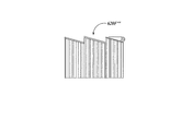
本発明の別の態様によれば、様々の具体的な実施態様においては、光学経路アレイ要素は、互いに平行な光ファイバから成る光ファイバの束、平らな物体光入力面を形成する複数の互いに平行な光ファイバの入力末端、および参照面を備える。 According to another aspect of the present invention, in various specific embodiments, the optical path array element is a bundle of optical fibers comprised of optical fibers parallel to each other, a plurality of each other forming a flat object light input surface. A parallel optical fiber input end and a reference surface are provided.
本発明のさらに別の態様によれば、互いに平行な光ファイバは円筒形である。一部の実施態様においては、互いに平行な光ファイバの直径は最小3μm、最大80μmである。なお、光ファイバを円筒形にするとは、必ずしも完全な円筒形にする場合のみならず、凡そ円筒形であればよい。
ただし、これは一例に過ぎず、限定的なものではない。精度の低い様々な別の実施態様においては、これよりも長い直径(最大200μm以上)であってもよい。
According to yet another aspect of the invention, the optical fibers parallel to each other are cylindrical. In some embodiments, the optical fibers parallel to each other have a minimum diameter of 3 μm and a maximum of 80 μm. Note that the optical fiber is not limited to a perfect cylindrical shape, but may be a substantially cylindrical shape.
However, this is only an example and is not limiting. In various other embodiments with low accuracy, longer diameters (up to 200 μm or more) may be used.
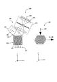
本発明の別の態様によれば、様々の具体的な実施態様においては、光学経路アレイ要素は、共面アキシコンレンズの2次元アレイを備え、この共面アキシコンレンズの2次元アレイは、ターゲット部材からの入力物体光が複数のアキシコンレンズに入力され、複数の各アキシコンレンズの少なくとも円錐状表面で屈折して、角度フィルタ部で受光される出力物体光を提供するように配置されている。 According to another aspect of the invention, in various specific embodiments, the optical path array element comprises a two-dimensional array of coplanar axicon lenses, the two-dimensional array of coplanar axicon lenses comprising: The input object light from the target member is input to the plurality of axicon lenses, and is refracted at least at the conical surface of each of the plurality of axicon lenses so as to provide output object light received by the angle filter unit. ing.
本発明のさらに別の態様によれば、各アキシコンレンズの円錐状表面は、突き出た表面またはへこんだ表面のいずれかである。一部の実施態様においては、各アキシコンレンズの中心軸から端部または半径方向の限界までの平均半径方向寸法の2倍は最小3μm、最大150μmである。 According to yet another aspect of the invention, the conical surface of each axicon lens is either a protruding surface or a recessed surface. In some embodiments, twice the average radial dimension from the central axis of each axicon lens to the edge or radial limit is a minimum of 3 μm and a maximum of 150 μm.
本発明のさらに別の態様によれば、様々の具体的な実施態様においては、各アキシコンレンズの円錐状表面はターゲット部材の方を向いており、角度フィルタ部の方向選択特性により、共面アキシコンレンズの面に対してほぼ垂直な方向に沿って屈折する出力物体光の方向選択された光線だけを伝送することができる。 According to yet another aspect of the present invention, in various specific embodiments, the conical surface of each axicon lens faces the target member and is coplanar due to the direction selection characteristics of the angle filter portion. Only direction-selected rays of the output object light that refract along a direction substantially perpendicular to the axicon lens plane can be transmitted.
本発明の別の態様によれば、様々な典型的な実施態様においては、本発明による光学経路アレイ要素の各光学経路要素は、屈折アキシコン型レンズ、平面で囲まれた錐体型の屈折性レンズ、プリズム断面を有する比較的細長いリッジ型要素、屈折アキシコン型レンズとほぼ同様に光線を偏向させる回折光学素子、平面で囲まれた錐体型の屈折性レンズとほぼ同様に光線を偏向させる回折光学素子、またはプリズム断面を有する比較的細長いリッジ型要素とほぼ同様に光線を偏向させる回折光学素子のいずれかを備える。
このような共面レンズの2次元アレイは、ターゲット部材からの入力物体光が複数のレンズに入力され、レンズにより効果的に偏向されて、各フィルタ部により受光される出力物体光を提供するように配置される。
According to another aspect of the invention, in various exemplary embodiments, each optical path element of the optical path array element according to the invention comprises a refractive axicon-type lens, a cone-shaped refractive lens surrounded by a plane. Diffractive optical element that deflects light rays almost like a refractive axicon type lens, diffractive optical element that deflects light rays almost like a cone-shaped refractive lens surrounded by a plane Or a diffractive optical element that deflects light in substantially the same manner as a relatively elongated ridge-shaped element having a prism cross-section.
In such a two-dimensional array of coplanar lenses, input object light from the target member is input to a plurality of lenses, and is effectively deflected by the lenses to provide output object light received by each filter unit. Placed in.
本発明の別の態様によれば、各光学経路要素は、プリズム断面を有する比較的細長いリッジ型要素を備え、ターゲット部材は、ターゲット部材のそれぞれの領域を一意に特定するのに使用可能なそれぞれの固有なパターンを複数備える。 In accordance with another aspect of the present invention, each optical path element comprises a relatively elongated ridge-shaped element having a prism cross-section, and the target member can each be used to uniquely identify a respective region of the target member. A plurality of unique patterns are provided.
以下、本発明の実施の形態を図示するとともに図中の各要素に付した符号を参照して説明する。
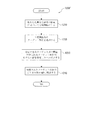
図1は、本発明による光学経路アレイ要素(OPA要素)として使用可能な光ファイバ束に含まれるそれぞれ別の場所に位置決めされた単一の光ファイバ121’および121’’の働きを示す光ファイバ光学経路アレイ(OPA)構成100の等角図である。
DESCRIPTION OF EMBODIMENTS Hereinafter, embodiments of the present invention will be illustrated and described with reference to reference numerals attached to respective elements in the drawings.
FIG. 1 illustrates the operation of a single
以下にさらに詳細に述べるように、本発明による位置センサの様々の具体的な実施態様においては、角度フィルタリング配置により、位置センサのOPA要素として使用される光ファイバ束のそれぞれの光ファイバから特定のそれぞれの実施可能な方向に沿って出力される光だけが位置センサの光学検出器に到達するようになる。
このため、以下の説明において参照する実施可能な極角αは、図2を参照して以下に詳細に述べるように、本発明による様々の具体的な実施態様における特定の位置センサの特定の配置により規定される。
したがって、わかりやすいように、図1では、点115および/または光ファイバ121’および121’’の入力末端を、規定された実施可能な角度αに適合する「選択された」位置に示している。
As will be described in more detail below, in various specific embodiments of the position sensor according to the present invention, the angular filtering arrangement allows the specific optical fiber of each of the optical fiber bundles used as the OPA element of the position sensor to be identified. Only light output along each possible direction will reach the optical detector of the position sensor.
Thus, the feasible polar angle α referred to in the following description is a specific arrangement of specific position sensors in various specific embodiments according to the present invention, as will be described in detail below with reference to FIG. It is prescribed by.
Thus, for the sake of clarity, in FIG. 1, the
ただし、一般的な場合に、点115と光ファイバ121’および121’’の入力末端により、実施可能な極角αが規定されると理解すべきではない。
むしろ、一般的な場合に、規定された実施可能な極角αに適合しないように位置決めされた点と光ファイバの入力末端の組み合わせは実施不可である。
すなわち、α以外の入射角に対応する光学経路は、本発明による様々の具体的な実施態様における実施可能な極角αを規定する角度フィルタリング配置により遮断される。
However, in the general case, it should not be understood that the feasible polar angle α is defined by the
Rather, in the general case, a combination of a point positioned so as not to conform to the defined feasible polar angle α and the input end of the optical fiber is not feasible.
That is, optical paths corresponding to incident angles other than α are blocked by an angular filtering arrangement that defines a feasible polar angle α in various specific embodiments according to the present invention.
図1は、光ファイバ121’からのそれぞれの実施可能な方向/光学経路126と、光ファイバ121’’からのそれぞれの実施可能な方向/光学経路126’を示している。図1に示した典型的な光ファイバOPA構成100においては、実施可能な方向/光学経路126および126’の、実施可能な方向は互いに平行である。光ファイバ121’および121’’はそれぞれ、対応する軸101および101’を有しており、これらの軸も互いに平行である。したがって、実施可能な方向/光学経路126および126’はそれぞれ、軸101および101’を中心として縦方向に同じ角度(図示していない)を成している。さらに、実施可能な方向/光学経路126および126’はそれぞれ、軸101および101’に対して同じ実施可能な極角αを成している。
FIG. 1 illustrates each possible direction /
図1に示したように、2本の光ファイバ121’および121’’は、点115に対してそれぞれ実施可能な位置に位置決めされた光ファイバである。すなわち、光ファイバ121’および121’’の軸101および101’はそれぞれ、光ファイバ121’および121’’それぞれが、それぞれの軸に対して実施可能な極角αをなして点115から光を受光することができるように位置決めされる。具体的には、光ファイバ121’は軸101に沿った方向にあり、図1におけるその下端(入力末端または前端)において、点115からの光線の細いビーム103を受光する。言い換えれば、光ファイバ121’の前端は、点115からの光がファイバ軸101に対して実施可能な極角αを成して前端に入るという条件を満たす位置にある。以下にさらに詳細に述べるように、光線103からの光は、光ファイバ121’の上端または後端から抜けて光円錐125を形成する。
As shown in FIG. 1, the two
光ファイバ121’は内部反射により光を入力末端面から他方の末端に伝えるため、光線のビーム103の公称角度αが保たれる。すなわち、ファイバ121’の末端が、末端での屈折を無視できるほどその軸101に対して名目上垂直であると仮定すれば、実施可能な極角αを成してファイバ121’に入る光は、実施可能な公称円錐角αを有する光円錐125の周囲に分布するファイバの他方の末端から抜ける。さらに、光ファイバ121’が点115から受光する光は角度βを成し、光ファイバ121’の出力において、光円錐125は、軸101に対して半径方向に沿った平面において同じ角度βを名目上成している。
Since the
前述のように、実施可能な方向/光軸126とほぼ平行に出力される光円錐125の光は、本発明による位置センサの角度フィルタリング配置を通過し、位置センサの光学検出器に到達する。本発明による様々の具体的な実施態様においては、光学検出器は2次元アレイ検出器であり、実施可能な方向/光軸126とほぼ平行に出力される光円錐125の光は、光学検出器のそれぞれのピクセルまたは小さいピクセル群に当たって、光学検出器上に画像の一部分を形成する。
As mentioned above, the light in the
光ファイバ121’’の働きは、光ファイバ121’と同様である。具体的には、光ファイバ121’’は軸101’に沿った方向にあり、光ファイバ121’’の前端は、点115からの光がファイバ軸101’に対して実施可能な極角αを成して入力末端に入るという条件を満たす位置にある。点115からの光線の細いビーム104が光ファイバ121’’を通り、その後端から抜けて、実施可能な公称円錐角αを有する光円錐125’を形成する。このため、実施可能な方向/光軸126’とほぼ平行に出力される光円錐125’の光は、本発明による位置センサの角度フィルタリング配置を通過し、光学検出器に到達する。前述のように、様々の具体的な実施態様においては、光学検出器は2次元アレイ検出器であり、光軸126’とほぼ平行に出力される光は、光学検出器のそれぞれのピクセルまたは小さいピクセル群に当たって、光学検出器上に画面の別の一部分を形成する。
The function of the
したがって、本発明による様々の具体的な実施態様においては、同じ点115が光学検出器上の複数の位置に結像される。例えば、図1に示した光ファイバOPA構成100の実施態様では、同じ点115が、2つの個別の光学経路126および126’に沿って伝送される光を受光する位置検出器上の2つの位置に結像される。後述のように、光学経路126および126’相互の空間的関係を、光学検出器に到達する前に様々な光学素子により変更してもよい。
Thus, in various specific embodiments according to the present invention, the
図1に示したように、光ファイバの入力末端は、光ファイバ軸101および101’と平行である円錐軸141、点115に位置決めされた頂点、および実施可能な極角αに等しい円錐角とを有する仮想円錐142の表面上に位置する。仮想面145と一般的な寸法ZおよびRも図1に示している。仮想面145は点115に接しており、円錐軸141に対して垂直である。寸法Zは、仮想面145に対して垂直な方向に沿った光ファイバ入力末端と仮想面145との距離であり、距離Rは、点115から、光ファイバ軸が仮想面145と交差する点までの半径である。
As shown in FIG. 1, the input end of the optical fiber has a
この具体的な実施態様においては、光ファイバの入力末端が仮想円錐142上に位置決めされていない場合、点115は、前述のようには光学検出器上に結像されない。逆に言えば、この具体的な実施態様においては、円錐軸141と平行な軸と、円錐142上に位置決めされた入力末端とを有する任意の光ファイバが、前述のように光学検出器上に点115の画像を生成するように調整可能に位置決めされる。さらに、この具体的な実施態様のこの条件を満たすには、寸法Z(またはZ’など)が増えた場合、実施可能な極角αに応じて円錐142上に光ファイバ入力末端が実施自在に位置決めされるように、対応する寸法R(またはR’など)も増えなければならない。
In this specific embodiment, if the input end of the optical fiber is not positioned on the
光ファイバ121’および121’’は、それぞれ平行な軸を有する光ファイバセットと、ファイバ軸に対してほぼ垂直である平面を形成する入力末端とを備える高密度実装の光ファイバ束に含まれる、本発明による様々の具体的な実施態様における光ファイバを代表するものである。このような場合、点115に対して、ZおよびRは、実施可能な光ファイバ入力末端それぞれについて同じであり、実施可能な入力ファイバ末端は図1に示した円143などの円上に位置する。
The
例えば、Z=Z1である場合、実施可能な光ファイバ入力末端は、半径R1=Z1/tanαの円を形成する一連の入力末端となる。様々の具体的な実施態様においては、半径R1の円に対応する画像が、本発明による位置センサ配置の光学検出器上に形成される。点115と、ファイバ121’および121’’を含むファイバ束との距離間隔がZ=Z2に増えた場合、実施可能な光ファイバ入力末端は、異なる光ファイバセットの新しい一連の入力末端となり、半径R2=Z2/tanαのより大きい円を形成する。したがって、様々の具体的な実施態様においては、半径R2のより大きい円に対応するより大きい画像が、本発明による位置センサ配置の光学検出器上に形成される。
For example, if Z = Z 1 , the possible fiber optic input ends are a series of input ends forming a circle of radius R 1 = Z 1 / tan α. In various specific embodiments, an image corresponding to a circle of radius R 1 is formed on the optical detector of the position sensor arrangement according to the invention. If the distance between the
このため、より一般的には、本発明による様々な位置センサ配置においては、位置センサ配置の光学検出器上に結像されるターゲット点により、ターゲット点と位置センサ配置のファイバ束の入力末端との距離間隔に応じて大きさが変化する対応するターゲット形状の画像が生成される。位置センサ配置のファイバ束が、図1に示した座標系140により定義されるX軸またはY軸に沿って点115に対して移動しなければ、実施可能な入力末端の円の公称中心は変化しない。したがって、このような場合に位置センサ配置の光学検出器上に結像される点の対応する画像特徴の公称中心位置は、Z値の変化に伴うターゲット形状の画像の大きさの変化に関係なく、位置検出器上で変化しない。
Thus, more generally, in the various position sensor arrangements according to the invention, the target point imaged on the optical detector of the position sensor arrangement causes the target point and the input end of the fiber bundle of the position sensor arrangement to An image of a corresponding target shape whose size changes according to the distance interval is generated. If the fiber bundle of the position sensor arrangement does not move relative to the
しかし、位置センサ配置のファイバ束が、X軸またはY軸に沿って点115に対して移動する場合、実施可能な入力末端の円の公称中心が変化し、それに応じて画像形状の公称中心も光学検出器上で変化する。したがって、前述のように、本発明による位置センサ配置では、様々の具体的な実施態様において少なくとも1つのターゲット点を結像させることができ、単一の点と位置センサアレイとの間の3次元相対位置、および/またはこの3次元相対位置の任意の成分を確定するのに使用可能な画像を光学検出器上に提供することができる。
However, if the fiber bundle of the position sensor arrangement moves relative to the
図2は、本発明による位置センサ配置200の第1の一般的な実施態様の詳細な部分図である。図2に示したように、位置センサ配置200には、ターゲット点215および216を含むターゲット部材210、物体光入力面222と物体光出力面223を備えるOPA要素220(図2に示した光ファイバ束を含む)、角度フィルタ部250の具体的な実施態様、および検出器アレイ230が含まれる。
FIG. 2 is a detailed partial view of a first general embodiment of a
具体的な角度フィルタ部250には、焦点距離fのレンズ256、アパーチャ255、および焦点距離fのレンズ257が含まれる。OPA要素220は、それぞれ前述の光ファイバ121’または121’’と働きが似ている光ファイバ群から形成される光ファイバ束として提供してもよい。図2に示した実施態様においては、光ファイバ束は、それぞれ平行な軸を有する光ファイバセットと、ファイバ軸に対してほぼ垂直である平面を形成する入力末端および出力末端とを備える高密度実装のファイバ束である。ここで、OPA要素220の物体光出力面223であるファイバ軸の底面(出力末端)がOPA要素220の参照面224となる。
The specific
様々の具体的な実施態様においては、ターゲット部材210は、明るい背景上に複数の暗いスポットを含むか生成する。別の実施態様においては、ターゲット部材210は、暗い背景上に複数の明るいスポットを含めるかまたは生成する。いずれの場合でも、スポットの働きは前述の点115と似ている。図2に示したターゲット点215は、このようなスポットを表している。
In various specific embodiments, the
図2に示したように、ターゲット点215からの光線を、光ファイバ入力末端の実施可能なリングまたは円が受光する。ここで、リングの大きさ2aは、ファイバ束とターゲット点215との距離によって決まる。一般に、OPA要素220を形成するファイバ束のすべての光ファイバが、ターゲット部材210の表面上の一連の点からの光を受光する。しかし、前述のように、また以下にさらに詳細に述べるように、図2に示した具体的な実施態様においては、ファイバの表面法線から角度αを成して角度フィルタ部250の光軸258と平行に、OPA要素220を形成するファイバ束から抜ける光線だけを検出器アレイ230が受光するように、角度フィルタ部250が配置される。このため、このような実施可能な光線だけを図2で強調しているのである。
As shown in FIG. 2, a light beam from the
仮想面245は、前述の仮想面145と同様に定義される。寸法Z215は、光ファイバの軸と平行な方向に沿った、OPA要素220を形成するファイバ束とターゲット点215との距離間隔を表す。Z>0である場合、大きさが2aである光ファイバの実施可能な円により、検出器アレイ230上に楕円形の画像が生成される。この画像が検出器アレイ上で楕円形になるのは、実施可能な光ファイバの出力末端の実施可能な円が縮められるからである。この縮みが生じる原因は、光軸258と、出力末端の実施可能な円の平面に対して垂直である軸とが角度αを成しているからである。楕円の短径は2bに等しく、図2のページと平行な平面上に位置する。楕円の長径は2aに等しく、図2のページに対して垂直な平面上に位置する。長径と短径は、次のように記述することができる。
The
![]()
![]()
![]()
![]()
したがって、角度αが既知であるため、アレイ検出器230により得られる画像における楕円の長径および/または短径に基づいて高さZを確定することができることは明白である。前述のことから、本発明による様々の具体的な実施態様においては、ターゲット点215などの点形状から生成される画像の大きさと形状は、ターゲット部材210の方向ではなくターゲット点のZ座標によってのみ決まる。
Thus, since the angle α is known, it is clear that the height Z can be determined based on the major axis and / or minor axis of the ellipse in the image obtained by the
前述のように、ターゲット点215が平面245のX軸に沿ってΔX平行移動され、Y軸に沿ってΔY平行移動された場合、楕円の画像中心位置がアレイ検出器230上の対応する方向に沿って平行移動する。特に、図2に示した位置センサ配置200の第1の具体的な実施態様では、X軸に対応する画像平行移動は、縮みが原因でΔXcosαと等しくなり、Y軸に対応する画像平行移動はΔYとなる。したがって、これらの方法により、本発明による位置センサ配置では、ターゲット点215と位置センサ配置との間の平行移動の3自由度(ここでは、一般に、X、Y、Zとする)に沿った位置を測定することができる。
As described above, when the
さらに、本発明による様々の具体的な実施態様においては、ファイバ軸に対して垂直な方向に沿ったOPA要素220を形成する光ファイバの寸法が、図2に図式的に示した寸法を超え、角度フィルタ部250と検出器アレイ230の寸法も同様に、光軸258に対して垂直な方向に沿って長くなる。したがって、このような実施態様では、ターゲット部材210上の別のターゲット点との間隔が既知である複数のターゲット点を同時に結像させることができる。図2に示したターゲット点215とターゲット点216は、このような点を表している。
Further, in various specific embodiments according to the present invention, the dimensions of the optical fiber forming the
ターゲット215と同様に、ターゲット点216は平面245と似た平面245’を規定し、寸法Z216に対応するZ軸位置を持つ。ターゲット点216のX位置、Y位置、およびZ位置も前述のように確定することができる。したがって、2つの確定されたターゲット点215および216と、ターゲット部材210上におけるこれらの点間の既知の間隔に基づいて、ターゲット点215および216を結ぶ線に沿ったターゲット部材210の角度方向も、周知の方法により2つの平面で確定することができる。このため、本発明によるポジション検出配置では、少なくとも2つのターゲット点を含むターゲット部材について、X、Y、Zなど平行移動の3自由度と少なくとも1つの回転自由度(または角度自由度)に沿ってターゲット部材に対する相対位置を測定することができる。
Similar to target 215,
前述のことから類推すれば、ターゲット部材210上の間隔が既知である1つ以上の追加ターゲット点のX位置、Y位置、およびZ位置も前述のように確定することができる。したがって、間隔が既知であり、ターゲット部材210などのターゲット部材上の平面を定義する少なくとも3つのターゲット点があれば、本発明によるポジション検出配置では、ターゲット部材に対する位置と方向を、X、Y、Zなど平行移動の3自由度と3つの回転自由度(または角度自由度)を含めて測定することができる。
By analogy with the foregoing, the X position, Y position, and Z position of one or more additional target points whose spacing on the
ターゲット部材210はどのような所望の大きさでもよく、ターゲット点215および216など複数のターゲット点を含む様々な種類のパターンを含むことができる。具体的な一実施態様においては、ターゲット部材210には、2本の直交軸に沿って規則正しいピッチで配置された点形状のアレイが含まれる。このようなターゲット部材から生成される画像については、図3を参照して後述する。
The
様々の具体典型的な実施態様においては、ターゲット部材210は、検出器アレイ230の視野よりも大きい。検出器アレイは、適合性のある信号処理ユニットに実施自在に接続される。前述のように、また以下にさらに詳細に述べるように、この信号処理ユニットは、検出器アレイのピクセルデータを受け取り、ターゲット部材上の様々なパターン要素から生成される画像形状を解析することができる。
In various specific exemplary embodiments, the
様々の具体的な実施態様においては、ターゲット部材210の累積される動きを追跡するために、信号処理ユニットが、所望の繰返し率またはフレーム率でターゲット部材210から生成される連続した画像を入力し解析する。この動きには、ターゲット部材210上に配置された形状の2次元アレイの一方の方向または両方の方向に沿って、1つのピッチ増加量および/または1つの「視野」増加量を超えるターゲット部材210の動きが含まれる。このような場合、ターゲット部材210上のターゲット要素の既知のピッチまたは間隔が、本発明による位置検出配置とターゲット部材との間の全相対移動量を精密に確定するのに使用可能なスケールとなる。
In various specific embodiments, in order to track the accumulated movement of the
ファイバ軸に対して垂直なX−Y平面上の諸方向に沿った累積される動きを追跡する方法の1つが、画像相関法である。応用可能な様々な相関方法が、米国特許第6,642,506号と、米国特許出願09/9876,162、09/987,986、09/860,636、09/921,889、09/731,671、09/921,711においてて開示されているが、これらをここに参照としてすべて組み込む。 One method for tracking accumulated motion along directions on the XY plane perpendicular to the fiber axis is the image correlation method. Various correlation methods that can be applied are described in US Pat. No. 6,642,506 and US patent applications 09 / 9876,162, 09 / 987,986, 09 / 860,636, 09 / 921,889, 09/731. , 671, 09 / 921,711, all of which are incorporated herein by reference.
Z軸方向(すなわちファイバ軸と平行な方向)に沿った所望範囲の位置を確定できるように、本発明による位置検出配置を設計または最適化してもよい。当然ながら、このZ範囲が存在するのは、位置検出アレイがターゲット部材と接触する位置までである。これにより、様々な典型的な実施態様におけるZ範囲のZminimum(Zの最小値)が定義される。様々な典型的な実施態様においては、様々なターゲット要素の画像が検出器アレイ230上で重なり合わない場合、ターゲット要素画像のそれぞれのZ座標を確定するためのターゲット要素画像解析に関するシグナル処理は簡素化される。したがって、このような実施態様では、ターゲット部材210上のターゲット要素の最小間隔またはピッチは、Z範囲の所望のZmaximumと実施可能な極角αを考慮した次の関係に従って選択される。
The position detection arrangement according to the present invention may be designed or optimized so that a desired range of positions along the Z-axis direction (ie, parallel to the fiber axis) can be determined. Of course, this Z range exists up to the position where the position detection array contacts the target member. This defines the Z minimum (Z minimum) of the Z range in various exemplary embodiments. In various exemplary embodiments, if the images of the various target elements do not overlap on the
![]()
![]()
様々な別の具体的な実施態様においては、最小間隔は上記の関係を満たす値を下回る。また、それぞれのターゲット要素画像が検出器アレイ230により検出される画像内で重なり合う場合でも、複雑な画像処理を用いて様々なターゲット要素のZ座標が確定される。
様々な典型的な実施態様においては、OPA要素220を形成するファイバ束には、高密度実装または最密構造配置で配置されたファイバが含まれる。様々の具体的な実施態様においては、ファイバ軸は、互いに少なくともほぼ平行である。様々の具体的な実施態様においては、個々のファイバが少なくともほぼ円筒形である場合に、画像解析結果の精度および/または繰返し精度が最も高くなる。
In various other specific embodiments, the minimum spacing is below a value that satisfies the above relationship. Also, even if the respective target element images overlap in the image detected by the
In various exemplary embodiments, the fiber bundle forming the
様々なファイバの最密構造の製作方法および/またはファイバ線引き加工などにより、ファイバ断面の歪み(すなわち、非円筒形のファイバ)が生じることがある。例えば楕円や六角形断面などにファイバが歪んでいる場合、ファイバにより出力される実施可能な光円錐が様々な歪みおよび/または不均等な強度分布を示し、その結果、ターゲット部材のZ座標の確定に用いられる様々な画像処理方法に誤りが生じたり、および/または、複雑な信号処理が必要になる可能性がある。それにもかかわらず、より経済的な部品を使用するために精度をある程度犠牲にする様々な別の具体的な実施態様においては、このようなファイバを用いてもよい。 Fiber cross-section distortion (ie, non-cylindrical fibers) may occur due to various fiber close-packed fabrication methods and / or fiber drawing processes and the like. For example, if the fiber is distorted in an elliptical or hexagonal cross section, the feasible light cone output by the fiber exhibits various strains and / or uneven intensity distribution, resulting in the determination of the Z coordinate of the target member. May cause errors in various image processing methods used and / or require complex signal processing. Nevertheless, such fibers may be used in various other specific embodiments that sacrifice some accuracy to use more economical components.
様々の具体的な実施態様においては、個々のファイバ直径は、アレイ検出器230上のピクセルよりも小さい寸法でファイバ直径が結像するように選択される。非常に精密な測定を実現する具体的な一実施態様においては、ファイバ直径は約6μmである。様々な別の具体的な実施態様においては、3μm〜80μm(またはそれ以上)の範囲のファイバ直径が選択される。ただし、これは一例に過ぎず、限定的なものではない。より経済的な部品を使用するために精度および/または分解能をある程度犠牲にする様々な別の具体的な実施態様においては、直径がより長いファイバが用いられる。このような精度の低い実施態様においては、最大200μm以上の、太い直径を用いてもよい。
In various specific embodiments, the individual fiber diameters are selected so that the fiber diameters are imaged with dimensions smaller than the pixels on the
角度フィルタ部250に関しては、図2に示した具体的な実施態様においては、角度フィルタ部250には、OPA要素220を形成するファイバ束の出力末端において提供される画像を拡大も縮小もしない両側テレセントリック配置で配置された、2つのレンズと1つのアパーチャが含まれる。図2の実施態様では、レンズ256および257を片面凸レンズとして示しているが、本発明により実施可能な両面凸レンズなど、その他のレンズ構成を用いてもよい。
With respect to the
当業者にとって周知のように、テレセントリック配置では一般に、テレセントリック配置の光軸258とほぼ平行である光線だけが伝送される。このため、OPA要素220を形成するファイバ束に対する角度フィルタ部250の配置および/または方向角により、調整可能な角度αが規定される。また、周知のように、テレセントリック配置では、オブジェクト面(1つまたは複数)からテレセントリック配置までの距離に少なくともほとんど依存しない倍率(図2に示した実施態様においては1:1の倍率)が実現される。図2に示した両側テレセントリック配置でも同様に、テレセントリック配置から画像面(すなわち、アレイ検出器230の平面)までの距離に依存しない画像倍率(図2に示した実施態様においては1:1の倍率)が実現される。
As is well known to those skilled in the art, a telecentric arrangement generally transmits only light rays that are substantially parallel to the
ただし、様々な別の具体的な実施態様においては、レンズ257が角度フィルタ部250から取り除かれ、アパーチャ255から距離fを隔てて、レンズ257の代わりにアレイ検出器230がアパーチャ255とレンズ256に対して固定して取り付けられる。この構成においても、画像倍率1:1が実現される。様々な別の具体的な実施態様においては、1:1以外の所望の拡大または縮小を実現するために、カメラがアパーチャ255から別の距離を隔てて取り付けられる。
However, in various other specific embodiments, the
前述の実施態様においては、テレセントリック配置での役割に加え、レンズ256の焦点特性により、アパーチャ255を通過する光を集中させて、検出器アレイ230における画像強度が高められるという利点がもたらされる。レンズ256がなければ、角度フィルタ部250がテレセントリックではなくなり、OPA要素220から得られる光全体よりも多くの光がアパーチャ255により除外されるという欠点が生じる。それにもかかわらず、アパーチャ255だけを含む角度フィルタ部250は、より経済的な部品を使用するために精度および/または画像処理の簡易性をある程度犠牲にする、本発明による様々の具体的な実施態様において使用可能である。ただし、このような実施態様では、アレイ検出器230において画像強度とS/N比が低下する。さらに、このような実施態様では、ターゲット部材210上の様々なターゲット要素のZ座標を確定するために、より複雑な画像処理が必要になる。その理由は、角度フィルタ部250にテレセントリック配置がないため、アレイ検出器230上の画像の各部分の有効倍率が異なってくるからである。
In the embodiment described above, in addition to its role in the telecentric arrangement, the focus characteristic of the
図2では、寸法Wも示している。この寸法は、ターゲット部材210上のターゲット点によりアレイ検出器上に生成される前述の楕円などを形成する「画像線」の公称幅である。本発明による様々の具体的な実施態様においては、幅Wは、有効な個別のファイバアパーチャおよび/またはアパーチャ255の大きさおよび/またはレンズ256の焦点効果および/またはレンズ257によって決まる。本発明による位置センサ配置の全体的な精度は、前述の楕円などを形成する「画像線」の各部分の位置を確定する際の分解能に少なくともある程度依存する。
In FIG. 2, the dimension W is also shown. This dimension is the nominal width of the “image line” that forms the aforementioned ellipse or the like generated on the array detector by the target points on the
このため、本発明による様々の具体的な実施態様においては、後述のように、「画像線」の各部分の公称位置の確定、適合、または推定はサブピクセル分解能で行なわれる。したがって、様々の具体的な実施態様においては、様々な画像形状の位置決めのためのサブピクセル補間処理を容易にするために、本発明による位置センサ配置は、公称幅Wが画像検出器230上で少なくとも3ピクセルとなるように設計される。より高い精度を実現する様々な別の具体的な実施態様においては、公称幅Wはアレイ検出器230上で最小3ピクセル、最大6ピクセルである。より経済的な部品を使用するために精度および/または画像処理の簡易性をある程度犠牲にする別の具体的な実施態様においては、幅Wは3ピクセル未満であるか6ピクセルを超える。
Thus, in various specific embodiments according to the present invention, as described below, the determination, adaptation, or estimation of the nominal position of each portion of an “image line” is performed with sub-pixel resolution. Thus, in various specific embodiments, the position sensor arrangement according to the present invention has a nominal width W on the
ターゲット部材210に関しては、様々の具体的な実施態様においては、ターゲット点215などは、ターゲット部材210のレイヤにおけるピンホール形状により提供される。このレイヤは、ターゲット部材210上の同様のピンホールまたはその他の所望のパターン要素を除いて不透明である。このような実施態様においては、ターゲット部材210には、様々なピンホール形状を通して光を伝送させるように配置された光源が含まれる。様々な別の具体的な実施態様においては、類似の画像効果は、ターゲット部材210のレイヤにおける「反射ピンホール」であるターゲット点215により達成される。このレイヤは、ターゲット部材210上の同様の反射ピンホールまたはその他の所望のパターン要素を除いて非反射である。
With respect to the
このような一実施態様においては、ターゲット部材210は、位置センサ配置に面するターゲット部材210の上側から拡散照明され、反射ピンホール形状は、ターゲット部材210に塗付されたまたははめ込まれたまたは形成された小型コーナーキューブを備える。様々の具体的な実施態様においては、このようなコーナーキューブの寸法は10ミクロン未満であってもよく、様々な周知のエンボス加工および/または蒸着法により形成してもよい。
In one such embodiment, the
コーナーキューブから成るターゲットは、検出に適した角度で効率的に光をリードヘッドに戻すのに非常に有効である。ただし、これらのターゲット形状は、ターゲット形状に当たる光が全方向に送られるように拡散体であってもよい。一実施態様においては、これらの形状の間に存在するターゲットの部分は、レジストや黒色クロムなど光吸収物質である。コーナーキューブのアレイである3Mダイヤモンドグレード(3M Diamond Grade Reflective)シート(米国ミネソタ州セントポール、3M Centerの3M Corporate Headquartersで入手可能)のような物質は、反射しないレジストを部分的に塗付して、このようなターゲットの物質として最初に使用できる。一実施態様においては、このターゲットのコーナーキューブ寸法は約数ミクロンである。 A target consisting of a corner cube is very effective in efficiently returning light to the readhead at an angle suitable for detection. However, these target shapes may be diffusers so that light hitting the target shape is sent in all directions. In one embodiment, the portion of the target that exists between these shapes is a light absorbing material such as resist or black chrome. Materials such as the 3M Diamond Grade Reflective sheet, which is an array of corner cubes (available at 3M Corporate Headquarters, 3M Center, St. Paul, Minnesota, USA) can be partially coated with a non-reflective resist. Can be used first as such target material. In one embodiment, the corner cube dimension of the target is about a few microns.
様々な別の具体的な実施態様においては、ターゲット点215は、ターゲット部材210のレイヤにおける「反転ピンホール」形状により提供することができる。このレイヤは、ターゲット部材210上の同様の反転ピンホールまたはその他の所望のパターン要素を除いて乱反射率が高い。この場合にも、3Mダイヤモンドグレード反射(3M Diamond Grade Reflective)シートのような物質は、このようなターゲットの物質として最初に使用できる。このような実施態様においては、ターゲット部材210は、位置センサ配置に面するターゲット部材210の上側から照明され、光を反射しない様々な反転ピンホールを除くあらゆる箇所で光を乱反射する。
In various other specific implementations, the
本発明によるターゲット点から生成される光の働きは、様々の具体的な実施態様において前述したように、または以下にさらに詳細に述べるように、前述のものに比べ「ネガ画像」により提供される。すなわち、前述の明るい経路と明るい円錐は、この場合「暗い経路」と「暗い円錐」であり、ターゲット点の画像は、この場合、明るい背景に囲まれた画像の「暗い部分」である。このような「反転画像」処理により、位置センサ配置200の他の実施態様と、本発明による様々な別の位置検出配置がもたらされることは明白である。
The action of light generated from target points according to the present invention is provided by a “negative image” compared to the foregoing, as described above in various specific embodiments, or as described in more detail below. . That is, the above-mentioned bright path and bright cone are “dark path” and “dark cone” in this case, and the image of the target point is in this case “dark part” of the image surrounded by a bright background. Obviously, such "inverted image" processing results in other embodiments of the
ここではターゲット部材210を一般に、個別の要素として示しているが、様々の具体的な実施態様においては、ターゲット部材210は、本発明により使用可能なターゲット形状を含む、機械部分または可動ステージの表面を備えてもよい。さらに、ここではターゲット形状を一般に、点として示しているが(このような点が、ターゲット形状に対応する画像形状の大きさと位置を確定する最も簡単な画像処理手順のいずれかと適合性があるため)、より一般的には、ターゲット形状は、変換や畳み込みなどを含む実用的な画像処理手順により確定できる大きさと位置を有する画像形状を生成する任意の形状であり得る。これらの他のターゲット部材およびその他の様々な他のターゲット部材は、本開示の利益を享受する当業者にとって明白であろう。
Although the
具体的な一実施態様においては、角度フィルタ部250の光学部品は、図2に示した寸法fが約20mm、角度αが約15度、アパーチャ255の直径が約0.5mmとなるように選択され配置される。OPA要素220を形成するファイバ束は、光ファイバ軸と平行である約10mmの寸法Lと、x軸およびy軸に沿った約12mmの寸法を有し、光ファイバ直径dは約6μmである。ターゲット点の寸法は約100μmであり、ターゲット点はターゲット部材210上で2本の直交軸に沿って1.0mmのピッチで互いに隔たっている。
In one specific embodiment, the optical components of the
アレイ検出器230の大きさは約4.7mm×3.5mmであり、直交する行方向および列方向に沿って約7.4μmのピッチで配置された640列×480行のピクセルが含まれる。OPA要素220を形成するファイバ束の底面または参照面からターゲット部材までの公称の動作距離は約1.0mm+/−0.5mmである。後述のように、画像処理が適切であれば、このような構成により、X、Y、Zの平行移動については約1〜2μm、ロール角、ピッチ角、およびヨー角については約0.05度の分解能と精度をそれぞれ実現することができる。様々の具体的な実施態様においては、適切なアレイ検出器とDSPを用いて、最大1000Hz以上のサンプルレートでの6D測定が可能である。
The size of the
前述の具体的な実施態様のパラメータと要素は一例に過ぎず、限定的なものではない。その他にも数多くの実施態様が可能であることは、本開示の利益を享受する当業者にとって明白であろう。
図3A〜図3Fは、本発明によるターゲット部材上に含まれるターゲット点の具体的な一パターンと、検出器アレイ230などの検出器アレイ(カメラとも称する)において形成される、ターゲット点の理想的な輪状画像の様々なパターンを、本発明による様々の具体的な実施態様におけるターゲット部材の様々な方向について示している。図1および図2を参照して説明したように、ターゲット部材上のターゲット点が、カメラにおいて輪状である画像を生成する。
The parameters and elements of the specific embodiments described above are merely examples and are not limiting. It will be apparent to those skilled in the art having the benefit of this disclosure that many other embodiments are possible.
FIGS. 3A-3F illustrate an ideal pattern of target points formed in a specific pattern of target points contained on a target member according to the present invention and a detector array (also referred to as a camera), such as
本発明による様々の具体的な実施態様においては、前述のように、輪状画像は楕円形である。ただし、実施可能な角度αの値が約25度未満である場合、楕円の短径は長径の90%以上であるため、図示するために楕円を円と近似させることができる。一般に、それぞれの輪状画像の寸法(1つまたは複数)は、OPA要素の参照面と、対応するそれぞれのターゲット点との間のZ座標、および実施可能な角度αによって決まる。角度フィルタ部とカメラの配置により1:1の倍率が提供される場合、リングの寸法は式1および式2により得られる。
In various specific embodiments according to the present invention, as described above, the annular image is elliptical. However, when the value of the operable angle α is less than about 25 degrees, since the minor axis of the ellipse is 90% or more of the major axis, the ellipse can be approximated to a circle for illustration. In general, the dimension (s) of each annulus image is determined by the Z coordinate between the reference plane of the OPA element and the corresponding target point, and the feasible angle α. If 1: 1 magnification is provided by the angular filter section and camera placement, the ring dimensions are given by
図3Aは、ターゲット部材上のターゲットパターンとして使用することができるターゲット点アレイ30Aを示している。図3Aに示した実施態様においては、ターゲット点は、ターゲット部材のX軸方向に沿った周期ピッチPxと、ターゲット部材のY軸方向に沿った周期ピッチPyに従って配置される。これは、OPA要素の参照面がターゲット部材とほぼ平行でありターゲット部材と接触している場合のカメラ上の画像でもある。
FIG. 3A shows a
図3Bは、OPA要素の参照面がターゲット部材の平面とほぼ平行であり、Z軸に沿ってある程度離れている場合に、カメラにおいて形成されるリングのアレイ30Bを示している。
図3Cは、ターゲット部材の平面がOPA要素の参照面に対してY軸を中心として回転されている場合に形成されるリングのアレイ30Cを示しており、OPA要素から右端に向かうターゲット点のZ軸距離間隔の方が、左端に向かうターゲット点よりも大きくなっている。
図3Dは、ターゲット部材が図3Cとは反対の方向に傾斜している場合に形成されるリングのアレイ30Dを示している。
FIG. 3B shows an
FIG. 3C shows an
FIG. 3D shows an array of
図3Eは、ターゲット部材の平面がOPA要素の参照面に対してX軸を中心として回転されている場合に形成されるリングのアレイ30Eを示しており、OPA要素から上端に向かうターゲット点のZ軸距離間隔の方が、下端に向かうターゲット点よりも大きくなっている。
図3Fは、ターゲット部材の平面が、OPA要素の参照面に対して、X軸から反時計回りに約45度の角度を成す、X−Y平面と平行である軸を中心として回転されている場合に形成されるリングのアレイ30Fを示している。OPA要素から左上隅に向かうターゲット点の距離間隔の方が、右下隅下に向かうターゲット点よりも大きくなっている。
FIG. 3E shows an
In FIG. 3F, the plane of the target member is rotated about an axis parallel to the XY plane that forms an angle of about 45 degrees counterclockwise from the X axis with respect to the reference plane of the OPA element. An
図2、図3、図4に示したおよび/または暗示した座標系に関して、輪状画像の中心間の間隔は、Y軸を中心とした回転角成分の余弦に応じてX軸に沿って狭くなる。同様に、リングの中心間の間隔は、X軸を中心とした回転角成分の余弦に応じてY軸方向に沿って狭くなる。ただし、特に回転角が小さい場合、リングの中心間の間隔は、相対回転の最良の指標とはならない。むしろ、本発明の特に重要な特長は、それぞれのリングの大きさが、対応するそれぞれのターゲット点のZ座標を高精度に示す指標であるということである。このため、本発明による様々の具体的な実施態様においては、位置センサに対するスケール部材回転の様々な角度成分が、これらの各Z座標と関連のX座標およびY座標を基に高精度で確定される。 With respect to the coordinate system shown and / or implied in FIGS. 2, 3, and 4, the spacing between the centers of the ring-shaped images becomes narrower along the X-axis depending on the cosine of the rotational angle component about the Y-axis. . Similarly, the distance between the centers of the rings becomes narrower along the Y-axis direction according to the cosine of the rotation angle component centered on the X-axis. However, especially when the rotation angle is small, the spacing between the centers of the rings is not the best indicator of relative rotation. Rather, a particularly important feature of the present invention is that the size of each ring is an indicator that indicates the Z coordinate of each corresponding target point with high accuracy. Thus, in various specific embodiments according to the present invention, various angular components of the scale member rotation relative to the position sensor are determined with high accuracy based on each of these Z coordinates and the associated X and Y coordinates. The
ターゲット部材に対する、本発明による位置センサ配置の位置の平行移動成分と回転成分を確定する具体的な方法の1つについて、図5および図6を参照して以下にさらに詳細に述べる。
図4Aおよび図4Bは、一般的な位置センサ配置200と類似または同一の、本発明による位置センサ配置300を、ターゲット点から生成される様々な輪状画像の位置を示す具体的な一連の座標関係とともに示す略図である。図4Aおよび図4Bの様々な寸法間の関係は正確ではなく、図示するために誇張してある。
One specific method for determining the translational and rotational components of the position of the position sensor arrangement according to the present invention relative to the target member will be described in more detail below with reference to FIGS.
4A and 4B show a specific series of coordinate relationships showing the position of various annular images generated from target points in a
位置センサ配置300には、代表的なターゲット点315を含むターゲット部材310とリードヘッド390が含まれる。リードヘッド390は、物体光入力面322と物体光出力面323を有する。位置センサ配置300は、本発明によるOPA要素320、象徴的に表した角度フィルタ部350、およびカメラ330を備える。図4Aおよび図4Bに示した実施態様においては、OPA要素320はファイバ束OPAを備えるが、図4Aおよび図4Bを参照した説明は限定的なものではない。図16〜図20を参照して後述するアキシコン型OPAなど、任意の実施可能なOPAを使用してもよい。3XXという番号が付けられた要素の働きは、図2を参照して前述した2XXという番号が付けられた要素と似ているか同じである。
The
位置確定についての説明の重要な態様がわかりやすくなるように、図4Aでは、角度フィルタ部350の光軸358の方向に沿った寸法を短縮して表している。ここでは、角度フィルタ部350により1:1の倍率が提供されると想定する。さらに、角度フィルタ部350からの出力光線を、対応する入力光線と同じ光軸358の側に図式的に示し、図2のより詳細な実施態様に示した画像反転は無視している。
In FIG. 4A, the dimension along the direction of the
ただし、画像反転を、様々な画像形状のカメラ座標の符号反転で処理してもよいし、別の方法として、位置確定についてのこの簡単な説明に従って確定される様々な位置成分の符号反転で処理してもよい。したがって、図4Aおよび図4Bの目的はこの位置確定方法を概念的および図式的に示すことであり、本発明による様々の具体的な実施態様において角度フィルタ部の働きにより生じる、オブジェクト位置に対する光軸に交差する画像位置の反転は無視される。ただし、この説明に基づいて、本発明による特定の実施態様において必要とされる以下の位置確定方法に対して変更が必要であることは、当業者にとって明白であろう。 However, image inversion may be processed by sign inversion of camera coordinates of various image shapes, or alternatively, processing by sign inversion of various position components determined according to this brief description of position determination. May be. Accordingly, the purpose of FIGS. 4A and 4B is to conceptually and schematically illustrate this position determination method, and in various specific embodiments according to the present invention, the optical axis relative to the object position produced by the action of the angular filter section. The reversal of the image position that intersects is ignored. However, based on this description, it will be apparent to those skilled in the art that changes are required to the following location determination methods required in certain embodiments according to the present invention.
図4Aは、位置センサ配置300をY軸方向に沿って見た図である。図4Bは、位置センサ配置300をX軸方向に沿って見た図である。位置センサ配置300における位置確定手順を概念的に示せば、次のようになる。すなわち、まず様々な画像形状のカメラ座標位置を確定し、次に、様々な座標変換により、対応する光線をカメラからターゲット点315へと逆に辿り、OPA要素320の参照面上の基準点に対するターゲット部材310上のそれぞれのターゲット点315の相対位置を確定する。
FIG. 4A is a view of the
基準点OはOPA要素320の参照面上の点であり、OPA要素320からの物体光の実施可能な出力面と光軸358が交差する点O’に対応する。この具体的な実施態様においては、カメラ330の中心はカメラ座標原点O’’であり、また光軸358と一直線上にある。ターゲット点315など3つの個別ターゲット点の位置がわかれば、ターゲット部材310に対するリードヘッド390の相対位置と方向を計算することができる。
The reference point O is a point on the reference plane of the
ターゲット部材310に対するOPA要素320の相対位置と方向を計算するための第1段階として、OPA要素参照面324(図4Aに示した実施態様においてOPA要素320を形成するファイバ束の底面)上のリングの公称位置と大きさを、その画像の大きさと位置に基づいて確定し、次に、リングを生成するターゲット点(1つまたは複数)315の位置を確定し、次に、これらの位置に対応する、ターゲット部材310またはリードヘッド390の平行移動および回転の相対位置を確定する。
As a first step in calculating the relative position and orientation of the
本発明による様々の具体的な実施態様においては、カメラ座標における輪状画像の大きさと位置を精密に確定するために、画像処理の適応ルーチンがカメラ上の輪状画像に適用される。様々の具体的な実施態様においては、画像処理中に適用される適応ルーチンでは、リングが円であると想定されるため、カメラ上の様々な輪状画像の、フィッティングまたは推定された半径Ric(ここでiは、特定の1つのリングを示す整数である)は、リングの長径と短径を平均した値にほぼ等しい。 In various specific embodiments according to the present invention, an image processing adaptation routine is applied to the annular image on the camera to precisely determine the size and position of the annular image in camera coordinates. In various specific embodiments, the adaptive routine applied during image processing assumes that the ring is a circle, so the fitting or estimated radius R ic ( Here, i is an integer indicating a specific ring) is substantially equal to the average value of the major axis and minor axis of the ring.
![]()
![]()
様々の具体的な実施態様においては、実施可能な角度αは、リングがほぼ円形であるように決められている。このため、様々の具体的な実施態様においては、円フィッティングルーチンよりも楕円フィッティングルーチンを用いた方が高い精度を達成できるにしても、これで十分近似した結果が得られる。OPA要素参照面におけるリングの半径は、次のように推定される。 In various specific embodiments, the operable angle α is determined so that the ring is substantially circular. For this reason, in various specific embodiments, even if higher accuracy can be achieved by using an elliptical fitting routine than by a circular fitting routine, this provides a sufficiently approximate result. The radius of the ring at the OPA element reference plane is estimated as follows.
![]()
![]()
OPA要素参照面におけるリング中心のx−y位置座標は、図4Aおよび図4Bに示した実施態様におけるi番目のターゲット点のx−y座標と同じであり、次のように得られる。 The xy position coordinates of the ring center in the OPA element reference plane are the same as the xy coordinates of the i-th target point in the embodiment shown in FIGS. 4A and 4B, and are obtained as follows.

i番目のターゲット点のz位置座標ziは、次の式から計算される。 The z position coordinate z i of the i th target point is calculated from the following equation.
![]()
![]()
前述のように図4Aおよび図4Bは略図であり、わかりやすいように1つのターゲット点しか示していない。しかし、様々の具体的な実施態様においては、ターゲット点315など少なくとも3つのターゲット点がカメラ330の視野内に常に入る。このため、ターゲット部材310に対して垂直である単位ベクトルを、ターゲット部材310上に位置するこのような3つのターゲット点から導き出すことができる。このような3つのターゲット点の位置により定義される2つのベクトルの外積により、ターゲット表面に対して垂直であるベクトルが生成される。このベクトルを用いて、様々な周知のベクトル代数方法および/または後述の方法により、様々な相対回転成分を確定することができる。
As mentioned above, FIGS. 4A and 4B are schematic and only one target point is shown for clarity. However, in various specific embodiments, at least three target points, such as
図5に示したように、ベクトルriは、OPA要素参照面324’上の座標原点Oとターゲット面上のターゲット点315’〜317’を結ぶ。ベクトルviは、ターゲット部材310’の平面上に存在する。ベクトルr0は、座標原点Oを通る、ターゲット部材310’に対して垂直であるベクトルと定義される。ターゲット部材310’に対して垂直である単位ベクトルntmは、ターゲット部材面上に存在する2つのベクトルviの外積から導き出される。図5に示した例では、ntmは次のように導き出される。
As shown in FIG. 5, the vector r i connects the coordinate origin O on the OPA
![]()
![]()
式8の単位ベクトルntmは、OPA要素の参照面324’に対して垂直であるZ軸に対するターゲット部材310’の傾斜を表す。この単位ベクトルを用いて、2つの直交基準軸を中心としたターゲット部材310’と本発明によるリードヘッドの相対角度方向を、周知のベクトル代数方法により確定することができる。
The unit vector n tm in Equation 8 represents the tilt of the
ターゲット部材310’の局所x基準軸および局所y基準軸のxtm方向およびytm方向は、ターゲット部材310’上の直交軸に沿って周期的に配置されたターゲット点のパターンと同じ平面上にあると定義してもよい。例えば、様々の具体的な実施態様においては、ターゲット点は、xtm方向およびytm方向におけるターゲット点間の距離が、同一の周期ピッチPに等しい(すなわち、Px=Py=P)ような、周期的行および列パターンを成して配置される。
The x tm and y tm directions of the local x reference axis and the local y reference axis of the
様々の具体的な実施態様においては、Z軸を中心とした初期のxtm方向およびytm方向は既知であり、Z軸を中心としたターゲット部材310’の相対的回転は+/−45度以内(または、x軸およびy軸を中心とした傾斜の影響を考慮してこれよりも幾分少なめ)に限定されるか、あるいはZ軸を中心とした正味回転を時間の経過とともに累積するプロセスにより追跡することができる。
In various specific embodiments, the initial x tm and y tm directions about the Z axis are known, and the relative rotation of the
このため、Z軸を中心としたxtm軸およびytm軸のおおよその方向は明確である。したがって、xtm方向またはytm方向に沿ったベクトルを定義するには(ほとんどまたはすべての実用化でそうであるように、x軸およびy軸に対する傾斜が比較的限定されると想定した場合)、最悪でも、選択されたターゲット点(例えば、座標原点Oに最も近いターゲット点)の座標から始めて、この点に最も近く、また互いに最も近い2つのターゲット点を特定するだけで十分である。 Therefore, the approximate direction of the x tm-axis and y tm axis around the Z axis is clear. Therefore, to define a vector along the x tm direction or y tm direction (as do most or all of the practical application, if it is assumed that inclination with respect to the x and y axes are relatively limited) At worst, it is sufficient to start with the coordinates of the selected target point (eg, the target point closest to the coordinate origin O) and identify the two target points closest to this point and closest to each other.
ターゲット部材310’と、リードヘッド390などのリードヘッドとの間で、X−Y平面における相対回転が+/−45度以内に限定されるか、あるいは追跡される場合、最初に選択されたターゲット点とこれら2つのターゲット点とを結ぶそれぞれのベクトルの方向により、xtm方向およびytm方向が明確に特定される。角度の精度を向上させるために、これらの方向に沿ってターゲット点へのベクトルをさらに延長してもよい。
The first selected target if the relative rotation in the XY plane is limited to or tracked within +/− 45 degrees between the
したがって、様々の具体的な実施態様においては、前述のベクトルのいずれかを、次のように、xtm方向およびytm方向に対応する単位ベクトルv(図5のベクトルv1またはv3)として定義することができる。 Thus, in a specific embodiment of various defines any of the aforementioned vectors, as follows, as x tm direction and y tm directions corresponding unit vector v (the vector v1 or v3 in FIG. 5) be able to.
ztm方向に沿った単位ベクトルは、式8で与えられる単位ベクトルntmと同じであるか、あるいは次のように外積から導き出すことができる。 The unit vector along the z tm direction is the same as the unit vector n tm given by Equation 8, or can be derived from the outer product as follows:
![]()
![]()
様々の具体的な実施態様においては、相対方向を確定し、相対位置および方向の6D測定値を完全に定義するために、周知のベクトル代数方法により単位ベクトルから回転マトリクスRが形成される。 In various specific embodiments, a rotation matrix R is formed from unit vectors by well-known vector algebra methods to establish relative directions and to fully define 6D measurements of relative positions and directions.
ここで、単位ベクトルxtm成分の成分xtm,xはそれぞれリードヘッド標系x軸に沿っており、他のベクトル成分についても同様である。回転マトリックスは、周知のベクトル代数方法によれば、リードヘッド座標系においてターゲット部材に適用されるロール回転、ピッチ回転、およびヨー回転を用いて次のように記述することもできる。ここでは、最初にロール(x軸を中心としてθr)、次にピッチ(y軸を中心としてθp)、次にヨー(Z軸を中心としてθy)という順序で回転が適用されると想定する。 Here, the component x tm, x of the unit vector x tm component is along the x axis of the readhead standard system, and the same applies to the other vector components. The rotation matrix can also be described by the known vector algebra method using roll rotation, pitch rotation, and yaw rotation applied to the target member in the readhead coordinate system as follows. Here, when rotation is applied in the order of roll (θ r around the x-axis), then pitch (θ p around the y-axis), and then yaw (θ y around the Z-axis) Suppose.
2つのマトリクスを同等とみなすことで、次のように様々な回転角を導き出すことができる。 By regarding the two matrices as equivalent, various rotation angles can be derived as follows.
![]()
![]()
![]()
![]()
![]()
![]()
別の方法として、ターゲット部材の様々な軸xtm、ytm、およびztmに対するリードヘッドの回転を、類似のベクトル代数方法により、あるいは周知のベクトル代数変換を上記の結果に適用することにより確定してもよい。
様々の具体的な実施態様においては、ターゲット部材に対するリードヘッドの平行移動位置を次のように確定してもよい。まず、図6に示した点Otmを、ターゲット部材の局所軸の現在の原点として定義する。次に、原点Oとターゲット面上の点との間でターゲットの法線ntmまたはztmと平行であるベクトルにより、点Otmを定義する。図6に示したように、これは、ターゲット面のztm軸に沿っており、2つの点(OとOtm)を結ぶベクトルr0である。次に、リードヘッドのZ座標または「ギャップ」をベクトルr0の長さと定義する。ターゲット部材に対するリードヘッドの現在の局所座標xtmおよびytmは、現在のターゲット部材原点Otmを基準とする。
Alternatively, readhead rotation about various axes x tm , y tm , and z tm of the target member can be determined by similar vector algebra methods or by applying well-known vector algebra transformations to the above results. May be.
In various specific embodiments, the translation position of the read head relative to the target member may be determined as follows. First, the point O tm shown in FIG. 6 is defined as the current origin of the local axis of the target member. Next, a point O tm is defined by a vector parallel to the target normal n tm or z tm between the origin O and a point on the target plane. As shown in FIG. 6, this is a vector r 0 that is along the z tm axis of the target surface and connects two points (O and O tm ). Next, the Z coordinate or “gap” of the readhead is defined as the length of the vector r 0 . The current local coordinates x tm and y tm of the read head relative to the target member are relative to the current target member origin O tm .
前述のように、本発明による位置センサ配置を用いて、3つの回転成分とZ座標平行移動成分またはギャップを、任意の単一ターゲット部材画像から確実に確定することができる。ただし、ターゲット部材に対する、xtm方向およびytm方向に沿ったリードヘッドの合計移動量は絶対量でないため、当業者にとって明白な方法またはアルゴリズムを用いて、相対的なxtm平行移動およびytm平行移動の間に、xtm方向およびytm方向に沿ったターゲット点パターンピッチの累積増加量の追跡を含むプロセスにより、この合計移動量を確定する必要がある。さらに、精密測定のためには、1Dおよび2D光学式インクリメンタルエンコーダで使用される周知の方法と似た方法で、ターゲット点パターンの最初のxtm周期およびytm周期内の最初の位置と、ターゲット点パターンの最後のxtm周期およびytm周期内の最後の位置を、xtm累積増分量およびytm累積増分量に追加する必要がある。
ターゲット点パターンの現在のxtm周期およびytm周期内の位置を確定するために、点Otmがベクトルr0により定義される。ベクトルr0は、周知のベクトル代数方法により次のように確定される。
As described above, the position sensor arrangement according to the present invention can be used to reliably determine the three rotation components and the Z coordinate translation component or gap from any single target member image. However, since the total amount of movement of the read head along the x tm and y tm directions relative to the target member is not an absolute amount, the relative x tm translation and y tm can be determined using methods or algorithms that will be apparent to those skilled in the art. during the translation, by a process that includes tracking the cumulative increase of the target point pattern pitch along the x tm direction and y tm direction, it is necessary to confirm this total amount of movement. In addition, for precision measurements, the first position in the first x tm period and y tm period of the target point pattern and the target in a manner similar to that known in the 1D and 2D optical incremental encoders. The last position in the last x tm and y tm periods of the point pattern needs to be added to the x tm cumulative increment and the y tm cumulative increment.
In order to determine the position of the target point pattern within the current x tm period and y tm period, the point O tm is defined by the vector r 0 . The vector r 0 is determined as follows by a well-known vector algebra method.
![]()
![]()
ここで、ベクトルriは、図6に示したターゲット点315’〜317’など、ターゲット点の既知のリードヘッドフレーム座標に対応することができる。
ギャップまたはZ座標は、r0の長さに等しい。
Here, the vector r i can correspond to known readhead frame coordinates of the target point, such as target points 315′-317 ′ shown in FIG.
Gap or Z coordinate is equal to the length of r 0.
![]()
![]()
任意の現在のxtm周期およびytm周期内の最初のリードヘッド位置において、点Otmと一致するリードヘッドxtm位置およびytm位置と、ターゲット画像内の隣接する1つ以上の任意のターゲット点との間の、ターゲット面に位置する位置ベクトルを次のように確定することができる。 In the first read head position of any in the current x tm period and y tm cycle, a read head x tm position and y tm position coinciding with the point O tm, adjacent one or more optional target in the target image The position vector located on the target plane between the points can be determined as follows.
![]()
![]()
現在のターゲット部材座標に関して、リードヘッドの座標を確定するには、次のようにする。 To determine the coordinates of the readhead with respect to the current target member coordinates:
![]()
![]()
![]()
![]()
ここで、xiおよびyiは、現在のxtm軸およびytm軸に沿った、式19および式20で使用されている特定の位置ベクトルuiに対応する、隣接するターゲット点からのリードヘッドの現在の局所移動量である。
前述のように、最初の位置(または基準位置)と現在の(または最後の)位置との間のターゲット点パターンのxtmピッチおよびytmピッチの累積増加量を追跡することが可能であり必要である。このため、式18〜式20により確定される最初の位置として使用される基準ターゲット点と、式18〜式20により確定される最後の位置として使用される基準ターゲット点との間の累積増加量は既知であるか、あるいは確定可能である。したがって、スケール部材に対するリードヘッドの現在のx−y位置(すなわち、x−y累積移動量)を確定することができる。
Where x i and y i are the leads from adjacent target points corresponding to the particular position vector u i used in equations 19 and 20 along the current x tm and y tm axes. This is the current local movement of the head.
As mentioned above, it is necessary to be able to track the cumulative increase in x tm pitch and y tm pitch of the target point pattern between the first position (or reference position) and the current (or last) position It is. Therefore, the cumulative increase amount between the reference target point used as the first position determined by Expression 18 to Expression 20 and the reference target point used as the last position determined by Expression 18 to Expression 20 Is known or determinable. Therefore, the current xy position of the read head relative to the scale member (that is, the xy cumulative movement amount) can be determined.
前述の手順は、様々なターゲット点の座標を確定し、スケール部材と本発明によるリードヘッドとの間の6D相対位置を確定するための具体的な一連の手順である。前述の手順から、より一般的には、本発明によるリードヘッドに対する3つのターゲット点の座標が与えられていれば、スケール部材と本発明によるリードヘッドとの間の1D〜6Dの任意の相対位置測定値を、特定の測定用途にふさわしいまたは都合がよい任意の座標枠を基準として確定することができる。特定の用途にふさわしいまたは都合がよい任意の他の数学的方法および/または信号処理を利用してもよい。 The above procedure is a specific series of procedures for determining the coordinates of various target points and determining the 6D relative position between the scale member and the read head according to the present invention. From the above procedure, more generally, any relative position between 1D and 6D between the scale member and the read head according to the present invention, given the coordinates of the three target points for the read head according to the present invention. Measurements can be determined relative to any coordinate frame appropriate or convenient for a particular measurement application. Any other mathematical method and / or signal processing suitable or convenient for the particular application may be utilized.
例えば、様々な動作制御用途において、ステッピングモーターの制御信号などに基づいて様々な累積移動量をおおまかに確定できれば好都合であろう。このような場合、ヨー回転と、ターゲットパターンピッチの累積増加量を制限したり追跡する必要がないため、ステッピングモーターの制御信号などに基づくおおまかな移動量の確定精度を高めるためには、前述のように様々な現在の局所位置を確定するだけで十分であろう。さらに、特定のターゲット部材画像について、ターゲット点の様々な組合わせを用いて冗長な測定値を提供し、それらの測定値を平均することで、本発明による様々の具体的な実施態様における測定精度を高めてもよい。したがって、前述の具体的な実施態様は一例に過ぎず、限定的なものではない。 For example, in various operation control applications, it would be advantageous if various cumulative movement amounts could be roughly determined based on a stepping motor control signal or the like. In such a case, it is not necessary to limit or track the yaw rotation and the cumulative increase amount of the target pattern pitch, so in order to improve the accuracy of determining the approximate movement amount based on the control signal of the stepping motor, etc. It would be sufficient to determine the various current local positions. In addition, for a particular target member image, measurement accuracy in various specific embodiments according to the present invention is provided by providing redundant measurements using various combinations of target points and averaging the measurements. May be increased. Accordingly, the specific embodiments described above are merely examples and are not limiting.
これまでの説明では、本発明により提供される画像内のターゲット点形状のぼけについては詳しく検討してこなかった。図7Aは、本発明により提供される第1の具体的な画像70Aを示している。この画像には、比較的長い第1のギャップ寸法での、輪状のターゲット点の画像形状のぼけの度合がよく表されている。図7Bは、本発明により提供される第2の具体的な画像70Bを示している。この画像には、比較的短い第2のギャップ寸法で、リードヘッドとターゲット部材との間に相対傾斜が存在する場合の、輪状のターゲット点の画像形状のぼけの度合がよく表されている。各輪状画像特徴のぼけと強度は、対応する個別のターゲット点の実際のZ座標によって変化する。図7Aおよび図7Bは、明るい背景において暗いターゲット点により生成される画像を示している。
In the above description, the blur of the target point shape in the image provided by the present invention has not been examined in detail. FIG. 7A shows a first
図8は、本発明により提供される第3の具体的な画像800−Aを示している。この画像には、ぼけの度合がよく表されている。画像800−Aは、暗い背景において明るいターゲット点により生成される。図8はまた、画像800−Aで表したような、本発明により測定画像における様々なターゲット形状の特性を特定するのに使用可能な具体的な一連の画像処理の操作から得られる結果も示している。 FIG. 8 shows a third specific image 800-A provided by the present invention. The degree of blur is well represented in this image. Image 800-A is generated with bright target points on a dark background. FIG. 8 also shows the results obtained from a specific series of image processing operations that can be used to identify the characteristics of various target shapes in the measurement image according to the present invention, as represented by image 800-A. ing.
擬似画像800−B1を生成するには、画像800−Aを基に決められる2つのモードの強度分布のピーク間の強度値などの強度の閾値を確定し、次に、この閾値を下回る強度を持つすべてのピクセルに値ゼロを割り当て、その他のすべてのピクセルには値1を割り当てる。擬似画像800−B2は、擬似画像800−B1において境界を滑らかにするフィルタを適用して生成された輪状特徴の1つを拡大したものである。 In order to generate the pseudo image 800-B1, an intensity threshold value such as an intensity value between the peaks of the intensity distributions of the two modes determined based on the image 800-A is determined, and then an intensity below the threshold value is determined. All pixels with a value of zero are assigned and all other pixels are assigned a value of one. The pseudo image 800-B2 is obtained by enlarging one of the ring-shaped features generated by applying a filter that smooths the boundary in the pseudo image 800-B1.
例えば、このフィルタ処理では、各ピクセル値を隣接する8つピクセルの過半数が持つ値に設定してもよい。擬似画像800−B3は、さらに境界平滑処理を適用して得られる擬似画像800−B3の輪状特徴を拡大したものである。例えば、この平滑処理では、隣接する8つのピクセルにおける最大ピクセル値(2値画像では1)に相当する値を各ピクセルに割り当てるという第1の拡大処理を実行し、次に、隣接する8つのピクセルにおける最小ピクセル値(2値画像では0)に相当する値を各ピクセルに割り当てるという第2の収縮処理を実行してもよい。 For example, in this filtering process, each pixel value may be set to a value of a majority of adjacent eight pixels. The pseudo image 800-B3 is obtained by enlarging the ring-shaped feature of the pseudo image 800-B3 obtained by further applying boundary smoothing processing. For example, in this smoothing process, a first enlargement process is performed in which a value corresponding to the maximum pixel value (1 in a binary image) in eight adjacent pixels is assigned to each pixel, and then the eight adjacent pixels A second contraction process of assigning each pixel a value corresponding to the minimum pixel value at (0 in a binary image) may be executed.
擬似画像800−B4は、拡大図800−B3に示したリングと同様に処理された輪状画像の形状すべての内側境界と外側境界において約1ピクセル幅の軌道のみ保持することで得られる結果を示している。具体的な一実施態様においては、第1の連結性解析を実行して、個別の輪状画像の形状に対応するピクセルが特定される。例えば、具体的な一実施態様においては、値1の任意のピクセル組から始めて、値1の各隣接ピクセルがこの組に追加される。次に、追加された各ピクセルに隣接する値1の各ピクセルがこの組に追加され、追加する値1の新しい隣接ピクセルがなくなるまで、この追加が継続される。
The pseudo image 800-B4 shows the result obtained by keeping only the trajectory of about 1 pixel width at the inner and outer boundaries of all the ring image shapes processed in the same manner as the ring shown in the enlarged view 800-B3. ing. In a specific embodiment, a first connectivity analysis is performed to identify pixels that correspond to the shape of individual ring images. For example, in one specific implementation, starting with any pixel set of
次に、このピクセル組が、個別の輪状画像の形状としてラベル付けされる。このプロセスは、所望の輪状形状すべてが特定されラベル付けされるまで繰り返される。輪状画像の形状それぞれを「ラベル付け」または特定する目的は、後述のように、輪状オブジェクトそれぞれに対して後で適用されるフィッティングルーチン(1つまたは複数)で適切なピクセルを使用するためである。 This set of pixels is then labeled as the shape of an individual ring image. This process is repeated until all desired ring shapes have been identified and labeled. The purpose of “labeling” or identifying each shape of the ring image is to use the appropriate pixels in the fitting routine (s) applied later to each ring object, as described below. .
次に、様々な実施態様においては、内側境界と外側境界における約1ピクセル幅の軌道を確定するために、ラベル付けされた各形状が処理される。例えば、ラベル付けされた形状について、値1のピクセルのサブ組が、値ゼロの隣接ピクセルを持つピクセルに対応するものとして特定される。次に、このサブセットに対して連結性解析が実行される。さらに次の2つのサブセットが生成される。ラベル付けされた特徴の外側境界においてリングを形成する連結されたピクセルと、ラベル付けされた形状の内側境界においてリングを形成する連結されたピクセルである。このようなラベル付けされたサブセットを示しているのが、擬似画像800−B4である。画像800−B4の様々なリング間の暗さが異なるのは、表示技術上のわずかな影響によるものである。 Next, in various embodiments, each labeled shape is processed to determine a trajectory of about one pixel width at the inner and outer boundaries. For example, for a labeled shape, a subset of pixels with a value of 1 is identified as corresponding to a pixel having a neighboring pixel with a value of zero. A connectivity analysis is then performed on this subset. In addition, the following two subsets are generated. A connected pixel that forms a ring at the outer boundary of the labeled feature and a connected pixel that forms a ring at the inner boundary of the labeled shape. A pseudo-image 800-B4 shows such a labeled subset. The darkness between the various rings of the image 800-B4 is due to a slight influence on the display technology.
擬似画像800−C1は、擬似画像800−B4における1つの輪状特徴の円形軌道を拡大したものである。擬似画像800−C2は、擬似画像800−C1の輪状特徴の円形軌道にフィッティングする最適な円810および820を点線で表したものである。擬似画像800−B4における各輪状画像の円形軌道は、周知のまたは最近開発された円適応法を用いて同様に処理してもよい。
The pseudo image 800-C1 is an enlargement of the circular trajectory of one ring-shaped feature in the pseudo image 800-B4. The pseudo image 800-C2 represents the
本発明による様々の具体的な実施態様においては、内側円と外側円の半径の平均が式5の半径Ricとして使用され、内側円と外側円の中心の行ピクセル座標と列ピクセル座標それぞれを平均することにより、式6aおよび式6bにおける座標xiとyiの確定に用いられる中心座標piとqiが確定される。したがって、様々の具体的な実施態様においては、ターゲット点の(x,y,z)座標は、図8を参照して前述した操作などにより得られる、対応する適合円を用いて確定される。 In various specific embodiments according to the present invention, the average of the radii of the inner and outer circles is used as the radius R ic in Equation 5, and the row and column pixel coordinates of the center of the inner and outer circles, respectively, are used. By averaging, the center coordinates p i and q i used to determine the coordinates x i and y i in the expressions 6a and 6b are determined. Accordingly, in various specific embodiments, the (x, y, z) coordinates of the target point are determined using the corresponding fitted circle, such as obtained by the operations described above with reference to FIG.
前述の画像処理の操作は一例に過ぎず、限定的なものではない。本発明による様々な実施態様においては、様々な操作を省略しても、他の操作で置き換えても、異なる順序で実行してもよい。
前述の画像処理と座標確定操作は比較的短時間で実行でき、多数の用途で十分な精度を発揮するが、画像処理の操作では、各輪状形状の元の画像から入手できる情報量の多くが活用されていない。このような情報を活用すれば、各ターゲット点の推定座標をより高い精度で確定(精緻化)することができる。
The above-described image processing operation is merely an example and is not limiting. In various embodiments according to the invention, various operations may be omitted, replaced with other operations, or performed in a different order.
The above-described image processing and coordinate determination operation can be performed in a relatively short time and exhibit sufficient accuracy for many applications. However, in the image processing operation, a large amount of information can be obtained from the original image of each ring shape. It is not utilized. By utilizing such information, the estimated coordinates of each target point can be determined (refined) with higher accuracy.
図9は、本発明による様々の具体的な実施態様における対応するターゲット点の(x,y,z)座標の確定に使用される円の半径と中心の精緻な推定値を確定する具体的方法の1つを明確に示す重ね合わせ図とともに、図8の画像800−C2の最適な円810および820と円形軌道の図900を示している。
FIG. 9 illustrates an exemplary method for determining a precise estimate of the radius and center of a circle used to determine the (x, y, z) coordinates of the corresponding target point in various specific embodiments according to the present invention. FIG. 8 shows an
簡単に説明すれば、この図では、少なくとも2本の線910Aおよび910Bが、その間隔が最適な円810および820の周囲360度にわたってほぼ均等になるように、最適な円810および820の平均化された中心を通って引かれている。次に、それぞれの線910Aおよび910Bに最も近く、最適な円810と820との間にあるそれぞれのピクセル組が次に特定される。それぞれのピクセル組について、それぞれの半径方向の強度の形状920A〜920Dにより示される元のターゲット部材画像内の対応する強度値が確定される。
Briefly, in this figure, the
次に、半径方向の強度の形状920A〜920Dそれぞれのピークに対応するそれぞれのピクセル930A〜930Dが、周知の方法または最近開発された方法により特定される。例えば、様々な実施態様においては、曲線または実験で確定された特定の関数が、それぞれの半径方向の強度分布にフィッティングされ、曲線セットまたは関数セットのそれぞれのピークが周知の方法により確定され、それぞれのピクセル930A〜930Dの対応する組が特定される。
Next, each
次に、外れピクセルの除外処理など、高精度を実現する周知の方法または最近開発された方法により、新しい最適な円が、それぞれの「ピークピクセル」930A〜930Dの組にフィッティングされる。次に、本発明による様々の具体的な実施態様においてターゲット点の(x,y,z)座標のより精緻な推定値を提供するために、新しい最適な円の半径を式5の半径Ricとして用い、新しい最適な円の中心を式6aおよび式6bの中心座標piおよびqiとして用いて座標xiおよびyiが確定される。図9では便宜上、円にフィッティングされる4つのデータ点を定義する基準として2本の線を示しているが、一般に、線および関連するデータ点の数が多いほど精度が高くなる。 The new optimal circle is then fitted to each set of “peak pixels” 930A-930D by well-known or recently developed methods that achieve high accuracy, such as outlier pixel exclusion. Next, in order to provide a finer estimate of the (x, y, z) coordinates of the target point in various specific embodiments according to the present invention, the new optimal circle radius is set to the radius R ic of Equation 5. To determine the coordinates x i and y i using the new optimal circle center as the center coordinates p i and q i in equations 6a and 6b. In FIG. 9, for convenience, two lines are shown as a reference for defining four data points fitted to a circle, but generally, the more lines and associated data points, the higher the accuracy.
より一般的には、図8および図9に関して前述した方法と操作は一例に過ぎず、限定的なものではない。輪状画像の形状の位置決めと所望のターゲット点座標の確定に、各種の他の画像処理操作を利用してもよい。前述の画像処理の操作と各種の他の操作が、1995年にMcGraw Hillから出版されたMachine Vision(Ramesh Jain他)などに記述されているが、これをここに参照としてすべて組み込む。 More generally, the methods and operations described above with respect to FIGS. 8 and 9 are exemplary only and not limiting. Various other image processing operations may be used for positioning the shape of the ring-shaped image and determining the desired target point coordinates. The above-described image processing operations and various other operations are described in, for example, Machine Vision (Ramesh Jain et al.) Published by McGraw Hill in 1995, all of which are incorporated herein by reference.
図10は、本発明により提供される画像に基づいてリードヘッドとターゲット部材との間の相対位置測定値を確定するための、第1の具体的なアルゴリズム1000の流れ図である。このアルゴリズムは、ターゲット部材画像を取得するブロック1100から始まる。ブロック1200では、ブロック1100で取得された画像の中から、前述の輪状形状などターゲット画像の形状を見つけ出す操作が実行される。
FIG. 10 is a flow diagram of a first
次にブロック1300で、ブロック1200で見つけ出されたターゲット形状画像の特性(画像の大きさや位置など)を確定し、所望の数の対応するターゲット点の座標を確定する操作が実行される。アルゴリズムはブロック1400に進む。このブロックでは、ブロック1300で確定されたターゲット点座標に基づいて、所望の座標系において1〜6自由度のリードヘッドとターゲット部材との間の相対位置を確定する操作が実行される。
Next, at
図11は、本発明により提供される画像内の様々なターゲット形状の特性を特定するために、第1の具体的なアルゴリズムのブロック1200の操作で使用可能な具体的な一実施態様である第2の具体的アルゴリズム1200’の流れ図である。このアルゴリズムは、デフォルトのまたは特定された強度の閾値に基づいて、本発明により取得されたターゲット部材画像を2値化擬似画像に変換するブロック1210から始まる。
FIG. 11 is a specific embodiment that can be used in the operation of
ブロック1220では、2値画像内の所望のターゲット形状の特性を分離または特定する画像処理の操作が実行される。具体的な一実施態様においては、ブロック1220の操作により、擬似画像データ内の値ゼロの(暗い)ピクセルと値1の(明るい)ピクセルとの間の境界を滑らかにする1つ以上の周知の画像フィルタ操作が適用され、滑らかになった境界における2つのほぼ円形の1ピクセル幅軌道に対応するピクセルが特定される。この2つの軌道は、両方とも暗いピクセルまたは両方とも明るいピクセルのいずれかであることが望ましい。この2つのほぼ円形の1ピクセル幅軌道により、対応するターゲット点に関連付けられるターゲット形状の特性に対応するターゲット形状のピクセル組が提供される。
At a
次にブロック1230で、対応する各ターゲット点に関連付けられる所望のターゲット特徴ピクセル組を効果的に特定またはラベル付けする操作が実行される。次に、本発明による様々の具体的な実施態様においては、ブロック1240で、対応するターゲット点の精度が低い座標または無効な座標を提供する危険性があるピクセル組を排除するために、ブロック1230で特定されたターゲット形状のピクセル組を選別または検証する操作が実行される。
Next, at
様々の具体的な実施態様においては、十分明確に定義されたターゲット特徴を示すピクセル連結テスト、有効なピクセル組が備えるべき形状に基づくピクセル除外テスト、隣接するピクセル組同士の近さに基づくテスト(様々の具体的な実施態様においては、測定範囲の末端付近の隣接するターゲット形状の画像同士が重なり合ったり近過ぎることが原因で歪みが生じる可能性があることを示唆することがある)、および/またはブロック1240の目的に適うその他の周知のテストまたは最近開発されたテストを、1つ以上、ブロック1240の操作に含めてもよい。ただし、十分にクリアなターゲット部材画像および/または十分に精密な測定結果が別の方法で保証されるような本発明による様々の具体的な実施態様では、ブロック1240の操作を省略してもよい。
In various specific implementations, pixel connectivity tests that exhibit well-defined target features, pixel exclusion tests based on the shape that valid pixel sets should have, tests based on proximity between adjacent pixel sets ( In various specific embodiments, it may indicate that distortion may occur due to overlapping or too close images of adjacent target shapes near the end of the measurement range), and / or Alternatively, one or more other well-known tests or recently developed tests that serve the purpose of
図12は、本発明により提供される画像内の様々なターゲット形状の大きさと位置を確定し、所望の数の対応するターゲット点の座標を確定するために、第1の具体的なアルゴリズムのブロック1300の操作で使用可能な具体的な一実施態様である、第3の具体的なアルゴリズム1300’の流れ図である。このアルゴリズムは、対応するターゲット点の十分に精密な座標を提供するのに使用可能なピクセル組であることが既に知られている(またはそのように推定される)第1の選択済みピクセル組に基づいて、ターゲット形状の平均半径と(x,y)座標の初期推定値を確定するブロック1310から始まる。
FIG. 12 is a block diagram of a first specific algorithm for determining the size and position of various target shapes in an image provided by the present invention and determining the coordinates of a desired number of corresponding target points. 3 is a flow diagram of a third
ターゲット形状の平均半径と(x,y)座標は、適切な周知の方法または最近開発された方法により確定してもよい。様々の具体的な実施態様においては、有効なピクセル組はアルゴリズム1200’の結果として提供される。具体的な一実施態様においては、アルゴリズム1200’の結果として、ターゲット形状を特徴付ける同心の2つのほぼ円形の1ピクセル幅軌道が提供され、対応するターゲット形状の半径と座標が、周知の方法により2つのほぼ円形の1ピクセル幅軌道にフィッティングされる最適な円の平均化された中心および半径に基づいて確定される。
The average radius and (x, y) coordinates of the target shape may be determined by any suitable known or recently developed method. In various specific embodiments, valid pixel sets are provided as a result of algorithm 1200 '. In one specific embodiment, the
次に、様々の具体的な実施態様においては、ブロック1320で、ブロック1310の操作により提供された円の半径と中心の初期推定値を精緻化する操作が実行される。精緻な推定値を用いて、初期推定値により実現する精度よりも高いレベルで、対応するターゲット点の(x,y,z)座標を確定することができる。精緻な推定値は、適切な周知の方法または最近開発された方法により確定してもよい。
Next, in various specific embodiments, at
具体的な一実施態様においては、ブロック1320の操作において、最初に推定された円中心を通って、対応する選択済みピクセル組の端を通過する複数の線またはベクトルを確定してもよい。これらの線同士の間隔は、最初に推定された円中心の周囲360度にわたって均等である。次に、それぞれの線に最も近く、対応する選択済みピクセル組内のターゲット形状に対応する内側境界と外側境界との間にある、半径方向に配置されたそれぞれのピクセルアドレス組を特定する操作が実行される。
In one specific embodiment, the operation of
次に、半径方向に配置されたそれぞれのピクセルアドレス組について、元のターゲット部材画像内の対応する強度値が確定される。次に、半径方向に配置されたそれぞれのピクセルアドレス組のそれぞれの公称ピーク強度位置に対応する、ピクセルアドレスまたはカメラ座標が確定される。例えば、様々な実施態様においては、曲線または実験で確定された特定の関数が、半径方向に配置されたそれぞれの強度値にフィッティングされ、曲線セットまたは関数セットのそれぞれのピークが周知の方法により確定され、対応するピクセルアドレスまたはカメラ座標が確定される。次に、周知の方法または最近開発された方法により、最適な円が、それぞれの「ピークピクセル」組にフィッティングされ、その円の半径と中心座標により、ブロック1320で提供される精緻な推定値が構成される。ブロック1320の操作が完了すると、操作はブロック1330に移行する。
Next, for each set of pixel addresses arranged in the radial direction, a corresponding intensity value in the original target member image is determined. Next, pixel addresses or camera coordinates corresponding to each nominal peak intensity position of each radially arranged pixel address set are determined. For example, in various embodiments, a specific function determined in a curve or experiment is fitted to each radially arranged intensity value, and each peak in the curve set or function set is determined by well-known methods. And the corresponding pixel address or camera coordinates are determined. Next, an optimal circle is fitted to each “peak pixel” set by known or recently developed methods, and the radius and center coordinates of the circle provide a refined estimate provided at
アルゴリズム1300’の様々の具体的な実施態様または用途において、ブロック1310の操作により提供される最初の半径と中心座標の推定値を用いて、対応するターゲット点の座標を、その用途の実施態様にとって十分な精度で特定することができる。このような場合、ブロック1320の操作は省略される。このような場合、操作はブロック1310からブロック1330に直接移行する。
In various specific implementations or applications of
ブロック1330で、周知の方法または最近開発された方法により、対応するターゲット点の(x,y,z)座標が、推定された現在のターゲット形状の円の半径と(x,y)座標に基づいて確定される。前述の方法が、様々の具体的な実施態様で使用される。次に判断ブロック1340で、選択済みのターゲット形状のピクセル組をさらに解析する場合、アルゴリズムはブロック1310の操作に戻る。選択済みのターゲット形状のピクセル組をこれ以上解析しない場合、アルゴリズムはブロック1350に進む。ブロック1350では、アルゴリズム1300’で確定されたターゲット点(x,y,z)座標を保存する操作が実行される。
At
図13は、本発明による様々な位置センサ配置で使用可能な、第1の具体的な照明構成580と第2の具体的な照明構成の変形形態581を図式的に示している。図式的に表した位置センサ配置500と連結した照明構成580を示している。位置センサ配置500には、前述の様々なリードヘッドと構成および働きが類似している部品が含まれるため、以下では追加の説明が必要な要素のみ取り上げる。位置センサ配置500には、物体光入力面522と物体光出力面523を有するOPA要素520、光源585、光軸558を有する角度フィルタ550、および検出器530が含まれる。位置センサ配置500で追加されているのは、傾斜した光源585を備える傾斜した照明構成580である。
FIG. 13 schematically illustrates a first
図13の左側に示した第1の照明構成580には、OPA要素520の物体光出力面523に向かって光源光586を放出する光源585が含まれている。出力面523が照明光586を受光し、それをOPA要素520が物体光出力面523からスケール照明光587として伝送する。照明光587の光線は光学配置により「選択」もフィルタ処理もされない。このため、照明光587は、物体光入力面522に面して位置決めされているターゲット部材(図示していない)を全方向に照明する。
The
図13では、OPA要素520の実施態様はファイバ束として表されているが、図15〜図18を参照して後述するアキシコン型OPA要素など様々な別の種類のOPA要素をOPA要素520として使用する場合は、傾斜した照明構成580を利用することもできる。さらに、傾斜した照明構成580は、図19を参照して後述する位置センサ配置など、本発明による別の位置センサ配置と組合わせて使用することができる。
In FIG. 13, the embodiment of the
しかし、一部の実施態様においては、傾斜した照明構成580が図13の左側の図に示したのとほぼ同じ向きである場合、様々な量の迷光が物体光出力面523から反射または散乱して検出器530に受光されることがある。これは、望ましいターゲット部材画像の品質とコントラストにとって有害である。このため、様々な実施態様においては、照明構成の変形実施態様581が用いられる。照明構成の変形実施態様581では、照明光586’が出力面523に対して垂直な線と光軸558を含む平面に対して直角に向かうように光源585が配置される。したがって、反射または散乱して検出器530に到達する光がほとんどまたは全くなくなる。
However, in some implementations, various amounts of stray light are reflected or scattered from the object light output surface 523 when the tilted
様々な別の位置センサ配置においては、例えば、物体光入力面の平面付近のOPA要素の周囲に位置決めされて、ターゲット部材を直接照明するリング光により照明を提供してもよい。別の他の照明は、本開示の利益を享受する当業者にとって明白であろう。
図14は、本発明による位置センサ配置600の第2の一般的な実施態様を示す略図である。この位置センサ配置には、前述の様々なリードヘッドと構成および働きが類似している様々な部品が含まれるため、以下では追加の説明が必要な要素のみ取り上げる。位置センサ配置600には、物体光入力面622と物体光出力面623を有するファイバ束OPA620Fを備えるOPA要素620、照明構成680、角度フィルタ650、検出器630、およびターゲット点615を含むターゲット部材610とが含まれる。
In various alternative position sensor arrangements, for example, illumination may be provided by ring light positioned around the OPA element near the plane of the object light input surface and directly illuminating the target member. Other other lighting will be apparent to those of ordinary skill in the art having the benefit of this disclosure.
FIG. 14 is a schematic diagram illustrating a second general embodiment of a
位置センサ配置600で追加されているのは、ファイバ束OPA620Fの光偏向構成である。これにより、角度フィルタ650の光軸658がファイバ束OPA620Fの軸と一直線になることができる。図14に示したように、光軸658に対して垂直である平面に対して、ファイバ束OPA620Fの物体光出力面623は角度θだけ傾斜している。ファイバ束OPA620Fのファイバの末端は、ファイバ軸に対してこれと同じ角度だけ傾斜しているため、ファイバ束OPA620Fにより出力される光はすべてこの角度に応じて屈折する。
What is added in the
図1に示した様々な要素に戻ってみると、図1と前述の位置センサ配置において示したように、実施可能な方向/光学経路126とほぼ平行に出力される光円錐125は、受光円錐角(または検出円錐角)αを規定するためにファイバ軸101および101’から角度αだけ意図的に傾斜された角度フィルタリング配置を通過するようにされている。図1の構成についての説明によれば、ターゲット点の画像からZ座標を確定することを可能にするのは円錐角αである。
Returning to the various elements shown in FIG. 1, as shown in FIG. 1 and the position sensor arrangement described above, the
比較すると、この位置センサ配置600では、ファイバ束OPA620Fの角度θは、図1の構成においては角度αを成して光軸126沿いの方向に向かっていた光線が、位置センサ配置600のファイバ軸と平行になるように屈折するようになっている。位置センサ配置600では、これは、ファイバ束OPA620Fのファイバ軸と平行である、角度フィルタ650の光軸658のアライメントにより実現される。ファイバ軸と平行になるように光線を屈折させる場合、角度αまたはθの一方の所望の値が与えられていれば、他方の角度を次の式から確定することができる。
In comparison, in this
![]()
![]()
ここで、nはファイバ束の有効屈折率である。例えば、ターゲット部材610からの被検出光線について、受光角(または検出角)αを20度とする場合、n≒1.57であれば、くさび角θは約35度となる。
位置センサ配置600の前述の実施態様においては、ターゲット点615の画像は楕円形ではなく円形である。また、この配置において光軸658の方向または角度θが変更された場合でも、一般に、実施可能な配置が得られる。ただし、実施可能な検出角度αはこれらの両要因によって異なり、角度フィルタ650の光軸658がファイバ軸と平行でない場合はターゲット点画像は楕円となる。
Here, n is the effective refractive index of the fiber bundle. For example, when the light receiving angle (or detection angle) α of the detected light beam from the
In the previous embodiment of the
位置センサ配置600でさらに追加されているのは、照明構成680である。照明構成680には、OPA要素620の物体光出力面623に向かって光源光686を偏向させるビームスプリッタ687に向かって光源光686を放出するように位置決めされた光源685が含まれる。出力面623が照明光686を受光し、それをOPA要素620が物体光入力面622からスケール照明光687として伝送する。
Further added to the
照明光687の光線は光学配置により「選択」もフィルタ処理もされない。このため、様々な実施態様においては、光源光686が物体光出力面623に入るときに平行ではない場合、および/またはファイバ束OPA620Fでそうであるように物体光出力面623が光源光686の方向に対して角度を成している場合、照明光687はターゲット部材610の表面を全方向に照明する。
The beam of
図14ではOPA要素620の実施態様をファイバ束OPA620Fとして表しているが、図15〜図18を参照して後述するアキシコン型OPA要素など様々な別の種類のOPA要素をOPA要素620として使用する場合でも容易に照明構成680を利用することができる。さらに、図19を参照して後述する位置センサ配置など、本発明による別の位置センサ配置と組合わせて、傾斜した照明構成680を利用することもできる。
Although the embodiment of the
また、間に置かれたビームスプリッタ687は、図14の光線670Aおよび670Bの屈折経路で示したように、角度フィルタ650により検出器630に伝送される物体光の光軸(1つまたは複数)に影響を与える。したがって、図2に示した前述の角度フィルタ250とは異なり、本発明による角度フィルタの前述の働きを維持するために、例えば、光軸658に沿ってビームスプリッタ687と境界を接する光学部品間の間隔が調整される。どのような調整が必要であるかは当業者が容易に判断できるため、ここでは詳細に述べない。
In addition, the
図15Aは、角度θが同様に確定される場合の、図14の物体光出力面623と同じ機能を果たすファイバ束物体光出力面の代替の「突き出た」構成および「凹んだ」構成をそれぞれ示す第2および第3の代替物体光偏向構成620F’および620F’’を示している。図15Bは、各表面部分の角度θが同様に確定される場合の、さらに別の第4の他の物体光偏向構成620F’’’を示している。このような構成では、それぞれの表面が終わるか交差する箇所でわずかな画像アーチファクトが生じることがある。しかし、ファイバ軸方向に沿ったこれらのOPA要素の全体寸法を短縮するために使用できる構成結果と画像品質は、多くの応用において十分なレベルである。
FIG. 15A shows an alternative “protruded” and “recessed” configuration of a fiber bundle object light output surface that performs the same function as the object
また、さらに別の実施態様においては、ファイバ束型かどうかにかかわらず、適切な傾斜のプリズムを様々な「非屈折型」OPA(すなわち、角度θが事実上ゼロであるOPA)の物体光出力面の隣に光軸に沿って配置して、機能面で同等の結果を達成することもできる。 In yet another embodiment, regardless of whether the fiber bundle type or not, an appropriately tilted prism is used to vary the object light output of various “non-refractive” OPAs (ie, OPAs with an angle θ of virtually zero). It can also be placed along the optical axis next to the surface to achieve a functionally equivalent result.
図16は、本発明による光学経路アレイ要素(OPA要素)として使用可能なアキシコンレンズアレイに含まれる、それぞれ別の場所に位置決めされた片側アキシコンレンズ421’および421’’の働きを示す、アキシコンレンズOPA構成400の等角図である。アキシコンレンズOPA構成400には、前述のファイバ束OPA構成100と似た様々な寸法参照と操作原理が含まれるため、以下では追加の説明が必要な要素のみ取り上げる。図16で4XXという番号が付けられた要素の働きは、図1で1XXという番号が付けられた要素と類似しているか同じである。
FIG. 16 illustrates the operation of single-
光ファイバOPA構成100と同様に、角度フィルタリング配置により、位置センサのOPA要素として使用されるアキシコンレンズアレイの各アキシコンレンズから、特定のそれぞれの実施可能な方向に沿って出力される光だけが位置センサの光学検出器に到達するようになる。このため、調整可能な極角αは、特定の位置センサの特定の配置により規定される。したがって、わかりやすいように、図16では、点415および/またはアキシコンレンズ421’および421’’を、規定された調整可能な極角αに適合する「選択された」位置に示している。光ファイバOPA構成100について前述したように、一般的な場合に、規定された調整可能な極角αに適合しないように位置決めされた点と光ファイバの入力末端の組合わせは実施不可である。すなわち、α以外の入射角に対応する光学経路は、調整可能な極角αを規定する角度フィルタリング配置により遮断される。
Similar to the fiber
図16は、アキシコンレンズ421’および421’’からのそれぞれの調整可能な方向/光学経路426および426’を示している。図16に示したアキシコンレンズOPA構成400の実施態様においては、互いに平行な調整可能な方向/光学経路426および426’の調整可能な方向は、図18を参照して後述するアキシコンレンズOPAの参照面に対して垂直である。図14〜図15Bに示したファイバ束OPA620Fの光偏向構成について前述したこととほぼ同様に、調整可能な極角αと調整可能な方向/光学経路426および426’の方向との関係は、本発明によるアキシコンレンズOPAの屈折特性により規定される。本発明によるアキシコンOPAのこの態様については、以下にさらに詳細に述べる。
FIG. 16 shows respective adjustable direction /
図16に示したように、各アキシコンレンズ421’および421’’が、それらの中心軸に対して調整可能な極角αを成して点415から光を受光することができるように、2つのアキシコンレンズ421’および421’’が、点415に対してそれぞれ調整可能な位置に位置決めされる。具体的には、アキシコンレンズ421’および421’’はそれぞれ、それらの入力面または前面が、点415からそれぞれ光線の細いビーム403および404を受光するように位置決めされる。検出器に到達する光線のビーム403および404は、角度βを成す。
As shown in FIG. 16, each
光線のビームはアキシコンレンズ421’および421’’により屈折され、互いに平行な調整可能な方向/光学経路426および426’に沿って背面から抜ける。前述のように、調整可能な方向/光学経路426および426’は、光学検出器に到達するように、本発明による各フィルタリング配置(図示していない)の光軸により定義され、この光軸と平行である。任意の適合性がある照明構成を含め、前述の角度フィルタリング配置250、550、および650、または後述のコリメータアレイなどをアキシコンレンズOPA構成400と組合わせて使用してもよい。
The beam of light is refracted by
光ファイバOPA構成100のファイバとは異なり、アキシコンレンズOPA構成400のアキシコンレンズ421’および421’’では、光線403および404から出力円錐が生成されない。アキシコンレンズ421’および421’’の一方に入る個別の各光線は、個別の方向に沿ってレンズから出力される。前述のように、調整可能な方向/光学経路426(または426’)とほぼ平行に各レンズから抜ける個別の光線は、角度フィルタリング配置を通過し、位置センサの光学検出器のそれぞれのピクセルまたは小さいピクセル群に当たって、光学検出器上に画像の一部分を形成する。
Unlike the fiber of the optical
したがって、アキシコンレンズOPA構成400では、前述のファイバ束OPA構成100と同様に、点415が光学検出器上の複数の位置に結像される。例えば、図16に示したアキシコンレンズOPA構成400の実施態様では、2つの平行な光学経路426および426’に沿って伝送された光を受光する位置検出器上の2つの位置に点415が結像される。
Accordingly, in the axicon
アキシコンレンズ421’および421’’に入力される光線のビーム403および404は、アキシコンレンズの中心軸と平行である円錐軸441、点415に位置決めされた頂点、および調整可能な極角αに等しい円錐角とを有する仮想円錐442の表面上に位置する。仮想面445は点415と接しており、円錐軸441に対して垂直である。寸法Zは、仮想面445に対して垂直な方向に沿ったアキシコンレンズOPA(後述する)の参照面と仮想面445との距離である。距離RはZ*tanαに等しい。すなわち、円錐軸から、光線403および404がアキシコンOPAの参照面と交差する点までの距離に等しい。このため、図1〜図4Bを参照して前述したように、点415により位置センサのアレイ検出器上に生成される画像の大きさに基づいて、点415のZ座標を確定することができる。
Beams of
アキシコンレンズ421’および421’’は、互いに平行な中心軸を有するアキシコンレンズセットから成る高密度実装の名目上平らなアキシコンレンズアレイに含まれる、本発明による様々の具体的な実施態様におけるアキシコンレンズを代表するものである。このような場合には、点415に対してZおよびRは、点415の画像を生成する各アキシコンレンズ入力面について同じとなり、調整可能なアキシコンレンズにより、図16に示した円443とほぼ一致する円が形成される。
図17は、本発明によるOPA要素として使用可能なアキシコンレンズアレイOPA要素(アキシコンOPA要素)420の物体光入力面の一部分を示す等角図である。アキシコンOPA要素420には、アレイ基板427上のアキシコンレンズアレイ421が含まれる。図17に示したアキシコンレンズアレイ421の実施態様には、2つの直交方向に沿ってアレイ内にアキシコンのアレイピッチPAで配置された個別のアキシコンレンズが含まれる。アキシコンレンズアレイ421とアレイ基板427は矢印499aおよび499bで示した方向に広がっており、アキシコンOPA要素420とともに使用されるアレイ検出器が受光する全物体光を少なくとも受光することができる十分な大きさの領域を成す。
FIG. 17 is an isometric view showing a portion of the object light input surface of an axicon lens array OPA element (axicon OPA element) 420 that can be used as an OPA element according to the present invention. The
具体的な一実施態様においては、アレイ基板427は1.5mmの幅tsを有するホウケイ酸ガラスであり、アキシコンレンズアレイ421は100μmのアレイピッチPAを有する。様々な典型的な実施態様においては、アキシコンレンズアレイ421は、成形加工または光学用接着剤などでアレイ基板427の表面に添加された成形またはエンボス加工光学用ポリマーである。様々の具体的な実施態様においては、アキシコンレンズは突き出た円錐状表面を有し、様々の具体的な実施態様においては、アキシコンレンズはへこんだ円錐状表面を有する。いずれの場合でも、このようなマイクロ成形レンズは、周知のマイクロ成形技術またはマイクロエンボス加工技術などにより作成することができる。
In one specific embodiment, the
より一般的には、アキシコンレンズアレイ421は所望の高密度実装または最密構造配置で配置される。様々の具体的な実施態様においては、個別のレンズ直径および/またはアレイピッチPA、またはその他の特有のレンズサイズおよび間隔は、公称レンズ寸法が本発明による位置センサのアレイ検出器上で1ピクセル未満の寸法で結像するように選択される。具体的な一実施態様においては、レンズ直径は約6μmである。様々な別の具体的な実施態様においては、レンズ直径は3μm〜150μm(またはそれ以上)の範囲で選択される。ただし、これは一例に過ぎず、限定的なものではない。より経済的な部品を使用するために精度および/または分解能をある程度犠牲にする様々な別の具体的な実施態様においては、より長い直径のレンズが用いられる。このような精度の低い実施態様においては、最大200μm以上の、長い直径を用いてもよい。
More generally, the
アキシコンレンズアレイ421により、アキシコンOPA要素420から生成されるターゲット点画像に回折効果または干渉効果が生じることがある。様々の具体的な実施態様においては、このような効果が本発明による位置センサの所望レベルの精度に対して重大な影響を与えないようにアレイピッチPAが選択される。必要であれば、実験または模擬実験によりアレイピッチPAを決定および/または検証してもよい。
The
図18は、図17のアキシコンOPA要素420の代表的なアキシコンレンズ421’’’を通過する具体的な光学経路の光線構成400Aと、ターゲット点からアキシコンOPA要素420を通って生成される輪状画像を解析するための具体的な一連の座標関係とを示す、X−Z平面と平行な図である。本発明によるアキシコンOPA要素の働きの様々な態様を理解しやすいように、アキシコンレンズ421’’’の大きさを、図18に示した他の要素に対して誇張している。光線構成400Aの図では、中心軸429を有する代表的なアキシコンレンズ421’’’と、OPA要素420のレンズ421’’’の物体光入力面422の公称面と一致する、アキシコンOPA要素420の座標系参照面424も示している。これについては後述する。図17では、アキシコンレンズの大きさは正確ではない。後述の特徴を理解しやすいようにかなり大きめに表している。
FIG. 18 illustrates a
角度フィルタリング配置の制限開口により事実上規定される角度β’により範囲が決められる光線のビーム403には、最終的にアレイ検出器に到達する光線が含まれる。実線で示された中心線により表される光線のビーム403は、図16を参照して前述したように、角度αを成して経路に沿って進み、点L(xi,yi,zi)で参照面424と交差する。矢印481で示したように、参照面424に対して垂直な方向に沿った、点(ターゲット点)415などから参照面424までの距離は座標ziである。座標(xi,yi,zi)の役割は、図4Aおよび図4Bを参照して前述し式6a、式6b、および式7に示した座標(xi,yi,zi)と同じである。点L(xi,yi,zi)の近くにおいて中心線429は、物体光入力面422に対して垂直な軸に対して角度(α+ψ)を成してアキシコンレンズ421’’’の物体光入力面422上の点に当たる。
A
角度ψは、中心軸429に対して垂直な平面に対する(同じことであるが、参照面424に対する)アキシコンレンズ421’’’の円錐の傾斜角である。図18に示した実施態様においては、角度ψは、光線403が、Z軸と平行である本発明による角度フィルタの光軸と平行である調整可能な方向/光学経路426に沿って光線403が屈折するように、アキシコンレンズ421’’’の素材の屈折率と組合わせて選択される。屈折した光線403は次に、厚さtsの基板427を通り、アレイ基板427の物体光出力面423から抜けて、本発明による位置センサのアレイ検出器に到達する。アキシコンOPA要素420の調整可能な方向/光学経路426が中心軸429と平行である場合、ターゲット点の画像は、調整可能な方向/光学経路426に対して垂直に配置されたアレイ検出器表面上で円となる。
The angle ψ is the angle of inclination of the cone of the
調整可能な方向/光学経路426が、アキシコンOPA要素420の参照面424に対して垂直な軸と平行である際に、調整可能な方向/光学経路426と平行になるように光線を屈折させる場合、角度αまたは円錐状のアキシコン面の傾斜角ψの一方の所望の値が与えられていれば、他方の角度を次の式から確定することができる。
When the adjustable direction /
![]()
![]()
ここで、nはアキシコンレンズ素材の屈折率である。例えば、ターゲット部材410からの被検出光線について、受光角(または検出角)αを15度とする場合、n≒1.5であれば、アキシコンレンズの傾斜角ψは約25.9度となる。 Here, n is the refractive index of the axicon lens material. For example, when the light receiving angle (or detection angle) α of the detected light beam from the target member 410 is 15 degrees, if n≈1.5, the inclination angle ψ of the axicon lens is about 25.9 degrees. Become.
物体光入力面422は、参照面424に対して角度を成している。このため、理論上では、光線403が参照面424の「上方」または「下方」で物体光入力面422に当たる点には、光線403が参照面424と交差する所望の座標L(xi,yi,zi)に対する半径誤差成分εarが含まれる。参照面424が、アキシコンレンズ421’’’の物体光入力面422の平均「高さ」と一致する平面として定義されている場合、誤差εarの最大値はほぼεarmax=+/−tan2ψ*(アキシコン半径)/2となる。これは、図18の三角形483の底辺482として表される。
The object
例えば、アキシコン半径が約10μmで、角度ψが約25.9度である場合、対応する最大誤差εarmaxは約+/−1.2μmとなる。
しかし、前述のようにターゲット特徴の画像は通常ぼけている。さらに、本発明による様々な典型的な実施態様においては、角度β’と関係があるビーム幅は各アキシコンレンズ421’’’の大きさに対して十分広いため、光線のビーム403が物体光入力面422全体を照明することができる。これらの特性により、潜在的誤差εarが事実上相殺されるか無効になる。したがって、角度β’と関係のあるビーム幅に対してより大きいアキシコンレンズを使用するため精度が低くなる可能性がある実施態様を除き、潜在的誤差εarは実際的な意義を持たない。
For example, if the axicon radius is about 10 μm and the angle ψ is about 25.9 degrees, the corresponding maximum error εarmax is about +/− 1.2 μm.
However, as described above, the target feature image is usually blurred. Furthermore, in various exemplary embodiments according to the present invention, the
図19は、物体光入力面722を提供するように位置決めされたレンズアレイを備えるOPA要素720を使用した、本発明による位置センサ配置700の第3の一般的な実施態様を示す略図である。様々の具体的な実施態様においては、この位置センサ配置は、前述のアキシコンOPA420、または機能が似ている光学経路要素のアレイから成るOPA要素を備える。
FIG. 19 is a schematic diagram illustrating a third general embodiment of a
機能が似ている光学経路要素とは、フレネルレンズなど各種の回折光学素子(DOE)レンズなどである(ただし、これらに限定されない)。フレネルレンズなどのDOEレンズは、周知の方法により設計・製作してもよい。特注設計・製作のDOEレンズ、フレネルレンズ、および/またはアレイは、Digital Optics Corporation(9815 David Taylor Drive, Charlotte, North Carolina, USA)など各社から入手できる。DOEレンズの設計技術は、MICRO-OPTICS:Elements, Systems and Applications(Hans Peter Herzig編集、Taylor & Francis, London, 1970)とMethods for Computer Design of Diffractive Optical Elements(Victor A. Soifer編集、Wiley-Interscience; John Wiley and Sons, Inc., New York, 2002)にも記述されている。これらをここに参照として組み込む。 The optical path elements having similar functions include, but are not limited to, various diffractive optical element (DOE) lenses such as Fresnel lenses. A DOE lens such as a Fresnel lens may be designed and manufactured by a known method. Custom designed and manufactured DOE lenses, Fresnel lenses, and / or arrays are available from Digital Optics Corporation (9815 David Taylor Drive, Charlotte, North Carolina, USA). DOE lens design techniques include MICRO-OPTICS: Elements, Systems and Applications (edited by Hans Peter Herzig, Taylor & Francis, London, 1970) and Methods for Computer Design of Diffractive Optical Elements (edited by Victor A. Soifer, Wiley-Interscience; John Wiley and Sons, Inc., New York, 2002). These are incorporated herein by reference.
様々な典型的な実施態様においては、位置センサ配置700には、前述の位置センサ配置200と似た様々な寸法参照と操作原則が含まれるため、以下では追加の説明が必要な要素のみ取り上げる。一般に、図19で7XXという番号が付けられた要素の働きは、図2で2XXという番号が付けられた要素と似ている。
図19に示したように、位置センサ配置700には、複数のターゲット点を代表するターゲット点715を含むターゲット部材710が含まれる。OPA要素720は、物体光出力面723と、位置センサ配置700の座標系参照面724と一致する物体光入力面722とを有する。また、位置センサ配置700には、角度フィルタ部750の具体的な一実施態様と検出器アレイ730も含まれる。
In various exemplary embodiments, the
As shown in FIG. 19, the
図19に示した角度フィルタ部750の実施態様には、OPA要素720の物体光出力面723において提供される画像を拡大も縮小もしない両側テレセントリック配置で配置された、焦点距離fのレンズ756、アパーチャ755、および焦点距離fのレンズ757が含まれる。図19に示した実施態様ではレンズ756および757を両面凸レンズとして示しているが、本発明により実施可能なその他のレンズ構成を用いてもよい。
The embodiment of the
さらに、様々な別の具体的な実施態様においては、レンズ757が角度フィルタ部750から取り除かれ、アパーチャ755から距離fを隔てて、レンズ757の代わりにアレイ検出器730がアパーチャ755とレンズ756に対して固定して取り付けられる。この構成においても、画像倍率1:1が実現される。様々な別の具体的な実施態様においては、1:1以外の所望の拡大または縮小を実現するために、カメラがアパーチャ755から別の距離を隔てて取り付けられる。角度フィルタ部750の、望ましくはないがそれでも実施可能な別の構成が存在することは、本開示の利益を享受する当業者にとって明白であろう。
Further, in various other specific embodiments, the
具体的な一実施態様においては、図19に示した角度フィルタ部750の光学部品は、図19に示した寸法fが約25.4mm、角度αが約15度、アパーチャ755の直径が約2mmとなるように選択され配置される。OPA要素720を形成するOPAは、厚さが約1.6mm(基板とレンズを含む)であり、x軸およびy軸に沿った寸法が約12mmである。ターゲット点の寸法は約100μmであり、ターゲット点はターゲット部材710上で2本の直交軸に沿って1.0mmのピッチで互いに隔たっている。アレイ検出器730の大きさは約4.7mm×3.5mmであり、直交する行方向および列方向に沿って約7.4μmのピッチで配置された640列×480行のピクセルが含まれる。OPA要素720を形成するファイバ束の底面または参照面からターゲット部材までの公称の動作距離は約2.0mm+/−1.5mmである。後述のように、画像処理が適切であれば、このような構成により、X、Y、Zの平行移動については約2〜4μm、ロール角、ピッチ角、およびヨー角については約0.1度の分解能と精度をそれぞれ実現できると推定される。
In one specific embodiment, the optical component of the
前述の具体的な典型的実施態様のパラメータと要素は一例に過ぎず、限定的なものではない。その他にも数多くの実施態様が可能であることは、本開示の利益を享受する当業者にとって明白であろう。 The parameters and elements of the specific exemplary embodiments described above are merely examples and are not limiting. It will be apparent to those skilled in the art having the benefit of this disclosure that many other embodiments are possible.
図20は、本発明によるアキシコンOPA要素または光学的に似たOPA要素を含む、前述の位置センサ構成と似た模擬位置センサ構成のアレイ検出器の平面において入力として提供される、3つの具体的な定量的模擬画像を示している。図20に示したのは、OPA要素のPA=100μmでアパーチャ直径が2.0mmである場合に生成される画像である。図20−Aは、模擬位置センサの測定範囲限度に近い第1のZ座標での具体的なターゲット点画像の1つを示している。図20−Bは、図20−Aで用いた第1のZ座標の約66%である第2のZ座標での具体的なターゲット点画像の1つを示している。図20−Cは、直径1.0mmのアパーチャを用いた場合に生成される、第2のZ座標での薄い円の具体的なターゲット点画像の1つを示している。様々の具体的な実施態様においては、薄い円画像の大きさと位置、および測定結果をより高い分解能で確定することができる。 FIG. 20 shows three specific examples provided as an input in the plane of an array detector with a simulated position sensor configuration similar to that described above, which includes an axicon OPA element or an optically similar OPA element according to the present invention. A simple quantitative simulation image is shown. Shown in FIG. 20 is an image aperture diameter P A = 100 [mu] m of OPA element is generated when it is 2.0 mm. FIG. 20-A shows one of the specific target point images at the first Z coordinate close to the measurement range limit of the simulated position sensor. FIG. 20-B shows one of the specific target point images at the second Z coordinate, which is about 66% of the first Z coordinate used in FIG. 20-A. FIG. 20-C shows one of the specific target point images of a thin circle at the second Z coordinate generated when using an aperture with a diameter of 1.0 mm. In various specific embodiments, the size and position of the thin circle image and the measurement results can be determined with higher resolution.
角度フィルタ部250、550、650、および750の前述の実施態様はテレセントリック型であるが、本発明はこれに限定されるものではない。より一般的には、本発明により使用可能な検出器アレイ上にターゲット形状の画像を形成する出力物体光の方向選択された光線だけを伝送できるのであれば、その他の周知の角度フィルタ部または最近開発された角度フィルタ部を使用してもよい。
Although the above-described embodiments of the
例えば、様々な実施態様においては、角度フィルタ部は、平行アレイ、すなわち、小さい受光角を提供するためにそれぞれ平行な軸と細長い輪郭を有するマイクロ(小型)管状構造物のアレイまたは束を備える。本発明による様々の具体的な実施態様においては、小さい受光角により角度フィルタリングが提供される。管状構造物のそれぞれ平行な軸により、平行アレイの有効な光軸が定義される。受光角よりも大きい角度で光軸からそれる光線は、平行アレイに入ることができないか、平行アレイ内で吸収される。したがって、光軸とほぼ平行な光線だけが検出器上に画像を形成することになる。 For example, in various embodiments, the angular filter section comprises a parallel array, ie, an array or bundle of micro (small) tubular structures each having a parallel axis and elongated profile to provide a small acceptance angle. In various specific embodiments according to the present invention, angular filtering is provided by a small acceptance angle. Each parallel axis of the tubular structure defines an effective optical axis of the parallel array. Rays that deviate from the optical axis at angles greater than the acceptance angle cannot enter the parallel array or are absorbed within the parallel array. Therefore, only light rays that are substantially parallel to the optical axis will form an image on the detector.
平行アレイの利点の1つは、レンズがなくても使用できるため、平行アレイを用いた位置センサ配置が、レンズにかかわる被写界深度制限および焦点距離寸法要件の制約を受けないということである。このため、光学経路アレイ要素に平行アレイを装備すれば、本発明による位置センサ配置を小型化することができる。具体的な一実施態様においては、平行アレイは、中空光ファイバの束、または十分小さい受光角を有するその他のファイバの束を備える。 One advantage of a parallel array is that it can be used without a lens, so position sensor placement with a parallel array is not constrained by the depth of field limitations and focal length dimension requirements associated with the lens. . For this reason, if the optical path array element is equipped with a parallel array, the position sensor arrangement according to the present invention can be miniaturized. In one specific embodiment, the parallel array comprises a bundle of hollow optical fibers or other fibers having a sufficiently small acceptance angle.
このような平行アレイは、Collimated Holes, Inc.(460 Division Street, Campbell, California, USA 95008)などから入手できる。別の具体的な実施態様においては、平行アレイは、例えば、IEEE Journal of Selected Topics in Quantum Electronics, vol. 9, no. 2, March/April 2003, pg. 257-266に掲載されたG. Chapman他の「精密加工されたシリコンの平行アレイを用いた高散乱媒質内のオブジェクトの角度領域画像(Angular Domain Imaging of Objects Within Highly Scattering Media Using Silicon Micromachined Collimating Arrays)」に記述された方法にほぼ従って製作される精密加工されたシリコンの平行アレイである。この論文をここに参照としてすべて組み込む。 Such parallel arrays are available from, for example, Collimated Holes, Inc. (460 Division Street, Campbell, California, USA 95008). In another specific embodiment, the parallel array is described in, for example, G. Chapman, published in IEEE Journal of Selected Topics in Quantum Electronics, vol. 9, no. 2, March / April 2003, pg. 257-266. Produced approximately according to the method described in other "Angular Domain Imaging of Objects Within Highly Scattering Media Using Silicon Micromachined Collimating Arrays" Is a parallel array of precision processed silicon. This article is fully incorporated herein by reference.
様々の具体的な実施態様においては、本発明による平行アレイは、アレイ検出器に到達するすべての光線を角度によりフィルタ処理するのに十分な領域と、約0.35〜0.75度の範囲の受光角を有する。中空の管状構造物の長さが200μmである場合、この受光角の範囲は約5〜10μmの範囲の直径に対応する。ただし、これは一例に過ぎず、限定的なものではない。精度の低い様々な別の実施態様においては、これよりも大きい受光角(最大約1.5度以上)であってもよい。 In various specific embodiments, the parallel array according to the present invention has an area sufficient to filter all rays reaching the array detector by angle, and a range of about 0.35 to 0.75 degrees. It has a light receiving angle. If the length of the hollow tubular structure is 200 μm, this range of acceptance angles corresponds to a diameter in the range of about 5-10 μm. However, this is only an example and is not limiting. In various other embodiments with low accuracy, a larger acceptance angle (up to about 1.5 degrees or more) may be used.
前述の各種角度フィルタ部により、それぞれのターゲット形状に対応する対称的なそれぞれの画像形状が提供される。このような実施態様では、本発明による様々の具体的な実施態様における比較的単純な画像処理および/または座標変換によりターゲット点の座標を精密に確定することができる。しかし、より一般的には、アレイ検出器上に対称性が低いまたは「歪んだ」ターゲット点画像を提供する別の角度フィルタ部の構成を、本発明によるOPA要素とともに使用することができる。これらの角度フィルタ部の構成はあまり望ましくはないが、対応するターゲット点の座標を確定するためにより複雑な画像処理および/または座標変換とともに使用する場合、このようなターゲット点画像は本発明による様々な位置センサ配置で実施可能である。 The various angle filter units described above provide respective symmetrical image shapes corresponding to the respective target shapes. In such an embodiment, the coordinates of the target point can be precisely determined by relatively simple image processing and / or coordinate transformations in various specific embodiments according to the present invention. More generally, however, another angular filter configuration that provides a less symmetric or "distorted" target point image on the array detector can be used with the OPA element according to the present invention. Although these angular filter configurations are less desirable, such target point images may vary according to the present invention when used with more complex image processing and / or coordinate transformations to determine the coordinates of the corresponding target points. It can be implemented with a simple position sensor arrangement.
一般に、任意の実施可能な角度フィルタ部構成を用いた、本発明によるOPA要素により出力される物体光の角度フィルタリングおよび変換を、検出器アレイ上のターゲット点画像から所望のターゲット点座標を確定するために「反転する」ことができる。あまり望ましくないにしても本発明による様々な実施態様で使用可能であるこのような角度フィルタ部の構成の1つを、角度フィルタリングを提供するためのレンズに最も近い制限開口とともに、図2に示したアレイ検出器230の表面と物体光出力面223に関するシャインプルーフの条件を満たすのに適したレンズを配置することにより提供してもよい。
In general, the angular filtering and transformation of the object light output by the OPA element according to the present invention, using any possible angular filter section configuration, establishes the desired target point coordinates from the target point image on the detector array. Can be "inverted" for. One such angular filter section configuration that may be used in various embodiments in accordance with the present invention, although less desirable, is shown in FIG. 2 with a limiting aperture closest to the lens to provide angular filtering. Further, a lens suitable for satisfying the Scheinproof condition regarding the surface of the
シャインプルーフの条件を満たす光学レイアウトの設計が、1997年にニューヨークのMcGraw Hillから出版されたWarren J. SmithによるPractical Optical System Layout and Use of Stock Lensesに記述されているが、その関連内容をすべてここに参照として組み込む。したがって、より一般的には、角度フィルタ部250、550、650、および750と、前述の平行アレイの実施態様においては、検出器アレイ上にターゲット形状に対応する画像を形成する出力物体光の方向が選択された光線だけを伝送することができる任意の周知の角度フィルタ部または最近開発された角度フィルタ部を、方向が選択された光線が互いにすべて平行であるとは限らない場合でも、画像処理および/または座標変換が適切であれば、本発明の原理に従って使用することができる。
The optical layout design that satisfies the conditions of Scheinproof is described in the Practical Optical System Layout and Use of Stock Lenses by Warren J. Smith published in 1997 by McGraw Hill in New York. Incorporated as a reference. Thus, more generally, in the embodiments of the
図21は、本発明によるOPA要素で使用可能な、3つの異なる光学経路要素を比較した表である。行と列の表で比較している。
行R−1は、一般的な3種類の光学経路要素を示している。列21−Aは、図16〜図20を参照して前述したアキシコンレンズに似た一般的な屈折円錐アキシコン型レンズを示している。列21−Bは、一般的な屈折切子面錐体型レンズを示している。列21−Cは、プリズム断面を有する細長いリッジ型屈折要素の一部分を示している。
FIG. 21 is a table comparing three different optical path elements that can be used with OPA elements according to the present invention. You are comparing in a row and column table.
Row R-1 shows three common optical path elements. Column 21-A shows a typical refractive conical axicon lens similar to the axicon lens described above with reference to FIGS. Column 21-B shows a typical refractive facet cone lens. Column 21-C shows a portion of an elongated ridge-type refractive element having a prism cross section.
行R−2は、それぞれの同じ列の行R−1に示した光学経路要素を用いた、様々な2次元アレイパターン構成それぞれの小部分を示している。それぞれのアレイパターン構成を、本発明による様々なそれぞれのOPA要素で用いてもよい。
行R−3の各セルは、具体的なターゲット部材上に現れる2つのターゲット形状TおよびBの具体的配置を示している。また、各セルを、各ターゲット形状がZ軸座標「0」を有する場合に本発明による位置センサ配置のカメラ上に現れる画像とみなすこともできる。
Row R-2 shows a small portion of each of the various two-dimensional array pattern configurations using the optical path elements shown in row R-1 of each same column. Each array pattern configuration may be used with various respective OPA elements according to the present invention.
Each cell in row R-3 shows a specific arrangement of two target shapes T and B that appear on a specific target member. Each cell can also be regarded as an image that appears on the camera of the position sensor arrangement according to the present invention when each target shape has the Z-axis coordinate “0”.
行R−4の各セルは、行R−3のターゲット形状の配置の2つの画像をそれぞれ図式的に示している。これらの画像は、それぞれの同じ列に示したそれぞれの光学経路要素を位置センサのOPA要素で用いた場合に本発明による位置センサ配置のカメラ上に現れる画像とほぼ同じである。各セルの右側は、行R−3のターゲット形状の配置が、行R−2に示した2次元アレイの構成に対して「回転されておらず」、2次元アレイの構成の参照面に対して「傾斜しておらず」、Z軸座標が「z1>0」である場合に形成される画像である。各セルの左側は、右側の点線とは方向が違う点線で示したように、行R−3のターゲット形状の配置が位置センサに対して回転されている場合に形成される画像である。 Each cell in row R-4 schematically shows two images of the target shape arrangement in row R-3. These images are substantially the same as the images that appear on the camera of the position sensor arrangement according to the invention when the respective optical path elements shown in the same column are used in the OPA element of the position sensor. On the right side of each cell, the arrangement of the target shape in row R-3 is “not rotated” relative to the configuration of the two-dimensional array shown in row R-2, relative to the reference surface of the configuration of the two-dimensional array. This is an image formed when “not inclined” and the Z-axis coordinate is “z 1 > 0”. Left side of each cell, the right dotted line as shown by dotted line direction is different, an image arrangement of the target shape of the row R-3 is formed when it is rotating with respect to the position sensor.
行R−4の列21−Aは、前述のアキシコン型光学経路要素により前述の輪状画像が形成されることを示している。これに対し、行R−4の列21−Bは、(傾斜角が同じ)6つの切子面の錐体型光学経路要素により完全な輪状が形成されないことを示している。完全な輪状ではなく、光学経路要素の6つの離散切子面に対応する、類似の仮想リングの周囲に6つのスポットが形成される。類推すれば、列21−Aに示した円錐状要素は、完全なリングを形成する無数のスポットを形成する無数の切子面を有するとみなすことができる。 Column 21-A in row R-4 indicates that the above-described annular image is formed by the above-described axicon-type optical path element. On the other hand, column 21-B of row R-4 shows that a perfect ring shape is not formed by the conical optical path elements of the six facets (same inclination angle). Six spots are formed around a similar virtual ring that is not perfectly circular and corresponds to the six discrete facets of the optical path element. By analogy, the conical elements shown in row 21-A can be considered to have countless facets forming countless spots that form a complete ring.
さらに類推すれば、行R−4の列21−Cでは、(傾斜角が同じ)プリズム断面を有する細長いリッジ型屈折要素により、光学経路要素の2つの離散切子面に対応する、類似の仮想リングの両側に2つのスポットが形成される。前述の内容に基づいて、「n個の切子面を有する」錐体型光学経路要素により、前述のような配置でn個の画像スポットが形成される。 By further analogy, in column 21-C of row R-4, a similar virtual ring corresponding to the two discrete facets of the optical path element by an elongated ridge-type refractive element having a prism cross section (same tilt angle). Two spots are formed on both sides. Based on the foregoing, the cone-shaped optical path element “having n facets” forms n image spots in the arrangement as described above.
行R−5の各セルは、行R−4のそれぞれの画像に似たそれぞれの画像を示している。唯一の違いは、ターゲット形状BのZ軸座標が「z2>z1」となり、ターゲット形状TのZ軸座標が「z3>z2」となるように、Z軸に沿ってさらに平行移動され2次元アレイの構成の参照面に対して傾斜しているターゲット部材に行R−5の画像が対応しているということである。したがって、輪状ターゲット形状の画像について前述したように、各「ターゲット形状の画像」が大きくなる。すなわち、ターゲット形状TおよびBにそれぞれ対応する各画像スポットセット「T」および「B」において、半径方向間隔が長くなる。ターゲット形状TのZ軸座標z3はターゲット形状BのZ軸座標z2より大きいため、画像スポットセット「T」における半径方向間隔の方が大きい。 Each cell in row R-5 shows a respective image similar to the respective image in row R-4. The only difference is that the Z-axis coordinate of the target shape B is “z 2 > z 1 ” and the Z-axis coordinate of the target shape T is “z 3 > z 2 ” so that it is further translated along the Z-axis. In other words, the image in the row R-5 corresponds to the target member that is inclined with respect to the reference plane in the configuration of the two-dimensional array. Therefore, as described above for the ring-shaped target shape image, each “target shape image” becomes large. That is, in each image spot set “T” and “B” corresponding to the target shapes T and B, the radial interval becomes longer. Since the Z-axis coordinate z 3 of the target shape T is larger than the Z-axis coordinate z 2 of the target shape B, the radial interval in the image spot set “T” is larger.
前述の内容から、画像処理が適切であれば、前述の一般的な光学経路要素および対応する2次元アレイを様々に変更することにより、本発明による使用可能なOPA要素の実施態様と調整可能な位置センサ配置を提供することができる。
切子面の数が比較的少ない光学経路要素の利点の1つを具体的に表しているのが、下位列21−C2に示した十字形のターゲット形状と生成される画像である。下位列21−C2に示した十字形のターゲット形状など拡張されたターゲット形状を、多数の切子面を有する光学経路要素、アキシコン、またはファイバなどとともに用いた場合、拡張されたターゲット上の各点が複数の画像点に結像されて、画像が乱れたりリングの幅が広がり過ぎてしまう。
From the foregoing, if image processing is appropriate, it can be adjusted with the OPA element implementations that can be used according to the present invention by various modifications of the above general optical path elements and corresponding two-dimensional arrays. A position sensor arrangement can be provided.
One of the advantages of an optical path element with a relatively small number of facets is specifically illustrated by the cross-shaped target shape and generated image shown in the lower row 21-C2. When an expanded target shape, such as the cross-shaped target shape shown in sub-row 21-C2, is used with an optical path element having multiple facets, an axicon, or a fiber, each point on the expanded target Is formed on a plurality of image points, and the image is disturbed or the ring width is too wide.
このような画像でも本発明による調整可能な位置センサを提供できるが、一般に、精度や範囲などの特性が低下してしまう。ただし、光学経路要素の切子面の数が比較的少ない特に2つである場合、十字形のターゲット形状、線形状、または絶対x−y位置情報を提供するのに使用可能な適切な間隔のコードパターンなど、拡張されたターゲット形状の画像は、ぼけはするものの判別可能であるため、本発明による様々な具体的な実施態様において使用してもよい。 Although such an image can provide an adjustable position sensor according to the present invention, characteristics such as accuracy and range generally deteriorate. However, if the number of facets of the optical path element is relatively small, especially two, a suitable spacing code that can be used to provide cruciform target shape, line shape, or absolute xy position information. An image of an extended target shape, such as a pattern, can be discerned but blurred and may be used in various specific embodiments according to the present invention.
下位列21−C2からわかるように、十字の代わりに四角形、三角形、平行な線分、長い線分などを用いることができる。このため、本発明による様々な実施態様においては、ターゲット部材上に様々な領域を一意に表す確認可能な「絶対」コードを提供するために、実施可能な大きさと形状を有するこれらのおよび/またはその他のより複雑な形状またはパターンが用いられる。このため、本発明による様々の具体的な実施態様においては、6次元絶対位置センサが提供される。 As can be seen from the lower row 21-C2, a square, a triangle, a parallel line, a long line, or the like can be used instead of the cross. Thus, in various embodiments according to the present invention, these and / or have a size and shape that can be implemented to provide a verifiable “absolute” code that uniquely represents the various regions on the target member. Other more complex shapes or patterns are used. Thus, in various specific embodiments according to the present invention, a six-dimensional absolute position sensor is provided.
このような一部の実施態様においては、周知のパターンマッチングまたはテンプレートマッチング画像処理の操作などが、様々な絶対コード要素の位置および/または大きさの確定に用いられる画像処理の操作に含まれる。様々な別の実施態様においては、点形状など一貫したターゲット形状が、ターゲット部材上の各絶対コードの最も近くに備えられる。このような実施態様においては、一貫したターゲット形状に対応する画像形状が前述のように処理されて、高精度の「局所」測定値が提供される。このような実施態様においては、全体として高精度な絶対測定値を提供するために、「局所」測定値とあいまいでなく組合わせることができる十分な分解能でおおまかな測定値だけを提供するのに絶対コードが用いられる。 In some such implementations, well known pattern matching or template matching image processing operations, etc. are included in the image processing operations used to determine the position and / or size of various absolute code elements. In various alternative embodiments, a consistent target shape, such as a point shape, is provided closest to each absolute code on the target member. In such an embodiment, the image shape corresponding to the consistent target shape is processed as described above to provide a highly accurate “local” measurement. In such an embodiment, to provide only a rough measurement with sufficient resolution that can be unambiguously combined with a “local” measurement to provide an absolute measurement with high accuracy overall. Absolute codes are used.
本発明を、前述の具体的な実施態様および構成と併せて説明してきたが、前述の実施態様および構成が、追加の他の実施態様、構成、および設計パラメータ値の組合わせを示していることは明白であり、本開示の利益を享受する当業者にとって明白であろう。したがって、前述の本発明の実施態様は一例に過ぎず、限定的なものではない。本発明の精神と範囲から逸脱することなく、様々な変更を施してもしてもよい。 Although the present invention has been described in conjunction with the specific embodiments and configurations described above, the foregoing embodiments and configurations represent additional other embodiments, configurations, and combinations of design parameter values. Will be apparent and will be apparent to those skilled in the art having the benefit of this disclosure. Accordingly, the above-described embodiments of the present invention are illustrative only and not limiting. Various changes may be made without departing from the spirit and scope of the invention.
本発明は、位置センサに利用でき、位置および傾き姿勢を測定する多軸光学位置センサに利用できる。 The present invention can be used for a position sensor, and can be used for a multi-axis optical position sensor for measuring a position and an inclination posture.
30A…ターゲット点アレイ、30B…リングアレイ、30C…リングアレイ、30D…リングアレイ、30E…リングアレイ、30F…リングアレイ、70A…本発明により提供される第1の具体的な画像70A、70B…本発明により提供される第2の具体的な画像70B、101、101´…光ファイバ軸、103…点115からの光線、104…点115からの細いビーム、115…点、121、121´、121´´…光ファイバ、125、125´…光円錐、126、126´…光学経路(光軸)、140…図1の座標系141…円錐軸、142…仮想円錐、143…円、145…仮想面、200…位置センサ配置、210…ターゲット部材、215、216…ターゲット点、220…OPA要素、222…物体光入力面、223…物体光出力面、224…参照面、230…アレイ検出器、245、245´…仮想面、250…角度フィルタ部、255…アパーチャ、256…レンズ、257…レンズ、258…光軸、300…位置センサ配置、310、310´…ターゲット部材、315、315´316´、317´…ターゲット点、320…OPA要素、322…物体光入力面、323…物体光出力面、324、324´…参照面、330…カメラ、350…角度フィルタ部、358…光軸、390…リードヘッド、400A…光線構成、403…ビーム(光線)、410…ターゲット部材、415…点、420…アキシコンレンズアレイOPA要素(アキシコンOPA要素)、421、421´、421´´…アキシコンレンズアレイ、422…物体光入力面、423…物体光出力面、424…参照面、426、426´…光学経路、427…アレイ基板、429…中心軸、441…円錐軸、442…仮想円錐、443…円、445…仮想面、481…図18中の矢印、482…三角形483の底辺、483…三角形、499a、499b…図17中の矢印、500…位置センサ配置、520…OPA要素、522…物体光入力面、523…物体光出力面、530…検出器、550…角度フィルタ、558…光軸、580…照明構成、581…変形実施態様、585…光源、586、586´…光源光(照明光)、587…スケール照明光、587…照明光、600…位置センサ配置、610…ターゲット部材、615…ターゲット点、620F…ファイバ束OPA、620F´、630F´´、630F´´´…物体光偏向構成、620…OPA要素、622…物体光入力面、623…物体光出力面、630…検出器、650…角度フィルタ、658…光軸、670A…光線、680…照明構成、685…光源、686…光源光(照明光)、687…スケール照明光、687…ビームスプリッタ、687…照明光、700…位置センサ配置、710…ターゲット部材、715…ターゲット点、720…OPA要素、722…物体光入力面、723…物体光出力面、724…座標系参照面、730…検出器アレイ、750…角度フィルタ部、755…アパーチャ、756…レンズ、757…レンズ、800…擬似画像、810…円、930A-930D…ピークピクセル、920A-920D…半径方向の強度の形状。
30A ... Target point array, 30B ... Ring array, 30C ... Ring array, 30D ... Ring array, 30E ... Ring array, 30F ... Ring array, 70A ... First
Claims (16)
伝送される光線により生成される画像を検出するアレイ検出器と、
参照面および複数の光学経路要素を備え、各光学経路要素がそれぞれ前記ターゲット部材からの光線を通過させる光学経路アレイ要素と、
1本の光軸を有し、前記光学経路アレイ要素を通過した光線のうち前記光軸方向に沿っている光線だけを選択的に前記アレイ検出器に伝送する角度フィルタ部と、を具備し、
前記角度フィルタ部は、前記ターゲット部材の表面を頂点としかつ円錐軸が前記参照面に垂直で円錐角が既知の角度である円錐状の経路をたどって前記光学経路アレイ要素のうちの何れかの前記光学経路要素に入射し、前記光学経路要素を通過して出射した光だけを前記選択的に前記アレイ検出器に伝送するように配置されており、
前記ターゲット部材の少なくとも一部分に対応する画像を前記アレイ検出器上に提供するように前記位置測定装置を位置決め可能であり、
前記位置測定装置と前記ターゲット部材との間の相対位置の少なくとも1つの自由度に対応する少なくとも1つの測定値を決定するのに前記アレイ検出器上の前記画像を使用できることを特徴とする位置測定装置。 A position measuring device that can be used to measure a relative position with a target member,
An array detector for detecting an image generated by the transmitted light beam;
Reference surface and comprising a plurality of optical path elements, and the optical path array elements each optical path element causes only passes the light beam from each of the target member,
An angle filter unit that has only one optical axis and selectively transmits only light rays that pass through the optical path array element along the optical axis direction to the array detector ;
The angle filter section follows any one of the optical path array elements by following a conical path whose apex is the surface of the target member and whose cone axis is perpendicular to the reference plane and whose cone angle is a known angle. Is arranged to selectively transmit only the light incident on the optical path element and exiting through the optical path element to the array detector ;
The position measuring device can be positioned to provide an image corresponding to at least a portion of the target member on the array detector;
Position measurement characterized in that the image on the array detector can be used to determine at least one measurement value corresponding to at least one degree of freedom of relative position between the position measurement device and the target member. apparatus.
前記ターゲット部材が少なくとも1つの区別可能なターゲット形状を含み、
前記少なくとも1つの区別可能なターゲット形状からこれに対応する区別可能な画像形状が前記アレイ検出器にて検出される画像内で生成され、
前記アレイ検出器にて検出された区別可能な画像形状の大きさは、前記対応する区別可能なターゲット形状について絶対測定値を確定するのに使用可能であり、
前記絶対測定値は、前記位置測定装置と前記ターゲット部材との離間方向に沿って延びる軸に沿った平行移動の自由度に対応することを特徴とする位置測定装置。 The position measuring device according to claim 1,
The target member includes at least one distinguishable target shape;
A corresponding distinguishable image shape is generated from the at least one distinguishable target shape in an image detected by the array detector;
The size of the distinguishable image shape detected by the array detector can be used to determine an absolute measurement for the corresponding distinguishable target shape;
The absolute measurement value corresponds to a degree of freedom of translation along an axis extending along a direction in which the position measurement device and the target member are separated from each other.
前記ターゲット部材は、対応する区別可能な画像形状を生成する少なくとも3つの区別可能なターゲット形状を有し、
前記少なくとも1つの測定値が、前記測定装置と前記少なくとも3つの区別可能なターゲット形状との相対位置における平行移動の3つの自由度に対応する3つの値からなり、
前記位置測定装置が、この位置測定装置と前記ターゲット部材との相対位置の6自由度を測定するのに使用可能である
ことを特徴とする位置測定装置。 The position measuring device according to claim 2,
The target member has at least three distinguishable target shapes that produce corresponding distinguishable image shapes;
The at least one measured value comprises three values corresponding to three degrees of freedom of translation in relative positions of the measuring device and the at least three distinguishable target shapes ;
The position measuring device can be used to measure six degrees of freedom of a relative position between the position measuring device and the target member.
前記区別可能なターゲット形状がターゲット点であり、
前記アレイ検出器上の前記区別可能な画像形状が輪状画像形状を含み、
前記アレイ検出器上の前記輪状画像形状の中心位置は、前記位置測定装置と前記ターゲット部材との離間方向に対してほぼ垂直である平面に沿って延びる2本の互いに直交する軸に沿った平行移動の2自由度に対応する相対移動量を決定する使用可能である
ことを特徴とする位置測定装置。 The position measuring device according to claim 2,
The distinguishable target shape is a target point,
The distinguishable image shape on the array detector includes an annular image shape;
The center position of the annular image shape on the array detector is parallel along two mutually orthogonal axes extending along a plane that is substantially perpendicular to the direction of separation between the position measuring device and the target member. A position measuring device that can be used to determine a relative movement amount corresponding to two degrees of freedom of movement.
前記輪状画像形状が楕円および円のいずれかを含み、
楕円および円を表す関数が前記輪状画像形状にフィッティングされ、
前記関数の前記中心位置は、前記2本の互いに直交する軸に沿った前記平行移動の2自由度に対応する前記相対移動量を決定するのに使用可能であり、
前記関数の半径方向寸法は、前記位置測定装置と前記ターゲット部材との離間方向に沿って延びる前記軸に沿った平行移動の自由度に対応する前記絶対測定値を決定するのに使用可能である
ことを特徴とする位置測定装置。 The position measuring device according to claim 4,
The annular image shape includes either an ellipse or a circle,
A function representing an ellipse and a circle is fitted to the annular image shape,
The center position of the function can be used to determine the relative movement amount corresponding to the two degrees of freedom of the translation along the two mutually orthogonal axes;
The radial dimension of the function can be used to determine the absolute measurement corresponding to the degree of freedom of translation along the axis extending along the direction of separation of the position measurement device and the target member. A position measuring device characterized by that.
前記輪状画像形状は、楕円および円のいずれかを含み、
前記輪状画像形状は、前記輪状画像形状において中心から広がる各半径方向に沿ってならぶ各ピクセル組の強度によって構成される各半径方向の強度プロフィールを有し、
楕円および円のいずれかを表す関数が、各半径方向の強度プロフィールの組について確定された各ピークの組にフィッティングされ、
前記関数の前記中心位置は、前記2本の互いに直交する軸に沿った前記平行移動の2自由度に対応する前記相対移動量を決定するのに使用可能であり、
前記関数の半径方向寸法は、前記位置測定装置と前記ターゲット部材との離間方向に沿って延びる前記軸に沿った平行移動の自由度に対応する前記絶対測定値を決定するのに使用可能である
ことを特徴とする位置測定装置。 The position measuring device according to claim 4,
The annular image shape includes one of an ellipse and a circle,
The annular image shape has an intensity profile in each radial direction constituted by the intensity of each pixel set along each radial direction extending from the center in the annular image shape;
A function representing either an ellipse or a circle is fitted to each set of peaks determined for each set of radial intensity profiles,
The center position of the function can be used to determine the relative movement amount corresponding to the two degrees of freedom of the translation along the two mutually orthogonal axes;
The radial dimension of the function can be used to determine the absolute measurement corresponding to the degree of freedom of translation along the axis extending along the direction of separation of the position measurement device and the target member. A position measuring device characterized by that.
光源をさらに具備する
ことを特徴とする位置測定装置。 The position measuring device according to claim 1,
A position measuring device further comprising a light source.
前記光源は、前記光学経路アレイ要素を介して前記ターゲット部材を照明するように位置決めされる
ことを特徴とする位置測定装置。 The position measuring device according to claim 7, wherein
The light source is positioned so as to illuminate the target member via the optical path array element.
前記角度フィルタ部は、この角度フィルタ部の光軸とほぼ平行である光線だけを選択的に伝送するように構成され、
前記光軸は、
a)前記光学経路アレイ要素の面と平行である参照面に対してほぼ垂直な方向と、
b)前記光学経路アレイ要素の面と平行である参照面に対して垂直な方向に対して角度を成している方向と、のいずれか1つの方向に沿っている
ことを特徴とする位置測定装置。 The position measuring device according to claim 1,
The angle filter unit is configured to selectively transmit only light rays that are substantially parallel to the optical axis of the angle filter unit,
The optical axis is
a) a direction substantially perpendicular to a reference plane parallel to the plane of the optical path array element;
b) Position measurement characterized by being along any one of the directions that are angled with respect to a direction perpendicular to a reference plane that is parallel to the plane of the optical path array element apparatus.
前記角度フィルタ部の前記光軸が、前記参照面に対してほぼ垂直な方向に沿って配置され、
前記光学経路アレイ要素からの光線が前記参照面に対して角度を成して傾斜している屈折面で屈折されて前記光軸とほぼ平行である前記光線となり、
前記屈折面は、
a)出力物体光を受光するプリズム要素の表面と、
b)光ファイバの組にて構成される光学経路要素によって提供されるとともにその光ファイバの組の傾斜した端部によって形成される表面と、のいずれかである
ことを特徴とする位置測定装置。 The position measuring device according to claim 9,
The optical axis of the angle filter unit is disposed along a direction substantially perpendicular to the reference plane;
A light beam from the optical path array element is refracted by a refracting surface inclined at an angle with respect to the reference surface to become the light beam substantially parallel to the optical axis;
The refractive surface is
a) a surface of a prism element that receives the output object light;
b) a position measuring device characterized in that it is either a surface provided by an optical path element composed of a set of optical fibers and formed by an inclined end of the set of optical fibers.
前記位置測定装置は、光源とビームスプリッタとをさらに具備し、
前記角度フィルタ部は、前記屈折面で屈折する前記光線を受光するように配置された第1レンズと、前記第1レンズからの前記光線が焦点を結ぶ焦点面に配置されたアパーチャと、を備え、
前記ビームスプリッタは、前記第1レンズからの前記光線が前記焦点面において焦点を結ぶ前に前記ビームスプリッタを通過するように前記第1レンズと前記アパーチャとの間で前記光軸に沿って配置され、
前記光源は、この光源からの照明が前記ビームスプリッタにより偏向されて前記第1レンズと前記光学経路アレイ要素を通過して前記ターゲット部材を照明するように前記ビームスプリッタに対して配置されることと、を特徴とする位置測定装置。 The position measuring device according to claim 10, wherein
The position measuring device further includes a light source and a beam splitter,
The angle filter unit includes a first lens disposed so as to receive the light beam refracted by the refractive surface, and an aperture disposed on a focal plane where the light beam from the first lens focuses. ,
The beam splitter is disposed along the optical axis between the first lens and the aperture so that the light beam from the first lens passes through the beam splitter before focusing on the focal plane. ,
The light source is disposed relative to the beam splitter such that illumination from the light source is deflected by the beam splitter and passes through the first lens and the optical path array element to illuminate the target member; A position measuring device characterized by the above.
前記角度フィルタ部は、
a)前記光学経路アレイ要素からの前記光線を受光するために前記光軸に沿って配置された第1レンズと、前記第1レンズに入射する際に平行である前記第1レンズからの光線が焦点を結ぶ焦点面において前記光軸に沿って配置されたアパーチャと、を備えるか、または、
b)互いに平行な軸を有するとともに入力光線に対する受光角が小さい細長い管状構造物のコリメートアレイを備えるか、のいずれかである
ことを特徴とする位置測定装置。 The position measuring device according to claim 9,
The angle filter unit is
a) a first lens disposed along the optical axis for receiving the light beam from the optical path array element; and a light beam from the first lens that is parallel when incident on the first lens. An aperture disposed along the optical axis in a focal plane that forms a focal point, or
b) A position measuring device comprising: a collimated array of elongated tubular structures having axes parallel to each other and having a small acceptance angle with respect to an input light beam.
前記角度フィルタ部は、前記光学経路アレイ要素からの前記光線を受光するために前記光軸に沿って配置された第1レンズと、前記第1レンズに入射する際に平行である前記第1レンズからの光線が焦点を結ぶ焦点面において前記光軸に沿って配置されたアパーチャと、焦点距離Fの第2レンズと、を備え、
前記第2レンズは前記アパーチャと前記アレイ検出器との間において前記光軸に沿って前記アパーチャから距離Fを隔てて位置決めされる
ことを特徴とする位置測定装置。 The position measuring device according to claim 9 ,
The angle filter unit includes a first lens disposed along the optical axis for receiving the light beam from the optical path array element, and the first lens that is parallel when incident on the first lens. An aperture disposed along the optical axis in a focal plane on which a light beam from the light beam is focused, and a second lens having a focal length F,
The second lens is positioned between the aperture and the array detector at a distance F from the aperture along the optical axis.
前記ターゲット部材は、少なくとも2つの区別可能なターゲット形状を含み、
前記少なくとも2つの区別可能なターゲット形状によって前記アレイ検出器上の前記画像内において対応する区別可能な画像形状が生成され、
前記位置測定装置と前記ターゲット部材との離間距離が長くなる場合に、前記各画像形状の大きさは、前記アレイ検出器上で増すが、前記各画像形状の各中心間の距離は、前記アレイ検出器上で増加しない
ことを特徴とする位置測定装置。 The position measuring device according to claim 1,
The target member includes at least two distinguishable target shapes;
The at least two distinguishable target shapes generate corresponding distinguishable image shapes in the image on the array detector;
When the distance between the position measuring device and the target member is increased, the size of each image shape increases on the array detector, but the distance between the centers of each image shape is A position measuring device that does not increase on the detector.
前記ターゲット部材が、点形状から成るターゲット特徴が二次元的かつ周期的に配列されたアレイを備える
ことを特徴とする位置測定装置。 The position measuring device according to claim 1,
The position measurement apparatus, wherein the target member includes an array in which target features each having a point shape are two-dimensionally and periodically arranged.
前記光学経路アレイ要素は、互いに平行な光ファイバから成る光ファイバ束を備え、
前記複数の光学経路要素は、複数の前記互いに平行な光ファイバを備え、
前記光ファイバ束は前記ターゲット部材からの入力光線が前記光ファイバ束の平面を通って入力されるように構成されているとともに、前記平面は前記複数の前記互いに平行な光ファイバの末端が同一平面に位置することで形成される
ことを特徴とする位置測定装置。 The position measuring device according to claim 1,
The optical path array element comprises an optical fiber bundle of optical fibers parallel to each other;
The plurality of optical path elements comprises a plurality of the parallel optical fibers;
The optical fiber bundle is configured such that an input light beam from the target member is input through a plane of the optical fiber bundle, and the flat surfaces are the same plane as the ends of the plurality of parallel optical fibers. It is formed by being located in the position measuring device characterized by the above-mentioned.
Applications Claiming Priority (2)
| Application Number | Priority Date | Filing Date | Title |
|---|---|---|---|
| US10/808,849 | 2004-03-25 | ||
| US10/808,849 US7075097B2 (en) | 2004-03-25 | 2004-03-25 | Optical path array and angular filter for translation and orientation sensing |
Publications (2)
| Publication Number | Publication Date |
|---|---|
| JP2005274577A JP2005274577A (en) | 2005-10-06 |
| JP4686229B2 true JP4686229B2 (en) | 2011-05-25 |
Family
ID=34862085
Family Applications (1)
| Application Number | Title | Priority Date | Filing Date |
|---|---|---|---|
| JP2005084786A Expired - Fee Related JP4686229B2 (en) | 2004-03-25 | 2005-03-23 | Position measuring device |
Country Status (4)
| Country | Link |
|---|---|
| US (1) | US7075097B2 (en) |
| EP (1) | EP1580522B1 (en) |
| JP (1) | JP4686229B2 (en) |
| CN (1) | CN100429483C (en) |
Families Citing this family (27)
| Publication number | Priority date | Publication date | Assignee | Title |
|---|---|---|---|---|
| US7307736B2 (en) * | 2004-03-31 | 2007-12-11 | Mitutoyo Corporation | Scale for use with a translation and orientation sensing system |
| US7215855B2 (en) * | 2005-01-23 | 2007-05-08 | John Martin Taboada | Cones and cylinders of laser light |
| JP2006235415A (en) * | 2005-02-28 | 2006-09-07 | Hitachi Displays Ltd | Lens array and display apparatus using the same |
| US20090020612A1 (en) * | 2007-06-28 | 2009-01-22 | Symbol Technologies, Inc. | Imaging dual window scanner with presentation scanning |
| WO2009082523A2 (en) * | 2007-09-26 | 2009-07-02 | Massachusetts Institute Of Technology | High-resolution 3d imaging of single semiconductor nanocrystals |
| WO2009140503A1 (en) * | 2008-05-16 | 2009-11-19 | Parker Hannifin Corporation | Probe for determining an absolute position of a rod of a cylinder |
| JP5235554B2 (en) * | 2008-08-01 | 2013-07-10 | 株式会社森精機製作所 | Optical displacement measuring device |
| GB2467951A (en) * | 2009-02-20 | 2010-08-25 | Sony Comp Entertainment Europe | Detecting orientation of a controller from an image of the controller captured with a camera |
| US8658964B2 (en) * | 2009-10-23 | 2014-02-25 | Mitutoyo Corporation | Photoelectric encoder with optical grating |
| US7894079B1 (en) * | 2009-11-09 | 2011-02-22 | Mitutoyo Corporation | Linear displacement sensor using a position sensitive photodetector |
| US8692880B2 (en) * | 2010-10-05 | 2014-04-08 | Mitutoyo Corporation | Image correlation displacement sensor |
| US9821522B2 (en) * | 2012-04-16 | 2017-11-21 | Poincare Systems, Inc. | Axicons and methods of making the same |
| US11885738B1 (en) | 2013-01-22 | 2024-01-30 | J.A. Woollam Co., Inc. | Reflectometer, spectrophotometer, ellipsometer or polarimeter system including sample imaging system that simultaneously meet the scheimpflug condition and overcomes keystone error |
| KR101490460B1 (en) | 2013-04-29 | 2015-02-10 | 선문대학교 산학협력단 | Optic Apparatus |
| JP5943240B2 (en) * | 2013-11-05 | 2016-07-05 | 株式会社安川電機 | Encoder |
| WO2015095169A1 (en) | 2013-12-19 | 2015-06-25 | Corning Optical Communications LLC | Ferrule-core concentricity measurement systems and methods |
| US9599697B2 (en) * | 2014-04-15 | 2017-03-21 | The Johns Hopkins University | Non-contact fiber optic localization and tracking system |
| US11061338B2 (en) | 2014-04-17 | 2021-07-13 | Nikon Corporation | High-resolution position encoder with image sensor and encoded target pattern |
| US10812695B2 (en) * | 2015-09-14 | 2020-10-20 | Nikon Corporation | Three-dimensional positioning system using surface pattern recognition and interpolation |
| US9726987B2 (en) | 2014-04-17 | 2017-08-08 | Nikon Corporation | Positioning system using surface pattern recognition and interpolation |
| DE102016107595B4 (en) * | 2016-04-25 | 2018-12-13 | Precitec Gmbh & Co. Kg | Beam shaping optics for material processing by means of a laser beam and device with the same |
| US10559085B2 (en) * | 2016-12-12 | 2020-02-11 | Canon Kabushiki Kaisha | Devices, systems, and methods for reconstructing the three-dimensional shapes of objects |
| KR102075686B1 (en) * | 2018-06-11 | 2020-02-11 | 세메스 주식회사 | Camera posture estimation method and substrate treating apparatus |
| JP2020027000A (en) * | 2018-08-10 | 2020-02-20 | 株式会社エンプラス | Correction method for lens marker image, correction device, program, and recording medium |
| DK201970115A1 (en) * | 2018-11-08 | 2020-06-09 | Aptiv Technologies Limited | Deep learning for object detection using pillars |
| WO2020144200A1 (en) * | 2019-01-09 | 2020-07-16 | Trinamix Gmbh | Detector for determining a position of at least one object |
| DE102020212863A1 (en) | 2020-10-12 | 2022-04-14 | Siemens Healthcare Gmbh | System and method for determining patient positioning |
Citations (6)
| Publication number | Priority date | Publication date | Assignee | Title |
|---|---|---|---|---|
| JPH09508464A (en) * | 1994-01-25 | 1997-08-26 | エムティエス・システムス・コーポレーション | Optical motion sensor |
| JP2001280960A (en) * | 2000-03-29 | 2001-10-10 | Nkk Corp | Telemetering method and instrument |
| JP2002207564A (en) * | 2001-01-11 | 2002-07-26 | Michihisa Suga | Coordinate input device |
| JP2002365561A (en) * | 2001-06-11 | 2002-12-18 | Pentax Corp | Auto-focusing device of endoscope |
| US6642506B1 (en) * | 2000-06-01 | 2003-11-04 | Mitutoyo Corporation | Speckle-image-based optical position transducer having improved mounting and directional sensitivities |
| US20040032596A1 (en) * | 2002-08-13 | 2004-02-19 | Harris Corporation | Apparatus for determining relative positioning of objects and related methods |
Family Cites Families (26)
| Publication number | Priority date | Publication date | Assignee | Title |
|---|---|---|---|---|
| JPS6089712A (en) * | 1983-10-21 | 1985-05-20 | Alps Electric Co Ltd | Optical encoder |
| JPH087259B2 (en) * | 1987-08-10 | 1996-01-29 | 株式会社小松製作所 | Position detection device for moving body |
| US5104225A (en) * | 1991-01-25 | 1992-04-14 | Mitutoyo Corporation | Position detector and method of measuring position |
| JPH06281593A (en) * | 1993-03-25 | 1994-10-07 | Kawasaki Steel Corp | Method and apparatus for inspecting surface |
| US5321251A (en) * | 1993-03-31 | 1994-06-14 | Eastman Kodak Company | Angled optical fiber filter for reducing artifacts in imaging apparatus |
| US5453838A (en) * | 1994-06-17 | 1995-09-26 | Ceram Optec Industries, Inc. | Sensing system with a multi-channel fiber optic bundle sensitive probe |
| US6034378A (en) * | 1995-02-01 | 2000-03-07 | Nikon Corporation | Method of detecting position of mark on substrate, position detection apparatus using this method, and exposure apparatus using this position detection apparatus |
| JP3532644B2 (en) * | 1995-02-03 | 2004-05-31 | 株式会社モリテックス | Distance measuring device |
| US5726443A (en) | 1996-01-18 | 1998-03-10 | Chapman Glenn H | Vision system and proximity detector |
| US5825481A (en) * | 1996-05-22 | 1998-10-20 | Jervis B. Webb Company | Optic position sensor |
| US6137893A (en) * | 1996-10-07 | 2000-10-24 | Cognex Corporation | Machine vision calibration targets and methods of determining their location and orientation in an image |
| US5889593A (en) * | 1997-02-26 | 1999-03-30 | Kla Instruments Corporation | Optical system and method for angle-dependent reflection or transmission measurement |
| US5978089A (en) | 1997-04-15 | 1999-11-02 | Nextel Ltd. | Non-contact method for measuring the shape of an object |
| US5909283A (en) * | 1997-10-07 | 1999-06-01 | Eselun; Steven Albert | Linear encoder using diverging light beam diffraction |
| TW490596B (en) * | 1999-03-08 | 2002-06-11 | Asm Lithography Bv | Lithographic projection apparatus, method of manufacturing a device using the lithographic projection apparatus, device manufactured according to the method and method of calibrating the lithographic projection apparatus |
| US7023521B2 (en) * | 1999-04-13 | 2006-04-04 | Nikon Corporation | Exposure apparatus, exposure method and process for producing device |
| US6873422B2 (en) * | 2000-12-08 | 2005-03-29 | Mitutoyo Corporation | Systems and methods for high-accuracy displacement determination in a correlation based position transducer |
| US6759669B2 (en) * | 2001-01-10 | 2004-07-06 | Hutchinson Technology Incorporated | Multi-point distance measurement device |
| US20030038933A1 (en) * | 2001-04-19 | 2003-02-27 | Dimensional Photonics Inc. | Calibration apparatus, system and method |
| US7065258B2 (en) * | 2001-05-21 | 2006-06-20 | Mitutoyo Corporation | Systems and methods for reducing accumulated systematic errors in image correlation displacement sensing systems |
| US6990254B2 (en) * | 2001-08-06 | 2006-01-24 | Mitutoyo Corporation | Systems and methods for correlating images in an image correlation system with reduced computational loads |
| US6996291B2 (en) * | 2001-08-06 | 2006-02-07 | Mitutoyo Corporation | Systems and methods for correlating images in an image correlation system with reduced computational loads |
| WO2003021352A1 (en) * | 2001-08-31 | 2003-03-13 | Canon Kabushiki Kaisha | Reticle and optical characteristic measuring method |
| JP4923370B2 (en) * | 2001-09-18 | 2012-04-25 | 株式会社ニコン | Illumination optical system, exposure apparatus, and microdevice manufacturing method |
| US7085431B2 (en) * | 2001-11-13 | 2006-08-01 | Mitutoyo Corporation | Systems and methods for reducing position errors in image correlation systems during intra-reference-image displacements |
| US7003161B2 (en) * | 2001-11-16 | 2006-02-21 | Mitutoyo Corporation | Systems and methods for boundary detection in images |
-
2004
- 2004-03-25 US US10/808,849 patent/US7075097B2/en active Active
-
2005
- 2005-03-21 EP EP05006093A patent/EP1580522B1/en active Active
- 2005-03-23 JP JP2005084786A patent/JP4686229B2/en not_active Expired - Fee Related
- 2005-03-25 CN CNB2005100837572A patent/CN100429483C/en not_active Expired - Fee Related
Patent Citations (6)
| Publication number | Priority date | Publication date | Assignee | Title |
|---|---|---|---|---|
| JPH09508464A (en) * | 1994-01-25 | 1997-08-26 | エムティエス・システムス・コーポレーション | Optical motion sensor |
| JP2001280960A (en) * | 2000-03-29 | 2001-10-10 | Nkk Corp | Telemetering method and instrument |
| US6642506B1 (en) * | 2000-06-01 | 2003-11-04 | Mitutoyo Corporation | Speckle-image-based optical position transducer having improved mounting and directional sensitivities |
| JP2002207564A (en) * | 2001-01-11 | 2002-07-26 | Michihisa Suga | Coordinate input device |
| JP2002365561A (en) * | 2001-06-11 | 2002-12-18 | Pentax Corp | Auto-focusing device of endoscope |
| US20040032596A1 (en) * | 2002-08-13 | 2004-02-19 | Harris Corporation | Apparatus for determining relative positioning of objects and related methods |
Also Published As
| Publication number | Publication date |
|---|---|
| EP1580522A1 (en) | 2005-09-28 |
| CN1724978A (en) | 2006-01-25 |
| JP2005274577A (en) | 2005-10-06 |
| US20050211885A1 (en) | 2005-09-29 |
| EP1580522B1 (en) | 2012-07-18 |
| CN100429483C (en) | 2008-10-29 |
| US7075097B2 (en) | 2006-07-11 |
Similar Documents
| Publication | Publication Date | Title |
|---|---|---|
| JP4686229B2 (en) | Position measuring device | |
| JP4729318B2 (en) | Position measuring device | |
| CN107044847B (en) | Light emitting unit and triangulation-based distance measuring device | |
| ES2373063T3 (en) | IMAGE DETECTION SYSTEM AND PROCEDURE FOR THE PRODUCTION OF AT LEAST ONE IMAGE DETECTION SYSTEM. | |
| KR20090091218A (en) | Measurement device and measurement method | |
| CN102538679B (en) | Image correlation displacement sensor | |
| WO2007018118A1 (en) | Method for measuring decentralization of optical axis on the front and the rear surface of lens | |
| US8822907B2 (en) | Optical position-measuring device having two crossed scales | |
| JP2002250622A (en) | Shape-measuring method and device for optical element, and its type | |
| JP2010145468A (en) | Height detection device and toner height detection apparatus using the same | |
| JP5098174B2 (en) | 3D shape measuring device | |
| US20230125524A1 (en) | Opto-electronic encoder with a ball lens | |
| JP2009229144A (en) | Eccentricity measuring device | |
| JP2012026998A (en) | Focal point three-dimensional coordinate measurement method and device using discrete divergent pencil-of-rays group | |
| CN111380494B (en) | Standard for calibrating coordinate measuring machine | |
| US6856388B2 (en) | Optical sensor for measuring the distance and/or inclination of a surface | |
| CN110702036B (en) | Complex beam angle sensor and small-sized aspheric surface morphology detection method | |
| JP2013015490A (en) | Measuring apparatus | |
| JP2004205478A (en) | Three-dimensional coordinate measuring method | |
| KR101692152B1 (en) | Displacement Sensor Using Astigmatism and Sensing Method thereof | |
| JP4188173B2 (en) | Rotation accuracy measurement device for rotating shaft | |
| JP2009042128A (en) | Height measuring device | |
| US8259069B1 (en) | Speckle-based optical navigation on curved tracking surface | |
| EP3301431B1 (en) | Multi-chamber analysis device and method for analyzing | |
| JP2002005621A (en) | Method and apparatus for measuring eccentricity of lens array die |
Legal Events
| Date | Code | Title | Description |
|---|---|---|---|
| RD02 | Notification of acceptance of power of attorney |
Free format text: JAPANESE INTERMEDIATE CODE: A7422 Effective date: 20070703 |
|
| RD02 | Notification of acceptance of power of attorney |
Free format text: JAPANESE INTERMEDIATE CODE: A7422 Effective date: 20070809 |
|
| A621 | Written request for application examination |
Free format text: JAPANESE INTERMEDIATE CODE: A621 Effective date: 20080207 |
|
| A977 | Report on retrieval |
Free format text: JAPANESE INTERMEDIATE CODE: A971007 Effective date: 20100818 |
|
| A131 | Notification of reasons for refusal |
Free format text: JAPANESE INTERMEDIATE CODE: A131 Effective date: 20100907 |
|
| A521 | Request for written amendment filed |
Free format text: JAPANESE INTERMEDIATE CODE: A523 Effective date: 20101101 |
|
| A131 | Notification of reasons for refusal |
Free format text: JAPANESE INTERMEDIATE CODE: A131 Effective date: 20101124 |
|
| A521 | Request for written amendment filed |
Free format text: JAPANESE INTERMEDIATE CODE: A523 Effective date: 20110124 |
|
| TRDD | Decision of grant or rejection written | ||
| A01 | Written decision to grant a patent or to grant a registration (utility model) |
Free format text: JAPANESE INTERMEDIATE CODE: A01 Effective date: 20110208 |
|
| A01 | Written decision to grant a patent or to grant a registration (utility model) |
Free format text: JAPANESE INTERMEDIATE CODE: A01 |
|
| A61 | First payment of annual fees (during grant procedure) |
Free format text: JAPANESE INTERMEDIATE CODE: A61 Effective date: 20110214 |
|
| FPAY | Renewal fee payment (event date is renewal date of database) |
Free format text: PAYMENT UNTIL: 20140218 Year of fee payment: 3 |
|
| R150 | Certificate of patent or registration of utility model |
Ref document number: 4686229 Country of ref document: JP Free format text: JAPANESE INTERMEDIATE CODE: R150 Free format text: JAPANESE INTERMEDIATE CODE: R150 |
|
| R250 | Receipt of annual fees |
Free format text: JAPANESE INTERMEDIATE CODE: R250 |
|
| R250 | Receipt of annual fees |
Free format text: JAPANESE INTERMEDIATE CODE: R250 |
|
| R250 | Receipt of annual fees |
Free format text: JAPANESE INTERMEDIATE CODE: R250 |
|
| LAPS | Cancellation because of no payment of annual fees |