JP4683339B2 - Image trimming device - Google Patents
Image trimming device Download PDFInfo
- Publication number
- JP4683339B2 JP4683339B2 JP2006202608A JP2006202608A JP4683339B2 JP 4683339 B2 JP4683339 B2 JP 4683339B2 JP 2006202608 A JP2006202608 A JP 2006202608A JP 2006202608 A JP2006202608 A JP 2006202608A JP 4683339 B2 JP4683339 B2 JP 4683339B2
- Authority
- JP
- Japan
- Prior art keywords
- image
- trimming
- predetermined
- size
- face
- Prior art date
- Legal status (The legal status is an assumption and is not a legal conclusion. Google has not performed a legal analysis and makes no representation as to the accuracy of the status listed.)
- Active
Links
- 238000009966 trimming Methods 0.000 title claims description 107
- 238000005520 cutting process Methods 0.000 claims description 2
- 230000001815 facial effect Effects 0.000 claims 1
- 238000001514 detection method Methods 0.000 description 22
- 238000000034 method Methods 0.000 description 22
- 238000005375 photometry Methods 0.000 description 17
- 230000008569 process Effects 0.000 description 14
- 238000012545 processing Methods 0.000 description 10
- 238000004891 communication Methods 0.000 description 9
- 238000006243 chemical reaction Methods 0.000 description 8
- 230000006870 function Effects 0.000 description 7
- 230000035945 sensitivity Effects 0.000 description 6
- 238000003860 storage Methods 0.000 description 6
- 230000006835 compression Effects 0.000 description 4
- 238000007906 compression Methods 0.000 description 4
- 230000006837 decompression Effects 0.000 description 4
- 238000000605 extraction Methods 0.000 description 4
- 230000003287 optical effect Effects 0.000 description 4
- 238000003825 pressing Methods 0.000 description 4
- 230000003321 amplification Effects 0.000 description 3
- 230000008859 change Effects 0.000 description 3
- 238000010586 diagram Methods 0.000 description 3
- 238000003199 nucleic acid amplification method Methods 0.000 description 3
- 238000009825 accumulation Methods 0.000 description 2
- 239000000284 extract Substances 0.000 description 2
- 230000007274 generation of a signal involved in cell-cell signaling Effects 0.000 description 2
- 238000003384 imaging method Methods 0.000 description 2
- 210000003127 knee Anatomy 0.000 description 2
- 239000004973 liquid crystal related substance Substances 0.000 description 2
- WHXSMMKQMYFTQS-UHFFFAOYSA-N Lithium Chemical compound [Li] WHXSMMKQMYFTQS-UHFFFAOYSA-N 0.000 description 1
- HBBGRARXTFLTSG-UHFFFAOYSA-N Lithium ion Chemical compound [Li+] HBBGRARXTFLTSG-UHFFFAOYSA-N 0.000 description 1
- 101000860173 Myxococcus xanthus C-factor Proteins 0.000 description 1
- 230000004397 blinking Effects 0.000 description 1
- 230000000903 blocking effect Effects 0.000 description 1
- OJIJEKBXJYRIBZ-UHFFFAOYSA-N cadmium nickel Chemical compound [Ni].[Cd] OJIJEKBXJYRIBZ-UHFFFAOYSA-N 0.000 description 1
- 239000003990 capacitor Substances 0.000 description 1
- 239000003086 colorant Substances 0.000 description 1
- 238000012790 confirmation Methods 0.000 description 1
- 238000005516 engineering process Methods 0.000 description 1
- 230000008921 facial expression Effects 0.000 description 1
- 230000001678 irradiating effect Effects 0.000 description 1
- 229910052744 lithium Inorganic materials 0.000 description 1
- 229910001416 lithium ion Inorganic materials 0.000 description 1
- 238000005259 measurement Methods 0.000 description 1
- 230000007246 mechanism Effects 0.000 description 1
- 229910052987 metal hydride Inorganic materials 0.000 description 1
- 239000000203 mixture Substances 0.000 description 1
- 229910052759 nickel Inorganic materials 0.000 description 1
- PXHVJJICTQNCMI-UHFFFAOYSA-N nickel Substances [Ni] PXHVJJICTQNCMI-UHFFFAOYSA-N 0.000 description 1
- -1 nickel metal hydride Chemical class 0.000 description 1
- 238000002360 preparation method Methods 0.000 description 1
- 230000004044 response Effects 0.000 description 1
- 239000007787 solid Substances 0.000 description 1
- 230000001360 synchronised effect Effects 0.000 description 1
Images


Classifications
-
- H—ELECTRICITY
- H04—ELECTRIC COMMUNICATION TECHNIQUE
- H04N—PICTORIAL COMMUNICATION, e.g. TELEVISION
- H04N1/00—Scanning, transmission or reproduction of documents or the like, e.g. facsimile transmission; Details thereof
- H04N1/387—Composing, repositioning or otherwise geometrically modifying originals
- H04N1/3872—Repositioning or masking
- H04N1/3873—Repositioning or masking defined only by a limited number of coordinate points or parameters, e.g. corners, centre; for trimming
- H04N1/3875—Repositioning or masking defined only by a limited number of coordinate points or parameters, e.g. corners, centre; for trimming combined with enlarging or reducing
-
- G—PHYSICS
- G06—COMPUTING; CALCULATING OR COUNTING
- G06V—IMAGE OR VIDEO RECOGNITION OR UNDERSTANDING
- G06V40/00—Recognition of biometric, human-related or animal-related patterns in image or video data
- G06V40/10—Human or animal bodies, e.g. vehicle occupants or pedestrians; Body parts, e.g. hands
- G06V40/16—Human faces, e.g. facial parts, sketches or expressions
- G06V40/161—Detection; Localisation; Normalisation
Landscapes
- Engineering & Computer Science (AREA)
- Multimedia (AREA)
- Human Computer Interaction (AREA)
- Health & Medical Sciences (AREA)
- General Health & Medical Sciences (AREA)
- Oral & Maxillofacial Surgery (AREA)
- Signal Processing (AREA)
- Physics & Mathematics (AREA)
- General Physics & Mathematics (AREA)
- Theoretical Computer Science (AREA)
- Studio Devices (AREA)
- Image Processing (AREA)
- Editing Of Facsimile Originals (AREA)
- Image Analysis (AREA)
- Processing Or Creating Images (AREA)
Description
本発明は画像のトリミング機能を備えた装置に関する。 The present invention relates to an apparatus having an image trimming function.
従来、適切なサイズのトリミングを行う技術が知られている。例えば特許文献1によると、画像内の頭部、胸部などを識別して、適切なサイズのトリミングを行う。
特許文献1の技術では、証明写真のように特定のサイズに自動的に画像をトリミングすることは可能だが、それが必ずしもユーザが望む画角とは限らない。本発明はこのような問題点に鑑みてなされたもので、顔情報を使い、トリミングの基準として好適な領域を表示した後、ユーザが任意に拡大倍率や画角を変更できる機能を提供する。
In the technique of
前記目的を達成するために請求項1に係る画像トリミング装置は、元画像が記録された記録手段からトリミングする元画像を読み出す読出手段と、前記読み出した元画像に基づいて画像を表示する表示手段と、前記表示手段に表示された画像に対して手動操作によって任意のトリミング範囲を指示する手動トリミング指示手段と、前記読み出した元画像が人物の顔画像を含んでいる場合に、手動操作時に顔画像を含んだ所定のトリミング範囲を自動的に指示する自動トリミング指示手段と、前記手動トリミング指示手段、又は自動トリミング指示手段によって指示されたトリミング範囲内の画像を、前記表示手段に表示された画像の元画像から切り出すトリミング手段と、を備えたことを特徴としている。
In order to achieve the object, an image trimming apparatus according to
請求項1に係る発明によれば、前記手動トリミング指示手段と自動トリミング指示手段とを併用することにより、ユーザが希望するトリミング範囲を迅速に指示することができる。すなわち、トリミングする元画像に顔画像が含まれている場合、まず、自動トリミング指示手段を操作することにより、顔画像を含んだ所定のトリミング範囲が自動的に指示される。その後、自動的に指示されたトリミング範囲に対して、前記手動トリミング指示手段を操作してトリミング範囲を修正することにより、ユーザが希望するトリミング範囲を指示することができる。そして、上記指示されたトリミング範囲内の画像が元画像から切り出される。 According to the first aspect of the present invention, by using the manual trimming instruction unit and the automatic trimming instruction unit together, it is possible to quickly instruct the trimming range desired by the user. That is, when a face image is included in the original image to be trimmed, first, a predetermined trimming range including the face image is automatically designated by operating the automatic trimming instruction means. Thereafter, the trimming range desired by the user can be designated by operating the manual trimming instruction means to correct the trimming range for the automatically designated trimming range. Then, the image within the instructed trimming range is cut out from the original image.
請求項2に示すように請求項1に記載の画像トリミング装置において、前記トリミング手段によって切り出した画像を前記記憶手段に記録する記録手段を備えたことを特徴としている。前記切り出した画像は、元画像が記録された記録手段と同じ記録手段に記録される。 According to a second aspect of the present invention, in the image trimming apparatus according to the first aspect of the present invention, the image trimming apparatus includes a recording unit that records the image cut out by the trimming unit in the storage unit. The clipped image is recorded in the same recording unit as the recording unit in which the original image is recorded.
請求項3に示すように請求項1又は2に記載の画像トリミング装置において、前記手動トリミング指示手段は、前記表示手段に表示された画像を拡大縮小させるズーム倍率を指示するズーム指示手段と、前記表示手段に表示された拡大された画像を元画像の範囲内で移動させる移動指示手段とを含むことを特徴としている。すなわち、前記表示手段に表示される全画像をトリミング画像とし、この表示画像を見ながら画像の拡大及び移動(トリミング範囲)を指示できるようにしている。
The image trimming apparatus according to
請求項4に示すように請求項1から3のいずれかに記載の画像トリミング装置において、前記自動トリミング指示手段は、前記所定のトリミング範囲としてバストショットサイズを指示することを特徴としている。一般にポートレート写真は、バストショットサイズが撮影されることが多いからである。 According to a fourth aspect of the present invention, in the image trimming apparatus according to any one of the first to third aspects, the automatic trimming instruction means instructs a bust shot size as the predetermined trimming range. This is because, in general, portrait photographs are often taken with a bust shot size.
請求項5に示すように請求項1から3のいずれかに記載の画像トリミング装置において、前記読み出した元画像が複数の人物の顔画像を含んでいる場合に、前記自動トリミング指示手段は、全ての顔画像を含んだ所定のトリミング範囲を指示することを特徴としている。これにより、元画像に含まれている全ての顔画像を含む適切なサイズにトリミングすることが可能になる。
5. The image trimming apparatus according to
請求項6に示すように請求項1から4のいずれかに記載の画像トリミング装置において、前記読み出した元画像が複数の人物の顔画像を含んでいる場合に、前記自動トリミング指示手段は、手動操作される毎に人物の顔画像を選択し、その選択した人物の顔画像を含んだ所定のトリミング範囲を自動的に指示することを特徴としている。これにより、元画像に含まれている複数の顔のうちの特定の顔を選択して、ユーザが希望するトリミング範囲を迅速に指示することができる。
6. The image trimming apparatus according to
本発明によれば、トリミングする元画像に人物の顔画像が含まれている場合には、手動トリミング指示手段と自動トリミング指示手段とを併用することにより、ユーザが希望するトリミング範囲を迅速に指示することができ、元画像から顔画像が適切な大きさ及び位置の画像を切り出すことができる。 According to the present invention, when a face image of a person is included in an original image to be trimmed, a user can quickly designate a desired trimming range by using both manual trimming instruction means and automatic trimming instruction means. The face image can be cut out from the original image with an appropriate size and position.
以下、添付した図面を参照し本発明の好ましい実施の形態を説明する。 Hereinafter, preferred embodiments of the present invention will be described with reference to the accompanying drawings.
<第1実施形態>
図1は、本発明の好ましい実施形態に係るデジタルカメラ(以下カメラと略す)100の正面図である。
<First Embodiment>
FIG. 1 is a front view of a digital camera (hereinafter abbreviated as a camera) 100 according to a preferred embodiment of the present invention.
カメラ100の正面に配備されたレンズ鏡胴60には、ズームレンズ101a及びフォーカスレンズ101bを含む撮影レンズ101が内蔵されており、ズームレンズ101aを光軸方向に移動させることで焦点距離調節が行なわれるとともに、フォーカスレンズ101bを光軸方向に移動させることによりピント調節が行なわれる。
A
レンズ鏡胴60は、カメラボディ180に沈胴した状態から、予め設定された最短焦点距離位置であるワイド端と最長焦点距離位置であるテレ端との間で進退することで、カメラボディ180から繰り出し、また収納される。この図では、レンズ鏡胴60がカメラボディ180に沈胴した状態が示されている。
The
またカメラ100には、非撮影時には撮影レンズ101の前面を覆って撮影レンズ101と外界とを遮ることで撮影レンズ101を保護する状態をつくり出すとともに、撮像時には撮影レンズを外界に露出するレンズカバー61が設けられている。
Further, the
レンズカバー61は開閉自在な機構で構成されており、開放状態で撮影レンズ101の前面を覆い、閉鎖状態で撮影レンズ101の前面を外界に露出する。レンズカバー61は電源スイッチ121のオン/オフに連動して開放/閉鎖される。この図ではレンズカバー61は開放状態となっている。
The
カメラ100の上面には、中央部分にレリーズスイッチ104の配備されたモードダイヤル123と電源スイッチ121とが配備されており、正面には、ストロボ105a、AF補助光ランプ105b、セルフタイマランプ105c等が配備されている。
On the upper surface of the
図2はカメラ100の背面図である。カメラ100の背面には、ズームスイッチ127が配備されている。ズームスイッチ127のワイド(W)側を押すと、押し続けている間、レンズ鏡胴60がワイド端(望遠)側に繰り出し、テレ(T)側の他方を押すと、押し続けている間、レンズ鏡胴60がテレ端(広角)側に移動する。
FIG. 2 is a rear view of the
カメラ100の背面には、画像表示LCD102、十字キー124、顔ボタン125、情報位置指定キー126等も設けられている。十字キー124は、上下左右がそれぞれ表示明るさ調節/セルフタイマ/マクロ撮影/ストロボ撮影を設定する操作系である。後述するが、十字キー124の下キーを押下することで、セルフタイマ回路83の計時完了後にメインCPU20がCCD132にシャッタ動作を行わせるセルフ撮影モードの設定を行える。撮影モード設定時に顔ボタン125が押下されると、後述の顔検出を開始させる。
On the back of the
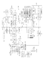
図3は第1実施形態に係るカメラ100のブロック図である。カメラ100にはユーザがこのカメラ100を使用するときに種々の操作を行なうための操作部120が設けられている。この操作部120には、カメラ100を作動させるための電源投入用の電源スイッチ121、オート撮影やマニュアル撮影等を選択するためのモードダイヤル123、各種のメニューの設定や選択あるいはズームを行なうための十字キー124、顔ボタン125、および十字キー124で選択されたメニューの実行やキャンセル等を行なうための情報位置指定キー126が備えられている。
FIG. 3 is a block diagram of the
また、カメラ100には、撮影画像や再生画像等を表示するための画像表示LCD102と、操作の手助けを行なうための操作LCD表示103が備えられている。
In addition, the
このカメラ100にはレリーズスイッチ104が配備されている。このレリーズスイッチ104によって撮影の開始指示がメインCPU20へと伝えられる。このカメラ100では所定のメニュー画面によって撮影と再生との切り替えが自在になっている。また、カメラ100には、コントラストAF時に被写体に投光スポットを照射するための発光ダイオード(LED)からなるAF補助光ランプ105b、閃光を発光するストロボ105aを有する閃光発光装置が配備されている。
The
また、カメラ100には、撮影レンズ101と、絞り131と、撮影レンズ101および絞り131を経由して結像された被写体像をアナログの画像信号に変換する撮像素子であるCCDセンサ132(以下CCD132と略記する)とが備えられている。CCD132は、CCD132に照射された被写体光により発生した電荷を可変の電荷蓄積時間(露光期間)の間蓄積することにより画像信号を生成するものである。CCD132からは、CG部136から出力される垂直同期信号VDに同期したタイミングでフレーム毎の画像信号が順次出力される。
In addition, the
撮像素子にCCD132を用いた場合には、色偽信号やモアレ縞等の発生を防止するために、入射光内の不要な高周波成分を除去する光学的ローパスフィルタ132aが配設されている。また、入射光内の赤外線を吸収若しくは反射して、長波長域で感度が高いCCDセンサ132固有の感度特性を補正する赤外カットフィルタ132bが配設されている。光学的ローパスフィルタ132a及び赤外カットフィルタ132bの具体的な配設の態様は特に限定されない。
When the
また、カメラ100には、CCDセンサ132からのアナログ画像信号が表わす被写体像のホワイトバランスを合わせるとともにその被写体像の階調特性における直線の傾き(γ)を調節し、さらにアナログ画像信号を増幅する増幅率可変の増幅器を含む白バランス・γ処理部133が備えられている。
The
さらに、カメラ100には、白バランス・γ処理部133からのアナログ信号をディジタルのR,G,B画像データにA/D変換するA/D変換部134と、そのA/D変換部134からのR,G,B画像データを格納するバッファメモリ135が備えられている。
Further, the
A/D変換部134によって得られたR,G,B画像データは、AF検出部150にも入力される。AF検出部150は、R,G,B画像データを1画面の所定の分割エリア毎にかつ同じ色成分毎に積算平均し、さらにフレームごとに、全エリアのR,G,B画像データの積算平均値Ir,Ig,Ibを算出する。この積算平均値Ir,Ig,IbをR,G,Bの可視光の受光量とする。
The R, G, B image data obtained by the A /
ただし、R,G,Bの可視光の受光量Ir,Ig,Ibは、R、G、Bの可視光にそれぞれ感度を有するCCD132以外の受光センサ(図示せず)によって検出することも可能である。
However, the R, G, and B visible light receiving amounts Ir, Ig, and Ib can be detected by a light receiving sensor (not shown) other than the
また、カメラ100には、CG(クロックジェネレータ)部136と、測光・測距用CPU137と、充電・発光制御部138と、通信制御部139と、YC処理部140と、電源電池68とが備えられている。
Further, the
CG部136は、CCDセンサ132を駆動するための垂直同期信号VD,高速掃き出しパルスPを含む駆動信号、白バランス・γ処理部133,A/D変換部134を制御する制御信号、および通信制御部139を制御する制御信号を出力する。また、このCG部136には、測光・測距用CPU137からの制御信号が入力される。
The
測光・測距用CPU137は、ズーム用モータ110、フォーカス用モータ111、絞り調節を行う絞り用モータ112を制御してズームレンズ101a、フォーカスレンズ101b、絞り131をそれぞれ駆動することにより被写体までの距離の算出(測距)を行ない、CG部136および充電・発光制御部138を制御する。ズーム用モータ110、フォーカス用モータ111、絞り用モータ112の駆動は、モータドライバ62によって制御され、モータドライバ62の制御コマンドは、測光・測距用CPU137あるいはメインCPU20から送られる。
The photometry / ranging
なお、ズームレンズ101a、フォーカスレンズ101b、絞り131、AF補助光照射角の駆動源は、ズーム用モータ110、フォーカス用モータ111、絞り用モータ112のような各種モータに限定する必然性はなく、アクチュエータなどであってもよい。
The driving source of the
測光・測距用CPU137は、レリーズスイッチ104が半押し(S1オン)されると、CCD132によって周期的(1/30秒から1/60秒ごと)に得られる画像データ(スルー画像)に基づいて被写体の明るさの測光(EV値の算出)を行う。
The
即ち、AE演算部151は、A/D変換部134から出力されたR、G、Bの画像信号を積算し、その積算値を測光・測距用CPU137に提供する。測光・測距用CPU137は、AE演算部151から入力する積算値に基づいて被写体の平均的な明るさ(被写体輝度)を検出し、撮影に適した露出値(EV値)を算出する。
That is, the
そして、測光・測距用CPU137は、得られたEV値に基づいて絞り131の絞り値(F値)及びCCD132の電子シャッタ(シャッタスピード)を含む露出値を所定のプログラム線図にしたがって決定する(AE動作)。
Then, the photometry / ranging
レリーズスイッチ104が全押し(S2オン)されると、測光・測距用CPU137は、その決定した絞り値に基づいて絞り131を駆動し、絞り131の開口径を制御するとともに、決定したシャッタスピードに基づき、CG136を介してCCD132での電荷蓄積時間を制御する。
When the
AE動作は、絞り優先AE,シャッタ速度優先AE,プログラムAEなどがあるが、いずれにおいても、被写体輝度を測定し、この被写体輝度の測光値に基づいて決められた露出値、すなわち絞り値とシャッタスピードとの組み合わせで撮影を行うことにより、適正な露光量で撮像されるように制御しており、面倒な露出決定の手間を省くことができる。 The AE operation includes an aperture priority AE, a shutter speed priority AE, a program AE, etc. In any case, the subject brightness is measured, and an exposure value determined based on the photometric value of the subject brightness, that is, an aperture value and a shutter. By taking a picture in combination with the speed, control is performed so that an image is taken with an appropriate exposure amount, and it is possible to save troublesome determination of exposure.
AF検出部150は、測光・測距CPU137により選定された検出範囲に対応する画像データをA/D変換部134から抽出する。焦点位置を検出する方法は、合焦位置で画像データの高周波成分が最大振幅になるという特徴を利用して行う。AF検出部150は、抽出された画像データの高周波成分を1フィールド期間積分することにより、振幅値を算出する。AF検出部150は、測光・測距CPU137がフォーカス用モータ111を駆動制御してフォーカスレンズ101bを可動範囲内、即ち無限遠側の端点(INF点)から至近側の端点(NEAR点)の間で移動させている間に順次振幅値の計算を実行し、最大振幅を検出した時に検出値を測光・測距CPU137に送信する。
The AF detection unit 150 extracts image data corresponding to the detection range selected by the photometry / ranging
測光・測距CPU137は、この検出値を取得して対応する合焦位置に、フォーカスレンズ101bを移動させるようにフォーカス用モータ111に指令を出す。フォーカス用モータ111は、測光・測距CPU137の指令に応じてフォーカスレンズ101bを合焦位置に移動させる(AF動作)。
The photometry / ranging
測光・測距用CPU137は、メインCPU20とのCPU間通信によってレリーズスイッチ104と接続されており、ユーザによりレリーズスイッチ104が半押しされた時に、この合焦位置の検出が行われる。また、測光・測距用CPU137には、ズーム用モータ110が接続されており、メインCPU20が、ズームスイッチ127によってユーザからのTELE方向又はWIDE方向へのズームの指令を取得した場合に、ズーム用モータ110を駆動させることにより、ズームレンズ101aをWIDE端とTELE端との間で移動させる。
The photometry / ranging
充電・発光制御部138は,ストロボ105aを発光させるために電源電池68からの電力の供給を受けて図示しない閃光発光用のコンデンサを充電したり、そのストロボ105aの発光を制御する。
The charging / light emission control unit 138 is supplied with electric power from the power supply battery 68 in order to cause the
充電・発光制御部138は,電源電池68の充電開始、レリーズスイッチ104の半押し・全押し操作信号等の各種の信号や、発光量、発光タイミングを示す信号をメインCPU20や測光・測距CPU137から取り込んだことに応じ、セルフタイマランプ(タリーランプ)105cやAF補助光ランプ105bへの電流供給制御を行い、所望の発光量が所望のタイミングで得られるように制御する。
The charging / light emission control unit 138 receives various signals such as a charging start of the power supply battery 68, a half-press / full-press operation signal of the
なお、セルフタイマランプ105cはLEDで構成してもよく、AF補助光ランプ105bを構成するLEDと共通にしてもよい。
Note that the self-
メインCPU20には、セルフタイマ回路83が接続されている。メインCPU20は、セルフ撮影モードが設定されている場合、レリーズスイッチ104の全押し信号に基づいて計時を行なう。この計時中に、メインCPU20は測光・測距CPU137を介し、残り時間に合わせて点滅速度をだんだんと早めながら、セルフタイマランプ105cを点滅させる。セルフタイマ回路83は、計時完了後に計時完了信号をメインCPU20に入力する。メインCPU20は、計時完了信号に基づいて、CCD132にシャッタ動作を実施させる。
A self-
通信制御部139には、通信ポート107が備えられており、この通信制御部139は、カメラ100により撮影された被写体の画像信号をUSB端子が備えられたパーソナルコンピュータ等の外部装置に出力し、およびこのような外部装置からカメラ100に画像信号を入力することにより、その外部装置との間のデータ通信を担うものである。また、このカメラ100は、ロール状の写真フイルムに写真撮影を行なう通常のカメラが有するISO感度80,100,200,400,1600等に切り替える機能を模擬した機能を有し、ISO感度400以上に切り替えられた場合、白バランス・γ処理部133の増幅器の増幅率が所定の増幅率を越えた高増幅率に設定された高感度モードとなる。通信制御部139は、高感度モードでの撮影中は、外部装置との通信を停止する。
The
また、カメラ100には、圧縮・伸長&ID抽出部143と、I/F部144が備えられている。圧縮・伸長&ID抽出部143は、バッファメモリ135に格納された画像データを、バスライン142を介して読み出して圧縮し、I/F部144を経由してメモリカード200に格納する。また、圧縮・伸長&ID抽出部143は、メモリカード200に格納された画像データの読み出しにあたり、メモリカード200固有の識別番号(ID)を抽出し、そのメモリカード200に格納された画像データを読み出して伸長し、バッファメモリ135に格納する。
The
バッファメモリ135に格納されたY/C信号は、圧縮・伸長&ID抽出部143によって所定のフォーマットに従って圧縮された後、I/F144を介してメモリカード200のようなリムーバブルメディアないしハードディスク(HDD)75のような内蔵型大容量記憶媒体に所定の形式(例えばExif(Exchangeable Image File Format)ファイル)で記録される。ハードディスク(HDD)75へのデータ記録またはハードディスク(HDD)75からのデータの読込みは、メインCPU20の指令に応じてハードディスクコントローラ74によって制御される。
The Y / C signal stored in the
また、カメラ100には、メインCPU20と、EEPROM146と、YC/RGB変換部147と、表示用のドライバ148とが備えられている。メインCPU20は、このカメラ100全体の制御を行なう。EEPROM146には、このカメラ100固有の固体データやプログラム等が格納されている。YC/RGB変換部147は、YC処理部140で生成されたカラー映像信号YCを3色のRGB信号に変換して表示用のドライバ148を経由して画像表示LCD102に出力する。
The
また、カメラ100は、AC電源から電力を得るためのACアダプタ48と電源電池68とが着脱可能な構成となっている。電源電池68は充電可能な二次電池、例えばニカド電池、ニッケル水素電池、リチウムイオン電池で構成される。電源電池68は使い切り型の一次電池、例えばリチウム電池、アルカリ電池で構成してもよい。電源電池68は図示しない電池収納室に装填することにより、カメラ100の各回路と電気的に接続される。
In addition, the
ACアダプタ48がカメラ100に装填されAC電源からACアダプタ48を介してカメラ100に電力が供給される場合には、電源電池68が電池収納室に装填されている場合であっても、優先的に当該ACアダプタ48から出力された電力がカメラ100の各部に駆動用の電力として供給される。また、ACアダプタ48が装填されておらず、かつ電源電池68が電池収納室に装填されている場合には、当該電源電池68から出力された電力がカメラ100の各部に駆動用の電力として供給される。
When the
なお、図示しないが、カメラ100には、電池収納室内に収納される電源電池68とは別にバックアップ電池が設けられている。内蔵バックアップ電池には例えば専用の二次電池が用いられ、電源電池68によって充電される。バックアップ電池は、電源電池68の交換や取り外し等、電源電池68が電池収納室に装填されていない場合、カメラ100の基本機能に給電する。
Although not shown, the
即ち、電源電池68又はACアダプタ48からの電源供給が停止すると、バックアップ電池がスイッチング回路(図示せず)によってRTC15等に接続され、これらの回路に給電する。これにより、バックアップ電池29が寿命に達しない限り、RTC15等の基本機能には、電源供給が間断なく継続する。
That is, when the power supply from the power supply battery 68 or the
RTC(Real Time Clock)15は計時専用のチップであり、電源電池68やACアダプタ48からの給電がオフされていてもバックアップ電池から電源供給を受けて継続的に動作する。
An RTC (Real Time Clock) 15 is a chip dedicated to timekeeping, and continuously operates by receiving power supply from the backup battery even when power supply from the power supply battery 68 or the
画像表示LCD102には透過型又は半透過型の液晶パネル71を背面側から照明するバックライト70が配設されており、省電力モードの場合には、メインCPU20によりそのバックライト70の明るさ(輝度)がバックライトドライバ72を介して制御され、バックライト70の消費電力が低減されるようになっている。また、省電力モードは、操作部120の情報位置指定キー126を押して画像表示LCD102にメニュー画面を表示させ、そのメニュー画面で所定の操作を行うことによってオン/オフを設定することができるようになっている。
The
図4は第1実施形態に係るメインCPU20の実行するプログラムをブロック図で概念的に示している。メインCPU20は、EEPROM146やハードディスク75等のコンピュータ読み取り可能な記憶媒体に記憶されたプログラムである顔情報検出部20a、撮影制御部20b、表示制御部20cをRAM145等に読み出して実行する。これらをまとめて単にプログラムと呼ぶこともある。
FIG. 4 conceptually shows a program executed by the
顔情報検出部20aは、メモリカード200から読み出された画像、あるいはバッファメモリ135に逐次記憶されるスルー画像から、人物の顔部分を含む領域である顔領域を検出する。顔領域の検出方法としては、例えば本出願人による特開平9−101579号公報において開示された技術を適用することができる。
The face
この技術は、撮影した画像の各画素の色相が肌色の範囲に含まれるか否かを判定して肌色領域と非肌色領域とに分割すると共に、画像中のエッジを検出して画像中の各箇所をエッジ部分又は非エッジ部分に分類する。そして、肌色領域内に位置し非エッジ部分に分類された画素からなり、かつエッジ部分と判定された画素で囲まれた領域を顔候補領域として抽出し、抽出した顔候補領域が人物の顔に相当する領域かを判定し、この判定結果に基づき顔領域として検出するものである。また、この他に、特開2003−209683号公報や特開2002−199221号公報に記載される方法で顔領域を検出することもできる。 This technology determines whether or not the hue of each pixel of the captured image is included in the skin color range and divides it into a skin color region and a non-skin color region, and detects edges in the image to detect each pixel in the image. The location is classified as an edge portion or a non-edge portion. Then, an area surrounded by pixels that are located in the skin color area and classified as a non-edge part and surrounded by pixels that are determined to be edge parts is extracted as a face candidate area, and the extracted face candidate area becomes a human face. It is determined whether the region is a corresponding region, and is detected as a face region based on the determination result. In addition to this, a face region can also be detected by a method described in Japanese Patent Application Laid-Open Nos. 2003-209683 and 2002-199221.
また、顔情報検出部20aは、検出された顔領域の位置、サイズ、顔検出の確からしさ(精度)、垂直方向を基準とした顔領域の傾きの角度、検出された顔領域が正立すべき画像の回転方向(例えば、実質的に頭頂部が上、顎が下となるべき回転方向。以下単に回転方向で表す)、顔領域を基準とした所定のデフォルトの切り出し領域(後述するバストショット等)も検出する。顔領域、顔領域の位置、サイズ、顔検出の確からしさ、回転方向を、まとめて顔情報という。顔情報の検出は、例えば特開2005−285035号公報に記載の方法で行うことができる。顔情報検出部20aは、検出した顔情報をバッファメモリ135に記憶する。顔情報は画像ファイルのタグ情報として画像とともに記憶してもよい。
The face
撮影制御部20bは、レリーズスイッチ104の半押し・全押しに応じて、AF/AE等の撮影準備や、記録用の画像取得処理の制御を統括する。顔情報検出部20aが検出した顔領域についてAF/AEを行うようにしてもよい。
The
表示制御部20cは、ドライバ148に内蔵されたOSD信号発生回路148aに対し、シャッタ速度や絞り値、撮影可能枚数、撮影日時、警告メッセージ、グラフィカルユーザインターフェイス(GUI)等の文字及び記号情報を表示するための信号を発生させるコマンドを送る。OSD信号発生回路148aから出力される信号は、必要に応じてYC/RGB変換部147からの画像信号に混合されて、液晶パネル71に供給される。これにより、スルー画像や再生画像に文字等が合成された合成画像が表示される。
The
以下、図5のフローチャートを参照し、CPU20の実行する切り出し処理の流れを説明する。この処理は、操作部120による「画像再生モード」のオンに引き続く「トリミングモード」のオンに連動して開始する。S1〜3の処理は、「トリミングモード」がオフにされるまで繰り返される。なお、この処理は、「撮影モード」時に得られるスルー画像についても行うことができる(以下、「クイック拡大」と呼ぶこともある)。
Hereinafter, the flow of the clipping process executed by the
S1では、表示制御部20cは、メモリカード200から読み出した所望の画像を表示する(例えば図6の「1コマ全体画像」)。どの画像を表示するかは、操作部120から任意に選択できるものとする。
In S1, the
顔情報検出部20aは、表示された画像から顔情報の検出を行う。そして、顔情報検出部20aが少なくとも1つの顔情報を検出した場合、S2に移行する。
The face
なお、画像の表示時点で顔情報の検出を開始すると、迅速な画像表示処理に支障をきたすおそれがある。このため、「撮影モード設定」時に顔ボタン125が押された場合、その時点で顔情報の検出を行い、検出された顔情報を、記録用画像と対応づけて(例えば記録用画像のヘッダ情報やタグ情報として)メモリカード200に記録しておくとよい。そして、本ステップS1では、顔情報の検出を行う代わりに、表示された画像に対応づけられた顔情報の読み出しを試み、顔情報を読み出すことができたと判断されたことに応じ、S2に移行すればよい。
Note that if detection of face information is started at the time of image display, there is a risk of impeding rapid image display processing. For this reason, when the
S2では、表示制御部20cは、顔ボタン125の押下を検知したことに応じてS3に移行する。
In S2, the
S3では、表示制御部20cは、顔情報検出部20aの検出した顔情報に基づいて所定のデフォルト切り出し領域を確定し、確定された切り出し領域を、画像から切り出す。そして、切り出した領域をそのまま表示するか、あるいは所定の比率で拡大したり、フィット表示したりする(例えば図6の「顔拡大画像」)。
In S3, the
その後、さらに、周知のトリミング領域の任意設定と同様、十字キー124の操作に応じて、確定された切り出し領域の位置、サイズ、画角、倍率を任意の値に変更することもできる。切り出し領域の変更を指示するGUIの表示方法は任意であり、変更された切り出し領域そのものをプレビュー表示してもよいし、画像の表示はそのまま変更せず、切り出し領域を示す枠などの映像を画像に重畳して表示させ、十字キー124の操作に応じてこの枠を拡縮移動させることで切り出し領域を変更してもよい。
Thereafter, as in the known arbitrary setting of the trimming area, the position, size, angle of view, and magnification of the determined cutout area can be changed to arbitrary values in accordance with the operation of the
このように、本実施形態では、顔領域を基準とした所定のデフォルトの切り出し領域を表示し、その後に任意の切り出し領域の変更を受け付ける。従って、従来と異なり、初めからユーザが切り出し領域を設定しなくて済み、人物画像・顔領域を中心としたトリミングの領域を簡単に設定することができ、顔部分にズーム枠をいちいち移動させるなどの手間を省ける。 As described above, in the present embodiment, a predetermined default cutout area based on the face area is displayed, and then any change of the cutout area is accepted. Therefore, unlike the conventional case, the user does not need to set the clipping region from the beginning, the trimming region centering on the person image / face region can be easily set, and the zoom frame is moved to the face portion, etc. Can save you the trouble.
切り出し領域の確定は、例えば次のようにして行う。 The cutout area is determined as follows, for example.
図7に例示するように、顔領域の縦サイズをα(単位はピクセル等)であり、かつ回転方向が0度とした場合、まず、切り出し領域の縦サイズをβ=4α、切り出し領域の横サイズをγ=4β/3と確定する。次に、顔領域の中心座標(x,y)と同一の座標(x,y)を切り出し領域の中心とし、縦サイズをβ、横サイズをγとする領域を切り出し領域と確定する。なお、回転方向が180度の場合は、回転方向が0度の場合と同様にして切り出し領域を確定し、それを切り出した上で180度回転すればよい。 As illustrated in FIG. 7, when the vertical size of the face region is α (the unit is pixels or the like) and the rotation direction is 0 degree, first, the vertical size of the cutout region is β = 4α, and the horizontal size of the cutout region is Determine the size as γ = 4β / 3. Next, a region having the same coordinate (x, y) as the center coordinate (x, y) of the face region as the center of the cutout region, the vertical size being β, and the horizontal size being γ is determined as the cutout region. If the rotation direction is 180 degrees, the cutout area is determined in the same manner as in the case where the rotation direction is 0 degree, and the cutout area is cut out and then rotated 180 degrees.
あるいは、回転方向が270度の場合、まず、切り出し領域の縦サイズをβ=3α、切り出し領域の横サイズをγ=4β/3と確定する。次に、顔領域の中心座標(x,y)と同一の座標(x,y)を切り出し領域の中心とし、縦サイズをβ、横サイズをγとする領域を切り出し領域と確定する。なお、回転方向が90度の場合は、回転方向が0度の場合と同様にして切り出し領域を確定し、それを切り出した上で90度回転すればよい。 Alternatively, when the rotation direction is 270 degrees, first, the vertical size of the cutout area is determined as β = 3α, and the horizontal size of the cutout area is determined as γ = 4β / 3. Next, a region having the same coordinate (x, y) as the center coordinate (x, y) of the face region as the center of the cutout region, the vertical size being β, and the horizontal size being γ is determined as the cutout region. When the rotation direction is 90 degrees, the cutout area is determined in the same manner as in the case where the rotation direction is 0 degrees, and the cutout area is cut out and then rotated by 90 degrees.
また、顔領域に基づいてマージンを確定してもよく、例えば、マージンδ=所定の比率(0〜1.0)×αとすればよい。マージンδは、切り出し領域の縦横サイズと元の撮影画像のサイズとが、ほぼ同一の場合、切り出し処理の意味がないから、これを抑制するための定数である。例えば、図8のような切り出し領域が確定された場合は、切り出し処理を行わなくてよい。 Further, the margin may be determined based on the face area, for example, margin δ = predetermined ratio (0 to 1.0) × α. The margin δ is a constant for suppressing the cut-out process when the vertical and horizontal sizes of the cut-out area and the size of the original captured image are substantially the same, since there is no meaning of the cut-out process. For example, when the cutout area as shown in FIG. 8 is determined, the cutout process need not be performed.
また、1つの画像から複数の顔情報が検出された場合は、顔の確からしさが最も高い顔情報、あるいは顔領域のサイズが最も大きい顔情報など、所定の優先度の指標が最も高い顔情報に基づいて、所定の切り出し領域を確定してもよい。 In addition, when a plurality of pieces of face information are detected from one image, face information having the highest predetermined priority index, such as face information having the highest likelihood of a face or face information having the largest face area size. Based on the above, a predetermined cutout area may be determined.
<第2実施形態>
第1実施形態では、検出された個々の顔領域の1つだけを基準にデフォルトの切り出し領域が確定されていた。しかし、顔領域が複数検出された場合は、全ての顔領域が含まれる範囲でデフォルトの切り出し領域を確定してもよい。
Second Embodiment
In the first embodiment, the default cutout area is determined based on only one of the detected individual face areas. However, when a plurality of face areas are detected, the default cutout area may be determined within a range including all face areas.
すなわち、図9に例示するように、3つ、7つ、あるいは2つ等、複数の顔領域が検出された場合、いずれの場合においても、1つの画像中の複数の顔領域すべてを包含する領域がデフォルトの切り出し領域となるよう、切り出し領域の座標および縦横サイズを確定し、確定された切り出し領域を画像から切り出すとよい。 That is, as illustrated in FIG. 9, when a plurality of face regions such as three, seven, or two are detected, all the plurality of face regions in one image are included in any case. The coordinates and vertical / horizontal sizes of the cutout area are determined so that the area becomes the default cutout area, and the determined cutout area is cut out from the image.
こうすると、全員の顔が画角に入ったトリミングを容易に行うことができ、集合写真のトリミングなどには特に効果を発揮する。 In this way, it is possible to easily perform trimming in which all the faces are included in the angle of view, and this is particularly effective for trimming a group photo.
<第3実施形態>
第2実施形態では、検出された複数の顔領域のすべてを包含するような切り出し領域を確定していたが、ユーザの指示に応じて個々の顔を1つずつ選択し、選択された1つの顔領域を基準として順次切り出し領域を確定し、その切り出し領域を順次切り出して表示してもよい。
<Third Embodiment>
In the second embodiment, a cutout region that includes all of the detected plurality of face regions is fixed. However, according to a user instruction, each face is selected one by one, and one selected face is selected. The cutout area may be determined sequentially with reference to the face area, and the cutout area may be cut out and displayed sequentially.
例えば図10に示すように、1つの画像中に3人分の顔領域が検出された場合、いずれか1つの顔領域を十字ボタン124の左右キーの押下あるいは顔ボタン125の連続押下応じた顔検出枠(あるいはカーソル)の移動によって選択可能にし、選択された1つの顔領域を基準に、第1実施形態と同様にしてデフォルトの切り出し領域を確定し、その領域を切り出して順次表示してもよい。
For example, as shown in FIG. 10, when face areas for three people are detected in one image, any one of the face areas is detected by pressing the left / right key of the
<第4実施形態>
第1〜3実施形態において、(1)顔領域のサイズが大きすぎて切り出し領域のサイズが撮影画像サイズを超えてしまう場合、(2)切り出し領域を拡大すると撮影画像サイズそのものを超えてしまう場合、(3)顔が小さく、切り出し領域のサイズが所定のサイズ(例えばVGA)に満たない場合は、次のように処理すればよい。
<Fourth embodiment>
In the first to third embodiments, (1) when the size of the face area is too large and the size of the cutout area exceeds the captured image size, and (2) when the cutout area is enlarged, the size of the captured image itself is exceeded. (3) When the face is small and the size of the cut-out area is less than a predetermined size (for example, VGA), the following processing may be performed.
(1)顔領域のサイズが大きすぎて切り出し領域のサイズが撮影画像サイズを超えてしまう場合(図7の(1)式を満たさない、すなわちβ≧ py - δの場合)
下記の条件までは、第1実施形態と同様の切り出し処理(顔位置に応じたズーム倍率/位置アシストのこと。以下「トリミング・アシスト」という)を行う。顔を中心としてβをαの2倍までとし、切り出し領域はそれ以下に縮小しない。
(1) When the size of the face area is too large and the size of the cutout area exceeds the captured image size (when the expression (1) in FIG. 7 is not satisfied, that is, β ≧ py−δ)
Up to the following conditions, the same clipping process as in the first embodiment (zoom magnification / position assist according to face position; hereinafter referred to as “trimming assist”) is performed. With the face as the center, β is set to be twice as large as α, and the cut-out area is not reduced below that.
横撮り( 0,180度) … 4α≧β≧ 2α
縦撮り(90,270度) … 3α≧β≧ 2α
検出された顔のサイズが大きく(画像短辺の1/1.2 〜 1/2.0)、β< 2αとなってしまう場合は、トリミング・アシストは行わない。これは、トリミング位置と倍率をアシストする機能であるため、画面全体が顔で占められては意味を成さないから、2倍までという制限を設けている。画面全体で顔領域の占める割合が多い場合のみとなる(画像短辺の1/1.2 〜 1/2.0)。
Horizontal shooting (0,180 degrees)… 4α ≧ β ≧ 2α
Vertical shooting (90,270 degrees)… 3α ≧ β ≧ 2α
If the detected face size is large (1 / 1.2 to 1 / 2.0 of the short side of the image) and β <2α, trimming assist is not performed. This is a function that assists the trimming position and magnification, so it does not make sense if the entire screen is occupied by a face, so there is a limit of up to twice. Only when the face area occupies a large proportion of the entire screen (1 / 1.2 to 1 / 2.0 of the short side of the image).
なお、「画像再生モード」のオンから「トリミングモード」がオフのまま、顔ボタン125が押された場合、あるいは「撮影モード」のオンのときに顔ボタン125が押された場合、トリミング時と同等の処理を行うことができる(クイック拡大)。ただし、クイック拡大では、βをαまでとし、切り出し領域はそれ以下に縮小しない。これは顔の表情やピント確認が主な目的となるため、2倍という制限は設けない。しかしながら、例えば、鼻面だけを拡大しても意味はないため、1倍という制限は設ける。
When the
横撮り( 0,180度) … 4α≧β≧ α
縦撮り(90,270度) … 3α≧β≧ α
(2)切り出し範囲が撮影画像をはみ出す場合(図7の(2),(3)式の条件外の場合)
トリミング/クイック拡大共に、切り出し範囲が元画像をはみ出す場合は、図11のように、顔領域の中心と同一の座標を切り出し領域の中心とすることを放棄し、切り出し範囲が画像をはみ出さないようにする。
Horizontal shooting (0,180 degrees)… 4α ≧ β ≧ α
Vertical shooting (90,270 degrees)… 3α ≧ β ≧ α
(2) When the cut-out range protrudes the captured image (when the condition is outside the conditions of equations (2) and (3) in FIG. 7)
In both the trimming / quick enlargement, when the cutout area protrudes from the original image, the same coordinates as the center of the face area are abandoned as shown in FIG. 11, and the cutout area does not protrude from the image. Like that.
(3)顔が小さく、切り出し領域のサイズが所定のサイズ(例えばVGA)に満たない場合(β< 480)
バストショット構図を構成しても切り出しサイズがVGA以下となってしまう場合は、切り出しサイズをVGAになるようにしなくてはならないため、顔垂直方向で下に向けて切り出し領域を拡大する。下に拡大することで、バストショット → ウエストショット(腰上) → ニーショット(膝上) → フルフィギュア(全身)となるようにする。元画像の端に切り出し範囲が到達した場合は、顔垂直方向で下端のときは上方に、左右端の場合は逆方に拡大する(VGA以上の大きさで切り出し不可の場合と同等。下方向に拡大しているため、顔中心はもともと破棄されている)。
(3) When the face is small and the size of the cutout area is less than a predetermined size (for example, VGA) (β <480)
If the cutout size becomes VGA or less even if the bust shot composition is configured, the cutout area is enlarged downward in the vertical direction of the face because the cutout size must be VGA. By enlarging down, bust shot → waist shot (waist up) → knee shot (on knee) → full figure (whole body). When the cut-out range reaches the edge of the original image, the face is vertically expanded at the lower end, and expanded at the left and right ends in the opposite direction (equivalent to a VGA or larger size that cannot be clipped down. The center of the face was originally discarded).
この条件は、撮影サイズが0.3M超 〜 横撮り:1920x1440(縦撮り:2560x1920)であり、且つ検出された顔サイズが小さい場合のみとなる(例えば、1/12)。 This condition is only when the shooting size is greater than 0.3M to horizontal shooting: 1920x1440 (vertical shooting: 2560x1920) and the detected face size is small (for example, 1/12).
なお、図13は最小の切り出し領域の一例、図14は最小のクイック拡大領域の一例を示す。 FIG. 13 shows an example of the minimum cutout area, and FIG. 14 shows an example of the minimum quick enlargement area.
20:メインCPU、20a:顔情報検出部、20b:撮影制御部、20c:表示制御部、83:セルフタイマ回路、101:撮影レンズ、105c:セルフタイマランプ、125:顔ボタン、132:CCD、134:A/D変換部、150:AF検出部、151:AE演算部 20: Main CPU, 20a: Face information detection unit, 20b: Shooting control unit, 20c: Display control unit, 83: Self-timer circuit, 101: Shooting lens, 105c: Self-timer lamp, 125: Face button, 132: CCD, 134: A / D conversion unit, 150: AF detection unit, 151: AE calculation unit
Claims (11)
前記読み出した元画像に基づいて画像を表示する表示手段と、
前記表示手段に表示された画像に対して手動操作によって任意のトリミング範囲を指示する手動トリミング指示手段と、
前記読み出した元画像が人物の顔画像を含んでいる場合に、手動操作時に顔画像を含んだ所定のトリミング範囲を自動的に指示する自動トリミング指示手段と、
前記手動トリミング指示手段、又は自動トリミング指示手段によって指示されたトリミング範囲内の画像を、前記表示手段に表示された画像の元画像から切り出すトリミング手段と、
を備え、
前記自動トリミング指示手段は、前記所定のトリミング範囲としてバストショットサイズを指示すると、前記所定のトリミング範囲の縦サイズをβ、前記元画像の縦サイズをpy、マージンをδとした場合、β≧py-δを満たすが、前記所定のトリミング範囲の縦サイズが前記顔画像の縦サイズの2倍以上であれば、前記所定のトリミング範囲の中心を前記顔画像の中心にして前記所定のトリミング範囲を自動的に指示することを特徴とする画像トリミング装置。 Reading means for reading out the original image to be trimmed from the recording means in which the original image is recorded;
Display means for displaying an image based on the read original image;
Manual trimming instruction means for instructing an arbitrary trimming range by manual operation with respect to the image displayed on the display means;
Automatic trimming instruction means for automatically instructing a predetermined trimming range including a face image at the time of manual operation when the read original image includes a human face image;
Trimming means for cutting out an image within the trimming range designated by the manual trimming instruction means or the automatic trimming instruction means from an original image of the image displayed on the display means;
With
When the automatic trimming instruction means designates a bust shot size as the predetermined trimming range, β ≧ py when the vertical size of the predetermined trimming range is β, the vertical size of the original image is py, and the margin is δ. -δ is satisfied, but if the vertical size of the predetermined trimming range is at least twice the vertical size of the face image, the predetermined trimming range is set with the center of the predetermined trimming range being the center of the face image. An image trimming apparatus characterized by automatically instructing.
Priority Applications (3)
| Application Number | Priority Date | Filing Date | Title |
|---|---|---|---|
| JP2006202608A JP4683339B2 (en) | 2006-07-25 | 2006-07-25 | Image trimming device |
| US11/782,436 US8116535B2 (en) | 2006-07-25 | 2007-07-24 | Image trimming apparatus |
| CNA2007101297674A CN101132480A (en) | 2006-07-25 | 2007-07-25 | Image trimming apparatus |
Applications Claiming Priority (1)
| Application Number | Priority Date | Filing Date | Title |
|---|---|---|---|
| JP2006202608A JP4683339B2 (en) | 2006-07-25 | 2006-07-25 | Image trimming device |
Publications (3)
| Publication Number | Publication Date |
|---|---|
| JP2008027401A JP2008027401A (en) | 2008-02-07 |
| JP2008027401A5 JP2008027401A5 (en) | 2010-11-11 |
| JP4683339B2 true JP4683339B2 (en) | 2011-05-18 |
Family
ID=38986337
Family Applications (1)
| Application Number | Title | Priority Date | Filing Date |
|---|---|---|---|
| JP2006202608A Active JP4683339B2 (en) | 2006-07-25 | 2006-07-25 | Image trimming device |
Country Status (3)
| Country | Link |
|---|---|
| US (1) | US8116535B2 (en) |
| JP (1) | JP4683339B2 (en) |
| CN (1) | CN101132480A (en) |
Families Citing this family (45)
| Publication number | Priority date | Publication date | Assignee | Title |
|---|---|---|---|---|
| TWI378723B (en) * | 2008-02-01 | 2012-12-01 | Mstar Semiconductor Inc | Multimedia system and remote controller thereof |
| JP5116513B2 (en) * | 2008-03-10 | 2013-01-09 | キヤノン株式会社 | Image display apparatus and control method thereof |
| US8711265B2 (en) | 2008-04-24 | 2014-04-29 | Canon Kabushiki Kaisha | Image processing apparatus, control method for the same, and storage medium |
| JP4974966B2 (en) * | 2008-05-19 | 2012-07-11 | キヤノン株式会社 | Image editing apparatus, control method therefor, and program |
| JP5164692B2 (en) * | 2008-06-27 | 2013-03-21 | キヤノン株式会社 | Image processing apparatus, image processing method, and program |
| JP5189913B2 (en) * | 2008-07-14 | 2013-04-24 | イーストマン コダック カンパニー | Image processing device |
| JP5312256B2 (en) * | 2008-09-12 | 2013-10-09 | 三洋電機株式会社 | Imaging apparatus and imaging system |
| KR20100058280A (en) * | 2008-11-24 | 2010-06-03 | 삼성전자주식회사 | Method and apparatus for taking images using portable terminal |
| US20100214321A1 (en) * | 2009-02-24 | 2010-08-26 | Nokia Corporation | Image object detection browser |
| CN102036003B (en) * | 2009-09-30 | 2012-07-18 | 佛山普立华科技有限公司 | Digital camera system and certificate photo shooting method thereof |
| JP2011166409A (en) * | 2010-02-09 | 2011-08-25 | Panasonic Corp | Motion-recognizing remote-control receiving device, and motion-recognizing remote-control control method |
| JP4986189B2 (en) | 2010-03-31 | 2012-07-25 | カシオ計算機株式会社 | Imaging apparatus and program |
| JP5447183B2 (en) * | 2010-05-21 | 2014-03-19 | フリュー株式会社 | Photo sticker creation apparatus and method, and program |
| JP5264831B2 (en) | 2010-06-21 | 2013-08-14 | シャープ株式会社 | Image processing apparatus, image reading apparatus, image forming apparatus, image processing method, computer program, and recording medium |
| US20120257072A1 (en) | 2011-04-06 | 2012-10-11 | Apple Inc. | Systems, methods, and computer-readable media for manipulating images using metadata |
| US8988512B2 (en) | 2011-04-14 | 2015-03-24 | Mediatek Inc. | Method for adjusting playback of multimedia content according to detection result of user status and related apparatus thereof |
| CN102790857A (en) * | 2011-05-19 | 2012-11-21 | 华晶科技股份有限公司 | Image processing method |
| TW201249191A (en) * | 2011-05-19 | 2012-12-01 | Altek Corp | Method for processing image |
| JP5963006B2 (en) * | 2011-07-25 | 2016-08-03 | パナソニックIpマネジメント株式会社 | Image conversion apparatus, camera, video system, image conversion method, and recording medium recording program |
| KR101795601B1 (en) | 2011-08-11 | 2017-11-08 | 삼성전자주식회사 | Apparatus and method for processing image, and computer-readable storage medium |
| US9008436B2 (en) | 2011-10-28 | 2015-04-14 | Intellectual Ventures Fund 83 Llc | Image recomposition from face detection and facial features |
| US9025836B2 (en) * | 2011-10-28 | 2015-05-05 | Intellectual Ventures Fund 83 Llc | Image recomposition from face detection and facial features |
| US8811747B2 (en) | 2011-10-28 | 2014-08-19 | Intellectual Ventures Fund 83 Llc | Image recomposition from face detection and facial features |
| US9025835B2 (en) | 2011-10-28 | 2015-05-05 | Intellectual Ventures Fund 83 Llc | Image recomposition from face detection and facial features |
| US8938100B2 (en) | 2011-10-28 | 2015-01-20 | Intellectual Ventures Fund 83 Llc | Image recomposition from face detection and facial features |
| WO2013069048A1 (en) | 2011-11-07 | 2013-05-16 | 株式会社ソニー・コンピュータエンタテインメント | Image generating device and image generating method |
| WO2013069050A1 (en) | 2011-11-07 | 2013-05-16 | 株式会社ソニー・コンピュータエンタテインメント | Image generation device and image generation method |
| US10284776B2 (en) * | 2011-11-07 | 2019-05-07 | Sony Interactive Entertainment Inc. | Image generation apparatus and image generation method |
| US9560274B2 (en) | 2011-11-07 | 2017-01-31 | Sony Corporation | Image generation apparatus and image generation method |
| JP2013153375A (en) * | 2012-01-26 | 2013-08-08 | Sony Corp | Image processing apparatus, image processing method, and recording medium |
| CN102982568B (en) * | 2012-11-12 | 2015-12-16 | 东莞宇龙通信科技有限公司 | A kind of method of automatic cutting image and device |
| US10178298B2 (en) | 2012-12-20 | 2019-01-08 | Sony Corporation | Image processing device, image processing method, and recording medium for optimal trimming of a captured image |
| KR101999137B1 (en) | 2013-01-03 | 2019-07-11 | 삼성전자주식회사 | Apparatus and method for processing an image in device having an camera |
| CN104836978B (en) * | 2014-03-10 | 2019-01-22 | 腾讯科技(北京)有限公司 | The method and device of video processing |
| FR3030086A1 (en) * | 2014-12-16 | 2016-06-17 | Orange | CONTROLLING THE DISPLAY OF AN IMAGE REPRESENTATIVE OF A CAPTURED OBJECT BY A DEVICE FOR ACQUIRING IMAGES |
| CN104754217A (en) * | 2015-03-06 | 2015-07-01 | 深圳市欧珀通信软件有限公司 | Shooting method and terminal |
| CN104836957A (en) * | 2015-05-09 | 2015-08-12 | 陈包容 | Photo shooting processing method and device |
| CN105263049B (en) * | 2015-10-28 | 2019-10-29 | 努比亚技术有限公司 | A kind of video Scissoring device, method and mobile terminal based on frame coordinate |
| JP6902886B2 (en) * | 2017-03-14 | 2021-07-14 | キヤノン株式会社 | Image processing equipment, methods and programs |
| JP2019029998A (en) | 2017-07-28 | 2019-02-21 | キヤノン株式会社 | Imaging apparatus, control method of imaging apparatus and control program |
| CN107704292A (en) * | 2017-10-18 | 2018-02-16 | 维沃移动通信有限公司 | Picture method to set up and mobile terminal in a kind of application program |
| DE102020113972A1 (en) * | 2019-05-31 | 2020-12-03 | Apple Inc. | VIDEO ANALYSIS AND MANAGEMENT TECHNIQUES FOR MEDIA ACQUISITION AND STORAGE |
| CN110706150A (en) * | 2019-07-12 | 2020-01-17 | 北京达佳互联信息技术有限公司 | Image processing method, image processing device, electronic equipment and storage medium |
| CN110568982B (en) * | 2019-09-12 | 2021-04-20 | 北京字节跳动网络技术有限公司 | Picture clipping method and device in online presentation, storage medium and equipment |
| JP7392368B2 (en) | 2019-10-03 | 2023-12-06 | 富士フイルムビジネスイノベーション株式会社 | Image processing device, system, program |
Citations (5)
| Publication number | Priority date | Publication date | Assignee | Title |
|---|---|---|---|---|
| JP2000036032A (en) * | 1998-07-17 | 2000-02-02 | Fujitsu Ltd | Foreground picture extracting method, picture processor, automatic trimming device, recording medium and portrait picture device |
| JP2003319169A (en) * | 2002-04-26 | 2003-11-07 | Fuji Photo Film Co Ltd | Image processing method |
| JP2004005384A (en) * | 2002-04-19 | 2004-01-08 | Sony Corp | Image processing method, image processing device, program, recording medium, automatic trimming device and picture-taking arrangement |
| JP2004096486A (en) * | 2002-08-30 | 2004-03-25 | Sony Corp | Image extracting apparatus, method therefor, and imaging apparatus |
| JP2004096487A (en) * | 2002-08-30 | 2004-03-25 | Sony Corp | Image processing apparatus, method therefor and imaging apparatus |
Family Cites Families (27)
| Publication number | Priority date | Publication date | Assignee | Title |
|---|---|---|---|---|
| JP3516786B2 (en) | 1995-10-05 | 2004-04-05 | 富士写真フイルム株式会社 | Face area extraction method and copy condition determination method |
| JP3436473B2 (en) * | 1997-06-20 | 2003-08-11 | シャープ株式会社 | Image processing device |
| US6907136B1 (en) * | 1999-05-19 | 2005-06-14 | Canon Kabushiki Kaisha | Image processing of designated image portion |
| DE60045044D1 (en) * | 1999-09-14 | 2010-11-11 | Topcon Corp | Face photographing apparatus and method |
| US7127087B2 (en) * | 2000-03-27 | 2006-10-24 | Microsoft Corporation | Pose-invariant face recognition system and process |
| JP3983469B2 (en) * | 2000-11-14 | 2007-09-26 | 富士フイルム株式会社 | Image processing apparatus, method, and recording medium |
| JP2002199221A (en) | 2000-12-27 | 2002-07-12 | Fuji Photo Film Co Ltd | Density correction curve generating device and method |
| US7034848B2 (en) * | 2001-01-05 | 2006-04-25 | Hewlett-Packard Development Company, L.P. | System and method for automatically cropping graphical images |
| WO2002103634A1 (en) * | 2001-06-15 | 2002-12-27 | Datacard Corporation | Apparatus and method for machine vision |
| US20030044083A1 (en) * | 2001-09-04 | 2003-03-06 | Tsuyoshi Mekata | Image processing apparatus, image processing method, and image processing program |
| US7324246B2 (en) * | 2001-09-27 | 2008-01-29 | Fujifilm Corporation | Apparatus and method for image processing |
| JP2003209683A (en) | 2001-09-27 | 2003-07-25 | Fuji Photo Film Co Ltd | Image processing equipment and image processing method |
| WO2004036900A1 (en) | 2002-08-30 | 2004-04-29 | Sony Corporation | Image extraction device, image extraction method, image processing device, image processing method, and imaging device |
| JP4009163B2 (en) | 2002-08-30 | 2007-11-14 | 富士通株式会社 | Object detection apparatus, object detection method, and object detection program |
| GB2395852B (en) * | 2002-11-29 | 2006-04-19 | Sony Uk Ltd | Media handling system |
| JP3690391B2 (en) | 2003-01-23 | 2005-08-31 | セイコーエプソン株式会社 | Image editing apparatus, image trimming method, and program |
| JP4406547B2 (en) * | 2003-03-03 | 2010-01-27 | 富士フイルム株式会社 | ID card creation device, ID card, face authentication terminal device, face authentication device and system |
| US20050031173A1 (en) * | 2003-06-20 | 2005-02-10 | Kyungtae Hwang | Systems and methods for detecting skin, eye region, and pupils |
| JP2005084980A (en) * | 2003-09-09 | 2005-03-31 | Fuji Photo Film Co Ltd | Data generation unit for card with face image, method and program |
| CN1599406A (en) * | 2003-09-09 | 2005-03-23 | 富士胶片株式会社 | Image processing method and device and its program |
| JP4177779B2 (en) | 2004-03-31 | 2008-11-05 | 富士フイルム株式会社 | Image display control device and method, and program for controlling image display control device |
| JP2006086732A (en) * | 2004-09-15 | 2006-03-30 | Fuji Photo Film Co Ltd | Image processor and image processing method |
| JP2006254229A (en) * | 2005-03-11 | 2006-09-21 | Fuji Photo Film Co Ltd | Imaging apparatus, imaging method and imaging program |
| JP4538386B2 (en) * | 2005-07-06 | 2010-09-08 | 富士フイルム株式会社 | Target image recording apparatus, imaging apparatus, and control method thereof |
| JP4730667B2 (en) * | 2006-07-25 | 2011-07-20 | 富士フイルム株式会社 | Automatic regeneration method and apparatus |
| JP4998995B2 (en) * | 2007-06-08 | 2012-08-15 | 富士フイルム株式会社 | Album creating apparatus and method, and program |
| JP4850818B2 (en) * | 2007-11-30 | 2012-01-11 | キヤノン株式会社 | Image processing apparatus and method |
-
2006
- 2006-07-25 JP JP2006202608A patent/JP4683339B2/en active Active
-
2007
- 2007-07-24 US US11/782,436 patent/US8116535B2/en active Active
- 2007-07-25 CN CNA2007101297674A patent/CN101132480A/en active Pending
Patent Citations (5)
| Publication number | Priority date | Publication date | Assignee | Title |
|---|---|---|---|---|
| JP2000036032A (en) * | 1998-07-17 | 2000-02-02 | Fujitsu Ltd | Foreground picture extracting method, picture processor, automatic trimming device, recording medium and portrait picture device |
| JP2004005384A (en) * | 2002-04-19 | 2004-01-08 | Sony Corp | Image processing method, image processing device, program, recording medium, automatic trimming device and picture-taking arrangement |
| JP2003319169A (en) * | 2002-04-26 | 2003-11-07 | Fuji Photo Film Co Ltd | Image processing method |
| JP2004096486A (en) * | 2002-08-30 | 2004-03-25 | Sony Corp | Image extracting apparatus, method therefor, and imaging apparatus |
| JP2004096487A (en) * | 2002-08-30 | 2004-03-25 | Sony Corp | Image processing apparatus, method therefor and imaging apparatus |
Also Published As
| Publication number | Publication date |
|---|---|
| CN101132480A (en) | 2008-02-27 |
| US8116535B2 (en) | 2012-02-14 |
| US20080025558A1 (en) | 2008-01-31 |
| JP2008027401A (en) | 2008-02-07 |
Similar Documents
| Publication | Publication Date | Title |
|---|---|---|
| JP4683339B2 (en) | Image trimming device | |
| JP4654974B2 (en) | Imaging apparatus and imaging method | |
| JP4626425B2 (en) | Imaging apparatus, imaging method, and imaging program | |
| JP4943769B2 (en) | Imaging apparatus and in-focus position search method | |
| US8111315B2 (en) | Imaging device and imaging control method that detects and displays composition information | |
| JP4661413B2 (en) | Imaging apparatus, number of shots management method and number of shots management program | |
| JP4644883B2 (en) | Imaging device | |
| JP4574459B2 (en) | Image capturing apparatus, control method therefor, program, and storage medium | |
| JP4683228B2 (en) | Image display device, photographing device, image display method and program | |
| JP2008131094A (en) | Imaging apparatus and method | |
| JP4623299B2 (en) | Imaging apparatus and imaging method | |
| US20070268397A1 (en) | Image pickup apparatus and image pickup control method | |
| JP4144144B2 (en) | Image recording method and apparatus | |
| JP2007104108A (en) | Imaging apparatus, emission luminance control method and program | |
| JP4697604B2 (en) | Imaging apparatus and imaging control method | |
| JP2007274598A (en) | Imaging apparatus and photographing condition display method | |
| JP5134116B2 (en) | Imaging apparatus and in-focus position search method | |
| JP2008129082A (en) | Image taking device and light emission control method | |
| JP2008022280A (en) | Imaging apparatus, method, and program | |
| JP2007178453A (en) | Imaging apparatus and imaging method | |
| JP6289068B2 (en) | Imaging apparatus and control method thereof | |
| JP2007295390A (en) | Imaging apparatus, and warning method | |
| JP2006352252A (en) | Image recorder, image recording/reproducing method and program | |
| JP4808918B2 (en) | Imaging device | |
| JP2007072668A (en) | Optical operation device |
Legal Events
| Date | Code | Title | Description |
|---|---|---|---|
| A621 | Written request for application examination |
Free format text: JAPANESE INTERMEDIATE CODE: A621 Effective date: 20090224 |
|
| A521 | Request for written amendment filed |
Free format text: JAPANESE INTERMEDIATE CODE: A523 Effective date: 20100928 |
|
| A871 | Explanation of circumstances concerning accelerated examination |
Free format text: JAPANESE INTERMEDIATE CODE: A871 Effective date: 20100928 |
|
| A975 | Report on accelerated examination |
Free format text: JAPANESE INTERMEDIATE CODE: A971005 Effective date: 20101014 |
|
| A131 | Notification of reasons for refusal |
Free format text: JAPANESE INTERMEDIATE CODE: A131 Effective date: 20101020 |
|
| A521 | Request for written amendment filed |
Free format text: JAPANESE INTERMEDIATE CODE: A523 Effective date: 20101217 |
|
| TRDD | Decision of grant or rejection written | ||
| A01 | Written decision to grant a patent or to grant a registration (utility model) |
Free format text: JAPANESE INTERMEDIATE CODE: A01 Effective date: 20110114 |
|
| A01 | Written decision to grant a patent or to grant a registration (utility model) |
Free format text: JAPANESE INTERMEDIATE CODE: A01 |
|
| A61 | First payment of annual fees (during grant procedure) |
Free format text: JAPANESE INTERMEDIATE CODE: A61 Effective date: 20110127 |
|
| FPAY | Renewal fee payment (event date is renewal date of database) |
Free format text: PAYMENT UNTIL: 20140218 Year of fee payment: 3 |
|
| R150 | Certificate of patent or registration of utility model |
Ref document number: 4683339 Country of ref document: JP Free format text: JAPANESE INTERMEDIATE CODE: R150 Free format text: JAPANESE INTERMEDIATE CODE: R150 |
|
| R250 | Receipt of annual fees |
Free format text: JAPANESE INTERMEDIATE CODE: R250 |
|
| R250 | Receipt of annual fees |
Free format text: JAPANESE INTERMEDIATE CODE: R250 |
|
| R250 | Receipt of annual fees |
Free format text: JAPANESE INTERMEDIATE CODE: R250 |
|
| R250 | Receipt of annual fees |
Free format text: JAPANESE INTERMEDIATE CODE: R250 |
|
| R250 | Receipt of annual fees |
Free format text: JAPANESE INTERMEDIATE CODE: R250 |
|
| R250 | Receipt of annual fees |
Free format text: JAPANESE INTERMEDIATE CODE: R250 |
|
| R250 | Receipt of annual fees |
Free format text: JAPANESE INTERMEDIATE CODE: R250 |
|
| R250 | Receipt of annual fees |
Free format text: JAPANESE INTERMEDIATE CODE: R250 |
|
| R250 | Receipt of annual fees |
Free format text: JAPANESE INTERMEDIATE CODE: R250 |
|
| R250 | Receipt of annual fees |
Free format text: JAPANESE INTERMEDIATE CODE: R250 |
|
| R250 | Receipt of annual fees |
Free format text: JAPANESE INTERMEDIATE CODE: R250 |